

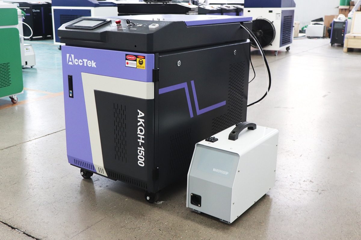
How To Maintain Laser Welding Machines?
Laser welding machines have become essential tools in modern manufacturing because they provide high welding speeds, precise heat control, narrow weld seams, low distortion, and excellent repeatability. They are widely used in automotive production, sheet metal fabrication, electronics, aerospace, kitchenware, medical equipment, battery manufacturing, and many other industries. However, even high-quality laser welding systems cannot maintain stable performance indefinitely without proper inspection, cleaning, adjustment, and preventive maintenance.
Laser welding machines are a complex system consisting of laser sources, welding head, optical components, cooling system, motion-control equipment, electrical components, shielding-gas system, wire-feeding unit, and safety devices. The condition of each component can directly affect beam quality, weld penetration, process stability, production efficiency, and operator safety. Contaminated protective lenses, insufficient cooling, unstable gas flow, loose electrical connections, damaged cables, or incorrect optical alignment may cause poor weld quality, unexpected alarms, reduced laser power, or costly equipment failure.
Regular maintenance helps prevent these problems before they interrupt production. It can extend the service life of the laser source and optical system, reduce unplanned downtime, lower repair expenses, improve energy efficiency, and ensure consistent welding results. Proper maintenance is also important for protecting operators from hazards associated with high-power laser radiation, electrical systems, compressed gases, moving parts, and welding fumes.
Maintenance requirements vary according to the machine type, operating environment, production intensity, laser power, cooling method, and materials being welded. Handheld laser welding machines used occasionally may require a different maintenance schedule from an automated system operating continuously in a high-volume production line.
This article explains how to maintain laser welding machines systematically. It covers daily, weekly, monthly, and long-term maintenance, including the laser source, welding head, protective optics, chiller, gas system, wire feeder, motion components, electrical cabinet, fume-extraction equipment, software, and safety devices. It also discusses common maintenance mistakes, warning signs, troubleshooting practices, and methods for creating an effective preventive maintenance program.
Table of Contents
Understanding Laser Welding Machine Maintenance
Laser welding machine maintenance refers to the systematic inspection, cleaning, adjustment, testing, servicing, and replacement of components required to keep the equipment operating safely and reliably. Unlike simple welding tools, laser welding machines combine optical, electrical, mechanical, cooling, gas-delivery, control, and safety systems. A problem in any one of these areas can affect welding quality, production efficiency, equipment life, or operator safety.
Effective maintenance is not limited to repairing the machine after a failure occurs. It begins with daily observation and preventive care. Operators should monitor changes in laser power, weld appearance, cooling temperature, shielding-gas flow, wire-feeding stability, machine noise, alarm frequency, and system response. Small abnormalities often provide early warnings of developing problems.
Maintenance procedures should follow the equipment manufacturer’s instructions because system designs differ between brands and models. The maintenance needs of handheld fiber laser welding machines may not be identical to those of an automated robotic laser welding cell. Laser power, duty cycle, workshop cleanliness, cooling method, welding material, and production volume can also influence the required maintenance schedule.
A structured maintenance program helps ensure that inspections are completed on time, worn parts are replaced before failure, and maintenance records are available for troubleshooting. By understanding what maintenance includes, why it is necessary, and how operating conditions affect service intervals, manufacturers can protect their equipment investment and maintain consistent welding performance.
What Laser Welding Machine Maintenance Includes
Laser welding machine maintenance includes all activities performed to preserve the machine’s original performance, prevent unexpected failures, and restore normal operation when abnormalities occur. These activities range from simple daily cleaning to specialized servicing by trained technicians.
One of the most important maintenance tasks is inspecting and cleaning the optical system. Protective lenses, focusing lenses, collimating components, and other optical surfaces must remain clean and undamaged. Welding smoke, metal vapor, dust, spatter, oil mist, and fingerprints can contaminate optical components. Contamination reduces laser transmission, increases heat absorption, and may cause the protective lens or internal optics to overheat. Operators should inspect protective lenses regularly and replace them when they become burned, cracked, cloudy, scratched, or difficult to clean.
The laser welding head also requires routine inspection. Operators should check the nozzle, copper tip, protective cover, focusing assembly, cable connections, and internal sealing condition. The nozzle should remain clean, centered, and free from deformation. A damaged or incorrectly installed nozzle can disturb shielding-gas flow and affect weld protection. The welding head should also be checked for signs of overheating, abnormal vibration, loose fasteners, or collision damage.
Cooling-system maintenance is another essential part of machine care. Water-cooled laser welding machines depend on the chiller to control the temperature of the laser source and welding head. Maintenance may include checking the coolant level, monitoring inlet and outlet temperatures, cleaning filters, inspecting hoses, removing dust from the condenser, and replacing the coolant at recommended intervals. The correct type of purified or deionized water should be used when specified by the manufacturer. Contaminated or unsuitable coolant can cause corrosion, scaling, biological growth, or blockage within the cooling circuit.
Air-cooled laser welding machines also need cooling-system maintenance. Operators should keep ventilation openings unobstructed, clean air filters, remove dust from fans and heat sinks, and ensure that the machine has sufficient space for airflow. An air-cooled system may require less coolant-related servicing, but it can be more sensitive to dust accumulation and high ambient temperatures.
Maintenance also covers the shielding-gas system. Gas hoses, pressure regulators, flowmeters, valves, fittings, and connectors should be checked for leaks, blockage, damage, or incorrect adjustment. Insufficient shielding gas can lead to oxidation, discoloration, porosity, unstable welds, and contamination of the welding optics. Excessive gas flow may create turbulence and reduce protection rather than improving it.
Machines equipped with wire feeders require additional inspection. Operators should clean the feeding mechanism, check drive rolls, inspect wire guides, confirm roller pressure, and examine the feeding tube for wear or blockage. The selected drive rolls and guide components should match the wire diameter. Incorrect adjustment can cause slipping, deformation, inconsistent feeding, or wire jams.
Electrical maintenance includes checking power cables, grounding connections, plugs, sockets, control wiring, emergency-stop circuits, and electrical cabinet components. Cooling fans and ventilation filters inside the electrical cabinet should be kept clean. Loose terminals, damaged insulation, moisture, excessive dust, or overheating can lead to alarms, unstable operation, electric shock risks, or component failure. Electrical inspections beyond basic visual checks should be completed by qualified personnel.
For automated systems, maintenance may also include guide rails, ball screws, racks, pinions, bearings, motors, robot joints, positioners, fixtures, and sensors. These components may require cleaning, lubrication, calibration, alignment, and fastener inspection. Accumulated debris or insufficient lubrication can reduce positioning accuracy and accelerate mechanical wear.
Software and control-system maintenance should not be overlooked. Important welding parameters, process programs, calibration data, and system settings should be backed up. Operators should review alarm histories, check communication connections, and install approved software or firmware updates when necessary. Unauthorized modifications may create compatibility problems or make troubleshooting more difficult.
Safety-system maintenance is equally important. Laser enclosures, protective windows, warning lights, door interlocks, emergency stops, fume-extraction systems, and personal protective equipment should be inspected regularly. Maintenance activities must never bypass laser-safety controls or expose untrained personnel to laser radiation.
Why Regular Maintenance Is Necessary
Regular maintenance is necessary because laser welding performance depends on the stable operation of many interconnected systems. A minor problem may gradually affect other components and eventually cause a major failure.
Consistent weld quality is one of the main reasons for maintaining the machine. Contaminated optics, unstable laser output, incorrect focus position, poor gas flow, or inconsistent wire feeding can change weld penetration, seam width, surface appearance, and mechanical strength. The machine may continue operating, but the resulting welds may no longer meet production requirements. Regular inspections help identify these changes before large quantities of defective parts are produced.
Maintenance also protects the optical system. Protective lenses are designed to shield more expensive internal components from smoke and spatter. If a damaged protective lens is not replaced promptly, contamination and heat may reach the focusing or collimating optics. Repairing or replacing these internal components is usually more expensive and time-consuming than replacing a protective window during routine maintenance.
Stable cooling is essential for the laser source and welding head. Excessive temperature can reduce laser efficiency, trigger alarms, shorten electronic-component life, and damage sensitive optical parts. Dirty filters, insufficient coolant, blocked hoses, failed fans, or a dusty condenser can reduce cooling performance. Regular maintenance keeps the cooling system within its designed operating range.
Planned maintenance also reduces unplanned downtime. An unexpected failure can stop production, delay delivery schedules, increase labor costs, and require emergency repair services. When wear components are inspected and replaced according to a schedule, servicing can be arranged during planned shutdowns rather than during critical production periods.
Regular maintenance extends equipment life. Dust, heat, moisture, vibration, contamination, and mechanical wear gradually affect machine components. Cleaning ventilation systems, tightening electrical connections, lubricating moving parts, and maintaining proper cooling conditions can slow this deterioration. Although maintenance cannot eliminate normal aging, it can prevent avoidable damage and help the machine operate effectively for a longer period.
Operator safety is another major consideration. Laser welding systems involve high-intensity laser radiation, high-voltage electrical components, compressed gas, hot metal, welding fumes, and moving equipment. Damaged cables, failed interlocks, blocked extraction filters, leaking gas connections, or defective emergency stops can create serious hazards. Routine safety inspections help ensure that protective devices remain functional.
Maintenance records can also improve troubleshooting. When inspections, component replacements, alarms, parameter changes, and repair activities are documented, technicians can identify recurring problems and determine whether failures are related to operating conditions, consumable quality, incorrect settings, or component wear.
Finally, regular maintenance helps control operating costs. Replacing inexpensive consumables at the correct time can prevent damage to costly components. Clean cooling and ventilation systems may also improve energy efficiency. More importantly, stable equipment produces fewer defective welds and requires less rework, inspection, and material replacement.
Preventive Maintenance and Corrective Maintenance
Laser welding machine maintenance can generally be divided into preventive maintenance and corrective maintenance. Both are necessary, but they serve different purposes.
Preventive maintenance is performed before a serious failure occurs. It includes scheduled cleaning, inspection, testing, adjustment, lubrication, calibration, and consumable replacement. Daily checks of the protective lens, nozzle, cooling system, gas pressure, and safety devices are examples of preventive maintenance. Weekly or monthly cleaning of filters, fans, wire feeders, and electrical cabinets also belongs to this category.
The purpose of preventive maintenance is to detect deterioration early and keep components within acceptable operating conditions. It is based on the principle that many failures develop gradually. A cooling filter becomes increasingly blocked, a protective lens becomes progressively contaminated, or a cable connection slowly loosens. Detecting these conditions early is usually less expensive than repairing the resulting damage.
Preventive maintenance may be time-based, usage-based, or condition-based. Time-based maintenance is performed at fixed intervals, such as daily, weekly, monthly, or annually. Usage-based maintenance depends on operating hours, welding cycles, or production volume. Condition-based maintenance relies on inspection findings, temperature trends, alarm data, lens condition, coolant quality, or other indicators of actual equipment health.
Corrective maintenance is performed after a fault, failure, or unacceptable performance condition has been identified. Examples include replacing a damaged welding head, repairing a failed chiller pump, correcting a wire-feeding problem, replacing a faulty sensor, or troubleshooting unstable laser output.
Corrective maintenance may be planned when a developing problem is discovered during inspection but does not require an immediate shutdown. It may also be unplanned when a component fails suddenly. Emergency corrective maintenance is usually more disruptive because production has already stopped and replacement parts may not be immediately available.
Corrective maintenance should address the root cause rather than only the visible symptom. For example, repeatedly replacing burned protective lenses without checking gas flow, nozzle alignment, lens installation, sealing condition, or welding spatter will not solve the underlying problem. Similarly, resetting an overheating alarm without inspecting the chiller, coolant flow, filters, and ambient temperature may allow the fault to return.
A balanced maintenance strategy uses preventive maintenance to reduce the frequency of failures while retaining clear corrective procedures for problems that cannot be prevented. Preventive maintenance does not guarantee that every failure will be avoided, but it substantially improves reliability and makes machine behavior more predictable.
Maintenance Frequency Depends on Operating Conditions
Maintenance frequency should not be based only on a generic calendar. The actual operating environment and workload can significantly change how quickly components become contaminated, worn, or damaged.
Machines operating for several shifts per day generally require more frequent inspection than machines used occasionally. Continuous production increases the operating hours of the laser source, cooling system, fans, pumps, wire feeder, and motion components. High-duty-cycle applications may require daily lens inspections and shorter filter, coolant, and consumable replacement intervals.
The materials being welded also affect maintenance needs. Some metals, coatings, surface treatments, oils, or contaminants produce more smoke, vapor, or spatter than others. Welding reflective materials or workpieces with inconsistent surface conditions may also expose protective optics to greater risk. Applications that generate heavy fumes require more frequent inspection of the welding head and extraction system.
Workshop cleanliness is another major factor. Machines used in dusty fabrication shops may accumulate particles inside ventilation filters, electrical cabinets, fans, and cooling components. Nearby grinding, cutting, polishing, or painting operations can increase airborne contamination. In these environments, components may need to be cleaned much more frequently than the manufacturer’s standard schedule suggests.
Temperature and humidity influence maintenance intervals as well. High ambient temperatures increase the load on the chiller or air-cooling system. Low temperatures may create condensation or freezing risks if unsuitable coolant is used. High humidity can contribute to corrosion, moisture accumulation, electrical leakage, and optical contamination. Machines should operate within the environmental limits specified by the manufacturer.
The complexity of the welding process also matters. Automated systems with robots, positioners, sensors, fixtures, and multiple motion axes have more components that require inspection and calibration. Handheld systems may have fewer moving parts, but the welding gun, fiber cable, protective lens, nozzle, and wire feeder may experience more physical handling and accidental impact.
Operator practices can either reduce or increase maintenance requirements. Careful handling, proper startup and shutdown procedures, correct parameter selection, clean workpieces, and timely lens replacement help protect the machine. Poor cable handling, operation with insufficient gas, repeated collisions, or ignoring alarms can shorten service intervals and cause premature damage.
The age and condition of the machine should also be considered. Older equipment may require more frequent inspection because seals, fans, pumps, cables, and electrical components gradually deteriorate. A machine with a history of repeated faults may need additional condition monitoring until the underlying cause has been resolved.
Manufacturers should begin with the maintenance intervals recommended in the equipment manual and adjust them using actual operating data. If filters remain clean and temperatures are stable, some tasks may not need to be performed more frequently. If lenses repeatedly become contaminated or cooling performance declines rapidly, the inspection interval should be shortened. Maintenance schedules should therefore be treated as living documents that are updated according to machine condition, production requirements, and recorded maintenance history.
Understanding laser welding machine maintenance requires recognizing that the equipment is an integrated system rather than a single welding tool. Maintenance includes the laser source, welding head, optics, cooling system, gas-delivery components, wire feeder, electrical system, control software, mechanical motion system, extraction equipment, and safety devices. Each part contributes to stable laser output, accurate processing, consistent weld quality, and safe operation.
Regular maintenance is necessary to reduce contamination, overheating, mechanical wear, electrical faults, poor shielding, inconsistent wire feeding, and unexpected shutdowns. It protects expensive optical and electronic components while helping manufacturers reduce defective welds, repair costs, and production interruptions. It also provides an opportunity to verify that emergency stops, interlocks, warning devices, and other safety systems remain functional.
Preventive and corrective maintenance should work together. Preventive maintenance identifies deterioration before failure, while corrective maintenance restores operation after a problem occurs. The most effective maintenance strategy emphasizes prevention but also includes clear troubleshooting and repair procedures.
Maintenance frequency should be adjusted according to operating hours, production intensity, material characteristics, workshop cleanliness, ambient conditions, machine design, operator practices, and equipment age. By combining manufacturer recommendations with actual machine data and documented inspection results, users can establish a practical maintenance program that supports reliable performance and long-term equipment value.
Follow Safety Procedures Before Performing Maintenance
Laser welding machine maintenance must begin with safety preparation. Laser welding machines combine high-intensity laser radiation, high-voltage electrical components, stored electrical energy, pressurized gases, hot surfaces, moving mechanisms, cooling circuits, and potentially hazardous welding residues. Even a routine task such as cleaning a nozzle, replacing a protective lens, checking a cable, or servicing a wire feeder can become dangerous if the machine is not shut down and isolated correctly.
Maintenance personnel should never assume that pressing the stop button makes the equipment completely safe. Electrical power may still be present in the laser source, control cabinet, chiller, robotic system, or auxiliary equipment. Capacitors may retain stored energy after shutdown, pneumatic lines may remain pressurized, and automated components may move if they receive an unexpected command. Some systems can also emit laser energy during testing, calibration, fault recovery, or accidental activation.
Before beginning work, operators should identify all energy sources connected to the machine. These may include the main electrical supply, separate power supplies for the laser source and chiller, compressed air, shielding gas, pneumatic actuators, automated loading systems, robots, positioners, and stored mechanical energy. The maintenance area should be controlled so that unauthorized personnel cannot enter or restart the equipment.
Safety procedures must follow the machine manufacturer’s instructions, the facility’s internal safety rules, and applicable laser, electrical, and occupational-safety requirements. Maintenance that involves internal electrical circuits, laser-source modules, optical alignment, sealed assemblies, or safety-control systems should be performed only by trained and authorized technicians. Proper preparation protects personnel, prevents equipment damage, and reduces the risk of accidentally creating unsafe operating conditions after maintenance.
Shut Down the Machine Correctly
Laser welding machines should be shut down using the manufacturer’s specified sequence before any maintenance work begins. An incorrect shutdown can leave systems energized, interrupt cooling too early, damage sensitive components, or allow the machine to restart unexpectedly.
The operator should first stop the welding process and move the welding head, robot, or motion system to a safe position. The workpiece should be allowed to cool, and hot metal, molten residue, sharp edges, and recently welded fixtures should be identified. Wire feeding, gas flow, automatic motion, and other active processes should be stopped before the control software is closed.
The laser output should then be disabled through the normal control interface. Depending on the machine design, this may involve releasing the welding trigger, selecting standby mode, disabling laser enable, stopping the process program, and turning the key switch to the off position. Emergency-stop buttons should not normally be used as a substitute for the standard shutdown procedure unless an emergency exists. Emergency stops are designed to stop hazardous motion or emission quickly, but they may not perform the controlled shutdown required for sensitive equipment.
The laser source should be turned off according to the recommended sequence. Some laser sources require a brief cooling period after welding has stopped. The chiller or cooling system may need to continue operating temporarily so that residual heat can be removed from the laser source and welding head. Turning off cooling immediately after heavy operation can trap heat inside critical components and contribute to thermal stress.
After the required cooling period, auxiliary systems can be shut down. These may include the chiller, fume extractor, wire feeder, compressed-air supply, shielding-gas supply, robot, positioner, and loading equipment. Gas cylinder or central gas valves should be closed when the maintenance task involves gas hoses, regulators, nozzles, or fittings. Pressure remaining in the system should be released safely when required.
The main power supply should then be disconnected. The operator should confirm that control screens, indicators, fans, pumps, and motion systems have stopped. However, the absence of lights or sound does not prove that the machine is electrically safe. Certain circuits may remain energized or retain stored charge.
The maintenance manual should specify the necessary waiting period before opening electrical cabinets or accessing internal components. Capacitors inside laser sources, power supplies, servo drives, and frequency converters can retain hazardous voltage after power has been removed. Personnel must respect the stated discharge time and verify the absence of voltage with approved testing equipment when electrical access is required.
Before work begins, the machine should be inspected for residual hazards. The welding head may remain hot, cooling lines may contain pressure, mechanical axes may be able to fall or move, and pneumatic actuators may remain extended. These hazards must be controlled before components are loosened or removed.
A standardized shutdown checklist helps prevent skipped steps. The checklist should match the specific machine configuration rather than relying on a generic sequence. Handheld laser welding machines, robotic welding cells, and multi-axis automated systems may each require different shutdown procedures.
Use Lockout and Tagout Procedures
Lockout and tagout procedures are used to prevent equipment from being energized, started, pressurized, or moved while maintenance is being performed. They are especially important when personnel must enter a guarded area, open an electrical cabinet, remove protective covers, disconnect gas lines, service moving components, or work near the laser emission path.
Lockout involves physically securing an energy-isolating device in the safe or off position. This may include locking the main electrical disconnect, closing and locking a compressed-air valve, isolating gas supplies, disconnecting auxiliary equipment, or securing a mechanical component against movement. Tagout involves attaching a clearly visible warning label that identifies the person performing the maintenance, the reason for isolation, and the date or status of the work.
Simply turning off the control panel or pressing a software stop button is not equivalent to energy isolation. Control buttons can fail, software can restart, and another person can activate the machine. The main energy source must be physically isolated wherever the maintenance task exposes personnel to hazardous energy.
Before applying locks, maintenance personnel should notify affected operators and supervisors that the machine will be unavailable. The system should then be shut down normally, and all identified energy sources should be isolated. Each authorized worker should apply a personal lock when required by the facility’s procedure. A lock should not be removed by another person except under a formally controlled exception process.
Stored energy must also be addressed. Electrical capacitors should be allowed to discharge. Pneumatic pressure should be released. Suspended axes, lifting mechanisms, robotic arms, doors, or fixtures should be lowered, blocked, pinned, or otherwise secured. Springs, counterweights, gravity-loaded components, and rotating parts may continue to present hazards after the main power is disconnected.
After isolation, personnel should verify that the lockout is effective. The machine’s start controls may be tested after confirming that no one is exposed to danger. The system should not power up, move, feed wire, activate gas, or enable the laser. The controls should then be returned to the off position before maintenance begins.
Automated laser welding cells may have multiple energy sources and separate disconnects. The robot, laser source, chiller, wire feeder, extraction system, positioner, conveyor, and loading equipment may each have independent power or pneumatic supplies. Locking only the main welder may not isolate the entire system.
When maintenance is completed, all tools, cleaning materials, replacement parts, and temporary barriers should be removed. Guards, covers, interlocks, and access panels must be restored. Personnel should confirm that everyone is clear of the hazardous area before locks are removed. Energy should be restored in a controlled sequence, and the machine should be tested under supervised conditions.
Lockout and tagout procedures should be documented and machine-specific. Employees must be trained to understand which energy sources require isolation and how verification should be performed. A well-designed procedure protects both the technician working on the equipment and other personnel who might otherwise attempt to restart it.
Prevent Accidental Laser Emission
Preventing accidental laser emission is one of the most important requirements during maintenance. The beam produced by laser welding machines can cause severe eye injuries, skin burns, fires, and damage to surrounding equipment. High-power laser radiation may be hazardous even when it is reflected from metal surfaces or passes through damaged protective components.
The laser source must be placed in a disabled state before maintenance begins. This may involve switching off laser enable, removing the control key, isolating the laser-source power supply, disconnecting the welding trigger, or activating an approved service mode. The exact procedure depends on the equipment design and should be taken from the manufacturer’s documentation.
The welding gun or processing head should never be treated as safe merely because the trigger is not being pressed. A damaged trigger, software fault, remote command, incorrectly wired control circuit, or unexpected restart could activate the beam. The trigger should be protected against accidental operation, and the welding head should be positioned so that it cannot point toward personnel, doors, windows, reflective objects, or combustible materials.
When handheld laser welding machines are being serviced, the gun should be placed in its designated holder or on a stable, nonreflective surface. It should not be carried by the optical fiber, trigger cable, or gas hose. The optical cable should be arranged without sharp bends, twisting, crushing, or tension. Damage to the cable can create serious laser-leakage risks.
Keys, access codes, and remote controls used to enable laser output should remain under the control of authorized personnel. Removing the key switch or disabling the control permission reduces the chance that another person will activate the machine while maintenance is in progress.
Safety interlocks must never be bypassed simply to make maintenance faster. Door interlocks, enclosure sensors, workpiece-contact circuits, protective-cover switches, emergency stops, and beam-emission indicators are designed to prevent hazardous exposure. Defeating one safety function can allow the machine to emit laser energy in an uncontrolled condition.
Some diagnostic or calibration procedures require controlled laser emission. These tasks should be performed only by trained laser-service personnel using an approved service procedure. The area should be restricted, warning signs and indicators should be active, and unnecessary personnel should be removed. Suitable beam stops, barriers, protective enclosures, and viewing systems should be used to contain the beam.
Low-power pilot beams should also be treated carefully. A visible aiming beam may indicate the laser path, but it does not guarantee that the high-power welding beam is disabled. Personnel should verify the actual laser-enable status through the machine’s approved indicators and isolation procedure.
Reflective jewelry, watches, tools, polished metal objects, mirrors, and glass components should be removed from the beam area. Reflections from copper, aluminum, stainless steel, and other workpieces can travel in unexpected directions. Maintenance work near the welding head should therefore be performed only after emission has been positively prevented.
After servicing, the beam path, welding head, nozzle, protective lens, covers, and interlocks should be checked before laser output is restored. Any removed protective components must be reinstalled correctly. Laser operation should resume only after the maintenance area has been cleared and the system has passed the required safety checks.
Wear Suitable Personal Protective Equipment
Personal protective equipment provides an additional layer of protection during laser welding machine maintenance. It does not replace proper shutdown, isolation, guarding, ventilation, or safe work procedures, but it helps reduce exposure to hazards that cannot be eliminated.
Suitable laser-protective eyewear may be required whenever there is a possibility of laser emission or exposure to reflected radiation. The eyewear must be selected for the specific laser wavelength and optical density specified for the equipment. Generic welding goggles, dark glasses, or ordinary safety glasses do not necessarily protect against fiber-laser radiation.
Laser safety glasses should be inspected before use. Cracked lenses, damaged coatings, loose frames, heavy scratches, or contaminated surfaces may reduce protection. Eyewear should be stored in a protective case and cleaned according to the supplier’s instructions. Personnel must understand that approved laser eyewear does not make it safe to look directly into a beam or reflected beam.
Safety glasses with side protection are generally appropriate for cleaning, component replacement, and mechanical maintenance where particles, dust, cleaning fluid, wire fragments, or metal debris may be released. Face shields may be needed when handling pressurized coolant, compressed air, chemicals, or contaminated filters. The required protection should be selected according to the actual task.
Protective gloves should be chosen carefully. Heat-resistant gloves may be necessary when handling recently welded workpieces, nozzles, fixtures, or hot components. Cut-resistant gloves can protect against sharp sheet-metal edges and wire ends. Chemical-resistant gloves may be required when replacing coolant, cleaning parts, or handling approved cleaning agents.
Gloves should not be worn near rotating or moving machinery if they create an entanglement hazard. Mechanical components must be isolated before they are touched. Loose gloves, clothing, hair, jewelry, and lanyards can become caught in wire feeders, fans, motors, guide rails, or automated motion equipment.
Maintenance personnel should wear suitable work clothing that covers exposed skin and is resistant to sparks or hot particles where necessary. Synthetic fabrics that melt easily may not be appropriate for certain welding-related tasks. Safety footwear should protect against dropped components, sharp objects, slippery coolant, and electrical or static hazards where applicable.
Respiratory protection may be required when servicing fume-extraction systems, replacing contaminated filters, cleaning welding residue, or working in areas with hazardous dust. Filters may contain fine metal particles and process contaminants. They should be handled carefully to avoid releasing collected material back into the workshop.
Hearing protection may be necessary when compressed air, extraction equipment, pumps, or other machinery creates high noise levels. However, compressed air should not be used to blow dust from optical components, clothing, or electrical cabinets unless the manufacturer specifically permits it. Blowing dust can spread contamination and drive particles deeper into sensitive assemblies.
Electrical work may require insulated gloves, electrical-rated tools, arc-flash protection, and other specialized equipment. Such work should be performed only by qualified personnel under the facility’s electrical-safety program. Standard maintenance gloves are not a substitute for properly rated electrical protection.
Personal protective equipment should remain clean, correctly fitted, readily available, and suitable for the task. Facilities should define PPE requirements in their maintenance procedures and provide training on selection, inspection, use, storage, and replacement.
Do Not Open Sealed Optical or Laser Modules
Sealed optical and laser modules should not be opened by ordinary operators or general maintenance personnel. These assemblies are designed, aligned, calibrated, cleaned, and sealed under controlled manufacturing or service conditions. Opening them without the correct equipment and training can create safety risks and permanently damage the machine.
Fiber laser sources contain sensitive optical fibers, pump diodes, combiners, isolators, control electronics, power supplies, and thermal-management components. Internal parts may carry hazardous voltage or retain stored electrical energy after shutdown. The laser source may also contain invisible high-power radiation paths that are not safe to access outside specialized service conditions.
The welding head may include collimating lenses, focusing optics, scanning mirrors, sensors, internal seals, and precision alignment components. Some externally accessible consumables, such as protective lenses, nozzles, or cover windows, may be replaced by trained operators according to the manufacturer’s procedure. Internal optical groups should not be disassembled unless the manufacturer specifically authorizes field servicing.
Opening a sealed optical module can introduce dust, oil, moisture, fingerprints, fibers, or cleaning residue. Even extremely small contaminants can absorb laser energy and create localized heating. This can burn optical coatings, crack lenses, reduce transmission, distort the beam, and damage other components.
Incorrect reassembly may also change optical alignment. A lens installed backward, a seal placed incorrectly, a loose retaining ring, or an improperly tightened component can cause unstable focus, overheating, air leakage, contamination, or internal reflection. These problems may not be immediately visible but can lead to rapid failure when high-power laser energy is applied.
Sealed modules may contain tamper labels, security screws, calibration seals, or warranty markings. Unauthorized opening can void the equipment warranty or transfer liability to the user. It may also make it more difficult for the manufacturer to diagnose the original problem.
If internal contamination, power loss, unusual beam behavior, repeated lens damage, abnormal noise, overheating, or internal optical failure is suspected, the machine should be stopped, and the authorized service provider contacted. Maintenance personnel should record alarm messages, operating conditions, photographs of accessible components, laser-power behavior, and recent maintenance history. This information can help the service technician identify the problem without unnecessary disassembly.
Operators should also avoid opening sealed fiber connections or disconnecting optical fibers unless the procedure is specifically approved. Fiber connectors are highly sensitive to contamination and damage. A contaminated connector can burn immediately when laser power is applied and may damage both the fiber cable and laser source.
Only approved consumable areas should be opened during routine maintenance. The operator manual should clearly identify which protective windows, filters, covers, nozzles, or external components are user-serviceable. Any component not identified as serviceable should be treated as a sealed assembly.
Respecting sealed modules is not merely a warranty concern. It protects personnel from invisible laser radiation and hazardous electrical energy while preserving the cleanliness, alignment, and calibration required for stable welding performance.
Safety preparation must come before every laser welding machine maintenance task, regardless of how simple the task appears. The machine should be stopped using the correct shutdown sequence, allowed to cool when necessary, and disconnected from all relevant energy sources. Electrical power, gas pressure, pneumatic energy, mechanical motion, stored charge, and residual heat must all be considered.
Lockout and tagout procedures provide physical protection against unexpected startup or energy release. They are particularly important when guards are removed, electrical cabinets are opened, automated cells are entered, or components connected to compressed gas and motion systems are serviced. Isolation should always be verified before maintenance begins.
Accidental laser emission must be prevented by disabling the laser source, controlling enable keys, securing the welding gun, protecting the trigger, and keeping interlocks active. Maintenance that requires controlled laser output should be restricted to trained personnel working under an approved procedure.
Suitable personal protective equipment should be selected according to the hazards of the specific task. Laser-rated eyewear, safety glasses, gloves, protective clothing, safety footwear, respiratory protection, and electrical PPE may all be required in different situations. PPE should support, rather than replace, effective engineering controls and safe work practices.
Finally, sealed laser sources, internal optical assemblies, and unauthorized fiber connections should not be opened. These components contain sensitive, precisely aligned, and potentially hazardous systems that require specialized service conditions. Following these precautions helps protect maintenance personnel, preserve equipment performance, and prevent costly damage caused by unsafe or unauthorized servicing.
Establish a Practical Maintenance Schedule
A practical maintenance schedule turns general equipment-care recommendations into specific, repeatable tasks. Without a clear schedule, maintenance is often delayed until weld quality declines, alarms appear, or the machine stops unexpectedly. A structured plan helps operators identify small problems early, replace consumable parts at the correct time, protect expensive components, and reduce unplanned production interruptions.
Laser welding machine maintenance should be organized according to task frequency. Daily tasks usually focus on visual inspection, cleaning, operating-condition checks, and immediate safety concerns. Weekly and monthly tasks involve more detailed cleaning, testing, adjustment, and examination of supporting systems. Quarterly, semiannual, and annual maintenance may require deeper inspection, calibration, coolant replacement, electrical testing, and service by qualified technicians.
The schedule should be based on the machine manufacturer’s instructions but also reflect actual operating conditions. A machine used continuously in a dusty fabrication workshop may require much more frequent cleaning than a machine used occasionally in a clean production area. Welding materials, laser power, duty cycle, fume generation, cooling method, automation level, and operator practices can all affect maintenance intervals.
Maintenance responsibilities should be clearly assigned. Operators may perform routine visual checks and approved consumable replacement, while trained maintenance personnel handle mechanical, electrical, cooling, and calibration work. Internal laser-source servicing, optical alignment, and specialized repairs should normally be reserved for authorized service technicians.
Every completed task should be recorded. Maintenance records should include the date, machine operating hours, inspection findings, replaced parts, alarm history, corrective actions, and the name of the person performing the work. These records make it easier to identify recurring faults, predict component wear, and adjust maintenance intervals based on to machine’s actual condition.
Daily Maintenance Tasks
Daily maintenance should be completed before operation, during production when appropriate, and after the machine is shut down. These tasks are generally quick, but they have a major effect on equipment reliability and weld consistency.
Before starting the machine, the operator should inspect the overall condition of the equipment. External covers, access doors, protective enclosures, warning labels, and safety barriers should be intact. The work area should be clean, dry, and free from unnecessary reflective objects, combustible materials, loose tools, or obstructions.
The welding head or handheld welding gun should be examined carefully. The operator should check for loose parts, impact marks, overheating, contamination, damaged seals, or abnormal wear. The nozzle should be clean, correctly installed, and free from deformation. Spatter or residue around the nozzle can disturb shielding-gas flow and affect weld appearance.
The protective lens should be inspected according to the manufacturer’s approved procedure. It should be free from burns, cracks, dark spots, cloudiness, heavy dust, and visible contamination. A damaged lens should be replaced promptly rather than cleaned repeatedly and returned to service. Continuing to operate with a burned protective lens can allow heat and contamination to reach more expensive internal optics.
The optical-fiber cable, control cable, gas hose, cooling hose, and wire-feeding cable should be checked for crushing, twisting, sharp bending, abrasion, cuts, loose connectors, or signs of overheating. Handheld welding guns should never be dragged by their cables or allowed to hang from the fiber. The minimum bending radius specified by the manufacturer must always be respected.
The cooling system should be checked before laser output is enabled. For water-cooled machines, the operator should confirm the coolant level, temperature, pressure, and flow status. Hoses should be inspected for leaks, kinks, bubbles, or loose fittings. Any low-flow, overtemperature, or chiller alarm should be investigated before welding begins.
Air-cooled machines require inspection of ventilation openings, cooling fans, and intake filters. Airflow should not be blocked by walls, stored materials, dust buildup, or machine covers. An unusual fan noise or rapidly increasing machine temperature may indicate a developing cooling problem.
The shielding-gas supply should also be inspected. The gas cylinder or central supply should contain sufficient gas, and the regulator, flowmeter, hoses, fittings, and connectors should show no signs of leakage or damage. Gas flow should be set according to the welding procedure rather than estimated visually.
If the machine uses compressed air, the air supply should be dry, clean, stable, and within the specified pressure range. Water, oil, or particles in compressed air can contaminate the welding process and damage pneumatic components.
Machines equipped with wire feeders should be checked for smooth wire movement. The wire spool should be installed securely, the wire should feed in the correct direction, and the drive-roll pressure should be appropriate. The feeding tube should not be sharply bent, and the wire tip should be clean and correctly positioned relative to the welding head.
The operator should inspect the workpiece-contact or safety-clamp connection when the machine uses this type of protection. The clamp should make reliable electrical contact with clean metal. Paint, rust, scale, or loose attachment can prevent the safety circuit from functioning correctly.
Emergency stops, door interlocks, warning lights, protective shutters, and other operator-checkable safety devices should be tested according to the approved startup procedure. A failed interlock or warning indicator should never be bypassed to continue production.
During operation, the operator should observe laser power stability, weld appearance, penetration, seam width, color, spatter, noise, wire feeding, gas flow, and machine temperature. Changes in these conditions may indicate lens contamination, incorrect focus, unstable gas delivery, cooling problems, or mechanical damage.
Alarm messages should not simply be reset without investigation. The operator should record the alarm code, operating conditions, affected program, and any visible symptoms. Repeated alarms often provide early evidence of a developing fault.
After production, the machine and surrounding work area should be cleaned. Loose metal fragments, wire pieces, dust, and welding residue should be removed using approved methods. The welding head, nozzle, gun holder, fixture surfaces, and wire-feeding area should be kept free from accumulated debris.
The machine should then be shut down in the correct sequence. Gas valves should be closed when required, and the welding head should be returned to its designated storage position. The fiber cable and hoses should be arranged without tension or sharp bends. Any defect discovered during the day should be entered in the maintenance log and reported before the next shift begins.
Weekly Maintenance Tasks
Weekly maintenance provides an opportunity to inspect areas that may not require attention every day but can gradually accumulate contamination or wear. The exact interval may need to be shortened in high-volume or dusty environments.
The protective lens and its holder should receive a more detailed inspection. Maintenance personnel should check the lens seal, retaining components, O-rings, and seating surfaces. Dust or residue around the lens holder can enter the optical cavity when the lens is replaced. Replacement should therefore be carried out in a clean area using lint-free materials and approved tools.
The welding nozzle should be removed and inspected for internal blockage, deformation, burned surfaces, or spatter buildup. The gas passage should remain unobstructed. A damaged nozzle should be replaced because even a small deformation can change gas direction and affect shielding performance.
The welding-head exterior should be cleaned carefully. Cooling ports, gas connections, sensor areas, and protective covers should remain free from dust and residue. Cleaning agents should never be sprayed directly into optical openings, electrical connectors, or ventilation passages.
The wire feeder should be opened and cleaned according to the manufacturer’s instructions. Metal particles and wire dust can accumulate around the drive rolls, guide tubes, and tension mechanism. The drive rolls should be inspected for wear, contamination, or incorrect groove size. Feeding pressure should be sufficient to move the wire without crushing or deforming it.
The wire liner, feeding tube, and contact components should be checked for resistance or blockage. If wire movement is irregular, the cause should be corrected before increasing drive-roll pressure. Excessive pressure can damage the wire and accelerate feeder wear.
The chiller intake screen, air filter, or condenser surface should be inspected and cleaned. Dust accumulation reduces heat-transfer efficiency and may cause the chiller to run continuously at higher load. Cleaning should be performed with the machine isolated and by methods approved for the specific chiller.
Coolant hoses, clamps, fittings, and connections should be examined closely for seepage, discoloration, hardening, swelling, or abrasion. Small leaks can gradually reduce coolant volume and introduce air into the system.
Electrical and signal cables should be checked for loose connectors, worn protective sleeves, damaged strain relief, or contact with hot and moving surfaces. Particular attention should be given to cables connected to handheld guns, robots, positioners, and moving axes.
The gas system should be leak-tested using an approved method. Regulators, flowmeters, quick connectors, valves, and hose joints should be inspected. Open flames should never be used to detect gas leaks.
Fume-extraction equipment should be checked for adequate suction. The collection hood, extraction arm, ducting, and intake openings should be positioned correctly and free from blockage. A noticeable reduction in airflow may indicate a loaded filter or contaminated duct.
For automated machines, guide surfaces, sensors, fixtures, positioners, and robot dress packs should be cleaned and inspected. Weld residue should not be allowed to cover sensors or accumulate around moving components. Loose fixture parts can affect positioning accuracy and create collision risks.
Safety signs, barriers, viewing windows, laser curtains, door seals, and enclosure panels should also be examined. Damaged or heavily contaminated protective windows may reduce visibility or compromise enclosure performance.
At the end of the weekly inspection, operators should review recent alarms, weld-quality complaints, consumable use, and abnormal events. A sudden increase in protective-lens replacement, for example, may indicate incorrect gas flow, excessive spatter, poor lens sealing, or unsuitable welding parameters.
Monthly Maintenance Tasks
Monthly maintenance should be more thorough than routine daily and weekly care. It may require a planned production stop so that components can be safely isolated, opened, cleaned, tested, and adjusted.
The cooling system should receive detailed attention. Coolant level, color, clarity, odor, conductivity, and contamination should be checked when applicable. Cloudy coolant, particles, biological growth, discoloration, or deposits may indicate that replacement or system cleaning is required.
Chiller filters should be inspected and cleaned or replaced according to their condition. The condenser, fan blades, ventilation passages, and heat-exchange surfaces should be cleaned. Chiller temperature settings should be compared with the manufacturer’s recommendations and actual workshop conditions.
Coolant inlet and outlet temperatures should be reviewed during machine operation. An increasing temperature difference or declining flow may indicate a blocked filter, weak pump, restricted hose, contaminated cooling channel, or insufficient coolant.
The welding head should be inspected for focus stability, sensor condition, mechanical looseness, and signs of internal contamination. User-serviceable protective components may be removed and examined, but sealed optical assemblies should not be opened.
Nozzle centering and alignment should be checked when the machine design permits. A misaligned nozzle can create uneven gas flow, interfere with the laser path, and produce asymmetric welds. Any alignment procedure should be completed using approved tools and methods.
The electrical cabinet should be inspected by qualified personnel. The machine must be safely isolated before the cabinet is opened. Dust should be removed using approved cleaning methods, and ventilation filters should be cleaned or replaced. Cooling fans should rotate freely and operate without unusual noise.
Electrical terminals, plugs, grounding conductors, relays, contactors, power supplies, and cable connections should be checked for looseness, discoloration, burning, corrosion, or overheating. Thermal inspection may be useful where permitted, especially for machines with high duty cycles.
The main power cable and grounding system should be inspected. Reliable grounding is essential for electrical safety, electromagnetic stability, and correct operation of some machine safety functions.
Mechanical components on automated systems should be examined for lubrication condition, backlash, unusual vibration, loose bolts, damaged covers, and abnormal wear. Guide rails, racks, gears, ball screws, bearings, robot joints, positioners, and slides should be maintained according to their individual lubrication requirements.
Excessive lubricant should be avoided because it can attract dust and contamination. The correct lubricant type and quantity should be used. Mixing incompatible lubricants can reduce protection and damage seals.
Fixtures, clamps, worktables, and positioning components should be checked for wear and accuracy. Repeated thermal cycles, impacts, and spatter buildup can change part positioning. Worn locating pins or loose clamps may create weld variation even when the laser welding system itself is operating correctly.
The wire-feeding system should be examined in greater detail. Drive rolls, tension mechanisms, liners, guide tubes, wire-straightening components, contact tips, and spool holders should be inspected for wear. Wire-feed speed should be verified against the programmed value if inconsistency has been observed.
Fume-extraction filters should be checked according to pressure-drop indicators, operating hours, or visible contamination. Prefilters may require cleaning or replacement more frequently than main filters. Used filters should be handled as contaminated process waste.
Software and process data should also be reviewed monthly. Important parameter libraries, machine settings, calibration values, robot programs, and production recipes should be backed up to an approved storage location. Unauthorized program changes should be identified and corrected.
Alarm histories should be examined for repeated temperature, flow, communication, interlock, positioning, or laser-source errors. Trend analysis can reveal problems before they cause a shutdown.
Safety devices should receive a documented functional test. Emergency stops, door interlocks, laser-emission indicators, safety relays, protective shutters, workpiece-detection circuits, and enclosure switches should all respond correctly. A safety device that behaves inconsistently should be repaired immediately.
Quarterly and Semiannual Maintenance
Quarterly and semiannual maintenance is intended to assess longer-term equipment condition. These inspections are usually more technical and may require trained maintenance personnel or support from the machine supplier.
The laser output should be evaluated for stability and consistency. Depending on the available equipment and manufacturer’s procedure, technicians may compare actual output performance with historical records or process results. A gradual decline may be related to optical contamination, cooling instability, source aging, calibration drift, or unsuitable operating conditions.
Welding-head focus accuracy and calibration should be checked. Automated focus systems, scanning mechanisms, oscillation settings, and position sensors may drift over time. Verification is especially important when the machine performs precision welding or frequently changes material thickness and joint type.
The optical path should be inspected only within the user-serviceable limits defined by the manufacturer. Accessible protective optics and external beam-delivery components may be checked, but internal sealed modules should remain closed. Evidence of repeated internal contamination or abnormal power loss should be referred to an authorized service provider.
The cooling circuit may require partial draining, flushing, or coolant replacement at quarterly or semiannual intervals, depending on the coolant type, operating hours, environment, and manufacturer’s instructions. Water quality should be maintained within specified conductivity, cleanliness, and temperature limits.
Pumps, fans, compressors, valves, temperature sensors, flow sensors, and pressure switches should be tested. A component can still operate while gradually losing performance, so technicians should look for abnormal noise, vibration, leakage, delayed response, or unstable readings.
The electrical system should receive a more detailed inspection. Power connections, control terminals, grounding points, protective devices, contactors, relays, servo drives, and power supplies should be checked. Loose electrical connections should be tightened only to the manufacturer’s specified torque.
Cabinet cooling performance should be evaluated under production conditions. High internal temperature shortens the life of power electronics and control components. Damaged fans, loaded filters, blocked ventilation, and excessive workshop temperature should be corrected.
For automated laser welding systems, motion accuracy should be tested. Robot repeatability, positioner accuracy, fixture alignment, axis backlash, home-position consistency, and sensor calibration should be reviewed. Small positioning errors can cause major quality problems when welding narrow seams or complex three-dimensional joints.
Robot cables, hoses, fiber-routing systems, cable tracks, and dress packs should be inspected throughout their full range of motion. Repeated bending can cause internal wire breakage or fiber damage before external wear becomes obvious.
Mechanical structures should be checked for loose fasteners, foundation movement, impact damage, distortion, and abnormal vibration. Bolted connections on robots, positioners, fixtures, and welding-head mounts may loosen over time.
The shielding-gas system should be checked for regulator accuracy, flow stability, contamination, hose aging, and valve performance. Filters, moisture separators, and compressed-air treatment components should be serviced as required.
The fume-extraction system should be examined beyond simple filter replacement. Ducting, fan condition, motor performance, seals, airflow balance, and discharge points should be checked. Reduced extraction can affect worker exposure, optical cleanliness, and machine reliability.
Protective enclosures, viewing panels, interlocks, barriers, laser curtains, and access doors should be inspected for damage or degradation. Protective viewing windows should be replaced if their safety performance has been compromised, even when visibility remains acceptable.
Maintenance records from the previous three to six months should be analyzed. Technicians should identify repeated consumable failures, increasing alarm frequency, declining weld quality, unusual coolant consumption, or recurring operator reports. This review helps determine whether maintenance intervals should be changed.
Annual Maintenance
Annual maintenance is a comprehensive evaluation of the laser welding machine and its supporting systems. It should normally be scheduled during a planned production shutdown and may require assistance from the manufacturer or an authorized service technician.
The laser source should be evaluated according to the supplier’s service requirements. External cooling, electrical, communication, and alarm conditions can be checked by facility personnel, but internal sealed laser modules should only be serviced by authorized specialists.
Laser-output performance, beam delivery, focus condition, and process consistency should be tested. Baseline weld samples may be produced and compared with previous qualification results. Changes in penetration, seam geometry, spatter, power demand, or process window can indicate gradual system deterioration.
The welding head should receive a complete approved inspection. Protective optics, seals, nozzle assembly, focus mechanism, sensor system, scanning unit, connectors, and cooling passages should be evaluated. Worn external parts should be replaced, and any internal issue should be referred to the appropriate service provider.
The cooling system should normally be drained, cleaned, and refilled according to the specified annual procedure unless the manufacturer requires a different interval. Tanks, hoses, filters, pumps, heat exchangers, sensors, and connections should be inspected. Only approved coolant or water quality should be used.
The chiller’s cooling capacity should be tested under load. A chiller may appear to operate normally at idle but fail to maintain temperature during sustained high-power welding. Weak pumps, contaminated heat exchangers, low refrigerant, worn fans, or inaccurate sensors can reduce performance.
A complete electrical inspection should be performed by qualified personnel. This may include tightening connections, checking insulation condition, testing protective devices, inspecting grounding, verifying cabinet ventilation, examining power electronics, and identifying heat-damaged components.
Electrical safety tests should follow local regulations and the machine manufacturer’s instructions. Safety relays, emergency-stop circuits, interlock systems, and protective grounding may require formal verification and documentation.
Mechanical accuracy should be checked throughout the machine. Automated axes, robots, positioners, fixtures, and worktables should be inspected for backlash, alignment, repeatability, lubrication condition, and structural wear. Calibration should be restored where required.
Robotic systems may need manufacturer-specified grease replacement, gearbox checks, battery replacement, encoder backup procedures, or controller maintenance. These activities should follow the robot supplier’s service schedule.
The wire feeder should be overhauled as necessary. Worn drive rolls, bearings, liners, guide tubes, contact components, motors, and tension mechanisms should be replaced. Feed-speed accuracy should be verified after reassembly.
The gas-delivery system should undergo a complete leak and performance test. Regulators, flowmeters, valves, solenoids, hoses, fittings, and gas-quality components should be checked. Aging hoses should be replaced before cracking or leakage occurs.
The fume-extraction system should be fully serviced. Filters should be replaced as needed, fan condition should be checked, ducting should be cleaned, and airflow should be measured where appropriate. Collected waste should be disposed of according to applicable requirements.
Software, controller settings, parameter libraries, calibration files, maintenance records, and production programs should be backed up. The machine supplier should be consulted before firmware or control-software updates are installed. Updates should not be applied without confirming compatibility with the laser source, welding head, robot, wire feeder, and other integrated devices.
Annual maintenance should include a full review of safety documentation. Warning labels, operating instructions, maintenance procedures, lockout instructions, risk assessments, and training records should be updated when machine configuration or production processes have changed.
Operator and maintenance training should also be refreshed. Personnel should understand correct lens handling, shutdown procedures, alarm response, gas-system operation, fiber-cable protection, maintenance limits, and emergency actions.
After annual maintenance, the machine should be restarted using a controlled commissioning procedure. Cooling, electrical, gas, safety, motion, and laser welding systems should be tested separately before full-power production resumes. Trial welds should be inspected to confirm that process quality has returned to the required standard.
A practical laser welding machine maintenance schedule should divide work into daily, weekly, monthly, quarterly, semiannual, and annual tasks. Daily maintenance focuses on immediate operating condition, optical protection, cooling, gas supply, cables, wire feeding, safety devices, and general cleanliness. These simple checks help operators detect problems before welding begins or before minor abnormalities develop into serious faults.
Weekly and monthly maintenance involves more detailed cleaning and inspection of the welding head, protective lens holder, nozzle, wire feeder, chiller, filters, electrical cabinet, gas system, extraction equipment, mechanical components, software, and safety controls. These tasks help control gradual contamination, wear, looseness, and calibration drift.
Quarterly and semiannual maintenance should examine longer-term system performance, including laser stability, cooling capacity, electrical condition, motion accuracy, robot cables, gas delivery, extraction performance, and enclosure safety. Maintenance records should also be reviewed to identify recurring faults and adjust service intervals.
Annual maintenance provides a comprehensive assessment of the complete machine. It may include coolant replacement, electrical safety testing, mechanical calibration, laser-performance evaluation, wire-feeder overhaul, software backup, safety-system verification, and technician training.
The most effective schedule is not a rigid calendar applied to every machine in the same way. Maintenance frequency should be adjusted according to operating hours, production intensity, environmental cleanliness, material type, equipment age, and inspection findings. By assigning responsibilities, documenting completed work, and responding to actual machine condition, manufacturers can improve reliability, control maintenance costs, and preserve consistent welding performance.
Maintain the Laser Source and Optical Delivery System
The laser source and optical delivery system are among the most valuable and sensitive parts of laser welding machines. In most modern fiber laser welding machines, the laser source generates high-power energy and transmits it through an armored optical fiber to the welding head. Stable output depends on clean operating conditions, effective cooling, reliable electrical power, proper fiber handling, and close monitoring of machine performance.
Unlike protective lenses and nozzles, the internal components of the laser source are not normally user-serviceable. The sealed laser module may contain pump diodes, fiber combiners, optical isolators, control electronics, power supplies, thermal sensors, and precision optical connections. Opening or adjusting these assemblies without authorization can expose personnel to electrical and laser hazards, introduce contamination, disturb alignment, and void the equipment warranty.
Routine maintenance should therefore focus on protecting the laser source rather than disassembling it. Operators should keep the surrounding area clean, maintain unobstructed ventilation, ensure that the cooling system works correctly, prevent condensation, protect the equipment from voltage fluctuations, and inspect the external fiber delivery cable carefully. Changes in laser output, welding penetration, alarm frequency, temperature, or power stability should be investigated before they develop into serious failures.
The optical delivery system also requires careful handling. Although the fiber cable is usually protected by an outer armor, it can still be damaged by excessive bending, crushing, pulling, twisting, impact, or repeated movement. Internal fiber damage may reduce laser transmission, create localized heating, or cause sudden failure. Maintaining the laser source and fiber delivery system correctly helps preserve welding quality, prevent expensive repairs, and extend the operating life of the machine.
Keep the Laser Source Clean
The laser source should be installed and operated in a clean, dry, well-ventilated environment. Dust, metal particles, oil mist, welding smoke, moisture, and chemical vapors can gradually contaminate cooling openings, electrical components, fans, filters, connectors, and control circuits. Although the internal optical path is normally sealed, external contamination can still affect heat dissipation and electrical reliability.
The exterior of the laser source should be inspected regularly. Dust should not be allowed to build up on ventilation grilles, air filters, cooling fans, cable connectors, or cabinet surfaces. Heavy contamination reduces airflow and acts as thermal insulation, forcing internal components to operate at higher temperatures.
Cleaning should be performed only after the machine has been shut down and isolated according to the required safety procedure. A clean, dry, lint-free cloth may be used on external surfaces. Approved low-pressure vacuum equipment may be used around air intakes and accessible filters when permitted by the manufacturer. Dust should not be blown into the laser source with uncontrolled compressed air because this can push particles deeper into the cabinet or spread contamination onto nearby optical components.
The area around the laser source should also be kept clean. Grinding, sanding, plasma cutting, spray painting, and other dust-producing operations should not be performed nearby without suitable separation and extraction. Metal dust can conduct electricity and increase the risk of short circuits inside electrical equipment. Oil mist and welding fumes may form sticky deposits that are difficult to remove from fans and filters.
Materials, boxes, tools, and spare parts should not be stored against the laser-source cabinet. Sufficient clearance should be maintained around ventilation openings and access panels. Restricting airflow can cause internal temperatures to rise even when the workshop itself is not excessively hot.
Air filters should be inspected at the interval recommended by the manufacturer. In a clean workshop, the standard interval may be sufficient. In a dusty production area, filters may require weekly or even more frequent cleaning. A filter that appears only moderately dirty may already be restricting airflow.
When a filter is reusable, it should be cleaned using the approved procedure and allowed to dry completely before reinstallation. Wet or damaged filters should never be returned to service. Disposable filters should be replaced with parts that match the specified filtration rating and airflow resistance. Installing an unsuitable dense filter may reduce cooling airflow, while a filter that is too coarse may allow excessive contamination to enter.
Cable connectors and communication ports should remain closed, secured, and protected from dust. Unused ports should have their protective caps installed. Connectors should not be touched with dirty gloves or exposed to coolant, cleaning fluid, oil, or metal particles.
Operators should inspect the laser-source cabinet for signs of coolant leakage, condensation, corrosion, discoloration, overheating, or unusual odor. These conditions may indicate a developing cooling, electrical, or environmental problem. The machine should be stopped and inspected by qualified personnel if liquid is found near the laser source.
Internal cleaning should not be attempted unless the manufacturer specifically identifies the area as user-serviceable. Removing covers may expose hazardous voltage and sensitive components. Sealed internal laser modules should remain closed and should be serviced only by authorized technicians.
Keeping the laser source clean is a simple but important preventive measure. Good housekeeping improves cooling efficiency, reduces electrical risk, supports stable output, and makes it easier to notice leaks or damage before they become serious.
Ensure Stable Cooling
Stable cooling is essential because the laser source converts only part of its electrical input into useful laser energy. The remaining energy becomes heat that must be removed continuously. Excessive or unstable temperature can affect laser efficiency, wavelength stability, output power, electronic-component life, and optical reliability.
Most medium- and high-power fiber laser welding machines use a water chiller. The chiller may cool both the laser source and the welding head through separate circuits. Operators should verify that the chiller is running correctly before laser output is enabled.
The coolant level should be checked regularly. Low coolant can introduce air into the system, reduce flow, weaken heat transfer, and cause pump cavitation. Coolant should be added only when the machine is safely shut down, and only the specified water or coolant type should be used.
Many manufacturers require purified, distilled, or deionized water within a defined conductivity range. Ordinary tap water may contain minerals that produce scale, corrosion, deposits, or electrical conductivity problems. Well water, untreated process water, and mixed coolant products should not be used unless specifically approved.
The coolant should remain clean and clear. Cloudiness, particles, discoloration, foam, slime, or unusual odor may indicate contamination, corrosion, biological growth, or incompatible additives. Contaminated coolant can block narrow cooling channels and reduce heat-transfer efficiency.
Coolant temperature should be maintained within the range specified by the laser-source manufacturer. Setting the temperature too high reduces cooling performance, while setting it unnecessarily low increases the risk of condensation. The ideal setting often depends on ambient temperature and humidity rather than on a single fixed value.
Operators should monitor inlet temperature, outlet temperature, flow, pressure, and alarm status. A gradual increase in coolant temperature or temperature difference may indicate a dirty filter, blocked hose, weak pump, contaminated heat exchanger, low coolant level, or excessive thermal load.
Cooling hoses should be inspected for kinks, crushing, swelling, hardening, abrasion, loose fittings, or leakage. Hoses should be routed so that machine movement cannot pull or bend them sharply. Even a partially restricted hose can reduce coolant flow enough to trigger intermittent alarms during high-power operation.
Chiller air filters, condenser surfaces, and ventilation openings should be kept clean. Dust on the condenser reduces heat rejection and causes the refrigeration system to operate under greater load. The chiller should have enough clearance around its air intake and exhaust.
The workshop temperature should remain within the specified operating range. A chiller cannot maintain stable performance if it draws in very hot air or if its exhaust is trapped in a confined area. Chillers should not be placed directly against walls or surrounded by stored materials.
Coolant replacement intervals should follow the manufacturer’s instructions and actual operating conditions. Some systems require replacement every few months, while others use specialized coolant with a longer service life. The cooling circuit may need to be drained and flushed before refilling.
When replacing coolant, care should be taken to prevent air pockets. The system may require a venting or circulation procedure after refilling. Trapped air can interrupt flow, reduce cooling, and create misleading level readings.
In cold environments, the risk of freezing must be considered. Water left inside hoses, heat exchangers, laser modules, or the welding head can expand when frozen and damage internal channels. Approved antifreeze may be required if the machine is stored or transported below freezing temperatures. Automotive antifreeze should not be used unless explicitly permitted because additives may damage seals or affect conductivity.
Air-cooled laser sources also require stable thermal management. Intake filters, fans, heat sinks, and ventilation passages must remain clean. The machine should not operate in an enclosed cabinet unless the enclosure is designed with sufficient cooling capacity.
Any repeated overtemperature, low-flow, pump, fan, or refrigeration alarm should be investigated immediately. Resetting the alarm and continuing production without identifying the cause may expose the laser source to cumulative thermal damage.
Prevent Condensation
Condensation is a serious but sometimes overlooked threat to laser welding equipment. It occurs when a component surface becomes colder than the dew point of the surrounding air. Moisture can then form on the laser source, optical fiber connectors, welding head, electrical components, or internal cooling surfaces.
Condensation risk is highest in warm and humid workshops when the chiller is set to an unnecessarily low temperature. It can also occur when a cold machine is moved into a warm environment, when air conditioning is switched off and humidity rises, or when the equipment is started immediately after storage in a cold location.
Water on optical or electrical components can cause corrosion, electrical leakage, short circuits, communication faults, lens contamination, and permanent optical damage. If moisture reaches a high-power optical surface, it may absorb laser energy and cause rapid heating or coating failure.
The chiller temperature should be set with ambient temperature and relative humidity in mind. Coolant should normally remain above the local dew-point temperature with an appropriate safety margin. Operators should not reduce the water temperature simply because lower temperatures appear to provide stronger cooling.
A workshop thermometer and humidity meter can help operators evaluate condensation risk. In humid seasons, environmental monitoring is especially useful. Facilities with demanding production requirements may use dew-point monitoring or climate control to maintain stable conditions.
The laser source and welding system should be allowed to acclimate after transportation or storage. If the equipment arrives cold, it should remain powered off until its temperature approaches the workshop temperature and any external moisture has evaporated.
Air conditioning should be managed carefully. Directing cold air onto the laser-source cabinet, fiber connectors, or welding head can create localized cold surfaces even when the average room temperature appears acceptable. Strong airflow may also carry dust toward sensitive components.
Cooling hoses and fittings should be insulated when required. Condensation may form on cold pipes and drip onto the laser source or electrical cabinet. Insulation should remain intact, dry, and properly sealed.
Electrical cabinets should remain closed during normal operation. Leaving access panels open can allow humid air and dust to enter. Cabinet air conditioners and dehumidifiers, where installed, should be maintained according to their own service requirements.
If condensation is discovered, the laser should not be enabled. The machine should be shut down, isolated, and allowed to dry naturally in a controlled environment. Moisture should not be removed from sensitive components using high-temperature heat guns or uncontrolled compressed air.
Qualified personnel should inspect the equipment if moisture may have entered electrical or optical assemblies. Power should not be restored until the machine is confirmed to be dry and safe.
Operators should also look for indirect evidence of condensation, including rust, water marks, damp filters, intermittent electrical faults, fogging inside protective windows, or repeated alarms during humid weather.
Preventing condensation is easier and less expensive than repairing moisture-related damage. Correct temperature settings, stable workshop conditions, adequate acclimation, and routine humidity monitoring provide effective protection.
Protect the Laser Source From Electrical Instability
Laser sources contain sensitive power electronics, control boards, pump-diode drivers, communication modules, and monitoring circuits. Voltage fluctuations, phase imbalance, surges, poor grounding, electrical noise, and sudden power interruptions can disrupt operation or damage these components.
The machine should be connected to a power supply that meets the manufacturer’s voltage, phase, frequency, and capacity requirements. The supply circuit should be sized for the full electrical load of the laser source, chiller, controller, wire feeder, robot, extraction system, and other accessories that may operate simultaneously.
Undersized cables, loose connections, overloaded breakers, and shared circuits can cause voltage drops during startup or high-power welding. These drops may produce alarms, unstable output, communication loss, or unexpected shutdowns.
The incoming voltage should be checked during actual operation, not only when the machine is idle. A supply may appear normal without load but become unstable when large motors, compressors, welding equipment, or other machinery start nearby.
Where the local power supply is unstable, a suitable voltage stabilizer, transformer, power conditioner, or uninterruptible power supply may be required. The selected device must be designed for the power capacity and electrical characteristics of the laser welding system. Small office-grade UPS units are not suitable for high-power industrial laser equipment.
Surge protection can reduce the risk caused by lightning, switching events, and disturbances in the facility’s electrical network. Surge-protective devices should be selected and installed by qualified electrical personnel. Their condition should be checked because some devices degrade after repeated surge events.
Reliable grounding is essential. The machine frame, laser source, chiller, electrical cabinet, robot, positioner, and other connected equipment should be grounded according to the manufacturer’s instructions and local electrical requirements. Poor grounding can increase shock risk, cause electromagnetic interference, and create unstable control signals.
Ground conductors should be inspected for looseness, corrosion, overheating, mechanical damage, or unauthorized modification. The machine should not share an inadequate ground connection with high-interference equipment.
Electrical cabinets should remain clean, dry, and properly cooled. Conductive metal dust can settle on circuit boards and terminals. Moisture, oil mist, or coolant leakage can increase the risk of arcing and short circuits.
Cable connections should be checked periodically by qualified personnel. Discoloration, burned insulation, melted connectors, unusual odor, buzzing, or excessive heat can indicate a loose or overloaded connection. Connections should be tightened to the specified torque rather than tightened excessively.
The machine should be shut down using the normal sequence rather than by repeatedly switching off the main breaker. Sudden loss of power can interrupt cooling, corrupt settings, or stop control systems before they save data correctly.
Frequent unexpected power outages should be investigated. Facilities may need backup power for the controller or a controlled shutdown system that allows the laser source and chiller to stop safely.
Communication and signal cables should be routed separately from high-current power cables where required. Poor routing can introduce electromagnetic interference into sensors, encoders, network cables, and control circuits.
Extension cables, temporary wiring, and improvised adapters should not be used to power industrial laser welding equipment. They may not provide sufficient current capacity, grounding, mechanical protection, or connection reliability.
Electrical alarms should be documented rather than simply reset. Repeated undervoltage, overvoltage, phase-loss, grounding, driver, or communication faults may point to a facility-level power problem rather than a defect inside the laser source.
Protecting the laser source from electrical instability helps prevent premature electronic failure, unpredictable welding performance, data loss, and costly downtime.
Inspect the Fiber Delivery Cable
The fiber delivery cable carries high-power laser energy from the laser source to the welding head. Although it is protected by an armored outer covering, the internal optical fiber remains fragile compared with ordinary electrical or gas cables.
The cable should be inspected daily, especially on handheld and robotic welding systems where it moves frequently. Operators should look for cuts, crushing, flattening, severe twisting, exposed armor, loose connectors, burn marks, kinks, impact damage, or unusual discoloration.
The entire cable route should be checked rather than only the sections near the laser source and welding gun. Damage often occurs where the cable passes around machine frames, through cable carriers, beneath worktables, near doors, or across walking areas.
The fiber cable should never be stepped on, driven over by carts, trapped beneath material, or placed where hot workpieces and sparks can contact it. Protective floor covers or overhead support systems may be needed in busy production areas.
A handheld welding gun should not be carried or pulled by the fiber cable. The cable should not support the weight of the gun. A designated holder should be used when the welding head is not operating.
The fiber should be routed without tension. Excessive pulling can damage internal connections at the laser source or welding head. The cable should have enough slack to allow normal movement, but excessive loose cable should not be left in tangled coils on the floor.
Twisting should be avoided. Repeated rotation of a handheld welding gun in one direction can gradually twist the cable. Operators should reposition themselves or rotate the gun back periodically rather than allowing torque to accumulate.
Robotic systems require careful cable management. The fiber, gas hose, cooling lines, and control cables should be supported in a properly designed dress pack or cable carrier. The routing must accommodate the full robot motion without stretching, pinching, rubbing, or exceeding the permitted bend radius.
Cable clamps should support the outer armor without crushing it. Sharp-edged metal clamps, cable ties tightened excessively, and poorly positioned supports can create local pressure points.
The fiber-entry points at the laser source and welding head should be inspected for loose fittings, damaged strain relief, or movement. These areas are vulnerable because cable forces are transferred to the connectors.
Optical fiber connectors should not be disconnected during routine maintenance unless the manufacturer’s approved procedure specifically permits it. The connector end face must remain extremely clean. Even a microscopic particle can absorb laser energy and damage the connector when power is applied.
If disconnection is authorized, it should be performed in a clean environment using approved inspection and cleaning equipment. Protective caps should be installed immediately. Connectors should never be touched directly or cleaned with ordinary cloth, paper, or unapproved solvents.
Symptoms of possible fiber damage include unstable laser power, intermittent output, unusual temperature at the cable or connector, burning odor, repeated optical alarms, visible damage to the armor, or sudden loss of welding penetration. The machine should be stopped immediately if fiber damage is suspected.
A damaged delivery fiber should not be patched, taped, straightened forcibly, or returned to service for testing. High-power laser energy can escape from a damaged fiber and create a severe fire, burn, or eye hazard. Inspection and replacement should be handled by authorized technicians.
Maintain the Minimum Bend Radius
Every fiber delivery cable has a specified minimum bend radius. This is the smallest radius through which the cable can be curved without creating excessive mechanical stress or optical loss. The required value varies according to cable construction, laser power, manufacturer, and whether the cable is stationary or moving.
The minimum bend radius stated in the machine manual should always be followed. Operators should not estimate the permitted bend by appearance. A cable may look undamaged externally while the internal optical fiber is under dangerous stress.
Sharp bends can create microbending or macrobending inside the fiber. These conditions can increase optical loss, generate localized heat, reduce output stability, and eventually cause the fiber to fail.
The cable should be arranged in broad, smooth curves. It should never be folded back on itself, wrapped tightly around the welding gun, forced around a table leg, or compressed into a small storage space.
Tight coils are especially risky. When excess cable must be stored, it should be placed in large loops that remain above the specified bend radius. The coil should not be tied tightly or stacked beneath heavy objects.
The cable route should be reviewed whenever the machine, chiller, welding table, robot, or wire feeder is moved. Equipment relocation can create new pinch points or sharp turns that were not present in the original installation.
Dynamic movement requires more clearance than a stationary installation. A cable that remains within the permitted bend radius while the machine is stopped may become overbent when the welding gun or robot moves to the edge of its working range.
Robotic programs should be tested at slow speed while observing the fiber route. Every joint position, wrist rotation, and positioner movement should be checked. The cable should not tighten, collapse into a small loop, rub against sharp edges, or become trapped between moving components.
Cable carriers and support arms should be sized according to the specified dynamic bend radius. A carrier that is too small can repeatedly flex the cable beyond its design limit, causing fatigue even when no immediate damage is visible.
Operators should avoid lifting the welding gun above or behind obstacles in ways that force the cable into a tight bend. The work area should be arranged so that the operator can approach the joint without wrapping the cable around fixtures or workpieces.
Cold temperatures can make protective cable materials less flexible. Additional care may be necessary during startup in low-temperature environments. The cable should not be forced into a tight curve when it is stiff.
The fiber should also be protected from sudden straightening after being stored in a tight loop. Repeated bending and unbending at the same location can produce fatigue. Cable supports should distribute movement over a broad section rather than concentrating it at one point.
Training should include practical examples of acceptable and unacceptable cable routing. Markings, guides, supports, or minimum-radius templates can help operators maintain safe cable geometry.
Respecting the minimum bend radius is one of the most effective ways to prevent fiber-delivery failure. It requires no complex tools, but it depends on consistent operator awareness and thoughtful machine layout.
Monitor Laser Output
Laser output should be monitored as part of routine maintenance because changes in delivered energy often provide early evidence of contamination, cooling problems, electrical instability, fiber damage, calibration drift, or laser-source deterioration.
Operators should first understand the difference between rated laser power and actual process performance. A machine may report normal source power while reduced energy reaches the workpiece because of a contaminated protective lens, damaged fiber, incorrect focus, dirty optical components, or scanning-head problems.
Weld quality is an important practical indicator. Changes in penetration depth, seam width, surface appearance, spatter, porosity, fusion, travel-speed capability, or required parameter settings may suggest that delivered power has changed.
Standardized test welds can be used to monitor consistency. The same material, thickness, joint design, focus position, speed, gas flow, and power setting should be used each time. Test results should be documented and compared with an approved baseline.
A gradual need to increase programmed power or reduce welding speed to achieve the same penetration should not be ignored. This may indicate optical contamination or output loss. Increasing power can temporarily hide the problem while placing greater stress on damaged components.
Where suitable equipment is available, laser output may be checked with an approved power meter. Measurement should be performed only by trained personnel using equipment rated for the laser wavelength and power level. The procedure must include proper beam containment and laser-safety controls.
Power readings should be taken under consistent conditions. Coolant temperature, warm-up time, output duration, duty cycle, optical configuration, and measurement position can affect results. A single reading taken under different conditions may not be meaningful.
The machine’s internal monitoring data should also be reviewed. Useful indicators may include commanded power, actual output, laser-enable time, operating hours, internal temperature, reflected-light alarms, pump-diode current, communication status, and fault history.
Repeated optical alarms, output interruptions, unexpected power limitation, or unstable emission should be documented. Operators should record the welding program, material, power setting, cooling temperature, ambient conditions, and symptoms at the time of the event.
Laser output should be allowed to stabilize according to the manufacturer’s startup procedure. Some systems may require a short warm-up or circulation period before consistent high-power operation.
Protective lenses should be inspected whenever output decline is suspected. A lightly contaminated lens can reduce power and absorb heat before obvious burning appears. If replacing the protective lens restores performance, the removed lens and its sealing condition should be examined to determine why contamination occurred.
Gas flow, nozzle condition, focus position, wire-feed rate, joint fit-up, and material surface condition should also be checked before concluding that the laser source has weakened. Many process problems can imitate reduced laser output.
If actual source output has declined, the laser should not be opened or adjusted by general maintenance personnel. The authorized service provider should analyze operating data, cooling conditions, electrical supply, fiber condition, and internal diagnostics.
Monitoring output over time is more useful than reacting to one isolated reading. Trend records can reveal gradual deterioration and allow servicing to be planned before the machine fails or produces large quantities of defective parts.
Maintaining the laser source and optical delivery system is primarily a matter of protection, monitoring, and environmental control. The laser-source cabinet should remain clean, dry, well ventilated, and free from dust, oil mist, welding fumes, and stored materials that restrict airflow. External filters, fans, connectors, and cooling openings should be inspected regularly, while sealed internal modules should remain closed.
Stable cooling protects the laser source and welding head from excessive temperature. Operators should maintain the correct coolant level, quality, flow, pressure, and temperature, while keeping chiller filters, condensers, hoses, pumps, and ventilation passages in good condition. Repeated cooling alarms should always be investigated rather than repeatedly reset.
Condensation must be prevented by controlling coolant temperature, workshop humidity, airflow, and equipment acclimation. Cooling surfaces should remain above the local dew point, and laser output should not be enabled when moisture is present.
Reliable electrical power is equally important. Correct voltage, phase balance, grounding, cable sizing, surge protection, and controlled shutdown procedures help protect sensitive power electronics and control components. Repeated electrical alarms may indicate a facility power problem rather than an internal laser fault.
The fiber delivery cable should be inspected throughout its full length and protected from crushing, twisting, pulling, heat, impact, and contamination. Its specified minimum bend radius must be maintained during operation, storage, robotic motion, and machine relocation.
Finally, laser output should be monitored through weld-quality trends, standard test samples, alarm histories, machine data, and approved power measurements when available. Early investigation of output changes helps identify contamination, cooling problems, fiber damage, or source deterioration before they cause severe equipment damage or production losses.
Maintain the Cooling System
The cooling system is essential to the stable and safe operation of a laser welding machine. During welding, the laser source, welding head, optical components, power electronics, and other internal assemblies generate heat. If this heat is not removed effectively, the machine may experience unstable laser output, reduced welding performance, frequent alarms, premature component aging, or serious equipment damage.
Many medium- and high-power laser welding machines use a water chiller with one or more cooling circuits. One circuit may cool the laser source, while another cools the welding head, optical assembly, or scanning system. Air-cooled machines remove heat through fans, filters, heat sinks, and internal airflow instead of circulating coolant. Although these systems operate differently, both require regular inspection and cleaning.
Cooling-system maintenance should focus on coolant quantity and quality, temperature stability, water flow, filters, condenser cleanliness, pumps, hoses, fittings, and environmental conditions. Small problems such as a partially blocked filter, a loose hose connection, or a dusty condenser can gradually reduce cooling capacity. The machine may continue operating at first, but temperatures can rise rapidly during sustained high-power welding.
Operators should never ignore low-flow, low-level, pump, fan, refrigeration, or overtemperature alarms. Resetting an alarm without correcting its cause may expose the laser source and optics to repeated thermal stress. Maintenance should follow the machine and chiller manufacturers’ instructions because acceptable coolant types, temperature settings, replacement intervals, pressure ranges, and cleaning procedures vary between systems.
A properly maintained cooling system supports stable laser power, consistent weld penetration, longer component life, and fewer unexpected production interruptions. It also reduces the risk of condensation, freezing, corrosion, scale formation, and internal blockage.
Check Coolant Level Daily
The coolant level should be checked before the laser welding machine is started each day. Most chillers have a level indicator, sight glass, electronic sensor, or marked reservoir. The coolant should remain within the recommended operating range rather than being filled only after a low-level alarm appears.
Insufficient coolant reduces the amount of fluid available to absorb and transport heat. It may also allow air to enter the circulation loop. Air pockets can interrupt flow, reduce pump efficiency, produce unstable temperature readings, and create localized hot spots inside the laser source or welding head.
A low coolant level may be caused by normal evaporation, incomplete filling after service, trapped air leaving the system, or an active leak. Operators should not simply add coolant repeatedly without determining why the level is falling. Frequent topping up may indicate leakage from a hose, fitting, pump seal, reservoir, heat exchanger, or internal cooling channel.
The coolant level should normally be checked while the system is in the condition specified by the chiller manufacturer. Some reservoirs should be inspected with the pump stopped, while others are designed to show the correct level during circulation. Reading the level under the wrong condition can lead to overfilling or underfilling.
Only approved coolant should be added. Mixing different water qualities, antifreeze products, corrosion inhibitors, or additives may create sediment, foam, chemical incompatibility, or changes in electrical conductivity. The added fluid should match the coolant already in the system unless a complete drain and refill is being performed.
The filling area should be kept clean. Dust, metal particles, oil, fibers, and other contaminants should not be allowed to enter the reservoir. Containers, funnels, and filling tools should be clean and reserved for the cooling system where possible.
Overfilling should also be avoided. Coolant expands as its temperature rises, and an overfilled reservoir may overflow during operation. Spilled coolant can enter electrical cabinets, create slip hazards, damage nearby materials, or promote corrosion.
After coolant is added, the system should be circulated and checked again. Air may leave hoses and internal passages, causing the reservoir level to drop. The manufacturer’s venting or air-removal procedure should be followed if the system has been drained or opened.
Operators should inspect the coolant level together with temperature, pressure, and flow indicators. A normal level does not guarantee normal circulation. A blocked filter, damaged pump, kinked hose, or closed valve can still prevent adequate cooling.
Any sudden change in coolant level should be documented. The machine should be stopped if a significant leak is suspected, particularly when coolant is found near electrical equipment or the laser source. The cause should be repaired before normal welding resumes.
Use the Recommended Coolant
The type and quality of coolant used in laser welding machines have a direct effect on cooling efficiency, corrosion protection, electrical reliability, and the condition of internal channels. Users should follow the laser-source and chiller manufacturers’ requirements rather than selecting coolant only according to cost or convenience.
Many fiber laser welding systems use purified, distilled, or deionized water. Ordinary tap water is generally unsuitable because it may contain calcium, magnesium, iron, chlorine, salts, microorganisms, and other impurities. These substances can form scale, corrode metal surfaces, block narrow cooling passages, and change the electrical conductivity of the fluid.
Scale acts as an insulating layer inside heat exchangers and cooling channels. Even a thin deposit can reduce heat transfer and cause internal temperatures to rise. In severe cases, deposits can restrict flow and trigger repeated low-flow or high-temperature alarms.
Coolant conductivity is especially important in some laser sources. Water with excessive ionic contamination may contribute to electrical leakage, galvanic corrosion, or damage to sensitive internal components. Water quality should therefore remain within the range specified by the equipment supplier.
Some machines require a premixed industrial laser coolant containing approved corrosion inhibitors, biological-control additives, or antifreeze. These products should not be replaced with automotive coolant unless the manufacturer explicitly permits it. Automotive antifreeze may contain silicates, dyes, seal conditioners, or other additives that can leave deposits or damage pump seals and internal channels.
Different coolant types should not be mixed. Combining incompatible products can produce cloudiness, sludge, foam, precipitation, or reduced corrosion protection. When changing coolant type, the system may need to be completely drained and flushed first.
The coolant should be stored in a clean, sealed container. Open containers can absorb dust, moisture, oil vapor, and microorganisms from the workshop. Containers previously used for chemicals, lubricants, or cleaning agents should not be reused for laser coolant.
The coolant should be inspected regularly for visible changes. Clean water-based coolant is usually clear or has the appearance specified by the manufacturer. Cloudiness, discoloration, floating particles, sediment, slime, foam, or unusual odor may indicate contamination, biological growth, corrosion, or chemical breakdown.
Biological contamination is more likely when water remains warm and stagnant for long periods. Bacteria and algae can form films inside tanks, hoses, filters, and heat exchangers. These deposits reduce flow and make the system difficult to clean.
Unapproved additives should never be poured into the reservoir in an attempt to correct odor, freezing risk, corrosion, or biological growth. Household disinfectants, alcohol, bleach, industrial cleaners, and general water-treatment chemicals may damage seals, pumps, metals, and internal optics.
When coolant quality is uncertain, it should be tested or replaced rather than judged only by appearance. Relevant properties may include conductivity, pH, concentration, freeze protection, and contamination level. Testing methods should follow the coolant or equipment supplier’s recommendations.
Using the correct coolant protects more than the chiller. It preserves the laser source, welding head, heat exchangers, seals, sensors, pumps, and small cooling passages throughout the machine.
Replace Cooling Water Periodically
Cooling water or coolant gradually becomes contaminated and should be replaced at the interval specified by the manufacturer. Even when the fluid appears clear, its conductivity, corrosion protection, biological condition, and chemical stability may have changed.
Replacement intervals vary widely. Some systems require water changes every one to three months, while others use specialized long-life coolant that can remain in service for six months, one year, or longer. Operating hours, ambient temperature, water quality, reservoir design, and workshop cleanliness all affect the practical interval.
Machines used continuously may require more frequent coolant replacement than machines operated occasionally. High temperatures accelerate chemical degradation and biological growth. Frequent opening of the reservoir can also introduce contamination.
Before draining the system, the machine should be shut down, isolated, and allowed to cool. The maintenance procedure should identify all coolant circuits, drain points, valves, filters, reservoirs, and hoses. Some machines have separate circuits that must be drained independently.
The old coolant should be collected in a suitable container rather than released onto the floor or into an uncontrolled drain. Disposal should follow local environmental requirements and the coolant supplier’s instructions, especially when the fluid contains antifreeze, corrosion inhibitors, metal contamination, or biological treatment chemicals.
The reservoir should be inspected after draining. Sediment, slime, rust, scale, or discoloration indicates that simple refilling may not be sufficient. The tank, filters, and accessible components may require cleaning.
Flushing should be carried out only with an approved fluid and procedure. Strong acids, alkaline cleaners, detergents, or solvents should not be circulated through the machine unless specifically authorized. An unsuitable cleaning product can attack seals, tubing, pumps, metals, and internal cooling channels.
If severe contamination is present, the equipment supplier should be consulted. Internal laser-source passages may be difficult to clean safely, and aggressive flushing can move debris into narrower channels.
After cleaning, new coolant should be added using clean filling equipment. The correct concentration should be prepared when a coolant mixture is required. Estimating the mixture by eye can result in inadequate freeze protection or reduced heat-transfer performance.
The system should be vented after refilling. Pumps should not be allowed to run dry, and the coolant should be circulated according to the chiller manufacturer’s procedure. Air pockets may require repeated topping up during the first circulation cycle.
Hoses and fittings should be checked for leaks while the pump is operating. The reservoir level, flow, pressure, and temperature should be verified before the laser source is enabled.
The replacement date, coolant type, concentration, quantity, and observed condition of the old fluid should be recorded. These records help determine whether the existing replacement interval is appropriate.
If the old coolant repeatedly becomes contaminated sooner than expected, the cause should be investigated. Possible reasons include dirty filling tools, an unsealed reservoir, incorrect water quality, internal corrosion, excessive operating temperature, incompatible materials, or biological contamination.
Periodic coolant replacement is preventive maintenance rather than a response to failure. Replacing fluid before serious deterioration helps keep channels clean, maintain stable heat transfer, and reduce the risk of expensive internal blockage.
Clean and Replace Filters
Filters protect the cooling system from dust, particles, scale, corrosion products, and other contaminants. Depending on the machine design, the system may include water filters, strainers, intake-air filters, cabinet filters, condenser filters, and fan screens.
Cooling-water filters should be inspected regularly. A loaded filter increases resistance and reduces coolant flow. The chiller pump may continue operating, but the laser source or welding head may receive less cooling than required.
Symptoms of a restricted water filter include low-flow alarms, increasing temperature difference, unstable pressure, pump noise, reduced cooling capacity, or overheating during long welding cycles. These symptoms may disappear temporarily at low power, making the problem easy to overlook.
Filters should be cleaned or replaced according to their type. Reusable strainers may be removed, rinsed, and inspected. Disposable filter elements should be replaced rather than cleaned and reused unless the manufacturer permits it.
The machine should be isolated and coolant pressure released before a filter housing is opened. Maintenance personnel should expect some fluid loss and protect nearby electrical components from spills.
The filter housing, seals, O-rings, and threads should be inspected during service. A damaged or incorrectly seated seal can allow leaks or draw air into the cooling loop. O-rings should be replaced if they are cracked, flattened, swollen, or hardened.
Replacement filters must match the required size, material, filtration rating, and flow capacity. A filter that is too coarse may allow damaging particles to circulate. A filter that is too fine may restrict flow and overload the pump.
Chiller air filters and ventilation screens should also be cleaned. Dust accumulation reduces airflow across the condenser and internal electronics. In workshops with grinding, cutting, sanding, or heavy fume generation, air filters may require inspection every few days.
Reusable air filters should be cleaned using the approved method. If washing is permitted, they must dry completely before reinstallation. Installing a wet filter can raise humidity and introduce moisture into the chiller.
Damaged, torn, heavily clogged, or deformed filters should be replaced. Operating the chiller without a filter is not an acceptable way to restore airflow because dust will then accumulate directly on the condenser and internal components.
The frequency of filter maintenance should be based on condition rather than only on the calendar. A machine in a clean, climate-controlled room may need less frequent service than one operating beside grinding or plasma cutting equipment.
Filter condition should be recorded. A filter that becomes dirty much faster than before may indicate increased airborne contamination, a damaged enclosure, poor extraction, or changes in nearby production activity.
Regular filter service protects pumps, heat exchangers, cooling channels, fans, electronic components, and the laser source from contamination and overheating.
Clean the Condenser
The condenser allows the chiller to release heat into the surrounding air. If its surface becomes covered with dust, fibers, oil mist, or welding residue, heat transfer decreases, and the refrigeration system must work harder.
A dirty condenser can cause high coolant temperatures, compressor overload, reduced cooling capacity, excessive energy consumption, frequent refrigeration cycling, and shortened compressor life. The problem may become most noticeable during hot weather or prolonged high-power welding.
The condenser should be inspected through the chiller’s intake or service panel. A visible layer of dust, blocked fins, reduced airflow, or unusually hot exhaust air indicates that cleaning is needed.
Before cleaning, the chiller should be shut down and electrically isolated. Fans may start automatically in some systems, so visual inspection alone is not sufficient protection.
Accessible dust may be removed with a soft brush, approved vacuum, or low-pressure dry air when permitted by the manufacturer. Cleaning should move contamination away from the equipment rather than driving it deeper into the condenser or electrical cabinet.
High-pressure compressed air should be avoided because it can bend delicate condenser fins, damage fan blades, spread dust through the workshop, and force particles into electrical assemblies. Water should not be sprayed into the chiller unless the unit is specifically designed for wet cleaning.
The direction of cleaning matters. Dust should normally be removed opposite to the direction in which it entered. Blowing from the dirty side inward may pack contamination more tightly between the fins.
Oil-covered dust may not be removable by dry cleaning alone. In this case, the manufacturer should be consulted before using any cleaning chemical. Strong solvents or alkaline cleaners can attack coatings, plastics, seals, and electrical insulation.
Bent fins reduce airflow and heat transfer. Minor damage may be corrected with an appropriate fin tool by trained personnel. Severely damaged coils may require professional service.
The condenser fan should be inspected at the same time. Fan blades should be clean, secure, and free from cracks. The fan should rotate smoothly without grinding, wobbling, or excessive vibration.
The area around the chiller should provide adequate intake and exhaust clearance. Even a clean condenser cannot reject heat efficiently if hot exhaust air is trapped against a wall or recirculated back into the intake.
Materials, cartons, tools, and spare parts should not be stored against the chiller. The exhaust should not be directed into an enclosed space or toward another machine’s cooling intake.
Ambient temperature should remain within the chiller’s operating range. A condenser designed for a moderate workshop may struggle when surrounded by high-temperature equipment or direct sunlight.
Condenser cleaning frequency depends heavily on the environment. In a dusty fabrication shop, inspection may be required weekly. In a clean room, monthly or quarterly cleaning may be sufficient.
After cleaning, the chiller should be restarted and monitored. Airflow, fan operation, coolant temperature, pressure, and alarm status should be checked under actual welding load.
Inspect Pumps, Hoses, and Connections
The pump circulates coolant through the laser source, welding head, and heat exchanger. Hoses and fittings carry the fluid between these components. A failure in any part of this circuit can quickly reduce cooling or release coolant into sensitive equipment.
Pump operation should be monitored for unusual noise, vibration, leakage, overheating, or unstable pressure. A healthy pump generally produces a consistent sound and flow. Grinding, rattling, squealing, or cavitation noise may indicate bearing wear, trapped air, low coolant level, blockage, or internal damage.
Pump cavitation occurs when the pump does not receive a continuous supply of liquid. It can be caused by low coolant level, a blocked inlet filter, a restricted hose, air entering through a loose fitting, or excessive fluid temperature. Cavitation reduces flow and can damage the pump over time.
Flow and pressure readings should be compared with the normal operating range. A gradual decline can indicate filter blockage, hose restriction, pump wear, or deposits inside the cooling channels.
Hoses should be inspected along their full length. Maintenance personnel should look for kinks, flattening, cracks, swelling, hardening, discoloration, abrasion, cuts, and rubbing against sharp edges.
A hose can appear undamaged while being partially collapsed internally. This condition may restrict flow and become more severe when the hose warms. Suspected hoses should be replaced rather than forced back into shape.
Hoses should be routed without tight bends or tension. They should not be trapped beneath equipment, stretched during welding-head movement, or positioned where forklifts, carts, hot workpieces, sparks, or sharp metal can damage them.
Connections should be checked for moisture, staining, corrosion, looseness, and dried coolant residue. A white, colored, or crystalline deposit around a fitting may indicate a slow leak that evaporates before forming a visible puddle.
Quick-connect fittings should lock securely. Their internal valves and seals should be inspected when leakage, restricted flow, or difficult connection occurs. A fitting that is only partially engaged may allow limited flow while appearing connected.
Clamps should be tight enough to prevent leakage but should not crush the hose. Incorrect clamp size, overtightening, or repeated reuse can damage the hose wall.
Pump seals and reservoir connections should be examined for seepage. Small leaks should not be ignored because they can lower the coolant level, introduce air, corrode nearby parts, and eventually reach electrical components.
Coolant found near the laser source, control cabinet, power connection, or optical equipment requires immediate attention. The machine should be shut down and isolated until the source of the leak has been identified and repaired.
After hoses, filters, pumps, or fittings are serviced, the cooling circuit should be vented and pressure-tested according to the approved procedure. The machine should be observed during circulation and again during welding load.
Replacement hoses, pumps, clamps, and fittings should meet the original specifications for temperature, pressure, coolant compatibility, diameter, and flow capacity. Improvised plumbing components may introduce corrosion, leakage, pressure loss, or chemical incompatibility.
Prevent Freezing
Freezing can cause severe damage to laser welding machine cooling systems. Water expands as it freezes, creating pressure inside hoses, pumps, heat exchangers, welding heads, and laser-source cooling passages. Cracks caused by freezing may not become visible until the system thaws and begins to leak.
Freezing risk exists during winter operation, overnight shutdowns, transportation, warehouse storage, and power failures in unheated facilities. Even a workshop that is normally warm may become cold enough to freeze coolant during a holiday or extended shutdown.
The machine should be installed in an environment that remains above the minimum temperature specified by the manufacturer. Heating systems should be reliable, and cold air should not blow directly onto the chiller or cooling hoses.
When freezing temperatures are possible, an approved antifreeze mixture may be required. The product and concentration must be compatible with the laser source, chiller, pumps, seals, and internal materials.
Too little antifreeze provides inadequate protection, while excessive concentration may reduce heat-transfer performance, increase viscosity, overload the pump, or change electrical conductivity. The correct concentration should be measured rather than estimated.
Automotive antifreeze should not be used unless specifically approved. It may contain additives that form deposits, attack seals, or interfere with the laser source’s cooling requirements.
Antifreeze concentration should be checked periodically because topping up with water can reduce freeze protection. A refractometer or other approved test method may be used when specified by the coolant supplier.
If the machine will be stored or transported in freezing conditions, the cooling system may need to be completely drained. Simply opening the reservoir drain may not remove water trapped in low points, pumps, hoses, laser modules, or welding heads.
The manufacturer’s winterization procedure should be followed. This may involve opening multiple drains, disconnecting hoses, using approved low-pressure gas to clear specific passages, or filling the system with a compatible storage fluid.
Uncontrolled high-pressure air should not be forced through the laser source. Excessive pressure can damage internal channels, seals, and sensors.
If frozen coolant is suspected, the machine should not be started. Running a pump against frozen or blocked fluid can damage the pump and cause overheating. The equipment should be allowed to warm gradually in a controlled environment.
Open flames, heat guns, and concentrated high-temperature heaters should not be used to thaw sensitive components. Rapid or uneven heating can damage plastics, seals, cables, electronics, and optical assemblies.
After thawing, the system should be inspected carefully for cracks, leakage, loose fittings, damaged hoses, pump problems, and abnormal flow. A pressure or circulation test should be completed before laser operation resumes.
Freeze-prevention procedures should be included in seasonal maintenance planning. Responsibilities should be clear so that the machine is protected during weekends, holidays, transport, and unexpected cold weather.
Maintain Air-Cooled Laser Welding Machines
Air-cooled laser welding machines do not require coolant tanks, water pumps, or liquid hoses, but they still depend on effective thermal management. Heat is removed through internal fans, heat sinks, ventilation channels, and filtered airflow.
Air-cooled machines are particularly sensitive to dust accumulation and high ambient temperature. A blocked intake or dirty heat sink can reduce cooling capacity rapidly, especially during long welding cycles or high-power operation.
Ventilation openings should be checked daily. They should remain free from dust, plastic film, cardboard, tools, walls, and stored materials. The machine should have the clearance specified by the manufacturer on all intake and exhaust sides.
Air filters should be inspected and cleaned regularly. In dusty workshops, this may be required weekly or more often. A clogged filter restricts airflow, raises internal temperature, and causes fans to operate at higher speed.
Reusable filters should be cleaned using the approved method and dried fully before installation. Disposable filters should be replaced with the correct type. Operating without filters allows contamination to settle directly on heat sinks, fans, power electronics, and optical components.
Cooling fans should be inspected for noise, vibration, slow rotation, intermittent operation, and dust buildup. A fan that still turns may not be moving enough air. Worn bearings or damaged blades can significantly reduce cooling performance.
Heat sinks and internal air passages may require periodic cleaning by qualified personnel. The machine must be isolated before covers are removed. Sensitive internal areas should not be cleaned with uncontrolled compressed air.
The workshop temperature should remain within the equipment’s specified operating range. Air-cooled systems rely directly on room air, so their cooling performance falls as ambient temperature rises.
The machine should not be placed beside furnaces, ovens, compressors, direct sunlight, or hot exhaust from other equipment. It should also not operate inside a closed enclosure unless that enclosure has sufficient air conditioning or forced ventilation.
Hot exhaust air must be able to leave the area. If exhaust is trapped or drawn back into the intake, the machine will repeatedly cool itself with already heated air.
Duty cycle should be respected. Some compact air-cooled laser welding machines are not designed for continuous full-power operation. Exceeding the recommended duty cycle can cause overtemperature alarms and accelerate component aging.
Operators should monitor internal temperature indicators and alarms. An increasing frequency of overtemperature warnings may indicate dirty filters, fan deterioration, blocked ventilation, excessive room temperature, or operation beyond the permitted duty cycle.
Condensation can still affect air-cooled machines. Moving a cold machine into a warm, humid workshop may cause moisture to form inside the cabinet. The equipment should be allowed to acclimate before power is applied.
Electrical cabinets and cooling passages should remain closed during operation. Removing panels to increase airflow may bypass designed cooling paths, expose hazardous components, and allow dust to enter.
Air-cooled welding heads and handheld guns should also be kept clean. Heat-dissipation surfaces, fan openings, and protective covers should not be blocked by gloves, cloth, tape, welding residue, or accumulated dust.
Any failed or noisy fan should be replaced with the specified component. Substituting a fan with the wrong airflow, voltage, connector, rotation direction, or control signal may not provide adequate cooling.
Although air-cooled machines eliminate water-related maintenance, they require disciplined control of airflow, dust, ambient temperature, and operating duty. Neglecting these factors can cause the same type of thermal damage seen in poorly maintained water-cooled systems.
Cooling-system maintenance is necessary to keep the laser source, welding head, optics, power electronics, and supporting components within their designed temperature range. Operators should check the coolant level daily and investigate repeated fluid loss rather than continually topping up the reservoir. Low coolant, trapped air, leaks, or blocked circulation can quickly reduce cooling performance.
Only the coolant or water quality recommended by the equipment manufacturer should be used. Tap water, incompatible antifreeze, automotive coolant, and unapproved additives can cause scale, corrosion, deposits, biological contamination, conductivity problems, and internal blockage. Cooling fluid should be replaced periodically according to operating hours, environmental conditions, and the supplier’s instructions.
Water filters, strainers, air filters, and ventilation screens should be cleaned or replaced before they become heavily restricted. The condenser must remain free from dust and oil deposits so that the chiller can release heat efficiently. Pumps, hoses, fittings, clamps, and seals should be checked for noise, wear, leakage, restriction, and loose connections.
Freezing must be prevented through environmental control, approved antifreeze, proper concentration testing, or complete winterization when required. A machine suspected of containing frozen coolant should never be started until it has thawed and passed a leakage and circulation inspection.
Air-cooled laser welding machines also require regular maintenance. Their filters, fans, heat sinks, ventilation paths, and surrounding clearances must remain clean and unobstructed. Ambient temperature and duty cycle should be controlled because these machines depend directly on workshop air for heat removal.
By maintaining clean coolant, reliable flow, effective heat exchange, and stable airflow, users can reduce overtemperature alarms, preserve laser-output stability, prevent costly thermal damage, and extend the operating life of the laser welding machine.
Maintain the Shielding-Gas, Compressed-Air, and Extraction Systems
Shielding gas, compressed air, and fume extraction are supporting systems, but they have a direct influence on welding quality, optical cleanliness, equipment reliability, and operator safety. Laser welding machines may generate stable laser power and accurate motion, yet still produce oxidized, porous, discolored, or inconsistent welds if gas delivery is incorrect. Poor extraction can also allow smoke and metal vapor to contaminate protective optics, electrical equipment, sensors, and the surrounding workshop.
Shielding gas protects the molten weld pool and the heated area around it from oxygen, nitrogen, moisture, and other atmospheric contaminants. Depending on the material and welding process, manufacturers may use argon, nitrogen, helium, or an approved gas mixture. The selected gas must be sufficiently pure, delivered at stable pressure, and directed through a clean, correctly positioned nozzle.
Compressed air may be used for pneumatic actuators, protective-air circuits, cleaning functions, fixtures, valves, or certain welding processes. It must be dry, clean, oil-free where required, and maintained within the pressure range specified by the equipment manufacturer. Moisture, oil, rust, and particles in compressed air can damage valves, contaminate optics, interfere with gas flow, and reduce process stability.
Fume extraction removes welding smoke, metal vapor, particles, and potentially hazardous process emissions from the work area. Effective extraction protects operators and helps prevent contamination from reaching the welding head and machine interior. However, extraction airflow must be balanced carefully. If the extraction inlet is positioned too close to the weld or operates with excessive suction, it can pull shielding gas away from the molten pool and reduce weld protection.
A practical maintenance program should therefore inspect gas cylinders, regulators, hoses, fittings, flowmeters, compressed-air treatment equipment, extraction filters, ducting, fans, and collection points. Operators should monitor both system readings and actual weld results, because acceptable pressure at the regulator does not always guarantee correct gas flow at the nozzle.
Use the Correct Shielding Gas
The correct shielding gas should be selected according to the workpiece material, joint design, laser power, welding speed, required appearance, penetration, and metallurgical requirements. Gas selection should follow the approved welding procedure and the recommendations of the machine, welding-head, and material suppliers.
Argon is commonly used because it is chemically inert and provides effective protection for many metals. It is often selected for stainless steel, aluminum alloys, titanium, nickel alloys, and applications where oxidation must be minimized. Its relatively high density allows it to cover the weld pool effectively, particularly when nozzle position and gas flow are properly controlled.
Nitrogen may be suitable for some stainless-steel and general fabrication applications. It is often more economical than argon and can provide clean weld surfaces under suitable conditions. However, nitrogen can react with certain metals or affect weld properties, so it should not be treated as a universal substitute for argon.
Helium may be used in specialized applications because of its thermal and ionization characteristics. It can support deeper energy transfer or different weld-pool behavior in some processes, but it is generally more expensive and may require higher flow rates because of its low density.
Gas mixtures can be used to modify arc-free laser-welding behavior, weld-pool fluidity, penetration, surface appearance, or process stability. Only mixtures approved for the particular material and welding procedure should be used. Operators should not create unverified gas combinations or alter mixture percentages without process qualification.
Gas purity is as important as gas type. Contamination with oxygen, moisture, hydrocarbons, or other gases can reduce shielding effectiveness. High-quality welding may require high-purity gas, especially when processing titanium, aluminum, nickel alloys, battery components, medical parts, or other oxidation-sensitive materials.
Gas cylinders should be purchased from reliable suppliers and clearly identified. Cylinder labels, not paint color alone, should be used to confirm the contents. The label should match the welding procedure before the cylinder is connected.
Cylinders should be stored upright, secured against falling, protected from heat, and kept away from impact or unauthorized handling. Valve-protection caps should remain installed when cylinders are not connected. Cylinders should not be lifted by their caps, rolled carelessly, or placed where sparks and hot metal can strike them.
The regulator must be compatible with the gas, pressure, and cylinder connection. Oxygen-service regulators or fittings should never be substituted for inert-gas components, and incompatible connection threads should not be forced together.
Hoses should be suitable for the selected gas and operating pressure. Materials that allow excessive moisture entry, gas diffusion, or chemical contamination should not be used. Old hoses may harden, crack, or release internal particles into the gas stream.
The nozzle design and gas-delivery method should match the welding process. Some laser welding heads deliver shielding gas coaxially around the beam, while others use a side nozzle or trailing shield. The selected arrangement should provide complete protection without interfering with the laser path, wire feeding, or workpiece access.
The workpiece material and surface condition should also be considered. Oil, moisture, rust, coatings, cleaning residues, and plating may release gases when heated. Shielding gas cannot fully compensate for contaminated material. Proper cleaning and fit-up remain necessary.
Operators should never change the shielding-gas type merely because another cylinder is more convenient or less expensive. A gas change can alter weld color, penetration, porosity, bead shape, spatter, cracking risk, and mechanical properties. Any change should be tested and approved before production resumes.
Gas specifications should be included in the welding procedure. The record should identify the gas type, purity, mixture ratio where applicable, pressure range, flow range, nozzle size, and nozzle position. Clear documentation prevents different shifts from using inconsistent settings.
If weld discoloration, oxidation, soot, porosity, unstable penetration, or excessive spatter appears, the gas type and purity should be verified before adjusting laser power. A mislabeled, contaminated, or incorrect cylinder may produce defects that resemble laser or focus problems.
Check Gas Pressure and Flow
Gas pressure and flow should be checked before production and monitored during welding. Stable delivery is necessary to protect the weld pool, keep contaminants away from the process area, and support repeatable weld quality.
Pressure and flow are related but are not the same. The regulator controls downstream pressure, while the flowmeter indicates how much gas passes through the system. A normal pressure reading does not guarantee that the correct flow is reaching the nozzle. A blocked hose, restricted fitting, damaged solenoid valve, contaminated nozzle, or partially closed valve can reduce actual flow.
Operators should confirm that the cylinder contains enough gas for the planned production period. As cylinder pressure falls, delivery may become unstable, especially during high-flow operation. Cylinders should be replaced before they are empty to prevent interruption and reduce the possibility of contamination entering the gas line.
The regulator should be inspected for damaged gauges, unstable readings, creeping pressure, corrosion, or physical damage. The adjustment knob should move smoothly, and the outlet pressure should remain stable when gas is flowing.
Gas pressure should be set according to the approved procedure rather than increased automatically when weld defects appear. Excessive pressure can create turbulence around the weld pool, disturb molten metal, increase spatter, cool the weld area unevenly, and draw surrounding air into the shielding zone.
Insufficient pressure may fail to overcome restrictions in the hose, valve, or nozzle. It can result in weak coverage, oxidation, discoloration, porosity, and contamination of the protective lens.
Flow should be measured while gas is actually passing through the welding head. A reading taken with the outlet closed may not represent the operating condition. Flowmeters should be read at the specified position and pressure, because some devices are calibrated for a particular gas and orientation.
A flowmeter calibrated for argon may not give an accurate reading when used with helium or another gas. The correct scale or conversion method should be used. When gas mixtures are supplied from a premixed cylinder, the flowmeter should be compatible with that mixture.
The gas hose should be routed without kinks, crushing, sharp bends, or contact with hot surfaces. Long or undersized hoses can create pressure loss. Quick-connect fittings and narrow internal passages may also restrict flow.
The nozzle should be inspected for spatter, deformation, internal blockage, or incorrect installation. Even when the flowmeter indicates the correct volume, a damaged nozzle can direct the gas unevenly and leave part of the weld pool exposed.
Nozzle-to-workpiece distance and angle affect shielding coverage. A nozzle positioned too far away allows the gas stream to disperse before reaching the weld. A nozzle positioned too close may interfere with the workpiece, disturb the molten pool, or increase contamination from spatter.
For side-blown shielding, the nozzle should generally be positioned so that gas covers the weld pool and the newly solidified seam. The direction should account for welding travel, joint geometry, fixtures, and surrounding airflow.
Cross-drafts from fans, open doors, air-conditioning outlets, compressed-air tools, and extraction systems can disrupt shielding gas. Gas pressure should not simply be increased to overcome strong drafts. The source of the airflow should be corrected, or the process area should be better protected.
Gas delivery should be checked at the beginning of each shift and after nozzle changes, hose replacement, regulator adjustment, machine relocation, or maintenance work. A test weld can confirm that the selected settings provide adequate protection.
Flowmeters, pressure gauges, and electronic sensors should be inspected and calibrated at intervals appropriate to the process. A damaged or inaccurate instrument can lead operators to make unnecessary process adjustments.
Automated welding systems may use pressure switches, flow sensors, or gas-quality monitoring. Their alarms and interlocks should be tested. A failed sensor should not be bypassed, because it may allow the laser to operate without adequate shielding.
Gas preflow and postflow settings should also be maintained. Preflow allows the gas to displace air before laser emission begins, while postflow protects the hot weld and nozzle area after the beam stops. If these times are too short, the beginning or end of the seam may oxidize.
Excessively long preflow and postflow waste gas and increase operating costs without necessarily improving quality. Settings should be optimized through qualified process testing.
Changes in gas consumption should be monitored. An unexplained increase may indicate leakage, excessive flow settings, stuck valves, damaged hoses, or unnecessarily long preflow and postflow. An unexpected decrease may indicate blockage or incorrect regulator operation.
Check for Gas Leaks
Gas leaks waste shielding gas, increase operating costs, reduce process stability, and may create safety hazards. Even inert gases such as argon, nitrogen, and helium can displace oxygen in enclosed or poorly ventilated spaces.
The gas system should be inspected regularly from the cylinder or central supply to the welding nozzle. This includes cylinder valves, regulators, gauges, flowmeters, solenoid valves, hose connections, quick couplings, manifolds, filters, and internal machine fittings.
A leak may be indicated by hissing, falling cylinder pressure, unstable flow, unexpectedly high gas consumption, poor weld protection, or pressure loss after the supply valve is closed. Small leaks may not produce an audible sound and therefore require a systematic test.
An approved leak-detection solution may be applied to external joints and fittings. The appearance of bubbles indicates escaping gas. The solution should be compatible with the fitting materials and should be cleaned away after testing when required.
Open flames should never be used to locate a gas leak. Although common shielding gases are not normally flammable, the practice is unsafe and may be especially dangerous where mixed gases, oxygen lines, combustible materials, or welding fumes are present.
Electronic leak detectors may be appropriate for some gases and high-value applications. Detection equipment should be selected for the gas being used and maintained according to the supplier’s instructions.
Fittings should not be tightened excessively in an attempt to stop leakage. Overtightening can damage threads, deform sealing surfaces, crack regulators, and make future service difficult. Connections should be tightened to the specified method and torque.
Damaged sealing washers, O-rings, gaskets, and valve seats should be replaced with compatible parts. Makeshift seals, tape, adhesives, or unsuitable thread compounds should not be used.
Hoses should be inspected for cracking, abrasion, burns, hardening, swelling, and damaged reinforcement. Leaking hoses should be replaced rather than wrapped with tape or temporarily patched.
Quick-connect fittings should lock fully and should not release when lightly pulled. Worn internal seals can leak even when the connection appears secure. Fittings that repeatedly leak should be replaced.
Cylinder valves should be opened slowly to prevent sudden pressure loading of the regulator. The operator should stand to the side of the regulator gauges rather than directly in front of them.
If the regulator pressure rises after adjustment even when no one changes the setting, the regulator may be experiencing pressure creep. This condition can indicate an internal seat problem and requires repair or replacement.
Central gas systems should also be inspected at manifolds, wall outlets, drop lines, and isolation valves. A leak located far from the welding machine can still cause unstable pressure at the point of use.
Gas lines should be protected from forklifts, carts, sharp metal, hot workpieces, and moving equipment. Hoses should not be routed across walkways without protection.
Where large quantities of inert gas are stored or used indoors, adequate ventilation should be maintained. Oxygen-deficiency monitoring may be appropriate in confined rooms or areas where a major release could accumulate.
A suspected major leak should be treated seriously. The gas supply should be closed if this can be done safely, unnecessary personnel should leave the area, and ventilation should be increased. Personnel should not enter an oxygen-deficient area without proper training and equipment.
Leak tests should be performed after replacing a cylinder, regulator, hose, fitting, flowmeter, valve, or nozzle assembly. The system should also be checked after machine relocation or impact damage.
Gas consumption records can help identify hidden leaks. Comparing the amount of gas used with welding hours or production volume can reveal gradual increases that might otherwise go unnoticed.
Maintain Compressed-Air Systems
Compressed air may perform several functions in laser welding machines. It can operate pneumatic clamps, valves, shutters, cylinders, wire-handling devices, automatic doors, or protective-air systems. Some machines may also use compressed air as a process gas for specific welding or cleaning operations.
The air supply must meet the machine manufacturer’s requirements for pressure, flow, dryness, oil content, and particle cleanliness. General workshop air may not be suitable without additional treatment.
Moisture is a common compressed-air problem. Water can condense inside compressors, receivers, pipes, filters, hoses, and pneumatic components. If it reaches the welding machine, it may cause corrosion, sticking valves, sensor problems, unstable pressure, or contamination near the welding head.
Air receivers, water separators, and drain points should be checked regularly. Automatic drains should be tested to ensure they are not blocked or stuck. Manual drains should be emptied according to the facility’s maintenance procedure.
Dryers should be maintained according to their design. Refrigerated dryers, desiccant dryers, and membrane dryers have different service requirements. Dew-point performance should be monitored where dry air is critical.
Air filters should be inspected and replaced according to pressure drop, operating hours, or contamination condition. A blocked filter reduces downstream pressure and may cause pneumatic devices to respond slowly or inconsistently.
Coalescing filters may be needed to remove oil aerosols and fine particles. Their elements should be replaced at the recommended interval, even if they do not appear visibly dirty. Saturated filters may allow contamination to pass downstream.
Oil-lubricated compressors can introduce oil vapor or droplets into the air system. Where oil-free air is required, suitable treatment equipment must be installed and maintained. Oil contamination can coat valves, sensors, hoses, optics, and workpiece surfaces.
The air pressure at the machine should be checked while the equipment is operating. A static reading may appear acceptable, but pressure can fall when multiple pneumatic devices activate or when other workshop users consume large volumes of air.
Pressure regulators should be adjusted to the specified value. Excessive pressure increases air consumption, stresses seals, accelerates component wear, and can cause abrupt pneumatic movement. Insufficient pressure may prevent clamps, shutters, valves, or cylinders from completing their motion.
Air hoses should be inspected for leaks, abrasion, kinks, burns, cracking, and loose fittings. Leaks increase compressor energy use and can reduce pressure throughout the system.
Pneumatic fittings should be fully inserted and secured. Push-to-connect fittings may leak if the tube end is scratched, cut unevenly, or not inserted completely. Damaged tubing should be cut back correctly or replaced.
Solenoid valves, cylinders, and actuators should be observed for slow movement, sticking, impact, leakage, or incomplete travel. Contamination or insufficient lubrication may cause unreliable operation.
Lubricators should only be used where the equipment design requires them. Adding oil to a system designed for dry air can contaminate sensitive valves and process circuits. Where lubricators are specified, the correct oil and feed rate should be maintained.
Compressed air should not be used casually to blow dust from optical components, electrical cabinets, clothing, or the welding head. Workshop air may contain water, oil, and particles, and high-pressure air can force contamination into sealed areas.
Air used near optics may require a dedicated clean, dry, oil-free supply. It should pass through the filtration specified by the welding-head manufacturer.
Pressure switches and pneumatic safety sensors should be tested. Machines may rely on these devices to confirm that a clamp is engaged, a shutter is closed, or protective air is present before laser emission is allowed.
Compressor and receiver maintenance also affects the laser welding machine. Intake filters, oil level, belts, cooling systems, drains, and safety valves should be serviced according to the compressor manufacturer’s schedule.
Compressed-air demand should be reviewed when new equipment is added. An undersized compressor or pipe network may provide adequate pressure during quiet periods but fail during peak production.
Maintain Fume Extraction
Laser welding generates fumes, metal vapor, ultrafine particles, and process gases. The amount and composition depend on the base material, coatings, oil, filler wire, welding parameters, and surface contamination. Effective extraction protects operators and reduces contamination of the welding machine.
The extraction inlet should be positioned close enough to capture fumes at the source without interfering with shielding gas or the welding head. A hood located too far away may remove only the fumes that have already spread through the workshop.
Operators should observe the direction of the fume plume during test welding. The extraction hood or arm should be adjusted so that smoke moves toward the inlet rather than across the operator’s breathing zone or into the welding-head optics.
Flexible extraction arms should move freely and hold their position. Loose joints, damaged springs, crushed hoses, or blocked pivots can make correct positioning difficult.
Ducting should be inspected for leaks, blockage, accumulated dust, damaged seals, and collapsed flexible sections. Leaking ducts reduce suction at the welding point and may release contaminated air into other areas.
Extraction airflow should be monitored. Some systems use pressure gauges, airflow indicators, filter alarms, or electronic sensors. A reduction in airflow may indicate loaded filters, blocked ducting, a damaged fan, an incorrectly positioned damper, or air leaks.
Filters should be maintained according to their type. A multistage extraction unit may include a spark or particle preseparator, prefilter, fine filter, HEPA filter, activated-carbon stage, or specialized cartridge.
Prefilters often collect larger particles and may require frequent replacement. Maintaining them protects the more expensive final filters from rapid loading.
Fine-particle and HEPA filters should be replaced according to pressure drop, operating hours, monitoring alarms, or the manufacturer’s instructions. Their performance should not be judged only by visible appearance.
Activated-carbon filters may capture certain odors and gaseous contaminants, but they have a limited adsorption capacity. A filter may look clean while no longer controlling gases effectively.
Filters should not be cleaned and reused unless they are specifically designed for that purpose. Blowing a loaded filter with compressed air can release hazardous fine particles and damage the filter media.
Filter replacement should be performed with the extraction unit turned off and isolated. Maintenance personnel should wear appropriate gloves, eye protection, protective clothing, and respiratory protection when required by the risk assessment.
Used filters may contain metal oxides, coating residues, and other hazardous substances. They should be sealed in suitable containers or bags and disposed of according to local regulations and the materials processed.
Spark arrestors, collection trays, and dust containers should be emptied before excessive material accumulates. Hot particles entering a filter system can create a fire risk, particularly when combustible dust or oily residues are present.
The extraction unit should be inspected for unusual noise, vibration, overheating, or burning odor. Fan blades, bearings, motors, belts, and electrical controls may require periodic service.
Fire detection or suppression components, where fitted, should be inspected and tested. Access panels and filter seals must be reinstalled correctly after maintenance so that contaminated air does not bypass the filter media.
Extracted air should be discharged or recirculated only according to applicable workplace and environmental requirements. Recirculating air through an unsuitable filter system may return ultrafine particles or gases to the work area.
The work area should still receive adequate general ventilation. Source extraction is the primary control for welding fumes, but it may not capture every contaminant under all process conditions.
Protective windows, machine covers, and nearby surfaces can provide clues about extraction performance. Rapid soot or dust accumulation may indicate insufficient capture, incorrect hood position, or damaged filters.
Operators should report changes in odor, visible smoke, haze, eye irritation, or dust accumulation. These signs should be investigated rather than accepted as a normal part of laser welding.
Balance Extraction and Shielding Gas
Fume extraction and shielding gas must work together. Extraction should remove smoke and contaminants without pulling the protective gas away from the weld pool.
If suction is too weak or too far from the process, fumes can spread around the operator, contaminate the welding head, and settle on optical components. If suction is too strong or positioned too close, it can disturb shielding coverage and draw surrounding air into the weld area.
Poor balance can cause oxidation, discoloration, porosity, soot, unstable penetration, excessive spatter, and inconsistent bead shape. Operators may mistakenly respond by increasing shielding-gas flow, which can create additional turbulence and gas waste.
The extraction inlet should generally be offset from the direct shielding-gas path. Its position should follow the natural fume plume while allowing the gas to cover the molten pool and newly solidified weld.
For handheld laser welding, the extraction nozzle should move with the operator or be positioned so that it captures fumes across the expected welding area. A fixed hood may be ineffective when the operator moves far from its capture zone.
For automated welding cells, extraction can be integrated into fixtures, enclosures, robot-mounted hoods, or downdraft tables. The design should account for robot motion, part orientation, shielding-nozzle direction, and access doors.
Shielding-gas preflow and postflow should be tested with the extraction system running. A process that performs correctly with extraction turned off may oxidize once full suction is applied.
The effect of nearby ventilation should also be considered. General exhaust fans, air-conditioning vents, open doors, and cooling fans may combine with local extraction to create complex airflow around the weld.
Smoke visualization or other approved airflow-testing methods can help identify how air moves through the process area. Testing should be performed safely and should not introduce contaminants into the welding system.
Extraction airflow should not be increased automatically to the maximum setting. The correct airflow is the lowest level that reliably captures contaminants while preserving shielding-gas effectiveness and meeting occupational-exposure requirements.
Gas flow should also not be set higher than necessary. Excessive shielding gas can create a high-velocity jet that interferes with extraction, cools the molten pool, disturbs the seam, and increases operating cost.
Nozzle condition and position should be optimized before changing system flow rates. A clean, correctly sized nozzle can provide effective shielding at a lower flow than a damaged or poorly positioned nozzle.
The extraction hood should be cleaned regularly. Deposits on the inlet can change its effective opening and airflow direction. A partially blocked hood may create strong localized suction in one area while failing to capture the entire plume.
Fixtures and workpiece geometry can block either gas coverage or fume capture. Deep channels, corners, enclosed joints, and large surrounding surfaces may require repositioning of the gas nozzle or extraction inlet.
Weld appearance should be evaluated after extraction maintenance, filter replacement, duct changes, or process relocation. Restored extraction airflow may be significantly stronger than the airflow present with a blocked filter, so shielding conditions may need to be rechecked.
Automated systems should save validated gas and extraction settings as part of the welding program where possible. This reduces variation between shifts and products.
Operators should avoid turning extraction off to improve weld appearance. Doing so may reduce visible oxidation temporarily but increases exposure and machine contamination. The correct response is to rebalance gas delivery, nozzle position, hood position, and airflow.
A qualified industrial-hygiene assessment may be necessary when welding coated, plated, painted, oily, or alloyed materials. Effective capture must be confirmed while maintaining process quality.
Shielding gas, compressed air, and fume extraction should be treated as essential parts of the laser welding process rather than secondary accessories. The correct shielding gas must be selected according to the material, weld requirements, and approved process specification. Gas purity, nozzle design, delivery method, and workpiece cleanliness all influence protection of the molten weld pool.
Gas pressure and flow should be checked under actual operating conditions. Normal regulator pressure does not always mean that sufficient gas reaches the weld. Hoses, valves, flowmeters, fittings, and nozzles can restrict or redirect the gas stream. Excessive flow should also be avoided because it can create turbulence, disturb the weld pool, and increase consumption.
Gas systems should be inspected regularly for leakage. Approved detection methods should be used on cylinders, regulators, hoses, fittings, valves, and manifolds. Leaking or damaged parts should be replaced rather than temporarily patched. Inert-gas leaks require attention because they can displace oxygen in poorly ventilated areas.
Compressed-air systems must deliver clean, dry, stable air at the correct pressure. Moisture separators, dryers, filters, drains, regulators, hoses, valves, and pneumatic actuators should be maintained. Oil, water, rust, and particles can damage components and contaminate the welding process.
Fume extraction should capture smoke and fine particles close to their source. Filters, ducting, fans, hoods, collection containers, seals, and monitoring devices should be inspected and serviced. Used filters should be handled as contaminated waste and replaced before airflow falls below an effective level.
Finally, extraction airflow and shielding-gas delivery must be balanced. Suction should be strong enough to protect personnel and equipment but should not strip shielding gas from the weld pool. By coordinating gas settings, nozzle position, hood position, airflow, and process geometry, manufacturers can maintain clean welds, protect operators, reduce optical contamination, and improve long-term machine reliability.
Maintain the Wire-Feeding System
The wire-feeding system delivers filler wire to the weld at a controlled and repeatable rate. Although not every laser welding application requires filler wire, it is often used to bridge joint gaps, improve weld appearance, control chemical composition, increase deposited material, and reduce defects caused by imperfect fit-up. Stable wire feeding is therefore essential for consistent weld penetration, seam shape, mechanical strength, and production efficiency.
A typical wire-feeding system includes a wire spool, spool holder, drive rollers, pressure mechanism, guide tubes, wire liner, feeding hose, motor, controller, and wire-feeding tip. Some machines use single-wire feeders, while others support dual-wire feeding for wider seams or larger gaps. Problems in any part of the system can cause slipping, wire deformation, irregular delivery, clogging, delayed feeding, or complete wire stoppage.
Wire-feeding faults are sometimes mistaken for laser-power or parameter problems. For example, inconsistent filler deposition may create variations in weld height, underfill, lack of fusion, spatter, or an unstable molten pool even when the laser output remains normal. Increasing laser power will not correct a blocked liner, worn drive roller, or incorrectly adjusted feeding pressure.
Maintenance should focus on keeping the welding wire clean and dry, selecting compatible feed components, maintaining the correct roller pressure, cleaning the liner, protecting the feeding tube from sharp bends, inspecting the wire tip, and verifying actual feed speed. The motor and controller should also be protected from overload, contamination, heat, and unstable electrical power.
Fume extraction and shielding-gas airflow must also be considered around the wire-feeding point. Excessive fumes can contaminate the tip and wire path, while poorly positioned extraction can disturb the shielding gas and molten pool. Coordinating these systems helps maintain clean wire delivery and stable welding conditions.
Use Clean Welding Wire
Clean welding wire is the foundation of reliable wire feeding and high-quality laser welding. Dirt, oil, rust, moisture, metal dust, and surface oxidation can increase feeding resistance, contaminate the liner, block the feeding tip, and introduce impurities into the weld pool.
Wire should be stored in its original sealed packaging until it is needed. Open spools should be protected from dust, humidity, grinding debris, oil mist, and welding fumes. They should not be placed directly on the floor, near open doors, beside cutting or grinding operations, or in areas where coolant and cleaning chemicals are handled.
Moisture can create corrosion on steel wire and surface oxidation on other filler materials. Even when the damage is not clearly visible, moisture and contamination can contribute to porosity, spatter, unstable melting, and poor weld appearance. Storage areas should therefore remain dry and within the environmental conditions recommended by the wire supplier.
Operators should inspect the spool before installation. The wire surface should be smooth, uniform, and free from rust, discoloration, dents, flattened areas, loose coatings, or accumulated dust. Damaged wire should not be fed through the system in the hope that the rollers or liner will clean it.
Wire should not be wiped with oily cloths or coated with general-purpose lubricants. Lubricants may reduce friction temporarily but can contaminate the liner, feeding tip, optics, and weld pool. Only products specifically approved for the wire-feeding system should be used.
Hands and gloves should be clean when handling wire. Oil, sweat, dust, and metal particles can transfer easily to the wire surface. Operators should avoid touching long sections of wire that will later pass through the liner.
The wire end should be cut cleanly before it is inserted into the feeder. A bent, burred, or sharply hooked end can catch on guide tubes and damage the liner. Suitable wire cutters should be used rather than pliers that crush or flatten the wire.
The cut end may need to be rounded slightly according to the feeder manufacturer’s instructions. This helps the wire pass through guide tubes and liners without scraping material from their internal surfaces.
The spool should rotate smoothly and should not be damaged or distorted. A cracked spool, tangled wire, loose winding, or crossed layers can create sudden feeding resistance. The wire should unwind in the correct direction specified by the feeder design.
Wire should not be transferred loosely from one spool to another. Improper rewinding can introduce crossovers, uneven tension, and tangling. These problems may not become apparent until the feeder reaches the affected layer during production.
Partially used spools should be secured before removal so that the wire does not loosen and unwind. The free end should be fastened to the spool using the designed retaining hole or an approved method. Loose coils can overlap and cause severe feeding interruptions when the spool is reinstalled.
Different wire materials should be identified clearly. Stainless steel, aluminum, carbon steel, nickel alloy, and other wires may have similar appearances but different compositions and feeding requirements. Using the wrong filler wire can affect corrosion resistance, weld strength, appearance, and metallurgical compatibility.
Wire diameter must also match the welding procedure and feed components. A spool labeled with the wrong diameter or installed without verification may cause slipping, liner blockage, or poor positioning at the weld.
When production quality changes unexpectedly, wire condition should be included in the investigation. A new spool from a different batch may have a different surface condition, cast, helix, or dimensional consistency. Recording wire supplier, grade, diameter, and batch information can help identify recurring problems.
Clean wire reduces contamination throughout the complete feeding path. It protects the rollers, liner, guide tubes, and feeding tip while supporting stable melting and repeatable weld quality.
Select the Correct Drive Roller
Drive rollers grip the welding wire and move it through the liner toward the welding head. The roller groove must match the wire material and diameter. An incorrect roller can deform the wire, reduce traction, produce metal particles, or create inconsistent feeding.
V-groove rollers are commonly used for harder wires such as carbon steel and some stainless-steel wires. The V-shaped groove provides sufficient grip without requiring excessive pressure when the roller size is correct.
U-groove rollers are generally more suitable for softer wires such as aluminum. They support a larger portion of the wire surface and reduce the risk of flattening or shaving the wire. Using a sharp V-groove on soft wire can deform it and produce debris that blocks the liner.
Knurled rollers provide aggressive traction and may be used for certain flux-cored or difficult-to-feed wires. However, they can create excessive surface damage when used with smooth solid wire. Particles removed from the wire can accumulate inside the liner and feeding tip.
The groove size must correspond to the actual wire diameter. A groove that is too large will not grip the wire reliably, leading to slipping and variable feed speed. A groove that is too small can pinch, score, or deform the wire.
Rollers often have more than one groove for different wire sizes. The active groove should be confirmed after installation. It is possible to install the correct roller but accidentally use the wrong side.
The roller should align correctly with the inlet guide, outlet guide, and liner. Misalignment forces the wire sideways and increases friction. It can also wear the groove unevenly and scrape particles from the wire.
Guide tubes should be positioned close enough to the rollers to prevent the wire from buckling between components. However, they should not contact the roller or restrict its rotation.
Drive rollers should be inspected for wear, embedded debris, damaged grooves, corrosion, and looseness. A worn groove may become polished or enlarged, reducing grip. A damaged roller can produce repeated feeding pulses that appear as fluctuations in deposited wire.
Rollers should be cleaned with an approved brush or lint-free material after the feeder has been safely isolated. Metal dust should not be allowed to remain inside the housing, where it can enter bearings, gears, sensors, or electrical components.
Sharp tools should not be used to scrape roller grooves because they may change the groove shape. Solvents should only be used if approved by the feeder manufacturer and compatible with the roller material and surrounding components.
Roller bearings and shafts should turn smoothly. Resistance, wobbling, noise, or looseness can produce unstable feed speed. Worn bearings should be replaced rather than compensated for by increasing drive pressure.
Both rollers should be replaced as a matched set when the manufacturer recommends it. Combining one worn roller with one new roller may create uneven pressure and poor alignment.
For dual-wire systems, each wire path should use rollers suited to its wire material and diameter. The two feed channels should not be assumed to require identical settings when different wires are being used.
Roller information should be included in the welding setup documentation. Recording the roller type, groove, wire size, and pressure setting helps prevent incorrect setup during spool changes or shift changes.
Selecting the correct drive roller allows the feeder to move the wire with minimal pressure and minimal surface damage. This reduces motor load, liner contamination, and interruptions at the welding head.
Adjust Drive-Roller Pressure
Drive-roller pressure determines how firmly the rollers grip the wire. The pressure must be high enough to feed the wire consistently but not so high that it crushes, flattens, scores, or shaves the wire.
Insufficient pressure allows the rollers to slip when resistance increases in the liner or feeding tip. The programmed feed speed may remain unchanged, but the actual wire delivery becomes slower or intermittent. This can cause underfill, irregular seam height, incomplete gap filling, and unstable weld-pool behavior.
Excessive pressure can deform the wire and damage its surface. A flattened wire may bind inside the liner or feeding tip. Surface particles removed by the rollers can accumulate throughout the feeding path and create additional resistance.
Too much pressure also increases the mechanical load on the feeder motor, bearings, gears, and pressure mechanism. Over time, this can cause overheating, premature wear, or motor-current alarms.
Pressure should be adjusted using the procedure specified by the feeder manufacturer. Many systems have numbered scales, spring-loaded arms, knobs, or tension indicators. These references should be recorded for each validated wire type and diameter.
A practical method is to begin with relatively low pressure and increase it gradually until the wire feeds without slipping under normal operating resistance. The lowest pressure that provides stable feeding is generally preferable.
The feeding system should be tested through its complete normal cable arrangement. A pressure setting that works when the feeding tube is straight may be insufficient when the operator moves to the far side of a workpiece and increases cable curvature.
The wire should not be intentionally blocked by hand near the tip unless the manufacturer provides a safe test method. The wire can puncture skin or create sudden movement when released. Approved testing procedures and protective equipment should be used.
Operators should inspect the wire after it passes through the rollers. Deep marks, flattened sections, flaking, or heavy scoring indicate excessive pressure, an incorrect groove, or damaged rollers.
Roller pressure should be balanced where the feeder uses paired adjustment points. Uneven pressure can push the wire out of alignment and wear one side of the groove.
Pressure should be checked after changing wire diameter, wire material, drive rollers, liner, feeding tube, or spool. The previous setting may not be suitable for the new configuration.
A new spool can also change feeding resistance. Spool weight, winding tension, cast, helix, and brake adjustment may differ from the previous spool. The feeder should be observed during initial operation.
Spool braking must not be confused with drive-roller pressure. The spool brake should prevent overrun when feeding stops, but it should not create excessive resistance. Tightening the drive rollers to overcome an overly tight spool brake places unnecessary load on the entire system.
When feeding becomes inconsistent, pressure should not automatically be increased. The underlying cause may be a blocked liner, damaged tip, sharp bend, tangled spool, incorrect roller, or motor problem. Increasing pressure can hide the symptom temporarily while causing more wire damage.
Pressure mechanisms should be kept clean and inspected for worn springs, loose pivots, damaged threads, and inaccurate indicators. A setting scale is not useful if the mechanism no longer applies consistent force.
Correct roller pressure produces smooth feeding without visible slipping or wire deformation. It should be treated as a controlled process setting rather than a one-time adjustment.
Clean the Wire Liner
The wire liner guides the welding wire from the feeder toward the welding head. Over time, it can accumulate wire dust, rust, oil, coating particles, metal fragments, and other contamination. This increases friction and makes feed speed less consistent.
A contaminated liner can cause slipping at the rollers, motor overload, delayed wire response, vibration, wire jams, and inconsistent extension at the welding point. Problems may be intermittent because particles move within the liner as the feeding tube changes position.
The liner should be cleaned at the interval recommended by the machine manufacturer. High-production machines, soft-wire applications, dusty environments, and systems using knurled rollers may require more frequent service.
Before cleaning, the wire should be removed or retracted according to the approved procedure. The feeder must be shut down and isolated so that it cannot start unexpectedly.
Some liners can be cleaned with approved dry, oil-free, low-pressure air after removal from sensitive machine components. However, compressed air should not be used unless the manufacturer permits it. Workshop air may contain moisture and oil, and uncontrolled pressure can spread hazardous particles.
Other liners are intended to be replaced rather than cleaned. A low-cost liner should not be reused beyond its service life if its internal surface is worn, scored, collapsed, or contaminated.
Cleaning solvents, lubricants, and detergents should not be introduced into the liner unless specifically approved. Residue may transfer to the welding wire and then enter the weld pool.
The liner should be inspected for kinks, flattening, heat damage, internal wear, corrosion, and incorrect length. A damaged liner cannot be restored through cleaning.
Liner length is important. A liner that is too short leaves unsupported gaps where the wire can buckle. A liner that is too long may be compressed during assembly, increasing friction and creating deformation.
The liner’s internal diameter should match the wire size. An oversized liner allows soft wire to move irregularly, while an undersized liner creates excessive resistance and blockage.
Different wire materials may require different liner materials. Steel liners are commonly used for harder wires, while low-friction polymer liners may be preferred for aluminum and other soft wires. The manufacturer’s recommendation should be followed.
When changing from one wire material to another, liner replacement may be appropriate to prevent cross-contamination. Residue from carbon steel wire, for example, can contaminate stainless-steel or aluminum applications.
The liner connection points should be checked carefully. Gaps or misalignment between the liner, guide tubes, and feeding tip create locations where the wire can catch.
After cleaning or replacement, the wire should be inserted with a smooth, properly cut end. Forcing a burred wire through the liner can damage its internal surface immediately.
The feeder should be tested at low speed before production resumes. The wire should travel smoothly through the full cable position without pulsing, scraping, or motor strain.
Liner maintenance should be recorded. If liners become blocked much sooner than expected, the wire condition, roller pressure, roller type, workshop contamination, and feeding-tube route should be investigated.
Avoid Sharp Bends in the Feeding Tube
The feeding tube carries the wire between the feeder and the welding head. Its routing has a major influence on friction and feed stability. Sharp bends increase contact between the wire and the liner, forcing the motor and rollers to work harder.
The tube should be arranged in broad, gradual curves. It should not be folded, tied into tight coils, wrapped around fixtures, trapped beneath workpieces, or routed around sharp machine corners.
A feeding path that appears acceptable while the machine is idle may become too tight when the operator moves the handheld gun. The complete working range should therefore be checked.
Handheld operators should avoid standing in positions that pull the tube around the edge of a table or workpiece. The workspace should allow the feeder cable to move freely without dragging across sharp sheet metal.
The feeder should be positioned close enough to the welding area to avoid unnecessary tube length. An excessively long liner creates additional friction and more opportunities for bending.
However, the tube should have enough length and slack to allow comfortable movement without tension. A tube that is stretched tightly can pull on the welding gun, alter wire-tip position, and damage connections.
Excess tube should be stored in large loops rather than small coils. Tight storage can permanently deform the liner or outer hose.
Cable supports, overhead booms, floor protectors, and guiding arms can help maintain a smooth path. Supports should not pinch the tube or force it into a small radius.
The tube should be protected from forklifts, carts, dropped parts, hot metal, sparks, sharp edges, and foot traffic. Crushing damage may not be obvious externally but can restrict the liner inside.
Quick bends near the feeder outlet and welding head are particularly harmful. Strain-relief components should be installed correctly and should not be removed.
For robotic systems, the feeding tube must be integrated into the robot dress pack carefully. It should move through the complete programmed path without stretching, rubbing, twisting, or collapsing.
Robot wrist rotation can twist the feeding tube repeatedly. Programs should avoid unnecessary continuous rotation in one direction, and the cable route should allow torsional movement without damage.
A tube that repeatedly rubs against a fixture or enclosure can wear through over time. Contact points should be repositioned or protected with suitable guides.
Cold temperatures can make liners and hoses less flexible. The tube should be allowed to reach a suitable operating temperature before being bent or moved aggressively.
When inconsistent feeding occurs only in certain operator or robot positions, the tube route is a likely cause. Testing should be performed with the gun positioned throughout the actual working range.
Replacing a blocked tip or increasing roller pressure will not solve a routing problem. The bend must be removed, or the system repositioned.
A smooth feeding-tube route reduces friction, protects the motor, improves response to speed changes, and helps maintain accurate wire placement at the weld.
Inspect the Wire-Feeding Tip
The wire-feeding tip guides the wire into the correct position relative to the laser beam and weld joint. It may be called a feed tip, guide tip, contact tip, wire nozzle, or wire guide, depending on the machine design.
The tip should be inspected before each shift and whenever feeding becomes unstable. Spatter, oxidation, dirt, metal fragments, and melted wire can partially block the opening.
A worn tip may have an enlarged, oval, or irregular opening. This allows the wire to move sideways, changing its angle and position at the weld pool.
Tip alignment is critical. The wire should enter the molten pool at the validated angle, extension, and lateral position. A tip that has been bent by collision may still pass wire but deliver it outside the ideal location.
The tip should be compatible with the wire diameter. An opening that is too small increases friction and may jam when the wire expands or becomes slightly deformed. An opening that is too large reduces positional control.
Different wire materials may require different tip materials or internal clearances. The manufacturer’s specifications should be followed rather than selecting a tip only by visible size.
The tip should be cleaned using approved tools that do not enlarge or scratch the bore. Drills, hard picks, and improvised sharp objects can damage the internal surface.
A heavily blocked or worn tip should be replaced. Repeated aggressive cleaning may create an irregular bore that causes further feeding problems.
The tip holder and mounting components should also be inspected. Loose screws, damaged threads, worn clamps, and contamination can allow the tip position to shift during welding.
In dual-wire systems, both tips must be aligned symmetrically or according to the qualified process. Unequal wire positions can create an unbalanced weld pool and inconsistent deposition.
The distance between the tip and the weld should remain within the approved range. Excessive distance allows the wire to wander, while insufficient clearance increases the risk of spatter buildup and collision.
The wire extension from the tip should be checked during setup. Variations may indicate delayed feeding, liner resistance, roller slip, or incorrect timing.
If the wire melts back into the tip, the system should be stopped before feeding resumes. Forcing additional wire through a fused tip can overload the motor, deform the wire, or damage the liner.
Repeated burn-back may be caused by incorrect timing between laser emission and wire feeding, excessive laser energy on the wire, insufficient wire speed, wrong tip position, or a contaminated tip.
The tip should be protected from direct laser exposure. If the beam strikes the tip, it can overheat, melt, reflect energy unpredictably, or create spatter.
Cooling passages or protective gas around the tip should be kept clear where the design includes them. Overheating can change tip geometry and increase wire friction.
Spare tips should be stored clean and protected from dents, dust, and corrosion. They should not be mixed loosely with tools and used components.
After tip replacement, wire position should be checked before full-power welding. A low-risk setup procedure or test piece should be used to verify alignment.
Tip replacement frequency should be tracked. An unusually high replacement rate may indicate poor alignment, excessive spatter, incorrect wire extension, unstable feeding, or repeated collisions.
Calibrate Wire-Feed Speed
The programmed wire-feed speed must correspond to the actual amount of wire delivered. Over time, roller wear, motor condition, controller settings, liner resistance, and mechanical changes can cause the actual speed to differ from the displayed value.
Incorrect wire-feed speed changes the balance between filler deposition, laser power, and travel speed. Too little wire can cause underfill, incomplete gap filling, concave seams, and inconsistent joint support.
Too much wire may produce excessive reinforcement, unmelted wire, spatter, humping, poor fusion, or an unstable weld pool. The wire may also contact the workpiece before sufficient molten material has formed.
Calibration should follow the feeder manufacturer’s procedure. A common method is to command a defined feeding time, measure the delivered wire length, and compare it with the expected value.
The test should be performed under safe conditions with the laser disabled. The wire should feed into a controlled area where it cannot injure personnel or become entangled.
Measurement time should be long enough to reduce the influence of startup delay. A very short test may produce inaccurate results because motor acceleration and control response represent a large portion of the measurement.
The feeding tube should be arranged in its normal production position during calibration. Measuring with a perfectly straight tube may not reveal slipping or resistance that occurs during actual operation.
Calibration should be checked at several speeds if the machine uses a wide operating range. A feeder may be accurate at moderate speed but inconsistent at very low or high settings.
For pulsed, intermittent, or synchronized feeding, timing should also be verified. The feeder must start and stop at the correct point relative to laser emission and machine motion.
Pre-feed settings determine whether wire is present when welding begins. An insufficient pre-feed time can cause underfill at the start of the seam.
Post-feed settings control the wire behavior when welding ends. Excessive post-feed may leave a long wire extension or push wire into the cooling weld pool. Insufficient timing can contribute to burn-back.
Acceleration and deceleration settings should be optimized where the controller permits adjustment. Abrupt speed changes can cause wire vibration, slipping, or irregular deposition.
Dual-wire systems should be calibrated separately. Matching programmed values do not guarantee equal actual delivery if the two liners, rollers, motors, or tube routes differ.
Actual wire diameter should be considered when calculating deposited volume. Two wires labeled with the same nominal diameter may have small dimensional differences that affect deposition rate in precision applications.
Drive rollers and spool braking should be checked before electronic calibration adjustments are made. Software compensation should not be used to hide mechanical slipping or excessive resistance.
Motor-current data, when available, can help evaluate feeding conditions. Rising current at the same wire speed may indicate increasing liner resistance, tight bends, worn bearings, or an overly tight spool brake.
The calibrated result should be recorded for each wire type, diameter, roller configuration, and feeding path. Settings should be protected against unauthorized changes.
Calibration should be repeated after replacing the motor, controller, drive rollers, liner, feeding tube, encoder, or major mechanical components. It should also be checked when weld deposition changes without an obvious process cause.
Standard test welds can confirm that calibrated feed speed produces the required seam shape and gap-filling performance under actual welding conditions.
Protect the Wire-Feeder Motor
The wire-feeder motor provides the force required to pull wire from the spool and push it through the liner. It should operate smoothly without excessive load, heat, noise, or vibration.
Motor overload is often caused by resistance elsewhere in the feeding system. A blocked liner, sharp cable bend, overtight spool brake, incorrect roller groove, excessive roller pressure, damaged tip, or tangled spool can all increase the required torque.
Repeated overload alarms should not be solved simply by increasing the motor-current limit. The mechanical cause should be identified and corrected.
The motor housing and ventilation openings should be kept clean. Dust, wire particles, and welding fumes can reduce heat dissipation and contaminate bearings or electrical components.
If the motor uses an external cooling fan, the fan should be checked for free rotation, noise, and airflow. Blocked or failed cooling can cause the motor to overheat during long welding cycles.
The feeder should not be covered with cloth, plastic, tools, or wire packaging during operation. These materials may block ventilation and trap heat.
Motor cables and connectors should be inspected for looseness, abrasion, cuts, overheated pins, and damaged strain relief. Intermittent electrical connections can cause speed fluctuations that resemble mechanical slipping.
The feeder should receive stable electrical power from the approved controller or power supply. Improvised extensions, incompatible controllers, or incorrect voltage can damage the motor and control electronics.
Motor bearings and gearboxes should be monitored for grinding, rattling, excessive backlash, vibration, or leakage. Lubrication should only be performed where specified by the manufacturer.
Some feeder gearboxes are sealed and require no user lubrication. Opening them unnecessarily can introduce contamination and void the warranty.
The spool brake should be adjusted so that the spool stops without overrun but remains easy to rotate during feeding. Excessive braking forces the motor to work harder continuously.
Spool holders and shafts should turn freely. Dirt, bent shafts, damaged bushings, or overtight retaining hardware can create resistance before the wire reaches the drive rollers.
The motor should not be used to force wire through a known blockage. Repeated jogging against a jam can overheat the windings, damage gears, and crush wire inside the liner.
When a jam occurs, the system should be stopped and isolated. The wire path should be inspected from the spool to the feeding tip, and damaged wire should be removed.
Duty-cycle limits should be respected. A feeder designed for intermittent handheld operation may overheat if used continuously at maximum speed and pressure.
Motor temperature should be monitored during demanding production. A gradual increase compared with historical operation may indicate growing resistance or cooling deterioration.
Encoder-equipped motors should maintain accurate speed feedback. Encoder cables and connectors should be protected from damage and electromagnetic interference.
A motor that runs but produces pulsing feedback may have worn gears, damaged bearings, encoder problems, controller faults, or inconsistent mechanical load. All of these possibilities should be evaluated.
Replacement motors must match the specified voltage, torque, speed, connector, encoder, mounting dimensions, and controller compatibility. Substituting a visually similar motor can create poor performance or electrical damage.
Keeping the complete feeding path clean and low in resistance is the most effective way to protect the motor. The motor should provide controlled motion, not compensate for neglected mechanical components.
Maintain Fume Extraction
Fume extraction influences the wire-feeding system because smoke, metal vapor, and fine particles can accumulate around the feed tip, guide components, rollers, and feeder housing. Effective extraction helps reduce this contamination.
The extraction inlet should capture fumes close to the welding point before they move across the wire-feeding tip or settle on the wire path. However, it should not interfere with wire position or operator movement.
A reduction in extraction performance can cause rapid buildup on the feeding tip. Deposits may narrow the opening, increase friction, and change the wire-delivery angle.
The extraction hood should be inspected for spatter and dust accumulation. A partially blocked opening can redirect airflow toward the wire rather than capturing the fume plume effectively.
Ducts, filters, fans, and flexible arms should be maintained as described in the extraction-system maintenance procedure. Loaded filters reduce airflow and may allow fumes to spread around the feeder.
Portable extraction units should be positioned so that their hoses do not create sharp bends in the wire-feeding tube. The two systems should not pull against one another during handheld operation.
Extraction arms should not press against the wire hose, fiber cable, gas line, or welding gun. Repeated contact can damage these components or change the validated tip position.
In automated cells, extraction equipment should be included in collision checks. Robot-mounted hoods and wire guides must maintain clearance throughout the full programmed path.
Filters should be replaced before captured contamination begins to escape into the workshop. Fine metal particles can settle inside the feeder motor, controller, and drive mechanism.
The feeder housing should be cleaned periodically even when extraction is effective. Wire dust generated mechanically by rollers and liners will not necessarily be captured at the weld point.
Compressed air should not be used to blow fume deposits from the feeder unless specifically permitted. It may drive conductive particles into the motor, control boards, and connectors.
When extraction airflow changes significantly after maintenance or filter replacement, wire-tip stability and shielding conditions should be rechecked. Stronger suction may affect the molten wire and weld pool.
Good extraction reduces contamination, but it does not eliminate the need to clean the wire tip, liner, rollers, and feeder housing. Both process extraction and direct component maintenance are necessary.
Balance Extraction and Shielding Gas
The wire normally enters the same process zone controlled by the shielding-gas flow and fume-extraction airflow. These two systems must be balanced so that the wire melts smoothly while the weld remains protected.
Excessive extraction near the wire tip can pull shielding gas away from the joint. This may cause oxidation, discoloration, porosity, unstable wire melting, and spatter.
A strong crossflow can also deflect the heated wire or molten droplet, particularly when using fine wire, long wire extension, or low feed speed.
Insufficient extraction allows fumes to surround the feeding tip and welding head. This increases contamination and may reduce visibility for the operator or monitoring camera.
The extraction inlet should be positioned to follow the natural fume plume without opposing the shielding-gas jet directly. It should capture fumes after the gas has protected the molten pool.
Shielding nozzles and wire tips should be aligned according to the validated procedure. A poorly positioned gas nozzle may leave the filler wire or trailing weld exposed even when the flowmeter reading is correct.
Increasing gas flow is not always the correct response to strong extraction. Excessive gas velocity can create turbulence, cool the wire, disturb the weld pool, and increase operating cost.
The extraction setting should also not be reduced below the level required for safe fume control. Instead, the hood position, gas-nozzle position, wire angle, and local airflow should be optimized together.
Fans, open doors, air-conditioning outlets, and compressed-air tools can further disturb the balance. The complete airflow around the weld should be considered rather than adjusting only the extraction unit.
For automated systems, validated extraction and gas settings should be saved with the welding program where possible. Changes to one system should trigger a review of the other.
Preflow should establish a stable shielding zone before the laser and wire-feeding sequence begins. Extraction should already be operating so that the process is validated under real production conditions.
Postflow should continue long enough to protect the cooling weld and hot wire tip. Extraction should remove residual fumes without drawing surrounding air into the joint too early.
A test weld should be performed after filter replacement, duct cleaning, hood repositioning, gas-nozzle replacement, or extraction-system repair. Restored airflow may differ greatly from the previous restricted condition.
Weld color, porosity, spatter, bead shape, wire stability, and tip contamination should be monitored. These indicators can reveal an airflow imbalance even when pressure and flow readings appear normal.
Smoke visualization or another approved airflow-assessment method may help optimize the extraction position. Testing should be carried out without exposing personnel to hazardous smoke or laser radiation.
The best arrangement captures contaminants effectively while preserving a calm, consistent shielding zone around the wire and molten pool.
The wire-feeding system should deliver clean filler wire at the correct speed, angle, and position without slipping, deformation, vibration, or excessive resistance. Reliable feeding begins with clean, dry, correctly identified welding wire. Spools should be protected from moisture, oil, rust, dust, and tangled winding.
Drive rollers must match the wire material and diameter. The correct groove allows the wire to move with minimal pressure and surface damage. Roller pressure should be high enough to prevent slipping but not so high that it crushes the wire, creates particles, or overloads the motor.
The liner, feeding tube, and wire tip form a continuous guidance path. The liner should be cleaned or replaced before contamination creates excessive friction. Feeding tubes should be routed in broad curves and protected from crushing, heat, sharp edges, and repeated twisting. Wire-feeding tips should remain clean, correctly sized, and accurately aligned with the weld pool.
Actual wire-feed speed should be calibrated rather than assumed from the controller display. Mechanical resistance, roller wear, motor condition, and timing settings can cause the delivered speed to differ from the programmed value. Calibration should be repeated after major component changes or when weld deposition becomes inconsistent.
The wire-feeder motor should be protected from overload, heat, dust, unstable power, and excessive spool resistance. Repeated motor alarms usually indicate a problem elsewhere in the feeding path and should not be hidden by increasing current limits or roller pressure.
Fume extraction helps keep smoke and particles away from the wire tip and feeder components, but it must be balanced with shielding-gas delivery. Excessive suction can disturb gas coverage and wire melting, while insufficient extraction increases contamination and operator exposure. Coordinating wire setup, shielding gas, and extraction airflow supports consistent filler deposition, clean welds, and longer component life.
Maintain Electrical, Control, and Software Systems
The electrical, control, and software systems coordinate nearly every function of laser welding machines. They supply power to the laser source, chiller, wire feeder, motors, sensors, safety devices, valves, and extraction equipment while controlling laser output, welding speed, oscillation pattern, gas timing, wire-feed speed, and automated motion. A fault in these systems can lead to unstable welding, unexplained alarms, unexpected shutdowns, damaged components, or unsafe machine behavior.
Electrical maintenance requires particular caution because laser welding machines may contain high voltage, high current, stored electrical energy, and components that remain energized after the main control screen is turned off. Routine operators should normally limit their work to external inspection, alarm review, approved filter cleaning, and basic functional checks. Opening cabinets, tightening power connections, measuring voltage, or testing safety circuits should be performed only by trained and authorized personnel.
The control system also needs protection from dust, heat, moisture, electromagnetic interference, unauthorized parameter changes, and software corruption. A mechanically sound machine can still produce inconsistent welds when process settings are altered without documentation or when calibration files and production programs are lost.
A practical maintenance program should therefore combine physical electrical inspection with disciplined software and data management. Electrical cabinets must remain clean, cool, dry, grounded, and securely closed. Welding programs should be backed up, parameter changes should be controlled, alarm histories should be reviewed, and software updates should be installed only after compatibility and recovery plans have been confirmed.
Keep Electrical Cabinets Closed
Electrical cabinets should remain closed and properly secured during normal machine operation. Their doors, panels, seals, ventilation paths, and filters are designed to protect sensitive components from dust, metal particles, welding fumes, oil mist, coolant, moisture, and accidental contact.
Leaving an electrical cabinet open may appear to improve cooling, but it often creates more problems than it solves. Open panels disrupt the designed airflow path and allow contamination to settle directly on circuit boards, terminals, relays, contactors, power supplies, servo drives, and communication modules.
Metal dust is particularly hazardous because it may conduct electricity. Fine particles from grinding, cutting, polishing, and welding can accumulate between terminals or across electronic components, increasing the risk of short circuits, tracking, arcing, and intermittent faults.
Oil mist and welding fumes can form sticky deposits that attract additional dust. These deposits reduce heat dissipation, contaminate connectors, and make future cleaning more difficult.
Cabinet doors should be checked for damaged hinges, latches, locks, gaskets, and sealing strips. A door that does not close evenly may allow contamination and humid air to enter.
Unused cable entries and openings should be sealed with appropriate plugs or glands. Missing covers, poorly fitted cable glands, and improvised holes can defeat the cabinet’s protective rating.
Ventilation filters should be installed correctly and should not be removed to increase airflow. Operating without filters may reduce temperature temporarily but allows contamination to collect on heat sinks, fans, and electronics.
Tools, drawings, spare parts, cleaning cloths, and personal items should not be stored inside electrical cabinets. Foreign objects can block airflow, fall across terminals, or interfere with cooling fans and contactors.
Cabinet doors should not be opened during production unless an authorized diagnostic procedure requires access. Opening the cabinet while energized may expose personnel to shock, arc, and moving-fan hazards.
When an electrical cabinet repeatedly overheats with its doors closed, the correct response is to inspect filters, fans, air conditioners, heat exchangers, ambient temperature, internal loading, and ventilation clearance. Leaving the door open only hides the underlying cooling problem.
The outside of the cabinet should remain unobstructed. Materials should not be stacked against ventilation openings, cooling units, or access doors.
Keeping cabinets closed protects both personnel and equipment. It preserves the designed cooling path, reduces contamination, supports reliable insulation, and helps maintain a stable internal environment.
Clean Electrical Cabinets Safely
Electrical cabinets require periodic cleaning, especially in dusty fabrication environments. However, cleaning must be carried out safely because internal components may contain hazardous voltage and stored electrical energy.
The machine should be shut down using the correct sequence before cleaning begins. The main power supply and relevant auxiliary circuits should be isolated using approved lockout and tagout procedures.
The waiting period specified by the manufacturer must be observed. Capacitors inside laser power supplies, servo drives, frequency converters, and other components may retain dangerous voltage after power has been disconnected.
The absence of indicator lights does not prove that the cabinet is electrically safe. Qualified personnel should verify the condition of the circuit using approved test equipment when internal access is required.
Before cleaning, the source of contamination should be considered. If the cabinet becomes heavily contaminated again soon after service, damaged seals, missing filters, open cable entries, poor extraction, or nearby dust-producing operations may need to be corrected.
Loose dust may be removed using an approved antistatic vacuum designed for electrical equipment. Ordinary household or workshop vacuums may generate static electricity or fail to contain fine conductive dust.
Uncontrolled compressed air should generally be avoided. It can force dust deeper into circuit boards, terminals, relays, fan bearings, and connectors. It may also create airborne contamination that settles elsewhere in the machine.
If compressed air is specifically permitted, it should be clean, dry, oil-free, and applied at the pressure and distance recommended by the equipment manufacturer. Appropriate eye, respiratory, and static-control precautions should be used.
Brushes used inside the cabinet should be soft, clean, nonconductive, and suitable for electronic equipment. Metal brushes and improvised scraping tools can damage insulation and create conductive debris.
Liquid cleaners should not be sprayed directly onto electrical components. Solvents, water, and general-purpose cleaning products may attack labels, plastics, coatings, insulation, seals, and circuit-board materials.
Sticky deposits should be removed only using approved products and methods. If oil, coolant, or chemical contamination has entered the cabinet, the cause should be repaired before cleaning is completed.
Fans, heat sinks, ventilation grilles, filter housings, and cabinet air-conditioner components should receive particular attention. Dust accumulation in these areas has a direct effect on internal temperature.
Wire identification labels, safety markings, terminal numbers, and component labels should not be removed or damaged during cleaning. Accurate identification is essential for troubleshooting and repair.
After cleaning, the cabinet should be inspected for forgotten tools, loose debris, disconnected plugs, disturbed wires, and damaged insulation. All covers and protective barriers should be reinstalled.
The door seal should be checked before the cabinet is closed. The machine should then be restarted using the normal procedure while qualified personnel monitor for abnormal noise, odor, temperature, alarms, or fan operation.
Cleaning frequency should be adjusted to actual conditions. A machine operating near grinding or cutting equipment may require more frequent inspection than one used in a clean, climate-controlled area.
Inspect Electrical Connections
Electrical connections can loosen over time because of vibration, thermal cycling, mechanical movement, improper installation, or repeated plugging and unplugging. Loose connections increase electrical resistance and may cause heat, voltage drop, unstable signals, intermittent alarms, or component failure.
External power cables should be inspected for cuts, abrasion, crushed sections, cracked insulation, exposed conductors, loose plugs, damaged strain relief, and contact with hot or sharp surfaces.
Cables should not be routed where forklifts, carts, workpieces, or foot traffic can damage them. Protective covers, cable trays, or overhead routing may be required.
Plugs and sockets should fit securely. A loose connector can arc or overheat under load. Discoloration, melted plastic, burned pins, unusual odor, or looseness requires immediate investigation.
Control and communication cables should also be inspected. A damaged network, encoder, trigger, sensor, or communication cable can cause intermittent faults that are difficult to diagnose.
Moving cables on robots, positioners, welding heads, and cable carriers require particular attention. Repeated flexing can break internal conductors before visible external damage appears.
Inside the cabinet, qualified personnel should inspect power terminals, grounding points, contactors, relays, breakers, fuse holders, power supplies, servo drives, terminal blocks, and communication connections.
Loose electrical terminals should be tightened only with the power safely isolated and only to the torque specified by the manufacturer. Overtightening can damage threads, deform terminals, crack components, and reduce connection reliability.
Connections should not be tightened routinely without evidence or a defined maintenance requirement. Repeated unnecessary tightening can weaken terminal hardware.
Push-in terminals and spring-loaded connectors should be checked according to their design rather than treated like screw terminals.
Signs of poor connections include heat discoloration, darkened insulation, melted connectors, arcing marks, buzzing, flickering indicators, unstable voltage, or alarms that appear during high-power welding.
Thermal imaging can help identify hot connections, overloaded conductors, failing contactors, or uneven phase loading. Such inspections should be completed under controlled operating conditions by qualified personnel.
Fuses and breakers should match the specified rating and type. A higher-rated replacement should never be installed simply to stop repeated tripping. The cause of the overcurrent condition must be identified.
Temporary wiring, twisted wire joints, household extension cords, and improvised adapters should not be used on industrial laser equipment. These methods may lack adequate current capacity, insulation, grounding, and mechanical protection.
Connectors should remain clean and dry. Coolant, oil, metal dust, and cleaning fluid should not be allowed to enter plugs or terminals.
After any electrical repair, wiring should be compared with the approved diagram. Protective covers, cable glands, grounding connections, and strain relief should be restored before power is reapplied.
Check Cooling Fans
Cooling fans remove heat from electrical cabinets, laser-source enclosures, power supplies, servo drives, controllers, and other electronic assemblies. A fan may continue rotating while providing insufficient airflow, so visual confirmation alone is not always enough.
Fans should be inspected for dust buildup, slow rotation, intermittent operation, unusual noise, vibration, damaged blades, and loose mounting.
Grinding, rattling, squealing, or clicking may indicate worn bearings, blade contact, debris, or motor failure. A noisy fan should be investigated before it stops completely.
Fan blades and protective grilles should remain clean. Dust on the blades reduces airflow and can create imbalance, vibration, and bearing wear.
Filters located in front of fans should be cleaned or replaced according to their condition. A clean fan cannot cool the cabinet effectively when the intake filter is blocked.
Airflow direction should be confirmed after fan replacement. Installing a fan backward can disrupt the cabinet’s designed pressure and circulation pattern.
Replacement fans must match the required voltage, current, airflow, pressure capability, size, connector, speed-control signal, and rotation direction. A visually similar fan may not provide adequate cooling.
Thermostatically controlled fans should be tested to ensure they start at the intended temperature. Intermittent operation may be normal for some systems, so behavior should be compared with the manufacturer’s specifications.
Fan alarms and speed-monitoring signals should not be bypassed. A failed feedback circuit may allow critical components to overheat without warning.
Cabinet temperature should be checked under real production load. A fan may appear adequate while the machine is idle but fail to control temperature during sustained high-power welding.
The airflow path should remain unobstructed. Loose wires, documents, filters, and replacement parts should not block fan inlets or heat sinks.
Cabinet air conditioners and heat exchangers should also be maintained. Condensers, evaporators, drains, filters, and seals require periodic inspection.
Condensation from a cabinet air conditioner must not drip onto electrical components. Drain hoses should remain open, correctly routed, and free from damage.
A sudden increase in fan speed or noise may indicate that internal temperature is rising because of blocked filters, high ambient temperature, overloaded components, or deteriorating heat-transfer performance.
Fan condition should be documented during regular maintenance. Replacing low-cost cooling fans before failure can protect much more expensive electronic components.
Inspect for Heat Damage
Heat damage is an important warning sign in electrical equipment. It may result from loose connections, overloaded circuits, failed cooling, blocked airflow, high ambient temperature, component aging, or incorrect electrical supply.
Maintenance personnel should look for discoloration, darkened insulation, melted plastic, warped terminals, brittle cable jackets, cracked connectors, burned labels, soot, and arcing marks.
An unusual electrical or burning odor should never be ignored. The machine should be stopped and inspected before operation continues.
Heat damage may be concentrated at a terminal, fuse holder, breaker, contactor, plug, power supply, drive, or cable connection. Localized heating often indicates increased electrical resistance.
Broad cabinet overheating may point to failed fans, blocked filters, insufficient air conditioning, poor ventilation, excessive ambient temperature, or electrical overloading.
Heat-damaged components should not simply be cleaned and returned to service. The cause must be identified, and affected terminals, cables, connectors, or devices may need replacement.
Copper conductors that have oxidized, blackened, or become brittle should be evaluated carefully. Cutting back a damaged end and reconnecting it may not be sufficient if heat has traveled further into the cable.
Nearby components should also be inspected because heat can weaken insulation and plastic housings even when visible damage appears limited.
Thermal imaging can reveal abnormal temperature patterns before visible damage occurs. Baseline images taken under similar operating conditions can make trend analysis more useful.
Temperature measurements should be compared under consistent machine loads. A component running warm may be normal, while a sudden change from historical behavior may indicate deterioration.
Servo drives, frequency converters, power supplies, laser controllers, and contactors often include internal temperature or overload alarms. These alarms should be recorded and investigated rather than repeatedly reset.
Heat damage can also result from incorrect replacement parts. Underrated cables, contactors, breakers, and connectors may overheat even when the machine operates normally.
Cooling changes should be considered after modifications. Adding components to an electrical cabinet increases heat load and may require additional ventilation or air conditioning.
The workshop environment matters as well. Cabinets located near ovens, furnaces, direct sunlight, or hot exhaust may exceed their designed temperature range.
After heat-damaged parts are replaced, the machine should be tested under increasing load while qualified personnel monitor current, voltage, temperature, and connection stability.
Maintain Reliable Grounding
Reliable grounding is essential for electrical safety, stable machine control, electromagnetic compatibility, and correct operation of certain sensors and protective systems.
The machine frame, electrical cabinet, laser source, chiller, robot, positioner, wire feeder, extraction system, and other connected equipment should be grounded according to the manufacturer’s requirements and local electrical regulations.
Grounding conductors should be inspected for looseness, corrosion, broken strands, heat damage, paint contamination, and unauthorized modification.
Ground connections should be made to clean, suitable metal surfaces. Paint, rust, oil, and scale can increase resistance and reduce connection reliability.
Ground terminals should be clearly identified and protected from accidental removal. Ordinary structural bolts should not be used as grounding points unless the design specifically permits it.
The machine should not depend on temporary grounding through hoses, worktables, cable shields, or building structures.
The protective-earth conductor must be sized correctly for the electrical system. An undersized conductor may not carry fault current safely.
Grounding should not be confused with the workpiece-contact clamp used by some handheld laser welders. A safety clamp may form part of an emission-control circuit, but it does not replace protective electrical grounding.
The workpiece clamp should also be maintained. Its contact surfaces should remain clean, and the cable should be inspected for damage, loose connections, and overheating.
Poor grounding may cause electrical shock risk, communication faults, unstable sensor readings, electromagnetic interference, unexpected resets, or inconsistent control behavior.
Ground loops can also create problems in complex automated cells. Multiple interconnected machines should be grounded according to the system integrator’s design rather than through improvised connections.
Grounding resistance and continuity may require periodic testing by qualified electrical personnel. The frequency should follow local regulations, facility policy, and equipment requirements.
Any machine relocation, electrical modification, new auxiliary equipment, or floor change should trigger a review of grounding.
Lightning protection and surge protection are separate from machine grounding but should be coordinated with the facility’s electrical design.
A ground fault or grounding alarm should never be bypassed. The equipment should remain out of service until the cause is identified.
Good grounding protects personnel and provides a stable reference for the machine’s electrical and control systems.
Backup Welding Parameters
Welding parameters are valuable production data. They may include laser power, travel speed, oscillation width and frequency, focus position, gas preflow and postflow, wire-feed speed, pulse settings, robot paths, calibration values, and safety configurations.
These settings should be backed up regularly so that they can be restored after controller failure, software corruption, accidental deletion, machine replacement, or unauthorized modification.
Backups should include both production programs and machine-level configuration data. Saving only the visible welding recipe may not preserve calibration files, user settings, communication parameters, robot offsets, or integrated-device configurations.
The backup procedure should follow the machine manufacturer’s instructions. Some systems require export through a USB device, industrial network, service software, cloud platform, or controller archive function.
Removable storage devices should be clean, reliable, and approved for industrial use. Unknown USB devices may introduce malware or corrupted files.
Backups should be stored in more than one location. A copy kept only on the machine does not protect against controller failure, fire, theft, or storage-device damage.
File names should clearly identify the machine, product, material, wire type, revision, and date. Generic names such as “Program 1” or “New Settings” make recovery difficult.
A version-control method should be used so that approved settings are not overwritten by experimental adjustments. The most recent file is not always the correct production version.
Critical programs should include notes describing joint design, material thickness, gas type, nozzle, focus, wire diameter, and other setup requirements. Parameters alone may not be enough to reproduce the process.
Backups should be created after successful commissioning, qualification, calibration, major repair, software update, or approved parameter revision.
Backup files should be tested periodically. A file that cannot be opened or restored provides no real protection.
Access to backup storage should be controlled. Operators may need permission to load approved programs, while editing or deleting master files should be restricted.
Machine clocks should be set correctly so that file timestamps and alarm histories are meaningful.
A backup log should identify who created the backup, which machine it belongs to, what changed, and where the file is stored.
For automated cells, robot programs, positioner settings, safety-controller configuration, vision data, and PLC projects, separate backup procedures may be required.
Maintaining verified backups reduces recovery time and prevents valuable process knowledge from being lost.
Control Parameter Changes
Uncontrolled parameter changes can cause weld defects, equipment stress, safety problems, and confusion during troubleshooting. Welding settings should therefore be managed through a defined approval and documentation process.
User access levels should be configured according to responsibility. Operators may be allowed to select approved recipes, while process engineers or supervisors control changes to critical parameters.
Administrative passwords should not be shared broadly or left at default values. Access credentials should be managed securely.
Approved welding programs should be protected from accidental overwriting. Where possible, master programs should be read-only, with separate copies used for development and testing.
Any parameter change should record the old value, new value, reason, date, responsible person, and validation result.
Changes to laser power, speed, focus, oscillation, gas flow, wire-feed timing, safety delays, robot path, or sensor thresholds may interact with one another. A small adjustment in one area can affect several aspects of process performance.
Only one variable should be changed at a time during troubleshooting when practical. Changing many settings simultaneously makes it difficult to identify which adjustment caused the result.
Temporary adjustments should not become permanent production settings without review. Operators may increase power or reduce speed to overcome a fit-up problem, but this can hide equipment deterioration or create excess heat input.
Safety-related parameters should never be altered to avoid alarms, interlock delays, contact checks, or protective functions. These changes should be restricted to authorized specialists.
Parameter limits can help prevent extreme or unsafe settings. Where the controller supports minimum and maximum values, limits should be based on validated process and equipment requirements.
Recipes should be identified by revision number. Product documentation should specify which revision is approved for production.
After parameter changes, test welds should be inspected using the required quality criteria. Visual appearance alone may not confirm penetration, fusion, strength, or internal quality.
Changes should also be evaluated under realistic production conditions, including actual fixtures, materials, duty cycles, gas flow, extraction, and automation.
Shift handover should include communication about approved changes. A setting altered on one shift should not surprise the next operator.
When unexplained weld variation occurs, the current program should be compared with the approved backup. This can quickly reveal accidental or unauthorized changes.
Effective change control preserves process consistency and makes troubleshooting more reliable.
Review Alarm History
Alarm history provides valuable information about developing faults. A machine may continue operating after an alarm is reset, but repeated events can reveal problems in cooling, electrical supply, communication, sensors, gas delivery, motion, safety devices, or laser output.
Alarm records should be reviewed regularly rather than only after a major breakdown.
Operators should record alarm codes, time, operating program, laser power, material, machine condition, and actions taken. Context often makes the difference between a useful record and a meaningless list.
Repeated low-flow or high-temperature alarms may indicate filter blockage, pump wear, low coolant, dirty condensers, or unstable workshop temperature.
Undervoltage, phase-loss, overcurrent, or power-supply alarms may indicate facility electrical problems, overloaded circuits, loose terminals, or failing components.
Communication alarms can result from damaged cables, loose connectors, network problems, electrical noise, controller faults, or software incompatibility.
Safety-interlock alarms may indicate damaged doors, misaligned switches, broken cables, failed safety relays, or improper operator procedure.
Wire-feeder alarms can point to blocked liners, excessive roller pressure, motor overload, tangled wire, or encoder faults.
Alarm frequency should be trended over time. An event that occurs once may be accidental, while an increasing pattern often indicates deterioration.
Resetting an alarm should not be the only action recorded. Personnel should document whether the cause was confirmed, corrected, or remains under observation.
Alarms that disappear after restart should still be investigated if they recur. Intermittent faults can be more difficult and potentially more dangerous than permanent failures.
Service technicians should receive exported alarm logs when technical support is requested. This information can reduce diagnostic time and avoid unnecessary part replacement.
The machine clock must be accurate so that alarms can be compared with production records, power events, environmental changes, and operator reports.
Alarm descriptions should be available in the language used by operators. Training should explain which alarms allow controlled recovery and which require immediate shutdown.
Alarm thresholds should not be widened or disabled without authorization. A frequent alarm may be inconvenient, but it may be protecting the machine from real damage.
A monthly or quarterly alarm review can identify the most common events, affected components, and required preventive actions.
Update Software Carefully
Software and firmware updates may improve stability, add functions, correct faults, support new components, or strengthen cybersecurity. However, updates can also create compatibility problems, change parameter behavior, or interrupt communication between integrated devices.
Updates should be installed only when there is a clear reason and after the machine supplier’s instructions have been reviewed.
The complete system configuration should be considered. The laser source, welding head, controller, PLC, HMI, robot, positioner, wire feeder, chiller, vision system, safety controller, and network devices may depend on specific software versions.
A controller update that is compatible with one component may not work correctly with another.
Before updating, all welding programs, parameters, calibration files, robot data, PLC projects, and system settings should be backed up.
The current software and firmware versions should be documented. This makes it possible to compare the machine condition before and after the update.
The release notes should be reviewed to understand new functions, corrected faults, changed settings, known limitations, and required hardware.
Updates should be obtained from the machine manufacturer, authorized integrator, or another verified source. Unofficial files and modified software should not be installed.
The update package should be checked for the correct machine model, controller type, region, language, and hardware revision.
Production should not be interrupted casually for an untested update. Installation should be scheduled during planned downtime with enough opportunity for verification and recovery.
A rollback or recovery method should be available. If the update fails or changes machine behavior unexpectedly, the previous version and settings may need to be restored.
Stable electrical power is essential during installation. A power interruption can corrupt firmware and leave the controller or device unable to start.
Where appropriate, a suitable UPS may protect control equipment during the update, but it must be compatible with the connected load.
Network connections should remain stable, and unnecessary devices should not be connected during the procedure.
After installation, communication between all integrated devices should be tested. Safety circuits, emergency stops, interlocks, laser enable, gas control, wire feeding, motion, and alarm functions should be verified.
Parameter values should be compared with approved records. Some updates may reset defaults, change units, alter limits, or modify calculation methods.
Test welds should be performed before full production resumes. Weld appearance, penetration, speed, gas timing, wire feeding, oscillation, and automation should be checked.
Operators should receive training when menus, functions, alarms, or operating procedures change.
Software updates should be recorded in the maintenance history, including version numbers, date, reason, installer, backup location, and test results.
Cybersecurity should also be considered. Machines connected to factory networks should use controlled access, secure passwords, approved remote-support methods, and appropriate protection against unauthorized software.
Updates should not be installed merely because a newer version exists. A stable production machine may benefit more from controlled compatibility than from unnecessary changes.
Maintaining the electrical, control, and software systems requires both safe physical inspection and disciplined information management. Electrical cabinets should remain closed, sealed, clean, dry, and unobstructed so that their designed cooling and contamination protection can function correctly. Internal cleaning and inspection should only take place after proper shutdown, isolation, discharge time, and verification by qualified personnel.
Electrical connections, cables, plugs, terminals, fans, filters, and cooling equipment should be inspected for looseness, wear, contamination, overheating, and abnormal operation. Heat damage, burning odor, discoloration, and repeated electrical alarms should be investigated immediately. Reliable grounding must be maintained throughout the machine and its connected equipment to protect personnel and support stable control operation.
Welding programs, calibration data, robot paths, machine settings, and system configurations should be backed up in clearly identified and controlled versions. Parameter changes should be authorized, documented, tested, and compared with approved production standards. Safety-related settings should never be altered merely to eliminate alarms or speed up operation.
Alarm histories should be reviewed for recurring patterns rather than treated as messages to be reset and forgotten. Trends in temperature, voltage, communication, motion, gas, wire-feeding, and safety alarms can reveal developing problems before a major failure occurs.
Software and firmware updates should be approached carefully. Compatibility, backups, power stability, rollback procedures, and post-update testing must all be considered. By combining safe electrical maintenance with controlled data, parameter, alarm, and software practices, manufacturers can improve reliability, preserve process consistency, and reduce the risk of costly downtime or lost production knowledge.
Maintain Cables, Fixtures, Motion Systems, and Robots
Cables, hoses, fixtures, motion components, and robotic systems connect the laser welding process to the physical movement and positioning of the workpiece. Even when the laser source, welding head, cooling system, and control software are operating correctly, worn cables, loose fixtures, contaminated guideways, inaccurate axes, or an incorrect robot tool center point can cause inconsistent weld location, poor joint tracking, collisions, production interruptions, and premature component failure.
These systems are exposed to repeated movement, vibration, heat, metal particles, welding fumes, spatter, sharp workpiece edges, and accidental impact. Flexible cables and hoses may bend thousands of times during normal production. Fixtures experience clamping force and repeated thermal cycles. Linear guides, ball screws, gear racks, bearings, robots, and positioners must maintain accurate motion despite contamination and mechanical wear.
Maintenance should therefore focus on both physical condition and positioning performance. Cables and connectors must remain secure, clean, and protected from excessive bending. Cooling and gas hoses must remain free from leaks, restrictions, and abrasion. Fixtures and clamps should hold workpieces repeatably without distortion. Guideways and moving components should remain clean and correctly lubricated. Servo systems should operate without excessive noise, vibration, heat, or alarm activity.
Robotic welding cells require additional attention because the robot, dress pack, welding head, wire feeder, fixtures, positioner, safety system, and process controller operate as one integrated system. A small change in cable routing, tool mounting, fixture location, or tool center point can shift the weld path enough to cause defects.
Maintenance responsibilities should be divided appropriately. Operators can perform routine visual checks, cleaning, and simple condition monitoring. Mechanical adjustment, servo diagnosis, precision calibration, robot mastering, and internal drive servicing should be performed by trained personnel. All maintenance activities should be documented so that gradual changes in positioning accuracy, cable wear, lubrication condition, and alarm frequency can be identified early.
Inspect Control Cables and Connectors
Control cables carry signals between the welding head, laser source, wire feeder, robot, PLC, sensors, safety devices, motors, encoders, and operator interface. Although these cables may carry relatively low voltage, damage or poor connections can cause intermittent faults, unstable control, false alarms, unexpected stops, and inaccurate machine behavior.
Cables should be inspected along their entire length rather than only at the connectors. Maintenance personnel should look for cuts, abrasion, flattened areas, cracked insulation, exposed shielding, melted sections, pinching, sharp bends, and contact with hot or moving components.
Flexible cables used on robots and moving axes are especially vulnerable. Repeated bending can break internal conductors even when the external jacket still looks normal. Intermittent communication or sensor faults that appear only in certain robot positions may indicate internal cable fatigue.
Cable connectors should be fully seated and mechanically secured. Threaded locking rings, retaining clips, screws, and latches should remain intact. Loose connectors may vibrate during operation and create temporary signal loss.
Connector pins should be inspected for bending, corrosion, discoloration, contamination, and overheating. A pin that has been pushed backward into the connector housing may appear connected while failing to make reliable contact.
Oil, coolant, dust, welding residue, and cleaning fluid should not be allowed to enter connectors. Contaminated plugs should be cleaned only using approved electrical-contact methods. Unapproved solvents may damage plastics, seals, insulation, and labels.
Unused communication ports should remain covered with protective caps. Open ports allow dust and moisture to enter and may later create connection problems when equipment is added.
Cable strain relief is important. Connectors should not carry the mechanical weight or pulling force of the cable. Missing or damaged strain-relief components allow repeated movement to stress internal conductors and connector pins.
Cables should not be pulled when disconnecting a plug. Personnel should grip the connector body and release the locking mechanism correctly.
Control cables should be routed away from sharp sheet-metal edges, hot workpieces, welding spatter, and areas where carts or tools may strike them. Protective conduit, cable trays, cable carriers, or edge guards should be used where necessary.
Signal cables may also need separation from high-current power cables. Poor routing can expose communication, encoder, and sensor lines to electromagnetic interference. The original machine-routing design should be maintained unless an approved modification is made.
Cable shields and grounding connections should remain intact. Damaged shielding can increase electrical noise and cause unstable communication or inaccurate feedback.
When a cable is replaced, the new component should match the specified conductor type, shielding, flexibility rating, connector, temperature resistance, bend life, and communication requirements. A standard stationary cable may fail quickly if installed on a moving axis.
Cable labels should remain readable. Correct identification reduces repair time and prevents connectors from being installed in the wrong location.
After cable or connector work, the machine should be tested through the complete motion range. Communication, sensor feedback, trigger signals, interlocks, and motion should remain stable in every position.
Repeated cable-related alarms should be recorded with the exact robot or axis position where they occur. This can help locate hidden fatigue inside a flexible cable.
Inspect Cooling and Gas Hoses
Cooling and gas hoses support temperature control, shielding, pneumatic functions, and welding-head operation. A damaged hose can reduce coolant flow, interrupt shielding gas, cause pressure loss, or release fluid into electrical and optical components.
Hoses should be inspected for cracks, cuts, abrasion, swelling, hardening, flattening, discoloration, burn marks, and external contamination. The entire route should be checked, including sections inside cable carriers and robot dress packs.
Coolant hoses should remain free from kinks and sharp bends. A partially restricted hose may still allow enough flow at idle but fail during sustained high-power welding.
Gas hoses should maintain their internal diameter and flexibility. Crushed or aged hoses can create pressure loss and unstable shielding flow.
Hoses should not rub against sharp machine edges, fixture corners, robot joints, or workpiece surfaces. Repeated contact can wear through the outer wall over time.
Protective sleeves, guides, and clamps should be used where movement creates unavoidable contact. However, clamps should not be tightened so much that they restrict the hose.
Connections should be checked for leakage, staining, moisture, dried coolant residue, corrosion, and looseness. Small leaks may evaporate or dry before they form a visible puddle.
Quick-connect fittings should lock fully and remain secure under light pulling force. Damaged internal seals can leak or restrict flow even when the connection appears normal.
Hose fittings should not be used as support points for the weight of the cable bundle. Mechanical load can loosen fittings or damage the welding-head connection.
Cooling and gas hoses should have enough slack for the complete motion range, but they should not form loose loops that can catch on fixtures or moving components.
Hoses should be protected from hot workpieces and welding spatter. Contact with heat may soften, melt, or weaken the material, leading to delayed failure.
The hose material must be compatible with the coolant, gas, temperature, pressure, and workshop environment. General-purpose tubing should not be substituted for manufacturer-specified hose.
After any hose replacement, the system should be leak-tested and checked for correct flow or pressure. Coolant circuits may also require venting to remove trapped air.
Gas hoses should be tested with approved leak-detection methods. Open flames should never be used.
A hose that shows repeated wear in the same location indicates a routing or support problem. Replacing the hose without correcting the cause will only produce another failure.
For robotic systems, hoses should be observed while the robot moves slowly through the full programmed path. They should not stretch, twist, collapse, or become trapped between axes.
Organize the Cable Bundle
The cable bundle may include the fiber delivery cable, control wiring, cooling hoses, shielding-gas hose, compressed-air hose, wire-feeding tube, sensor cables, and grounding conductors. Proper organization protects these components and allows the welding head or robot to move smoothly.
The bundle should follow a planned route that avoids sharp bends, excessive tension, twisting, heat, spatter, and collision points. Each component may have a different minimum bend radius, so the bundle must be arranged according to the most sensitive item.
The optical fiber cable usually requires the greatest protection. Other hoses and wires should not pull the fiber into a tighter bend or compress it against a hard surface.
Cable ties should not be overtightened. Tight ties can crush hoses, damage insulation, restrict coolant flow, and create stress points. Wide reusable straps or approved cable-management components are often more suitable.
Bundles should not be wrapped so tightly that individual components cannot move slightly during flexing. Limited relative movement helps distribute bending stress.
However, components should not be so loose that they strike the workpiece, drag on the floor, or become caught in fixtures. The bundle should remain controlled throughout the machine’s working range.
Support points should be positioned to prevent the bundle’s weight from hanging on connectors or welding-head fittings. Strain relief should transfer load to the machine structure rather than sensitive connection points.
The bundle should not lie in walkways or areas used by carts and forklifts. Floor-mounted cables should be protected with suitable covers where overhead or side routing is not possible.
For handheld welding machines, overhead balancers or support arms can reduce cable weight on the operator and prevent dragging. The support system should still allow full movement without pulling the welding gun.
Cable loops should be large and smooth. Small coils increase bending stress and may create tangling during operation.
The bundle should be inspected after any machine relocation, fixture change, robot-program change, or worktable adjustment. A previously safe route may become hazardous when equipment positions change.
The cable bundle should also be kept away from fume-extraction arms and movable ducts. Two flexible systems can become entangled if their motion is not coordinated.
Protective sleeves should be inspected for cuts, melting, and wear. A damaged outer sleeve may hide damage to individual hoses or cables.
Labels can be used to identify each line and its connection point. This is especially useful when several similar hoses or connectors enter the welding head.
Any added accessory should be integrated properly rather than attached loosely to the existing bundle. Improvised additions can change bending behavior, increase weight, and create new interference points.
After organizing or modifying the bundle, the complete machine motion should be tested at low speed. Personnel should observe all corners, axis limits, robot wrist rotations, fixture clearances, and storage positions.
Clean and Inspect Fixtures
Fixtures locate and support the workpiece during laser welding. Their condition directly affects joint position, gap, alignment, heat transfer, and repeatability. A dirty or worn fixture can create welding variation even when the laser and motion systems remain accurate.
Fixture surfaces should be cleaned regularly to remove spatter, metal fragments, dust, wire pieces, oil, adhesive residue, and oxidation. Deposits on locating surfaces can shift the workpiece or prevent it from seating correctly.
Cleaning methods should avoid damaging precision surfaces. Aggressive grinding can change fixture dimensions and introduce new positioning errors.
Spatter-resistant coatings may be used where approved, but they should not contaminate the workpiece or interfere with electrical contact, laser safety, or welding quality.
Locating pins, stops, nests, support pads, and reference surfaces should be inspected for wear, looseness, bending, and impact damage. Small dimensional changes can move the weld joint beyond the process tolerance.
Fasteners should be checked for looseness. Repeated thermal cycles and vibration can cause bolts to shift gradually.
Threaded holes and adjustment mechanisms should remain clean and functional. Damaged threads may prevent clamps and stops from being secured correctly.
Fixtures should be checked for distortion. Heat from repeated welding cycles can warp plates, supports, and brackets. Distortion may be gradual and difficult to notice without measurement.
The fixture should support the workpiece without creating unnecessary stress or deformation. Excessive clamping force can close gaps temporarily but release distortion after welding.
Contact surfaces should match the part geometry. Worn pads or damaged nests may allow rocking or inconsistent seating.
Replaceable wear components should be changed before they affect accuracy. Continuing to compensate for fixture wear by shifting robot paths or welding parameters can create larger process-control problems.
Fixture cleanliness is especially important for parts with narrow joint tolerances. A small chip trapped beneath a component can change height, focus distance, and joint alignment.
Sensors integrated into fixtures should be cleaned and inspected. Proximity switches, part-present sensors, clamp sensors, and locating switches may fail if covered by metal dust or spatter.
Electrical contacts used for workpiece detection or safety circuits should remain clean and secure. Paint, rust, scale, and contamination can reduce reliability.
Cooling channels inside fixtures, where present, should be inspected for leakage and blockage. Uneven fixture temperature can affect part positioning and weld stability.
Fixture identification and revision should be controlled. Installing an outdated or modified fixture with the wrong program can cause immediate positioning errors.
After fixture maintenance, a reference part or gauge should be used to confirm correct location before production resumes.
Inspect Pneumatic and Mechanical Clamps
Clamps hold the workpiece in the required position during welding. Pneumatic, hydraulic, manual, and mechanical clamps must apply sufficient, repeatable force without damaging or distorting the part.
Pneumatic clamps should be observed for smooth, complete movement. Slow travel, sticking, impact, or incomplete closure may indicate low pressure, contaminated valves, worn seals, misalignment, or mechanical obstruction.
Air leaks should be checked at cylinders, valves, fittings, hoses, and manifolds. A leaking cylinder may still move but fail to maintain adequate clamping force.
Pressure regulators should remain at the validated setting. Excessive pressure can distort parts or overload fixture components, while insufficient pressure allows movement during welding.
Cylinder rods should be clean, straight, and free from scoring or corrosion. Damaged rods can destroy seals and cause leakage.
Rod wipers and seals should be inspected for wear. Oil, dust, and metal particles should not be allowed to collect around moving seals.
Pneumatic valves and sensors should respond consistently. A clamp-position sensor must confirm actual clamp movement rather than only valve activation.
Mechanical clamps should be checked for worn pivots, loose handles, damaged threads, bent arms, cracked welds, and loss of spring force.
Toggle clamps should lock fully and release smoothly. A clamp that does not reach its designed over-center position may open under vibration.
Clamping pads should remain clean and properly shaped. Worn pads may slip or mark the workpiece.
Clamps should be positioned so that they do not block the welding head, wire, shielding gas, extraction airflow, or robot path.
Spatter buildup around clamps can restrict motion and change pressure distribution. Cleaning should be completed before deposits become difficult to remove.
Clamps should not be modified casually to increase force. Longer handles, stronger springs, or higher air pressure can overload fixture structures and distort parts.
Clamping sequence matters in automated fixtures. The PLC or robot program should confirm that each clamp reaches the correct position before welding starts.
Safety risks should also be considered. Pinch points should be guarded or identified, and maintenance should be performed only after stored pneumatic energy has been released.
Repeated clamp faults should be investigated systematically. The cause may be mechanical wear, pressure loss, sensor misalignment, contamination, or incorrect fixture loading.
After maintenance, clamping force and part location should be verified with representative workpieces.
Clean Linear Guides and Ball Screws
Linear guides and ball screws provide precise movement for welding heads, stages, positioners, gantries, and automated axes. Contamination and inadequate lubrication can increase friction, reduce accuracy, and accelerate wear.
Guide rails should be inspected for dust, metal particles, spatter, dried lubricant, corrosion, scratches, and impact marks. Contaminants should not be allowed to pass beneath bearing blocks.
Ball screws should remain free from chips, dirt, and hardened grease. Particles entering the ball nut can damage recirculating elements and create backlash or rough motion.
Cleaning should be performed with the machine safely isolated. Axes should be positioned according to the maintenance procedure so that accessible surfaces can be cleaned without creating pinch or gravity hazards.
Approved lint-free cloths and cleaning products should be used. Abrasive pads, metal scrapers, and aggressive solvents can damage precision surfaces and seals.
Wipers, bellows, telescopic covers, and protective boots should be inspected. Damaged covers allow contamination to reach the guide or screw.
A torn wiper should be replaced promptly. Once debris enters a bearing block or ball nut, damage can progress quickly.
Guide surfaces should be wiped in a direction that moves contamination away from bearing seals rather than pushing particles underneath them.
Spatter near motion systems should be prevented through shielding and fixture design. Repeated grinding or scraping near precision rails can introduce metal dust.
Corrosion should be addressed early. Rust on guideways changes surface finish and may damage seals and rolling elements.
Ball screws should be checked for smooth rotation, unusual noise, vibration, axial play, and inconsistent resistance. Grinding or clicking may indicate contamination or internal wear.
Linear guides should be checked for looseness, rough movement, and uneven preload. Abnormal resistance at one point may indicate rail damage or misalignment.
Mounting bolts should be inspected according to the machine manufacturer’s procedure. Loose rail or bearing-block fasteners can affect straightness and accuracy.
Cleaning frequency should increase in environments with heavy spatter, dust, grinding, or open guideways.
After cleaning and lubrication, the axis should move through its full range at low speed. Motion should be smooth and free from unusual sound or vibration.
Lubricate Moving Parts
Lubrication reduces friction, controls wear, protects against corrosion, and supports smooth, accurate motion. However, incorrect lubricant, excessive quantity, or poor application can create new problems.
The manufacturer’s lubrication schedule should identify which components require grease or oil, the approved product, the quantity, and the interval.
Linear guides, ball screws, racks, pinions, bearings, pivots, chains, gears, and certain robot components may have different lubrication requirements.
Lubricants should not be mixed unless compatibility has been confirmed. Combining incompatible grease types can cause separation, hardening, loss of protection, or seal damage.
Before applying new lubricant, accessible dirt and contaminated grease should be removed according to the approved procedure.
Lubrication points should be kept clean. Dirt entering through a grease fitting may be forced directly into a bearing or ball nut.
The correct amount should be applied. Too little lubricant allows metal-to-metal contact, while too much can increase resistance, raise temperature, damage seals, and attract contamination.
Automatic lubrication systems should be inspected for reservoir level, pump operation, blocked lines, damaged tubing, and alarm status.
A full lubricant reservoir does not guarantee that every lubrication point is receiving lubricant. Distribution lines and metering units can become blocked.
Manual lubrication records should identify the date, component, product, and quantity. This prevents missed tasks and accidental over-lubrication.
Excess grease should be wiped away where specified. Accumulated lubricant can capture dust, chips, and spatter.
Lubrication intervals should reflect actual operating hours and environment. A heavily used axis may need more frequent service than one that moves only occasionally.
Cold temperatures can increase lubricant viscosity and motion resistance. Only products suitable for the operating temperature should be used.
Unusual noise, rising motor load, heat, rough movement, or wear may indicate lubrication problems. Adding grease should not be the automatic response without checking alignment, contamination, and mechanical damage.
Sealed bearings and gearboxes should not be opened or lubricated unless the manufacturer specifies service access.
Robot lubrication often requires specialized grease, measured quantities, specific joint positions, and controlled venting. These tasks should follow the robot manufacturer’s procedure.
After lubrication, motion should be tested slowly. Excess resistance, leakage, or unusual sound should be investigated.
Inspect Servo Motors and Drives
Servo motors and drives control the speed, position, and torque of automated axes. Their condition directly affects weld-path accuracy, acceleration, smoothness, and repeatability.
Motors should be inspected for abnormal noise, vibration, overheating, oil contamination, coolant exposure, loose mounting, and damaged cables.
A servo motor may run while its bearings are beginning to fail. Grinding, whining, clicking, or increased vibration should be recorded and investigated.
Motor housings should remain clean so that heat can dissipate. Dust and oil deposits act as insulation.
Cooling fans on large motors or drives should be checked for operation and contamination.
Servo cables, encoder cables, and connectors should be inspected carefully. Intermittent feedback faults often originate in moving cables rather than the motor itself.
Motor brakes, where fitted, should hold vertical or gravity-loaded axes securely. A weakening brake can allow drift or sudden movement when power is removed.
Servo drives inside electrical cabinets should be kept clean and adequately cooled. Their heat sinks, fans, and filters should remain unobstructed.
Drive alarms should be reviewed for overcurrent, overload, encoder loss, following error, overtemperature, undervoltage, or communication faults.
Repeated following-error alarms may indicate mechanical binding, excessive acceleration, loose couplings, encoder problems, or incorrect tuning.
Motor couplings should be inspected for looseness, wear, cracks, and misalignment. A loose coupling can create backlash and position error.
Gearboxes should be checked for leakage, noise, heat, and excessive play. Lubrication should follow the gearbox manufacturer’s requirements.
Encoder mounting and feedback stability are critical. A loose encoder connection can create sudden motion errors or loss of position.
Servo parameters should not be changed casually to hide vibration or following errors. Tuning changes should be performed by qualified personnel after mechanical causes have been checked.
Current and load data can help identify gradual changes. Rising motor load at the same motion profile may indicate contamination, lubrication loss, misalignment, or mechanical wear.
Replacement motors and drives must match the approved model, power rating, feedback type, brake, connector, and controller configuration.
After servo maintenance, axis homing, direction, limits, alarms, and positioning should be verified before laser welding resumes.
Verify Positioning Accuracy
Positioning accuracy determines whether the laser, wire, and joint meet at the correct location. Gradual drift may be caused by fixture wear, loose mounting, backlash, collisions, thermal expansion, robot calibration, or sensor error.
Accuracy should be verified periodically and whenever weld position changes without a clear process explanation.
A reference gauge, calibration plate, test piece, or approved measurement system should be used. The method should match the precision required by the application.
Home-position repeatability should be checked. An axis that returns to a slightly different home position can shift every subsequent welding path.
Linear axes should be evaluated at multiple points across their travel. Accuracy near the center does not guarantee accuracy at the ends.
Backlash should be checked by approaching the same position from opposite directions. Excessive difference may indicate wear in ball screws, racks, gearboxes, couplings, or bearings.
Positioners and rotary axes should be checked for angular accuracy, repeatability, and mechanical play.
Fixture location should be verified before changing machine calibration. A loose or worn fixture can imitate an axis-positioning fault.
Thermal effects should be considered. Machine structures, fixtures, and workpieces may expand during long production runs. Accuracy tests should be performed under representative operating conditions where necessary.
For robotic systems, positioning checks should include robot mastering, tool center point, work-object frame, fixture frame, and positioner synchronization.
Vision or seam-tracking systems should also be calibrated. A correctly positioned robot can still follow the wrong path if sensor calibration has drifted.
Test welds should be used to confirm practical accuracy. A dry-run path may appear correct but fail to account for wire position, gas nozzle, focus, or thermal distortion.
Any collision should trigger a positioning review. Even a minor impact can shift the welding head, tool flange, fixture, robot mastering, or sensor alignment.
Positioning results should be recorded over time. Trend data can reveal gradual mechanical deterioration before it causes widespread defects.
Corrections should address the physical cause. Repeatedly offsetting the program to compensate for wear or looseness creates unstable process control.
Inspect Robot Dress Packs
The robot dress pack carries the fiber cable, wire-feeding tube, gas hose, cooling hoses, control cables, and other services along the robot arm. It must support repeated motion without excessive bending, twisting, rubbing, or collision.
The dress pack should be inspected visually at regular intervals and after any collision, program change, or tool modification.
Protective sleeves should be checked for cuts, abrasion, melting, crushing, and exposed internal components.
Mounting brackets, clamps, support arms, spring systems, and return mechanisms should remain secure and correctly positioned.
The dress pack should follow the intended robot contour without forming tight loops or hanging excessively away from the arm.
Robot wrist motion is particularly demanding. Repeated rotation can twist the bundle and damage hoses or the fiber cable.
Programs should avoid unnecessary continuous wrist rotation in one direction. Cable routing should allow the required torsional movement without exceeding design limits.
The complete robot path should be observed at reduced speed. Personnel should check for stretching, pinching, rubbing, interference, and sudden bundle movement.
Dress-pack condition should be checked at both extreme and frequently used positions. Damage often develops where the same bend occurs repeatedly.
The optical fiber’s minimum bend radius must be maintained throughout the robot path. Other components should not force the fiber into a smaller radius.
Wire-feeding performance should be monitored during robot motion. A dress-pack bend may create intermittent liner resistance and unstable wire delivery.
Cooling and gas flow should remain stable in every robot position. Hose collapse or tension may appear only near axis limits.
Clamps should support the bundle without crushing it. Cable ties and brackets should not create sharp pressure points.
The dress pack should not strike fixtures, enclosure walls, positioners, extraction hoods, or workpieces.
Robot-mounted extraction equipment must be coordinated with the dress pack so that hoses and cables do not become entangled.
Added cables should be integrated according to the robot supplier’s routing guidelines. Loose external additions can change inertia, collision clearance, and cable life.
Worn sections should be repaired or replaced promptly. Temporary tape may conceal damage but does not restore mechanical protection.
Dress-pack components should be replaced with parts suitable for robotic flexing, torsion, temperature, and welding environments.
Maintenance records should identify repeated wear locations. Recurring damage usually indicates a routing, program, support, or cell-layout problem.
Verify the Robot Tool Center Point
The tool center point, or TCP, defines the precise location and orientation of the welding tool relative to the robot flange. The robot uses this reference to position the laser beam, wire, and nozzle along the programmed weld path.
TCP accuracy can change after welding-head replacement, nozzle changes, collision, maintenance, loose mounting, tool adjustment, or dress-pack stress.
A TCP error may shift the weld in position, angle, or distance from the joint. The effect can become greater when the robot changes orientation.
The TCP should be checked using the robot manufacturer’s approved calibration method. Common methods use a fixed reference point, calibration fixture, laser measurement system, or automatic calibration device.
The welding head should be mounted securely before calibration. Loose brackets or flange bolts make any calibration unreliable.
The tool definition should include both position and orientation. Verifying only the tip position may not detect angular error.
Wire-feeding tips and gas nozzles should be included in the practical verification. The beam TCP may be correct while the wire enters the weld pool incorrectly.
The focal position and working distance should also be considered. A shifted head or lens assembly can change the effective process point even when robot geometry remains unchanged.
TCP verification should be performed after any collision, even when no visible damage is present.
Reference checks can be incorporated into routine maintenance. A quick repeatability test may reveal drift before full recalibration is needed.
For systems with interchangeable welding heads or tools, each tool should have its own verified TCP data. Tool identification should match the program.
Calibration values should be protected from unauthorized change and included in system backups.
Robot mastering should be confirmed if TCP errors persist after tool calibration. Incorrect axis mastering affects every tool and path.
Fixture and work-object coordinate systems should also be checked. A correct TCP cannot compensate for an incorrect work frame.
After TCP calibration, the robot should perform a low-speed dry run and test weld. The path should be checked at several orientations and locations.
Weld seam position, wire placement, nozzle clearance, focus distance, and collision clearance should all be confirmed.
The calibration date, method, result, and responsible technician should be recorded.
Backup Robot Programs
Robot programs contain path points, speeds, orientations, tool data, work-object frames, positioner coordination, I/O logic, welding instructions, safety-related sequences, and recovery routines. Losing this data can stop production for an extended period.
Backups should include more than individual welding programs. A complete robot backup may contain controller configuration, calibration data, mastering values, tool frames, user frames, system variables, communication settings, and integrated-device parameters.
The robot manufacturer’s approved backup procedure should be followed. Different controller models may require full archives, image backups, project exports, or separate system files.
Backups should be created after initial commissioning, successful qualification, TCP calibration, fixture calibration, major program changes, controller repair, software update, or robot maintenance.
Files should be clearly named with the robot, cell, product, revision, and date. Ambiguous file names make restoration risky.
Approved production programs should be separated from experimental versions. Development files should not overwrite validated master programs.
More than one backup copy should be maintained. At least one copy should be stored away from the robot controller and production cell.
Backup media should be reliable, controlled, and protected from malware. Unknown USB devices should not be connected to the robot controller.
Network backups should use approved access controls and secure storage.
Backup files should be tested periodically. A backup that cannot be opened or restored does not provide effective protection.
Robot clocks should remain accurate so that timestamps and change records are meaningful.
Program changes should be documented with the reason, responsible person, affected product, and validation result.
Tool data, TCP values, work-object frames, fixture coordinates, and positioner settings should be included in the change-control process.
Safety programs and zones should be handled with particular care. Changes to safe speed, restricted space, interference zones, or interlock logic should only be made by authorized specialists.
Before restoring a program, personnel should confirm that the robot model, tool, fixture, welding head, positioner, and cell configuration match the backup.
After restoration, the robot should be tested at reduced speed. Home position, tool data, work frames, I/O, safety functions, collision clearance, wire feeding, gas control, and welding path should be verified.
A recovery procedure should be documented so that production personnel know which backup is approved and how authorized technicians can restore it.
Maintaining current robot backups reduces recovery time after controller failure, accidental deletion, software corruption, or unauthorized changes. It also preserves valuable process knowledge developed during commissioning and production.
Cables, hoses, fixtures, motion systems, and robots must be maintained as an integrated part of the laser welding process. Control cables and connectors should remain secure, clean, correctly routed, and protected from heat, vibration, sharp edges, contamination, and repeated bending. Cooling and gas hoses should be inspected for leaks, restrictions, abrasion, and damage throughout their complete route.
Cable bundles should be organized so that the fiber, wire-feeding tube, hoses, and control cables move without excessive bending, twisting, crushing, or tension. Proper support and strain relief protect connectors and reduce wear during handheld or robotic operation.
Fixtures and clamps determine workpiece position and joint consistency. Their locating surfaces, pins, stops, sensors, pads, cylinders, valves, and mechanical linkages should remain clean, accurate, secure, and repeatable. Worn or distorted fixtures should be repaired rather than compensated for through repeated program offsets.
Linear guides, ball screws, racks, bearings, and other moving parts require regular cleaning and correct lubrication. Contamination, damaged covers, lubricant loss, and excessive grease can all affect motion quality. Servo motors and drives should be monitored for heat, noise, vibration, cable faults, overload, and positioning alarms.
Positioning accuracy should be verified with approved reference methods. Backlash, home-repeatability error, fixture movement, thermal expansion, robot mastering, and sensor calibration can all shift the weld path.
Robotic systems require careful inspection of the dress pack, tool center point, work frames, and integrated cables and hoses. The dress pack must remain within its designed bend and torsion limits throughout the complete path. The TCP should be checked after collisions, tool changes, maintenance, or any unexplained path shift.
Finally, robot programs, calibration data, tool frames, work-object coordinates, and controller settings should be backed up and controlled. Current, verified backups allow faster recovery and protect the process knowledge required for consistent production. By maintaining these physical and digital systems together, manufacturers can preserve positioning accuracy, reduce collisions and downtime, and achieve repeatable laser welding quality.
Maintain Safety Devices and the Workshop Environment
Safety devices and workshop conditions are essential to the reliable operation of laser welding machines. Even when the laser source, welding head, cooling system, gas supply, motion system, and control software are functioning correctly, defective interlocks, damaged enclosures, excessive dust, unstable temperature, or poor housekeeping can create serious safety and maintenance problems.
Laser welding equipment may expose personnel to invisible or visible laser radiation, electrical energy, hot metal, welding fumes, compressed gas, moving machinery, sharp workpieces, and fire hazards. Safety systems are designed to reduce these risks by stopping hazardous operation, preventing unauthorized laser emission, warning personnel, and containing the beam within a controlled area. These systems must be inspected and tested regularly because a device that appears physically intact may no longer function correctly.
The workshop environment also has a direct effect on machine life and welding quality. Dust can enter fans, filters, electrical cabinets, connectors, guideways, and optical areas. High temperature increases the load on cooling systems, while excessive humidity can create condensation, corrosion, and electrical faults. Oil mist and chemical vapors can contaminate optics, damage seals, and form conductive or sticky deposits inside the machine.
Good housekeeping helps prevent cable damage, coolant spills, blocked ventilation, fires, slips, collisions, and contamination of the welding process. The area around the machine should remain organized, dry, well ventilated, and free from unnecessary combustible or reflective materials.
Maintenance of safety devices should follow the machine manufacturer’s instructions and the facility’s risk-control procedures. Safety circuits, interlocks, emergency stops, protective enclosures, and laser-warning systems should never be bypassed to increase production speed or avoid an alarm. Any failed safety function should be repaired before normal operation resumes.
Test Emergency Stops
Emergency-stop devices are intended to stop hazardous machine functions quickly when an unsafe condition occurs. They may disable laser emission, stop automated movement, interrupt wire feeding, deactivate pneumatic motion, or remove power from selected systems.
Emergency stops should be tested at the frequency specified by the machine manufacturer and the facility’s safety procedure. Many operations include a brief functional check before each shift, with more detailed documented testing performed weekly or monthly.
Before testing, personnel should confirm that no workpiece, tool, robot, or fixture will be damaged by the stop sequence. The laser should be operated only under a safe test condition, and unnecessary personnel should remain outside the controlled area.
Each emergency-stop button should be tested individually. Large automated cells may have emergency stops on the operator panel, handheld control unit, robot teach pendant, enclosure doors, loading station, maintenance area, and remote control station.
Pressing an emergency stop should produce the intended response. Laser emission should stop, hazardous motion should cease, and the control system should indicate the emergency-stop condition.
The stopping behavior should be compared with the system design. Some components, such as extraction equipment or cooling pumps, may continue running because stopping them immediately could create additional hazards or damage. Personnel should understand which systems are expected to remain energized.
The emergency-stop button should latch mechanically when pressed. It should not release automatically or return to the operating position without deliberate action.
The actuator should move freely and should not stick because of dust, oil, impact damage, or broken internal components. Cracked, faded, loose, or damaged buttons should be replaced.
Labels around the emergency stop should remain clear and visible. The button should not be blocked by tools, boxes, cables, workpieces, or temporary equipment.
After activation, the machine should not restart automatically when the emergency stop is released. A separate reset and restart action should be required.
The reset procedure should return the machine to a controlled condition. It should not immediately enable the laser, move the robot, feed wire, or open pneumatic clamps without operator confirmation.
If the emergency stop is connected through a safety relay, safety PLC, or dual-channel circuit, qualified personnel should verify that the channels operate correctly. A system may appear functional while one channel has failed.
Emergency-stop contacts, wiring, connectors, and safety relays should be inspected for looseness, corrosion, or damage. Repeated emergency-stop alarms may indicate a wiring or component problem rather than operator misuse.
Automated systems should also be tested to confirm that the robot and positioner stop within the expected distance. Changes in stopping time may indicate drive, brake, load, or safety-control problems.
An emergency stop should not be used as the normal method for shutting down the laser welding machine. Frequent unnecessary use may create mechanical stress, interrupt controlled cooling, and make it more difficult to distinguish real emergencies.
Any emergency-stop activation during production should be recorded. The cause, affected system, operator response, and corrective action should be reviewed before the machine returns to service.
A failed or inconsistent emergency-stop device requires immediate repair. Production should not continue by relying on another stop button located elsewhere.
Check Door Interlocks
Door interlocks prevent laser operation or hazardous motion when an access door, enclosure panel, or service gate is open. They are an essential part of enclosed laser welding cells.
Each interlocked door should be checked for correct closing, alignment, locking, and sensor response. The machine should recognize the door as safely closed only when it is fully seated.
Interlock switches can be mechanical, magnetic, coded, electronic, or integrated into a safety-locking device. Their condition should be inspected according to the manufacturer’s specifications.
The actuator and sensor should remain aligned. Door sag, loose hinges, impact damage, vibration, or enclosure movement can shift the components and create intermittent interlock faults.
A misaligned interlock may fail to detect an open door or may repeatedly stop production even when the door appears closed. Both conditions require attention.
The door should be tested while the machine is in a safe operating state. Opening the interlocked access point should immediately disable laser emission or prevent the next welding cycle from starting.
Where hazardous motion is present, opening the door should also stop or safely control the robot, gantry, positioner, conveyor, or loading mechanism.
Some systems use guard locking that keeps the door closed until the laser and motion hazards have ended. The locking function should be tested to ensure the door cannot open prematurely.
The machine should not restart automatically when the door is closed. The system should require a reset, confirmation, or cycle-start command.
Interlock wiring should be protected from abrasion, crushing, coolant, and unauthorized modification. Flexible cables near moving doors require regular inspection.
The interlock housing should remain clean and securely mounted. Metal dust and spatter can affect mechanical switches, magnets, and coded sensors.
Interlocks should never be held closed with tape, magnets, spare actuators, wire, clamps, or other improvised methods. Such bypasses remove a critical layer of protection.
Maintenance personnel should look for evidence of tampering, including loose spare actuators, altered wiring, disabled alarms, modified brackets, or undocumented software changes.
Door seals should also be inspected. A functioning interlock does not guarantee that the enclosure contains reflected laser radiation if gaps, damaged panels, or missing seals are present.
Viewing windows in interlocked doors should remain intact and suitable for the laser wavelength and power. A scratched or cracked window may require replacement even when the interlock functions normally.
Safety circuits should be tested after door adjustment, hinge replacement, sensor replacement, software updates, or enclosure modification.
For cells with several doors, each access point should be tested separately. Activating one interlock should not hide a fault in another.
Interlock test results should be documented. Repeated faults at the same door may indicate structural movement, poor alignment, cable fatigue, or an unsuitable mounting design.
Inspect Laser Warning Indicators
Laser warning indicators inform personnel when the laser is enabled, ready to emit, actively emitting, or in a hazardous operating condition. They may include tower lights, illuminated signs, control-panel indicators, audible alarms, and door-mounted warning lamps.
Indicators should be visible from all normal access points. They should not be blocked by doors, equipment, stored materials, extraction ducts, or temporary barriers.
The meaning of each color and signal should be clearly defined. Operators should understand the difference between main power on, laser ready, laser enabled, laser emitting, warning, and fault conditions.
Indicator lamps should be tested during startup or through an approved maintenance function. A lamp that appears normal during idle operation may fail to illuminate during actual laser emission.
Burned-out bulbs, failed LEDs, damaged lenses, loose housings, and faded labels should be replaced promptly.
Flashing patterns should be consistent with the machine documentation. An incorrect or unstable pattern may indicate a wiring, controller, or communication fault.
Audible warnings should be loud enough to be heard over normal workshop noise without creating unnecessary excessive noise. Speakers and buzzers should be checked for weak output, distortion, or complete failure.
The laser-emission indicator should be connected to the actual safety or laser-enable circuit rather than relying only on software status. A display icon alone may not provide sufficient warning outside the operator station.
Warning signs should identify the laser classification, wavelength range, access restrictions, and required protective measures where applicable.
Labels should remain readable and securely attached. Damaged, dirty, faded, or incorrect labels should be replaced.
A warning indicator should not be covered because operators find it distracting. Its location or brightness may be reviewed, but the safety function must remain effective.
Changes to the laser source, enclosure, controller, or operating mode may require updated warning indicators. A machine converted from handheld to enclosed robotic operation, for example, may need a different warning arrangement.
Remote-control stations should also show the laser state. Personnel should not be able to enable the machine from a location where they cannot confirm that the area is clear.
If the machine can be controlled through a network or supervisory system, local indicators should still provide clear information to people near the equipment.
Warning devices should be tested after electrical maintenance, software updates, control-panel replacement, or safety-circuit repairs.
Any inconsistency between the indicator and the actual laser state should be treated as a serious fault. The machine should remain out of service until the warning system is repaired.
Inspect the Welding-Gun Trigger
The welding-gun trigger controls laser emission on many handheld laser welding machines. Because it is handled continuously and may be exposed to impact, spatter, dust, and cable stress, it requires frequent inspection.
The trigger should move smoothly and return immediately when released. It should not stick, bind, feel loose, or activate with unusually light pressure.
The protective guard around the trigger should remain intact. A missing or damaged guard increases the chance of accidental activation.
The trigger should not be held in the active position using tape, clamps, wire, or other objects. Bypassing the operator’s deliberate control creates a severe laser-safety risk.
The trigger housing should be inspected for cracks, burns, impact marks, loose screws, and signs of overheating.
The cable and strain relief near the handle should be checked carefully. Repeated flexing can damage internal conductors and create intermittent triggering or failure to release.
The gun should not emit laser energy when the trigger is released, even if the workpiece-contact circuit remains active.
The trigger should be tested together with the machine’s other enabling conditions. Many systems require a workpiece clamp, contact sensor, key switch, safety circuit, or enable command before emission is possible.
A trigger fault may produce repeated start-stop behavior, delayed emission, unexpected interruption, or failure to activate. These symptoms should be investigated rather than compensated for by pressing harder or repeatedly.
The trigger should be kept clean and dry. Cleaning fluid should not be sprayed directly into the switch opening or handle.
Gloves, adhesive residue, wire dust, and welding debris should not interfere with trigger movement.
The welding gun should be stored in its approved holder when not in use. It should not be placed on the worktable where the trigger can be pressed by a workpiece, tool, or cable.
The gun should not point toward personnel, reflective surfaces, windows, open doors, or combustible materials during storage or setup.
After trigger replacement or repair, the system should be tested at low risk with the laser safely controlled. Personnel should confirm that the trigger activates and releases correctly under all required safety conditions.
Software settings related to trigger response, delay, latch mode, or continuous operation should be protected from unauthorized change.
If a trigger is suspected of intermittent operation, the machine should be removed from service until the cause is identified. An unpredictable trigger cannot be considered safe.
Test Contact-Sensing Functions
Many handheld laser welding machines use a workpiece-contact clamp, conductive nozzle, safety plate, or other sensing function to confirm that the welding head is in contact with an approved workpiece before laser emission is allowed.
These functions reduce the chance of accidental free-space laser emission, but they should not be treated as the only safety control.
The contact clamp and cable should be inspected for damage, loose connections, broken strands, heat, corrosion, and contamination.
The clamp jaws should make reliable contact with clean metal. Paint, rust, oxide, oil, coating, or dirt can increase resistance and prevent the system from recognizing the workpiece correctly.
The clamp should be attached securely and should not loosen during welding. A weak connection can cause intermittent laser interruption and inconsistent seam formation.
The contact-sensing function should be tested before production using the manufacturer’s approved procedure. The laser should remain disabled when the required contact condition is absent.
The system should also respond correctly when contact is lost during welding. Depending on the design, laser emission should stop immediately or within the validated safety response time.
Conductive nozzles, contact rings, or sensing plates should be kept clean. Spatter and oxidation can change electrical contact and create false signals.
Cables associated with the sensing circuit should be routed separately from high-current or high-noise wiring when required. Electrical interference can cause unstable detection.
The workpiece, fixture, and clamp arrangement should not create unintended current paths that falsely satisfy the contact circuit.
Multiple parts in a fixture may require reliable electrical continuity. Painted or insulated fixture surfaces can prevent the clamp from detecting the actual welding part.
The contact-sensing function should not be bypassed because it causes occasional interruption. Repeated interruption indicates poor clamp contact, damaged wiring, contaminated components, or incorrect setup.
Thresholds and sensitivity settings should only be adjusted by authorized personnel. Reducing sensitivity too far may allow emission under unsafe conditions.
After nozzle replacement, gun repair, cable replacement, software changes, or electrical maintenance, the sensing system should be retested.
Contact detection does not prove that the beam is directed safely. The gun angle, reflective surroundings, personnel position, and work area still require control.
Test results and recurring contact faults should be recorded. Frequent faults may reveal fixture contamination, worn clamps, damaged cables, or unsuitable workpiece coatings.
Inspect Protective Enclosures
Protective enclosures contain laser radiation, restrict access to hazardous areas, control fumes, and separate personnel from moving equipment. Their physical condition is as important as the interlock system.
Enclosure walls, roof panels, doors, seams, joints, and access panels should be inspected for cracks, holes, gaps, deformation, loose fasteners, and impact damage.
A small opening can allow reflected laser radiation to escape, especially in high-power welding applications. Temporary covers made from cardboard, plastic sheet, fabric, or ordinary transparent material are not suitable substitutes.
Panels should be made from materials approved for the laser wavelength, power, exposure time, and process conditions.
Interior surfaces should be checked for burn marks, reflected-beam damage, melted coatings, or repeated beam strikes. These signs may indicate incorrect robot paths, workpiece reflection, fixture problems, or inadequate beam containment.
Beam traps and protective internal barriers should remain securely positioned. They should not be covered by debris or damaged by spatter.
Viewing windows should be inspected for cracks, scratches, cloudiness, discoloration, delamination, heat damage, and loose mounting.
A viewing window must protect the specific laser wavelength and optical density. Ordinary glass or clear plastic should never be used as a replacement.
The window frame and seal should prevent gaps around the protective material. A correct window installed in a damaged frame may still allow leakage.
Doors should close evenly and should not be warped. Hinges, rollers, tracks, handles, and latches should be maintained so that access points remain secure.
Cable passages, ventilation ducts, extraction openings, and material-transfer points should be designed to prevent direct or reflected beam escape. Flexible curtains or labyrinth structures may require periodic inspection.
Laser-protective curtains should be checked for tears, burns, holes, damaged seams, and incorrect overlap. Curtains should not be folded or tied back during operation.
The enclosure interior should remain free from unnecessary reflective materials. Polished tools, mirrors, unused metal sheets, and shiny fixtures can redirect the beam unexpectedly.
Combustible materials should not accumulate inside the enclosure. Cardboard, paper, oily cloth, plastic packaging, and excessive dust can create a fire hazard.
Enclosure extraction should maintain appropriate airflow without drawing shielding gas away from the weld. Excessive negative pressure may also make doors difficult to open or pull contaminated air through unintended gaps.
Fire-detection and suppression systems, where installed, should be maintained and tested according to their own requirements.
Any modification to the enclosure should receive a new safety review. Adding a camera, cable, window, feed opening, or robot access point can change beam containment.
After repair or modification, a qualified laser-safety assessment may be required before the cell returns to service.
Control Dust
Dust is one of the most common causes of gradual laser welding machine deterioration. It can accumulate on optics, filters, fans, heat exchangers, circuit boards, sensors, guideways, ball screws, fixtures, and ventilation passages.
Metal dust is especially hazardous because it may conduct electricity and contribute to short circuits or arcing inside electrical cabinets.
Abrasive dust can damage moving surfaces, seals, bearings, and cable jackets. Sticky dust mixed with oil mist or welding fumes can form deposits that are difficult to remove.
Dust-producing operations such as grinding, sanding, polishing, plasma cutting, and dry material handling should be separated from the laser welding area where practical.
Local extraction should be used at dust sources. General workshop ventilation alone may allow particles to spread throughout the facility.
The laser welding machine should not be positioned directly beside grinding stations or beneath ducts that release contaminated air.
Electrical cabinets, laser-source air intakes, chillers, and air-cooled systems should use the specified filters. Filters should be inspected according to actual contamination rather than only by calendar interval.
Doors and access panels should remain closed. Missing cable-entry plugs and damaged seals should be repaired.
The welding head and optical-consumable replacement area should be kept especially clean. Protective lenses should not be changed beside active grinding or cutting operations.
Clean replacement optics should remain sealed until use. Dusty gloves, cloths, tools, and work surfaces can contaminate a new lens immediately.
Machine surfaces should be vacuumed or wiped using approved methods. Uncontrolled compressed air can move dust from one area into more sensitive components.
Floors should be cleaned regularly so that foot traffic, carts, and ventilation do not repeatedly lift settled dust into the air.
Sweeping dry fine dust with a broom may increase airborne contamination. Industrial vacuuming or approved damp-cleaning methods may be more appropriate.
Dust levels should be monitored indirectly through filter-loading rate, cabinet contamination, lens replacement frequency, and visible deposits.
A sudden increase in dust may result from changes in nearby production, damaged extraction ducts, open doors, construction work, or failed filtration equipment.
Machine covers should not block ventilation. If temporary covers are used during nearby construction or cleaning, the machine should remain shut down until the covers are removed and the area is clean.
Dust-control procedures should include the chiller, fume extractor, robot base, fixture area, cable trays, and top surfaces where contamination often collects unnoticed.
Consistent dust control protects optics, electronics, cooling systems, motion components, and weld quality.
Control Temperature and Humidity
Workshop temperature and humidity affect cooling performance, laser stability, electrical reliability, condensation risk, mechanical accuracy, and operator comfort.
The machine should operate within the environmental limits specified by the manufacturer. These limits may be different for the laser source, chiller, robot, controller, and optical system.
High ambient temperature increases the load on water chillers and air-cooled systems. Cooling equipment may run continuously and still fail to maintain the required temperature during sustained welding.
Excessive heat shortens the life of power electronics, fans, seals, cables, sensors, and control components.
Low temperature can increase lubricant viscosity, stiffen cables, affect seals, and create freezing risks in water-cooled machines.
Rapid temperature changes can produce condensation. A cold machine moved into a warm, humid workshop should be allowed to acclimate before power is applied.
Relative humidity should remain within the specified range. Excessive humidity increases the risk of condensation, corrosion, electrical leakage, optical fogging, and degradation of stored wire.
Very low humidity may increase static-electricity problems in some environments. Sensitive electronics and fiber components may require additional static-control measures.
Temperature and humidity should be measured near the machine rather than at a distant office thermostat. Local conditions can be affected by ovens, direct sunlight, hot exhaust, air-conditioning outlets, open doors, and nearby equipment.
Coolant temperature should be managed relative to the local dew point. Setting the coolant too cold can cause moisture to form on hoses, fittings, the welding head, or internal components.
Air-conditioning vents should not blow directly onto the laser source, welding head, electrical cabinet, or optical-fiber connection.
Condensation drains from air conditioners and cabinet coolers should remain clear. Leaking drain lines can introduce water near electrical equipment.
Machines should have sufficient space around ventilation openings. Hot exhaust should not recirculate into the intake of the same machine or neighboring equipment.
Workshop doors should not be left open during extreme weather if this causes rapid humidity or temperature changes.
Environmental records may be useful when faults occur only during certain seasons or times of day. Repeated alarms in hot afternoons or humid mornings can reveal an environmental cause.
If temperature or humidity exceeds the permitted range, production should be reduced or stopped according to the manufacturer’s guidance. Continuing to operate may cause damage even when no immediate alarm appears.
Climate-control equipment should have its own maintenance schedule. Filters, condensers, drains, sensors, and alarms require regular service.
Prevent Oil Mist and Chemical Exposure
Oil mist and chemical vapors can damage laser welding equipment even when they do not cause an immediate failure. They can contaminate optics, soften seals, corrode metal, attack plastics, and form sticky deposits on electrical components.
Oil mist may come from machining centers, lubricated compressed-air systems, hydraulic equipment, spray lubrication, or poorly ventilated production processes.
Chemical vapors may be produced by painting, solvent cleaning, adhesive application, plating, pickling, or storage of industrial chemicals.
The laser welding machine should be separated from strong sources of oil mist and chemical vapor where practical.
Local extraction should capture emissions at their source rather than allowing them to spread through the workshop.
The machine should not draw cooling air from an area containing visible haze, strong odor, or airborne spray.
Oil mist can pass through coarse dust filters and settle on heat sinks, fans, circuit boards, connectors, lenses, and sensor surfaces.
Sticky contamination traps dust and creates insulating or conductive deposits. It may also cause repeated protective-lens failure.
Compressed air used by the machine should meet the required oil-content specification. Oil-lubricated compressors may require coalescing filters, dryers, and additional treatment.
Air-treatment filters should be maintained before they become saturated. A saturated oil filter may allow contamination to pass downstream.
Cleaning chemicals should not be sprayed near the welding head, fiber connectors, control panel, or electrical cabinet.
Solvents used to clean workpieces should be fully removed before welding. Residual chemicals may produce hazardous fumes, porosity, spatter, or deposits on optics.
Chlorinated solvents and other reactive chemicals can create dangerous decomposition products when exposed to intense heat or laser radiation. Material-safety guidance should be followed.
Chemical containers should remain sealed and stored away from the machine. Open containers increase vapor exposure and spill risk.
Coolants, lubricants, cleaners, adhesives, and coatings used near the equipment should be reviewed for compatibility with machine materials.
Spills should be cleaned immediately using the facility’s approved procedure. Liquid should not be allowed to reach cable trays, floor-level connectors, robot bases, or electrical cabinets.
Contaminated filters, cloths, absorbents, and protective equipment should be disposed of correctly. Oily waste can create a fire hazard.
A sudden increase in lens contamination, cabinet deposits, seal deterioration, or unusual odor should trigger an investigation into nearby chemical or oil-mist sources.
Preventing airborne chemical exposure helps preserve optical transmission, insulation, cooling efficiency, and long-term component reliability.
Keep the Floor and Work Area Clean
A clean floor and organized work area reduce accidents, equipment damage, contamination, and production delays. Good housekeeping should be treated as part of machine maintenance rather than a separate cosmetic activity.
Coolant, oil, water, and cleaning-fluid spills should be cleaned immediately. Wet floors create slip hazards and may allow liquid to reach electrical equipment.
The source of any repeated leak should be repaired. Absorbent material should not become a permanent substitute for correcting a damaged hose, pump, fitting, or seal.
Metal offcuts, wire pieces, sharp scrap, and spatter should be removed regularly. These materials can puncture hoses, damage cable jackets, injure personnel, or become trapped in moving equipment.
The area around the laser source, chiller, electrical cabinet, fume extractor, and robot should remain accessible for inspection and emergency response.
Ventilation openings should not be blocked by cartons, spare parts, tools, or workpieces.
Cable and hose routes should remain protected. They should not cross walking or vehicle paths unless suitable floor covers are installed.
Handheld welding cables should be arranged so that operators do not trip over them or drag them across sharp edges.
Tools should have designated storage locations. Loose tools left inside fixtures, enclosures, or machine frames can cause collisions or beam reflections.
Cleaning materials, replacement lenses, nozzles, wire tips, and other consumables should be stored cleanly and protected from dust.
Combustible materials should be kept away from the welding area. Paper, cardboard, oily cloth, wood, plastic packaging, and flammable liquids can ignite from hot metal, spatter, or reflected laser energy.
Waste containers should be suitable for the material collected. Hot metal should not be placed into containers holding combustible waste.
Fire extinguishers and emergency equipment should remain visible and accessible. They should not be blocked by pallets or production materials.
Reflective objects that are not required for the process should be removed from the controlled laser area. Polished tools, mirrors, metal sheets, and glass can redirect laser radiation.
Workpieces should be stacked securely. Unstable material can fall onto cables, hoses, operators, or machine components.
Loading and unloading areas should be separated from service and electrical access points where possible.
Walkways, emergency exits, and enclosure doors should remain clear at all times.
Floor condition should also be inspected. Cracks, loose covers, uneven surfaces, and damaged cable trenches can create trip hazards or affect machine alignment.
Robotic cells require special attention to objects left inside the guarded area. A forgotten tool or fixture component can cause a collision during automatic operation.
Before restarting after maintenance, personnel should account for all tools, replacement parts, cleaning cloths, and temporary supports.
A final area inspection should confirm that guards are installed, cables are organized, spills are removed, doors close correctly, and no person remains inside the hazardous zone.
Consistent housekeeping makes abnormalities easier to detect. Leaks, loose parts, unusual dust, and heat damage are more visible in a clean and organized workspace.
Safety devices and workshop conditions should be maintained with the same discipline applied to the laser source, optics, cooling system, and motion components. Emergency stops must operate reliably, latch correctly, stop the intended hazards, and require a deliberate reset before operation resumes. Every emergency-stop station in a larger cell should be tested and documented.
Door interlocks should prevent laser emission and hazardous motion whenever access points are open. Sensors, actuators, locks, hinges, wiring, and door alignment should remain in good condition. Interlocks must never be bypassed to avoid interruptions or simplify maintenance.
Laser-warning lights, audible indicators, welding-gun triggers, and contact-sensing functions should accurately represent and control the laser state. Trigger switches should return correctly, protective guards should remain intact, and contact systems should disable emission when the required workpiece condition is absent.
Protective enclosures should remain structurally sound and capable of containing direct and reflected laser radiation. Panels, seams, doors, viewing windows, beam traps, curtains, extraction openings, and access points should be inspected for damage, gaps, burns, and unauthorized modifications.
The workshop environment should protect the machine from dust, extreme temperature, high humidity, condensation, oil mist, and chemical vapors. Effective extraction, filtration, climate control, compressed-air treatment, and separation from contaminating processes help preserve optics, electronics, cooling systems, and mechanical components.
Finally, the floor and surrounding work area should remain clean, dry, organized, and free from combustible, reflective, or obstructive materials. Spills, scrap, tools, cables, and waste should be controlled before they create accidents or equipment damage. Maintaining both the safety systems and the environment helps protect personnel, improve welding reliability, reduce contamination, and extend the service life of the laser welding machine.
Use Weld Quality to Identify Maintenance Problems
Weld quality is one of the most useful indicators of laser welding machines’ condition. Changes in penetration, spatter, porosity, seam width, oxidation, filler-wire deposition, or welding-head temperature often appear before the machine produces a major alarm or stops operating. Careful inspection of completed welds can therefore help operators identify developing maintenance problems at an early stage.
However, a weld defect should not automatically be blamed on the laser source. Similar symptoms can result from contaminated optics, incorrect focus, unstable shielding gas, unsuitable wire feeding, poor joint fit-up, material variation, workpiece contamination, fixture movement, cooling problems, or incorrect process parameters. Effective diagnosis requires a systematic approach that separates equipment-related causes from material and process-related causes.
Operators should compare current welds with approved samples produced under known conditions. The material grade, thickness, joint type, laser power, travel speed, focus position, shielding gas, wire type, and fixture arrangement should remain consistent during evaluation. Changing several parameters at once can temporarily improve appearance while hiding the actual maintenance issue.
Visual inspection should be supported by suitable quality checks. Depending on the application, these may include cross-section analysis, penetration measurement, leak testing, tensile testing, bend testing, peel testing, dimensional inspection, or nondestructive examination. Maintenance findings, machine alarms, consumable changes, and weld results should be recorded together.
Using weld quality as a maintenance tool helps manufacturers recognize optical contamination, gas-system faults, cooling deterioration, motion inaccuracies, feeder problems, and welding-head damage before these conditions cause extensive scrap or costly machine failure.
Reduced Weld Penetration
Reduced weld penetration occurs when the weld no longer reaches the expected depth or fails to fuse the joint adequately. It may appear as shallow fusion, incomplete root penetration, lack of bonding between components, or a narrower-than-normal fused zone.
One common maintenance-related cause is contamination of the protective lens. Smoke, metal vapor, dust, oil mist, and spatter can reduce the amount of laser energy reaching the workpiece. A lightly contaminated lens may not look severely damaged but can still absorb energy and reduce transmission.
Protective-lens contamination may also create heat inside the welding head. As the lens becomes hotter, the focus condition can change, and penetration may become less stable during long welding cycles.
A burned, cracked, cloudy, or heavily scratched protective lens should be replaced using the approved procedure. Repeated lens failure should trigger an investigation into sealing, nozzle condition, gas flow, extraction position, workpiece contamination, and welding spatter.
Incorrect focus position is another possible cause. Mechanical impact, loose mounting, focus-mechanism wear, calibration drift, or improper lens installation can move the focal point away from the intended location.
The focus position should be checked using the manufacturer’s calibration procedure. Increasing laser power should not be the first response because it may hide the problem and place additional stress on contaminated optics.
Reduced penetration may also result from unstable laser output. Electrical instability, poor cooling, internal laser alarms, fiber-delivery damage, or source deterioration can lower the energy delivered to the weld.
Operators should review laser-source alarms, commanded power, actual output indicators, chiller temperatures, coolant flow, and historical test-weld results. Approved power measurement may be required when a true output problem is suspected.
A damaged or sharply bent fiber-delivery cable can introduce optical loss or intermittent output. The cable should be inspected for crushing, tight bends, twisting, heat damage, and connector problems.
Nozzle contamination and incorrect shielding-gas flow can also influence penetration. Excessive gas pressure may cool or disturb the molten pool, while insufficient flow can increase oxidation and process instability.
Travel-speed errors should be considered. If actual robot or axis speed is higher than the programmed value because of calibration or control problems, the laser delivers less energy per unit length.
Fixture movement or incorrect joint position can move the seam away from the laser path. The weld may appear shallow because the beam is no longer centered on the joint.
Material condition also matters. Increased thickness, different alloy composition, larger joint gaps, reflective surfaces, coatings, or poor fit-up can reduce penetration without indicating machine damage.
A controlled test weld should be produced before adjustments are made. If penetration returns after replacing the protective lens or correcting focus, the cause was likely in the optical delivery system rather than the laser source.
Repeatedly increasing power, reducing speed, or changing oscillation width without documenting the reason can conceal gradual equipment deterioration. The original approved process window should be restored after the maintenance problem has been corrected.
Increased Spatter
Increased spatter may appear as droplets around the weld, deposits on the nozzle, contamination of the protective lens, rough seam edges, or molten particles striking nearby fixtures. A sudden rise in spatter often indicates that process stability has changed.
A contaminated or damaged protective lens can distort the energy distribution at the workpiece. The beam may become less uniform, causing unstable melting and localized ejection of molten metal.
Incorrect focus can also increase spatter. If the energy density is too high at the surface or poorly distributed through the joint, the metal may vaporize aggressively and expel molten material.
The nozzle should be inspected for blockage, deformation, burn marks, and incorrect alignment. Uneven gas delivery can disturb the weld pool and direct molten particles toward the welding head.
Excessive shielding-gas pressure is a common cause of avoidable spatter. A high-velocity gas jet can create turbulence, disturb molten metal, and draw surrounding air into the protected zone.
Insufficient shielding gas can also increase instability by allowing oxidation and irregular surface tension. Pressure and flow should be checked at the nozzle under actual operating conditions.
Workpiece contamination should be considered. Oil, water, rust, paint, plating, adhesive, cutting fluid, and cleaning residue can vaporize rapidly and eject molten material.
Joint fit-up can also affect spatter. Large or inconsistent gaps may cause the beam to strike unsupported edges or force filler wire into an unstable molten pool.
When filler wire is used, excessive feed speed can push unmelted wire into the weld. Incorrect wire angle, wire extension, timing, or tip position may cause the laser to strike the wire directly and produce violent melting.
A worn or blocked wire-feeding tip can make the wire wander. The wire may enter and leave the ideal heating zone repeatedly, creating irregular droplets and spatter.
Unstable wire feeding caused by roller slip, liner resistance, sharp tube bends, or motor problems can produce the same effect.
Motion instability should also be investigated. Robot vibration, servo following errors, loose fixtures, excessive backlash, or incorrect oscillation settings can move the beam unpredictably across the joint.
Spatter may increase after a collision if the welding head, nozzle, wire tip, or tool center point has shifted. Physical alignment should be checked before process settings are changed.
Extraction airflow can influence spatter behavior and optical contamination. A poorly positioned extraction hood may pull fumes and particles toward the welding head or disturb shielding gas.
If spatter suddenly increases, operators should first compare the current consumable condition, gas settings, wire delivery, material cleanliness, and focus with an approved baseline.
Spatter buildup should be removed from the nozzle, fixtures, sensors, and enclosure before it causes additional problems. Deposits near the protective lens or gas passage can create a cycle of worsening contamination.
The root cause should be corrected rather than simply increasing nozzle-cleaning frequency. Persistent spatter can shorten optical life, damage fixtures, contaminate sensors, and increase fire risk.
Porosity
Porosity consists of gas cavities trapped inside the weld. It may appear as visible surface holes, internal voids, scattered pores, or continuous porosity along the seam.
Porosity can reduce weld strength, leak tightness, fatigue resistance, and appearance. It is especially serious in pressure vessels, battery components, fluid systems, medical products, and safety-critical assemblies.
Inadequate shielding-gas coverage is one of the main maintenance-related causes. Low pressure, insufficient flow, hose leakage, blocked nozzles, damaged regulators, or faulty solenoid valves may allow air to reach the molten pool.
Gas flow should be checked while the machine is actually welding or operating through an approved test sequence. A normal regulator reading does not guarantee correct flow at the nozzle.
The shielding-gas type and purity should also be verified. A contaminated cylinder, incorrect gas mixture, moisture in the line, or air entering through a leak can contribute to porosity.
Nozzle position is important. If the nozzle is too far from the joint, incorrectly angled, or partially blocked, the gas may disperse before protecting the molten pool.
Strong cross-drafts from extraction systems, cooling fans, open doors, or air-conditioning outlets can pull shielding gas away from the weld.
Extraction should be balanced with gas delivery rather than simply reduced or turned off. The hood position and airflow should capture fumes without disturbing the protected zone.
Moisture or oil in compressed-air systems may contaminate pneumatic or protective-air circuits. Filters, dryers, drains, and coalescing elements should be maintained.
Workpiece and filler-wire contamination are frequent non-machine causes. Oil, rust, water, cleaning chemicals, coatings, fingerprints, and oxide layers can release gas during welding.
Wire should be clean, dry, and stored correctly. A contaminated liner or oily drive system can transfer residue onto otherwise clean filler wire.
Excessive keyhole instability may also create porosity. Incorrect power, speed, focus, oscillation, or joint geometry can cause the vapor cavity to collapse irregularly and trap gas.
A contaminated protective lens can change the beam profile and make the keyhole less stable even when the programmed settings remain unchanged.
Poor joint fit-up may trap air, oil, cleaning solution, or plating gases between overlapping surfaces. Shielding gas cannot always remove contaminants sealed inside the joint.
Cooling instability can affect molten-pool solidification. If laser output fluctuates because of temperature alarms or unstable source performance, gas may become trapped before it escapes.
Internal porosity may not be visible on the surface. Cross-sections, radiography, ultrasonic inspection, leak testing, or destructive testing may be needed for critical applications.
When porosity appears suddenly, the operator should check whether a gas cylinder, hose, nozzle, wire spool, cleaning process, material batch, or extraction filter was recently changed.
The investigation should compare defect location with process timing. Porosity at the beginning of the weld may indicate insufficient preflow, while defects at the end may indicate inadequate postflow or poor termination settings.
Repeatedly slowing the weld or increasing power may change the defect without correcting the contamination or gas-delivery problem. The supporting systems should be verified first.
Irregular Weld Width
Irregular weld width may appear as alternating wide and narrow sections, one-sided melting, inconsistent oscillation coverage, or gradual changes across the workpiece. It often indicates instability in energy delivery, motion, focus, or joint positioning.
A contaminated protective lens can create uneven transmission and change the effective spot size. As contamination heats during operation, weld width may vary from the beginning to the end of a production cycle.
Focus drift can produce gradual width changes. Loose optical components, damaged seals, thermal instability, or incorrect focus calibration may change the beam diameter at the workpiece.
The welding-head scanning or oscillation mechanism should be considered. Worn bearings, galvo faults, loose internal components, control errors, or incorrect calibration can distort the programmed pattern.
Oscillation width and frequency should be compared with the approved settings. Unauthorized parameter changes can alter seam geometry without producing a machine alarm.
Motion-system problems may cause width variation. Servo vibration, following error, backlash, loose couplings, contaminated guideways, or inconsistent travel speed can change heat input per unit length.
Robot paths should be checked for tool-center-point error, mastering drift, loose tool mounting, and fixture movement. If the beam is no longer centered on the joint, one side may melt more than the other.
Joint-gap variation can also change weld width. A wider gap may require more molten material and cause the seam to appear broader or concave.
Fixture contamination, worn locating pins, clamp inconsistency, or thermal distortion can alter part position during production.
Irregular filler-wire delivery may change the visible seam width. Excess wire can broaden the reinforcement, while insufficient wire can create a narrow or underfilled section.
Gas-flow asymmetry may influence the molten pool. A deformed nozzle or side nozzle positioned incorrectly can push the melt unevenly.
Material surface condition can produce local variation. Rust, coatings, scale, oxide, oil, and different reflectivity may change absorption from one area to another.
Sheet thickness variation or inconsistent edge preparation can also affect width without indicating machine failure.
The weld should be evaluated at the same point in the production cycle. A seam that becomes wider only after extended operation may suggest thermal drift in the welding head, chiller, fixture, or motion system.
Standard test patterns can help separate beam-scanning problems from joint-fit-up problems. A weld made on a uniform flat coupon removes some of the variation caused by fixtures and part geometry.
The actual oscillation pattern may need to be checked with an approved diagnostic procedure. This work should be completed by trained personnel because it may require controlled laser emission.
Repeated program offsets should not be used to compensate for mechanical drift. The tool, fixture, motion system, and optical alignment should be restored to their reference condition.
Excessive Oxidation
Excessive oxidation may appear as dark discoloration, blue, brown, black, or rainbow-colored heat tint, soot, scale, or a rough surface around the weld. The acceptable appearance depends on the material and application, but a sudden change usually indicates reduced shielding effectiveness or increased heat input.
Insufficient shielding-gas flow is a primary cause. The gas supply, regulator, flowmeter, hoses, valves, and nozzle should be inspected for leaks, blockage, damage, or incorrect adjustment.
The gas type and purity should match the approved welding procedure. An incorrect or low-purity gas may provide inadequate protection even when flow is stable.
Nozzle condition and position are critical. Spatter inside the nozzle can redirect the gas stream, while a bent nozzle can leave part of the weld exposed.
Side shielding may need to protect both the molten pool and the cooling seam behind it. Oxidation can occur after the laser passes if hot metal is exposed before it cools sufficiently.
Postflow time should be checked. A short postflow may produce clean welds through most of the seam but oxidation at the end.
Preflow should also be sufficient to displace air before laser emission begins. Oxidation concentrated at the start of a weld may indicate inadequate preflow.
Extraction airflow can strip shielding gas from the joint. The extraction inlet should not oppose the gas jet directly.
Workshop drafts from fans, doors, ventilation outlets, or compressed-air tools can cause oxidation that appears only in certain locations or during certain shifts.
Excessive heat input can increase the time that the material remains reactive. High laser power, low travel speed, wide oscillation, repeated passes, or poor heat sinking may produce more heat tint even when gas flow is acceptable.
Reduced focus accuracy can broaden the heated area. A contaminated lens or incorrect focus position may cause excessive surface heating and oxidation.
Fixtures may block gas coverage or create pockets where air remains trapped. Changes in part orientation or clamp design can affect shielding.
Workpiece contamination can produce dark deposits that resemble oxidation. Oil, adhesive, paint, plating residue, and cleaning chemicals should be removed before welding.
Stainless steel and titanium applications may require stricter trailing or backside shielding. The visible top surface may look acceptable while the root side oxidizes.
A sudden increase in oxidation after extraction maintenance may indicate that restored suction is disturbing the gas zone. Gas and extraction settings should be revalidated together.
Operators should not respond only by increasing gas flow. Excessive flow can create turbulence and draw atmospheric air into the weld.
The correct diagnosis requires checking gas purity, actual nozzle flow, nozzle geometry, gas timing, drafts, extraction, heat input, and material cleanliness.
Oxidation records should include photographs and process conditions. Color changes can provide useful trends, but appearance alone may not confirm corrosion resistance or mechanical quality.
Unstable Wire Deposition
Unstable wire deposition may appear as inconsistent reinforcement, underfill, excessive buildup, unmelted wire, waviness, intermittent filler addition, or irregular wire position within the seam.
The first maintenance check should be the wire-feeding path. The spool, drive rollers, liner, feeding tube, tip, and motor should all allow smooth movement.
Dirty or corroded welding wire increases friction and can introduce contamination into the weld. The spool should be inspected for rust, oil, dust, tangled layers, and incorrect winding.
The drive roller must match the wire material and diameter. An oversized groove may slip, while an undersized or inappropriate groove may deform the wire.
Roller pressure should be high enough to prevent slipping but not so high that it crushes or shaves the wire. Metal particles near the rollers are a warning sign of excessive pressure or incorrect groove selection.
A contaminated liner can produce pulsing resistance. The wire may feed normally in one position but slow when the hose bends.
Sharp bends, tight coils, crushing, or excessive tube length increase friction. The feeding path should be checked through the full range of operator or robot motion.
The wire-feeding tip should be inspected for blockage, wear, enlargement, burn-back, and misalignment. A worn tip allows the wire to wander across the molten pool.
Wire angle and extension should remain consistent. A loose tip holder or collision-damaged guide can shift the wire away from the laser-heated region.
Actual wire-feed speed should be calibrated. A controller may display the correct value while roller slip or motor problems reduce actual delivery.
The feeder motor should be monitored for heat, unusual noise, current alarms, and speed fluctuation. Rising motor load often indicates resistance elsewhere in the system.
Spool braking should be adjusted correctly. Too little brake allows overrun and tangling, while too much brake overloads the motor and encourages roller slip.
The timing between wire feeding and laser emission should be checked. Delayed wire arrival may cause underfill at the beginning, while excessive post-feed may create a long protruding wire or end defect.
Laser power and focus must be sufficient to melt the incoming wire and join edges together. Reduced delivered power can make a correctly fed wire appear excessive or unmelted.
Travel-speed inconsistency can also affect deposition. If the robot slows in corners but wire speed remains constant, buildup may increase.
For dual-wire systems, both channels should be checked independently. Equal programmed speeds do not guarantee equal delivery.
Extraction airflow should not deflect fine wire or disturb the molten droplet. Shielding gas and suction should be balanced around the feed point.
A marked section of wire or timed feed test can help confirm actual delivery before laser welding begins. The laser must remain disabled during such testing.
Test welds should examine both visible reinforcement and internal fusion. A smooth surface does not guarantee that the filler wire has fused correctly to both joint sides.
Abnormal Welding-Head Temperature
An unusually hot welding head is a serious warning sign. It may indicate optical contamination, inadequate cooling, blocked gas passages, incorrect operation, or internal component damage.
The normal external temperature depends on the welding-head design, laser power, duty cycle, ambient conditions, and cooling method. Operators should learn the typical temperature behavior of their machine rather than relying only on touch.
The welding head should not be touched during operation or immediately afterward without confirming that it is safe. Temperature indicators, infrared measurement, or built-in sensors are safer monitoring methods.
A contaminated protective lens is a frequent cause of localized heating. Contamination absorbs laser energy and converts it into heat inside the optical assembly.
A lens may begin to overheat before visible burning becomes severe. Increasing head temperature combined with reduced penetration or increased spatter strongly suggests an optical problem.
The machine should be stopped and the protective lens inspected according to the approved procedure. Continuing to weld can damage focusing lenses, seals, scanning components, or the fiber connector.
Cooling flow to the head should be checked. Low coolant level, blocked filters, kinked hoses, trapped air, weak pumps, closed valves, or internal restrictions can reduce heat removal.
Coolant inlet and outlet temperatures should be reviewed. A high return temperature or abnormal temperature difference may indicate excessive thermal load or low flow.
Hoses should be inspected for collapse, leakage, loose connections, and incorrect routing. A problem may occur only when the robot or handheld gun reaches a certain position.
Air-cooled heads require clean fans, heat sinks, and ventilation openings. Dust, gloves, tape, or covers should not block airflow.
Excessive duty cycle may cause overheating even when the cooling system is operating correctly. Compact handheld systems may have limits on continuous full-power operation.
Incorrect focus or beam alignment can cause energy to strike internal components or the nozzle. Repeated nozzle heating, burn marks, or unusual reflections require immediate inspection.
A damaged or contaminated fiber connector can also generate heat. Connectors should not be disconnected or serviced by unqualified personnel.
Nozzle contact with the workpiece, repeated collision, spatter buildup, and direct beam exposure can transfer heat to the gun body.
Abnormal internal noise, odor, smoke, or rapid temperature rise requires immediate shutdown. The laser should not be re-enabled until the cause has been identified.
Temperature trends are more useful than isolated readings. Recording head temperature during standard production can reveal gradual cooling or optical deterioration.
Alarm thresholds should not be increased to allow continued operation. Temperature protection is intended to prevent expensive internal damage.
If the protective lens, external cooling path, operating parameters, and duty cycle are normal but the head still overheats, an authorized service technician should inspect the sealed assembly.
Use Test Welds and Quality Records
Standardized test welds make it easier to distinguish maintenance problems from normal production variation. They provide a repeatable reference for laser output, focus, gas delivery, wire feeding, motion, and weld quality.
A test weld should use a controlled material, thickness, surface condition, joint design, and fixture. The same approved settings should be used whenever possible.
Test coupons should be stored correctly so that rust, moisture, contamination, or batch variation do not influence the result.
The test procedure should define laser power, travel speed, focus position, oscillation pattern, gas type, gas flow, wire type, feed speed, nozzle position, and extraction setting.
The machine should reach its normal operating temperature before results are compared. A cold-start test may differ from a test performed after several hours of production.
Test welds can be produced at regular intervals, after maintenance, after a collision, after replacing optics, after software updates, or whenever weld quality changes unexpectedly.
Visual inspection should record seam width, color, spatter, surface continuity, underfill, reinforcement, start condition, and end condition.
Cross-section testing can reveal penetration depth, fusion profile, porosity, cracks, and internal geometry that are not visible from the surface.
The selected inspection method should match the application. Leak-tight products may require pressure or helium testing, while structural parts may require tensile, bend, peel, or fatigue testing.
Measurements should be compared with defined acceptance criteria rather than subjective impressions such as “looks better” or “seems normal.”
Photographs should be taken under consistent lighting, scale, angle, and magnification. This makes gradual changes easier to identify.
Quality records should link each weld result to the machine, date, shift, operator, material batch, program revision, wire batch, gas supply, maintenance activity, and alarm history.
Consumable replacements should be recorded. If penetration improves immediately after replacing a protective lens, that information helps establish an appropriate inspection interval.
Environmental conditions can also be useful. Temperature, humidity, dust events, or changes in nearby production may explain seasonal or intermittent quality variation.
The records should identify whether the defect appeared suddenly or gradually. Sudden changes often follow a component failure, collision, parameter change, gas-cylinder replacement, or material change. Gradual changes may indicate wear, contamination, cooling deterioration, or calibration drift.
Alarm logs and weld-quality data should be reviewed together. Repeated temperature alarms combined with increasing weld-width variation may point to cooling instability.
Records should also include unsuccessful troubleshooting steps. Knowing which components were checked or replaced prevents repeated work and unnecessary part replacement.
Approved baseline samples should be protected and clearly labeled. They should not be confused with rejected or experimental samples.
Statistical trends can be used in high-volume production. Gradual movement in penetration, seam width, spatter count, or lens-replacement frequency can trigger maintenance before defects exceed acceptance limits.
After corrective maintenance, a new test weld should confirm recovery. The machine should not return to full production merely because an alarm has disappeared.
Test results should be reviewed by personnel who understand both welding quality and machine maintenance. Collaboration between operators, process engineers, quality staff, and service technicians produces more reliable diagnoses.
Weld quality provides an early and practical indication of laser welding machine condition. Reduced penetration may result from contaminated optics, incorrect focus, unstable laser output, cooling problems, fiber damage, motion errors, or changes in joint fit-up. Increasing power without finding the cause can hide deterioration and expose the machine to additional stress.
Increased spatter often points to unstable beam delivery, incorrect focus, nozzle contamination, excessive gas pressure, material contamination, wire-feeding faults, or motion instability. Persistent spatter should be corrected because it can contaminate optics, block gas passages, damage fixtures, and increase fire risk.
Porosity and oxidation frequently indicate problems with gas type, purity, pressure, flow, nozzle position, leakage, extraction balance, or workpiece cleanliness. Gas-system readings should be checked under actual operating conditions because correct regulator pressure does not guarantee effective coverage at the weld.
Irregular weld width can reveal optical contamination, focus drift, scanning-head faults, servo instability, fixture movement, joint-gap variation, or an incorrect robot tool center point. Unstable wire deposition may indicate dirty wire, roller slip, liner blockage, sharp hose bends, worn tips, incorrect calibration, or feeder-motor overload.
Abnormal welding-head temperature requires immediate attention. It can be caused by a contaminated protective lens, restricted cooling, blocked airflow, excessive duty cycle, internal beam contact, or connector damage. Continuing to operate an overheating head can turn a minor consumable issue into an expensive optical failure.
Standardized test welds and complete quality records make diagnosis more reliable. By linking weld appearance, penetration, process settings, maintenance actions, consumable condition, alarms, materials, and environmental data, manufacturers can identify trends and verify that corrective work has restored the process. Using weld quality as part of preventive maintenance helps reduce scrap, avoid unnecessary adjustments, and detect equipment deterioration before it causes major downtime.
Troubleshoot Common Maintenance-Related Faults
Troubleshooting laser welding machines should follow a systematic process rather than relying on repeated resets, random parameter changes, or immediate replacement of expensive components. Many apparent laser-source faults are actually caused by safety circuits, contaminated optics, cooling problems, unstable power, gas-system issues, damaged cables, wire-feeding resistance, or incorrect machine setup.
The first step is to record the exact symptom. Maintenance personnel should note the alarm code, operating mode, laser power setting, coolant temperature, gas pressure, wire-feed speed, material, program revision, and machine condition when the fault occurred. It is also important to determine whether the problem appeared suddenly, developed gradually, occurs continuously, or happens only after prolonged operation.
Troubleshooting should begin with simple, accessible, and low-risk checks. These include verifying the power supply, emergency stops, interlocks, laser-enable status, coolant flow, gas supply, cable connections, protective-lens condition, and active program. Internal laser modules, sealed optical assemblies, high-voltage circuits, and safety-controller settings should not be opened or modified by unqualified personnel.
Only one variable should be changed at a time whenever possible. Changing laser power, focus, gas flow, wire speed, and travel speed simultaneously may temporarily improve the weld but makes it difficult to identify the real cause. All findings and corrective actions should be documented so that recurring faults can be recognized.
After maintenance or repair, the machine should be tested in stages. Cooling, electrical, safety, gas, wire-feeding, motion, and laser functions should be verified before full-power welding resumes. A standardized test weld should then confirm that penetration, weld width, appearance, wire deposition, and process stability have returned to the approved condition.
The Machine Does Not Emit Laser Energy
When laser welding machines appear to operate normally but do not emit laser energy, the fault should first be treated as a control, safety, or enabling problem rather than immediate laser-source failure.
The operator should confirm that the machine has completed its normal startup sequence. The main power supply, laser source, controller, chiller, gas system, and required auxiliary equipment should all be operating. Some systems will not enable laser output until the chiller reaches the correct temperature and confirms adequate coolant flow.
The laser source should be checked for ready, standby, enable, or fault indicators. A machine may have power while the source remains in standby mode. The key switch, laser-enable button, software command, remote-control selection, or operating-mode setting may need to be activated.
Emergency-stop buttons should be checked throughout the machine and surrounding cell. Large systems may have emergency stops on the main panel, robot teach pendant, loading station, enclosure, remote station, or maintenance area. One activated device can prevent emission even when the local control panel appears normal.
Door interlocks and enclosure switches should be verified. A misaligned access door, loose interlock actuator, damaged cable, or incomplete guard closure can block laser enable. Interlocks must not be bypassed to continue production.
Handheld machines may require a workpiece-contact clamp or contact-sensing circuit. The clamp should be attached securely to clean, conductive metal. Paint, rust, oil, scale, or a loose connection can prevent the safety circuit from recognizing the workpiece.
The welding-gun trigger should be inspected for damage, sticking, loose connectors, or broken wiring. The trigger may feel normal while an internal conductor or connector has failed.
The machine may also require correct communication between the controller and laser source. Network, serial, trigger, and enable cables should be checked for loose connectors, bent pins, damaged insulation, or communication alarms.
The active welding program should be reviewed. Laser power may have been set to zero, the wrong program may be loaded, or an enable condition may be disabled. A software mode intended for simulation, dry run, positioning, or wire-feed testing may prevent emission.
Gas pressure, coolant flow, temperature, and other process interlocks should be checked. Some systems will not emit if gas pressure is too low, coolant flow is inadequate, or the welding head reports excessive temperature.
The operator should review the current and historical alarm messages. A fault may have occurred earlier and remain latched even after the visible condition has disappeared.
The fiber delivery cable should be inspected externally for severe bending, crushing, or damage. However, a damaged fiber should not be tested repeatedly. If fiber failure is suspected, the machine should remain disabled until inspected by an authorized technician.
The protective lens and nozzle should be inspected only after the machine has been safely shut down and isolated. Some machines may prevent output if the welding head detects an abnormal optical, temperature, or protective-window condition.
Electrical supply problems should also be considered. Incorrect voltage, phase loss, undervoltage, loose power connections, or tripped protective devices can allow the control system to start while preventing the laser source from operating.
Fuses, breakers, power supplies, and internal terminals should be checked only by qualified personnel. Installing a larger fuse or repeatedly resetting a breaker without finding the cause is unsafe.
If all external safety, cooling, communication, program, and power conditions are normal but the laser source does not enter the ready state, the equipment supplier should be contacted. Internal pump-diode, power-supply, optical, or control faults require authorized service.
After the fault is corrected, laser output should be tested under a controlled condition with proper beam containment. Full production should not resume until the safety system, laser enable, process settings, and test weld have been verified.
Laser Output Is Weak
Weak laser output may appear as reduced penetration, slower welding, incomplete fusion, excessive filler buildup, a wider heat-affected area, or the need to increase programmed power to achieve the previous result.
The protective lens should be one of the first components inspected. Dust, smoke, oil mist, metal vapor, spatter, cloudiness, scratches, and burn marks reduce laser transmission. A lens may cause significant power loss before it appears severely damaged.
A contaminated protective lens can also absorb heat and change the focus condition. Weld performance may decline gradually during a shift as the lens temperature rises.
The lens should be replaced if it is burned, cracked, cloudy, deeply scratched, or difficult to clean. Internal focusing and collimating optics should not be opened by routine maintenance personnel.
Repeated protective-lens contamination may indicate damaged seals, incorrect installation, poor nozzle condition, excessive spatter, insufficient shielding gas, weak extraction, or dirty replacement procedures.
Focus position should be checked using the approved calibration method. A collision, loose mounting, focus-mechanism wear, lens replacement, or incorrect setup can move the focal point away from the required position.
The welding-head nozzle should be checked for deformation, blockage, incorrect centering, or direct beam contact. A damaged nozzle can interfere with the process and may indicate that the optical path or head alignment has shifted.
The fiber delivery cable should be inspected for tight bends, crushing, twisting, impact, heat damage, and excessive tension. Optical loss inside a damaged fiber may reduce output or cause intermittent performance.
The minimum bend radius must be maintained throughout the cable route. Particular attention should be given to robot wrists, cable carriers, worktable corners, and handheld operating positions.
Cooling-system condition should be reviewed. Unstable temperature, low flow, contaminated coolant, blocked filters, weak pumps, dirty condensers, or excessive ambient temperature may cause the laser source to limit output or operate inefficiently.
The laser source may reduce power automatically when internal temperature approaches a protection threshold. The operator may notice weak welding before a full overtemperature alarm occurs.
Electrical supply should also be checked. Undervoltage, phase imbalance, loose terminals, overloaded circuits, or unstable facility power can affect source performance.
The actual process speed should be verified. A robot or motion axis traveling faster than the programmed or qualified speed can create the appearance of weak laser power.
Oscillation width and frequency should be reviewed. An excessively wide scanning pattern spreads the available energy over a larger area and can reduce penetration.
Material variation should be eliminated before concluding that laser output has declined. Increased thickness, different alloy composition, coatings, oxide layers, surface contamination, reflectivity, and poor joint fit-up can all change energy absorption.
Shielding-gas flow may also influence apparent output. Excessive gas velocity can cool or disturb the weld pool, while poor shielding can cause oxidation and unstable melting.
A standardized test weld on clean reference material should be produced. The approved laser power, speed, focus, gas, nozzle, and oscillation settings should be used.
If available, actual laser power may be measured with equipment rated for the source wavelength and output. This should only be performed by trained personnel using approved laser-safety procedures.
Internal monitoring data should be reviewed for commanded power, actual output, temperature, operating hours, reflected-light alarms, communication status, and source faults.
Operators should not continue compensating by increasing power or reducing speed indefinitely. Such adjustments can hide optical contamination, cooling deterioration, or source problems.
If external optics, focus, fiber routing, cooling, electrical supply, material, and process settings are confirmed normal but output remains low, authorized service is required to evaluate the laser source and sealed optical system.
Protective Lenses Burn Frequently
Protective lenses are consumable components, but repeated burning within unusually short periods indicates a problem that should be corrected. Continually replacing lenses without finding the cause can lead to damage to the focusing optics, welding head, or fiber connection.
The replacement lens should first be verified as the correct type, diameter, thickness, coating, wavelength rating, and power rating. Low-quality, incompatible, or counterfeit optics may absorb excessive energy and fail rapidly.
Lens cleanliness during installation is critical. Dust, fingerprints, oil, fibers, cleaning residue, and moisture can create localized absorption. The replacement should be performed in a clean, dry area using approved gloves, tools, lint-free materials, and cleaning procedures.
The lens should be inspected under suitable lighting before installation. A lens that appears clean to the naked eye may still contain small particles or coating damage.
Installation orientation should be checked. Some protective windows have a specified coated side or direction. Incorrect orientation can increase reflection or heating.
The lens holder, cartridge, sealing surfaces, and O-rings should be inspected. Damaged, missing, hardened, twisted, or contaminated seals can allow welding fumes and particles to enter the optical cavity.
The lens holder must be fully seated. Loose retaining components can allow vibration, gas leakage, contamination, or uneven thermal contact.
The nozzle should be inspected for spatter, blockage, deformation, and incorrect centering. A damaged nozzle can disturb protective gas flow and allow smoke or molten particles to travel toward the lens.
Shielding or protective gas should reach the welding head at the specified pressure and flow. Low flow, leakage, blocked passages, incorrect gas connection, or faulty solenoid valves can reduce optical protection.
Excessive gas pressure may also cause turbulence and pull contaminated air toward the optical opening. More gas is not always better.
Workpiece surface condition should be checked. Oil, coatings, rust, moisture, plating, adhesive, and heavy contamination can generate excessive smoke and spatter.
Incorrect focus, excessive power, slow travel speed, poor joint fit-up, or unstable wire feeding can increase spatter and vapor production.
The extraction system should capture fumes without pulling shielding gas away from the weld. Weak extraction allows smoke to rise toward the welding head, while excessive or poorly positioned suction may disrupt the protective gas zone.
The welding-head orientation should be considered. In some positions, gravity and the fume plume may direct contamination toward the lens more aggressively.
Repeated collision or nozzle contact may shift the head, damage seals, or cause the beam to strike internal components. Tool center point, nozzle alignment, and head mounting should be checked after impact.
A fiber or optical alignment problem may focus energy incorrectly within the head. Signs can include a burn mark repeatedly forming in the same location on each lens, uneven discoloration, or rapid heating even with clean gas and material.
If burn patterns are consistently off-center, the machine should be stopped and inspected by an authorized service technician. Routine personnel should not open sealed optical assemblies.
Cooling to the welding head should also be checked. Inadequate coolant flow or blocked channels can increase the temperature of the lens holder and surrounding optics.
Lens service life should be recorded together with process settings, material, gas flow, extraction condition, and the appearance of the failed lens. Patterns in these records can help reveal the underlying cause.
A new lens should be monitored carefully after corrective work. If rapid burning continues, full-power operation should stop to prevent damage to more expensive internal optics.
The Chiller Displays a Low-Flow Alarm
A low-flow alarm means the cooling system is not circulating coolant at the required rate. Because stable flow is essential to the laser source and welding head, the alarm should not be repeatedly reset without investigation.
The coolant level should be checked first. A low reservoir can allow air to enter the pump, reduce circulation, and create unstable flow readings.
If coolant was recently replaced or a hose was disconnected, trapped air may remain in the circuit. The manufacturer’s venting or air-removal procedure should be followed.
The coolant should be inspected for cloudiness, particles, biological growth, sediment, foam, or incorrect viscosity. Contaminated or incompatible coolant can restrict filters and narrow passages.
Water filters and strainers should be checked for blockage. A filter may appear only moderately dirty while creating enough resistance to trigger an alarm during high-power operation.
The correct filter element must be installed. A filter with an excessively fine rating or insufficient flow capacity can reduce circulation even when new.
Hoses should be inspected along their full length for kinks, crushing, flattening, sharp bends, internal collapse, and incorrect connection.
Robot movement or handheld positioning may restrict a hose only in certain positions. The system should be observed through its complete normal range.
Quick-connect fittings should be fully engaged. Some fittings can appear connected while their internal valve remains partially closed.
Valves should be checked to confirm they are open and in the correct position. A valve may have been left partially closed after maintenance.
The pump should be observed for noise, vibration, overheating, leakage, or failure to start. Cavitation noise may indicate low coolant, inlet restriction, trapped air, or excessive fluid temperature.
Pump direction should be verified after electrical maintenance or motor replacement. Incorrect phase sequence can cause a pump to rotate in the wrong direction.
Coolant pressure and flow readings should be compared with normal historical values. A gradual decline may indicate pump wear, filter loading, hose deterioration, or internal deposits.
Flow sensors can also fail or become contaminated. A faulty sensor may generate a low-flow alarm even when circulation appears normal. However, sensor failure should only be considered after the physical cooling circuit has been checked.
Sensor wiring and connectors should be inspected for looseness, damage, corrosion, and moisture.
If flow is low in only one circuit, the restriction may be inside the welding head, laser source, hose branch, valve, or corresponding filter.
The cooling system should not be operated for long periods with a bypassed flow alarm. The alarm protects expensive heat-sensitive components.
After the cause is corrected, the circuit should be checked for leaks and vented. The chiller should circulate coolant until flow, pressure, level, and temperature remain stable.
The laser should be enabled only after the alarm has cleared under normal operating conditions. A monitored test weld should confirm that the alarm does not return under production load.
The Chiller Displays a Temperature Alarm
A chiller temperature alarm may indicate that the coolant is too hot, too cold, or outside the permitted range. The exact alarm description and temperature reading should be recorded before the system is reset.
High coolant temperature can result from a dirty condenser, clogged air filter, failed fan, insufficient ventilation, high ambient temperature, refrigeration fault, low coolant level, poor flow, excessive laser duty cycle, or incorrect temperature setting.
The chiller’s air intake and exhaust should be inspected. Stored materials, walls, machine panels, or nearby equipment should not block airflow.
Hot exhaust air should not recirculate into the intake. The chiller needs enough space to release heat into the workshop.
The air filter and condenser should be cleaned if dust, oil mist, fibers, or welding residue have accumulated. A dirty condenser reduces heat rejection and increases compressor load.
Cooling fans should be checked for correct speed, direction, noise, and airflow. A fan may rotate slowly while failing to provide sufficient cooling.
The ambient temperature should be measured near the chiller. A chiller installed beside hot equipment, in direct sunlight, or inside a poorly ventilated enclosure may exceed its operating limit.
Coolant level, flow, filters, pump operation, and hoses should also be checked. Poor circulation can cause the laser-source or head circuit to overheat even when the chiller reservoir appears cool.
The programmed coolant temperature should match the laser-source and environmental requirements. A setting that is too high may not provide adequate cooling.
A setting that is too low can produce a low-temperature alarm or condensation risk. The coolant should normally remain above the workshop dew point with a suitable safety margin.
If the chiller temperature falls too low, the compressor control, sensor, relay, or temperature setting may be incorrect. Operating with excessively cold coolant can cause condensation on hoses, optics, and electrical components.
Temperature sensors should be checked for loose connections, damaged cables, incorrect placement, or calibration drift. A faulty sensor can create an alarm that does not match actual coolant temperature.
The difference between inlet and outlet temperatures should be reviewed. A large difference may indicate low flow or excessive heat load. An unusually small difference combined with overheating may indicate poor heat transfer or incorrect sensor readings.
The refrigeration system may require professional service if the compressor runs continuously without reducing temperature, cycles abnormally, makes unusual noise, or displays high-pressure or refrigerant alarms.
Refrigerant work should be performed only by qualified service personnel. Users should not open refrigeration lines or add refrigerant without proper diagnosis.
The machine duty cycle should be reviewed. Sustained full-power welding may exceed the capacity of an undersized or deteriorating chiller.
Workshop power quality should also be considered. Low voltage or phase imbalance can reduce compressor and fan performance.
Temperature alarms that occur only at certain times may correlate with hot afternoons, blocked ventilation, nearby equipment use, or changing humidity.
After corrective work, the chiller should be monitored first without laser load and then during progressively higher welding power. Coolant temperature should stabilize within the approved range before normal production resumes.
The Wire Feeder Operates Unsteadily
Unsteady wire feeding may appear as pulsing, slipping, delayed delivery, sudden acceleration, wire jams, inconsistent extension, motor noise, or changing weld reinforcement.
The wire spool should be inspected first. Tangled layers, crossed winding, corrosion, damaged spool flanges, loose coils, or excessive spool braking can create intermittent resistance.
The wire should be clean, dry, correctly sized, and suitable for the feeder components. Rust, oil, dust, and damaged wire surfaces increase friction.
The drive roller must match the wire material and diameter. A groove that is too large may slip, while a groove that is too small can crush or score the wire.
Roller pressure should be adjusted to the lowest level that provides stable feeding. Excessive pressure creates wire particles, deformation, motor overload, and liner contamination.
Metal dust around the rollers is an important warning sign. The rollers and feeder housing should be cleaned safely, and the cause of wire shaving should be corrected.
The rollers should be checked for wear, embedded debris, damaged grooves, loose shafts, and bearing problems.
The liner should be inspected for contamination, incorrect diameter, excessive length, wear, kinks, and internal collapse. Cleaning may help when permitted, but damaged liners should be replaced.
The feeding tube should be arranged in broad curves. Sharp bends, small coils, crushing, twisting, and excessive length increase resistance.
Feeding behavior should be observed with the welding gun or robot in different positions. A system that feeds smoothly with the cable straight may become unstable near the edge of the working range.
The wire-feeding tip should be inspected for blockage, burn-back, spatter, wear, deformation, and incorrect size. A partially blocked tip may cause pulsing rather than complete stoppage.
The tip, liner, and guide tubes should align correctly. Gaps or misalignment allow the wire to catch between components.
The feeder motor should be checked for overheating, vibration, grinding, current alarms, damaged cables, and unstable encoder feedback.
A rising motor-current trend usually indicates increasing resistance in the mechanical path. Increasing the current limit is not a proper repair.
Electrical connectors and communication cables between the feeder and controller should be inspected. Intermittent signal loss can cause speed fluctuations that resemble roller slip.
Actual wire-feed speed should be calibrated. The displayed value may differ from delivered wire length because of slipping, wear, or controller settings.
Start delay, pre-feed, post-feed, acceleration, and synchronization with laser emission should be reviewed. Incorrect timing can make otherwise stable feeding appear inconsistent at the start or end of the seam.
For dual-wire systems, both feed channels should be tested independently. One worn liner or roller can create unequal deposition.
The shielding gas and extraction airflow should not push or pull fine wire away from the intended feed position.
After maintenance, the feeder should be tested with the laser disabled. A measured length of wire should be fed at several speeds and through the complete cable range.
A test weld should then confirm stable deposition, correct melting, proper alignment, and consistent seam reinforcement.
The Machine Produces Intermittent Alarms
Intermittent alarms are often more difficult to diagnose than continuous faults because the machine may operate normally between events. They should not be ignored simply because restarting the machine temporarily restores operation.
The exact alarm code, time, machine state, process program, axis position, laser power, coolant temperature, gas pressure, and operator action should be recorded.
The alarm history should be reviewed for patterns. Events that occur after a certain operating time may indicate heat buildup, while alarms linked to a particular robot position may suggest cable fatigue or hose restriction.
Loose electrical connections are a common cause. Vibration and thermal cycling can create temporary loss of power, signal, grounding, or communication.
External cables, connectors, plugs, strain relief, and moving cable carriers should be inspected. Internal electrical checks should be performed by qualified personnel.
Robot and motion cables may fail only when bent in a particular direction. Slow movement through the full operating path can help identify the position where the alarm occurs.
Cooling problems may also be intermittent. A partially blocked filter, weak pump, trapped air, kinked hose, or dirty condenser may remain acceptable at low load but trigger alarms during sustained welding.
Gas pressure can fall temporarily when several machines share the same supply. Regulators, valves, flow switches, and central gas capacity should be checked under actual production demand.
Electrical supply instability should be investigated. Undervoltage, phase imbalance, surges, overloaded circuits, and large nearby motors can produce intermittent laser, drive, or communication alarms.
Grounding should be inspected. Loose or corroded grounding connections can cause electrical noise, sensor faults, controller resets, and communication problems.
High cabinet temperature may affect control electronics. Fans, filters, heat exchangers, cabinet air conditioners, and ventilation paths should be checked.
Moisture and condensation can cause intermittent faults during humid weather, cold startup, or rapid environmental changes.
Sensors may be contaminated, misaligned, loose, or approaching failure. Door interlocks, workpiece-contact sensors, pressure switches, flow sensors, limit switches, and proximity sensors should be checked.
Intermittent safety alarms should never be bypassed. They may indicate a real failure in a dual-channel safety circuit.
Software and communication issues should also be considered. Incompatible firmware, network interruptions, corrupted programs, duplicate addresses, or unauthorized setting changes may produce irregular alarms.
Recent repairs, software updates, machine relocation, new production equipment, and fixture changes should be reviewed. Intermittent faults often begin after a system change.
Alarm thresholds should not be widened without understanding the condition being monitored. A frequent warning may be inconvenient, but it may provide early protection against equipment damage.
When possible, machine data should be logged over time. Temperature, voltage, flow, pressure, motor load, communication state, and alarm timing can reveal correlations that are not visible during a brief inspection.
Parts should not be replaced randomly. A structured process should confirm the power supply, environment, connectors, cooling, sensors, motion position, and software before expensive modules are changed.
After the suspected cause is corrected, the machine should be operated under the same conditions that previously triggered the alarm. Successful idle operation alone does not prove that the fault has been resolved.
The Welding Head Overheats
An overheating welding head should be treated as a serious fault because continued operation can damage protective lenses, focusing optics, scanning components, seals, cables, and the fiber connection.
The machine should be stopped if the head temperature rises rapidly, exceeds the permitted limit, produces an alarm, smells burned, emits smoke, or becomes significantly hotter than its normal operating condition.
The protective lens should be inspected first after safe shutdown and isolation. Contamination, dark spots, cracks, cloudiness, or burn marks can absorb laser energy and create intense localized heating.
A damaged lens should be replaced before further testing. Continuing to operate with a burned lens can transfer heat and contamination to internal optics.
If lenses repeatedly overheat or burn, the underlying causes discussed earlier should be investigated, including sealing, gas flow, nozzle condition, spatter, extraction, installation cleanliness, and optical alignment.
Cooling flow to the welding head should be verified. Low coolant level, blocked filters, weak pumps, trapped air, kinked hoses, partially connected fittings, and closed valves can all reduce heat removal.
The head’s inlet and return hoses should be inspected throughout the complete motion range. A robotic or handheld hose may collapse only in a particular position.
Coolant temperature should remain within the specified range. Warm coolant entering the head cannot remove heat effectively, even if flow appears normal.
The difference between inlet and outlet temperatures may provide useful information. A high temperature rise may indicate excessive heat load or low flow.
Air-cooled welding heads require clean fans, heat sinks, ventilation passages, and adequate surrounding airflow. Gloves, tape, cloth, dust, and machine covers should not block cooling openings.
The machine duty cycle should be reviewed. Continuous full-power operation may exceed the thermal capacity of a compact handheld head.
Focus position and beam alignment should be checked. If the laser strikes the nozzle, retaining components, or internal surfaces, rapid heating and burn marks may appear.
The nozzle should be inspected for deformation, incorrect centering, collision damage, and direct beam contact.
The welding head should be checked for external impact. A collision can shift optical or mechanical components even when the housing appears intact.
Wire-feeding alignment should also be reviewed. If the laser repeatedly strikes the wire tip or guide, reflected and conducted heat may raise the head temperature.
The fiber connector area should be monitored for abnormal heat, odor, or discoloration. Suspected connector damage requires authorized service and should not be opened by routine personnel.
Temperature sensors and wiring may also fail. However, an apparent sensor fault should not be assumed until the actual head temperature has been measured safely.
Operators should compare the temperature behavior with historical records under the same power, duty cycle, coolant temperature, and ambient conditions.
Alarm limits should not be increased to continue production. Overtemperature protection is designed to prevent expensive damage.
After cleaning or replacing the protective lens, restoring coolant flow, or correcting the operating condition, the head should be tested at low power first. Temperature should be monitored as power and duty cycle are increased gradually.
If the head still overheats with clean optics, correct cooling, proper focus, and normal duty cycle, the machine should remain out of service until an authorized technician inspects the internal optical and thermal systems.
Maintenance-related faults should be diagnosed through a structured process that begins with safety, alarm documentation, external inspection, and comparison with approved operating conditions. Repeated resets and random parameter changes may temporarily remove a symptom while allowing the real problem to become more serious.
When the machine does not emit laser energy, personnel should verify power, startup status, emergency stops, door interlocks, contact sensing, trigger operation, cooling conditions, communication, active programs, and laser-enable signals. Internal laser-source failure should be considered only after these external conditions have been checked.
Weak laser output is commonly associated with contaminated protective optics, incorrect focus, damaged fiber routing, unstable cooling, electrical problems, process-speed changes, or material variation. Increasing power should not replace a proper inspection.
Frequent protective-lens burning indicates contamination, poor sealing, incorrect optics, unstable gas flow, excessive spatter, poor extraction, cooling problems, or optical misalignment. Lens-failure patterns should be recorded and investigated before internal optics are damaged.
Low-flow and temperature alarms from the chiller require checks of coolant level, filters, hoses, fittings, pumps, fans, condensers, ventilation, sensors, ambient temperature, and refrigeration performance. Cooling alarms must not be bypassed because they protect the laser source and welding head from thermal damage.
Unsteady wire feeding usually results from dirty wire, incorrect rollers, unsuitable pressure, liner blockage, sharp tube bends, worn tips, spool resistance, motor load, or control faults. The full feeding path should be checked before drive pressure or motor limits are increased.
Intermittent alarms often indicate loose connections, flexible-cable fatigue, unstable power, heat, moisture, sensor problems, restricted cooling, gas-pressure changes, or communication faults. Alarm timing and machine position should be recorded to reveal patterns.
An overheating welding head requires immediate attention. Contaminated optics, restricted cooling, excessive duty cycle, nozzle misalignment, beam contact, collision damage, or fiber-connector problems can turn a minor maintenance issue into a costly failure.
After any corrective action, the machine should be tested under controlled conditions and then verified with a standardized weld. Complete maintenance and alarm records help confirm that the root cause has been corrected and reduce the likelihood of repeated downtime.
Manage Records, Training, Spare Parts, and Long-Term Care
Effective laser welding machine maintenance depends on more than cleaning components and repairing faults. It also requires organized records, trained personnel, suitable spare parts, correct storage procedures, careful transportation, and regular review of the entire maintenance program. Without these supporting practices, important tasks may be missed, recurring problems may remain unidentified, and valuable operating knowledge may be lost when personnel change.
Maintenance records help users understand how the machine’s condition develops over time. They show which components fail most frequently, how long consumables normally last, which alarms occur repeatedly, and whether maintenance intervals are appropriate. Accurate records also support warranty claims, technical-service requests, quality investigations, budgeting, and long-term replacement planning.
Training is equally important. Operators are usually the first people to notice changes in weld penetration, machine noise, coolant temperature, wire feeding, lens condition, or alarm frequency. They must know which inspections they can perform safely, which conditions require immediate shutdown, and which repairs must be referred to qualified technicians. Maintenance personnel require deeper knowledge of electrical isolation, cooling systems, motion components, software backups, troubleshooting, and safety controls.
A planned spare-parts inventory reduces downtime when consumables or wear components need replacement. However, parts must be stored correctly, identified clearly, and protected from contamination, moisture, impact, and deterioration.
Long-term shutdown, storage, and transportation also require preparation. Coolant may freeze or become contaminated, batteries may discharge, optics may collect moisture, and cables may be damaged if the machine is moved carelessly. Restarting after storage should therefore follow a controlled inspection and commissioning process.
By managing documentation, people, parts, and long-term equipment condition together, manufacturers can create a maintenance system that remains effective throughout the full service life of the laser welding machine.
Keep Maintenance Records
Maintenance records provide a complete history of the laser welding machine’s condition, service activities, component replacements, alarms, inspections, and repairs. They should be treated as essential technical documents rather than optional administrative paperwork.
Every maintenance entry should identify the machine clearly. The record may include the machine model, serial number, laser-source model, welding-head model, chiller type, robot or motion-system identification, and production location. This prevents information from different machines from being mixed.
The date and time of the maintenance activity should be recorded. Machine operating hours, laser-emission hours, welding cycles, or production quantity may also be useful because many components wear according to actual use rather than calendar time.
The person performing the work should be identified. This creates accountability and allows technicians to ask follow-up questions when a fault returns.
The record should describe the original symptom or reason for maintenance. Examples include reduced penetration, low-flow alarms, repeated lens burning, wire-feed instability, abnormal noise, scheduled inspection, software update, collision, or coolant replacement.
Inspection findings should be described precisely. General statements such as “machine checked” or “problem solved” provide little value. A useful record may state that the protective lens had an off-center burn mark, the coolant filter was heavily blocked, the wire liner contained metal dust, or the robot tool center point had shifted after a collision.
Any measurements should be recorded. These may include coolant temperature, flow, pressure, electrical voltage, grounding resistance, wire-feed speed, axis backlash, laser-output measurement, welding-head temperature, gas flow, or positioning error.
Replaced parts should be identified by name and part number. The record should include the quantity, supplier, batch number where relevant, and reason for replacement.
Consumables removed from service may provide useful evidence. Photographs of burned lenses, worn nozzles, damaged hoses, contaminated filters, or worn drive rollers can support later analysis.
Corrective actions should be documented in the order they were performed. This helps determine which action actually resolved the fault.
Maintenance personnel should also record unsuccessful troubleshooting steps. Knowing that a protective lens, gas hose, or sensor was checked and found normal prevents unnecessary repetition during future service.
Alarm codes and descriptions should be included. The time of the alarm should be compared with machine operation, environmental conditions, production programs, and recent maintenance.
Software, parameter, or calibration changes should be recorded carefully. The old value, new value, reason, approval, and validation result should be documented.
The record should state whether the machine passed its post-maintenance test. This may include checking safety devices, running axes, verifying coolant flow, confirming gas delivery, feeding wire, performing a low-power test, and completing an approved test weld.
Quality results should be connected with maintenance records where possible. If penetration returned to normal after replacing a protective lens, this information helps confirm the diagnosis and supports future preventive replacement intervals.
Records should be stored in a format that is easy to search and review. This may be a computerized maintenance-management system, controlled spreadsheet, machine logbook, digital service form, or approved cloud platform.
Paper records can be useful near the machine, but they should be protected from oil, dust, coolant, loss, and unauthorized changes. Important information should also be preserved digitally.
Access should be controlled. Operators may be allowed to enter routine inspection results, while supervisors or maintenance engineers approve major repairs and parameter changes.
Backups of maintenance records should be maintained. A record system stored only on one local computer may be lost through hardware failure, cyberattack, or accidental deletion.
Records should be retained for a period appropriate to equipment life, quality requirements, warranty conditions, and legal obligations. Critical machines may benefit from records covering their entire service life.
Accurate maintenance history allows manufacturers to move from reactive repair toward condition-based and predictive maintenance. It shows which parts are failing, how quickly deterioration occurs, and where maintenance resources should be focused.
Track Consumable Usage
Consumables used in laser welding machines may include protective lenses, nozzles, sealing rings, wire-feeding tips, liners, filters, coolant, cleaning materials, gas-system seals, and fume-extraction elements. Tracking their usage helps control cost and identify abnormal machine conditions.
Each consumable replacement should record the machine, date, operating hours, component type, part number, supplier, and reason for replacement.
The expected service life of a consumable should be compared with actual usage. A protective lens that normally lasts several weeks but suddenly burns after one day indicates a process or maintenance problem.
Frequent lens failure may be related to contamination during installation, damaged seals, poor gas flow, excessive spatter, unsuitable optics, extraction imbalance, or optical misalignment.
A rapid increase in nozzle consumption may indicate repeated collisions, incorrect stand-off distance, direct beam contact, excessive spatter, or poor operator handling.
Frequent wire-tip replacement may point to burn-back, incorrect wire angle, excessive laser exposure, unstable feeding, or poor tip quality.
Liner consumption can reveal problems with dirty wire, excessive roller pressure, incorrect liner diameter, sharp cable bends, or unsuitable liner material.
Filter usage can also provide information about the workshop environment. Filters that load much faster than expected may indicate increased dust, poor extraction, damaged cabinet seals, or nearby grinding activity.
Coolant consumption should be monitored. Frequent topping up may indicate a leak, evaporation caused by excessive temperature, loose fittings, or incorrect maintenance practice.
Shielding-gas consumption can be compared with welding hours or production quantity. Unexpectedly high usage may result from leakage, excessive flow, stuck valves, or unnecessarily long preflow and postflow settings.
Consumable quality should be considered. Parts from different suppliers may have different service life, dimensional consistency, coating quality, or compatibility.
Low-cost consumables can become expensive if they fail quickly, increase downtime, damage other components, or reduce weld quality. Purchase decisions should therefore consider total performance rather than unit price alone.
Batch information should be recorded for critical consumables. If several lenses, seals, or nozzles from the same batch fail prematurely, the supplier can be contacted with supporting evidence.
Removed consumables should be examined before disposal. Burn location, wear pattern, contamination, discoloration, cracking, and deformation can provide clues about the root cause.
Photographic records are helpful. Consistent images of failed components allow maintenance teams to compare patterns over time.
Usage data can be converted into practical planning information. Average consumption per month, operating hour, shift, or production batch helps determine reorder points and budget requirements.
Sudden changes should trigger investigation. A maintenance program should not simply accept higher consumable use as normal without checking the machine and process.
Operators should not replace parts more frequently than necessary merely to avoid inspection. Condition-based replacement may be appropriate for some components, while others should follow fixed intervals for safety or reliability.
Consumable tracking also supports environmental management. Used coolant, contaminated filters, optical-cleaning materials, and metal-contaminated waste may require controlled disposal.
By understanding normal and abnormal consumable use, manufacturers can reduce waste, prevent secondary damage, improve purchasing decisions, and identify maintenance problems earlier.
Use Standardized Checklists
Standardized checklists help ensure that maintenance tasks are completed consistently across operators, shifts, and machines. They reduce reliance on memory and make it less likely that important inspections will be skipped.
A checklist should match the specific machine configuration. Handheld laser welding machines, robotic cells, air-cooled machines, water-cooled systems, or dual-wire welding stations may require different items.
Generic checklists can provide a starting point, but they should be adapted to the equipment manufacturer’s manual, facility safety procedures, and actual production environment.
Daily checklists may include machine cleanliness, protective-lens condition, nozzle condition, coolant level, chiller status, gas supply, wire feeding, cable condition, emergency stops, warning lights, and visible leaks.
Weekly checklists may include filters, extraction airflow, wire-feeder cleaning, gas leak checks, hose inspection, lens-holder condition, fixture cleanliness, and cable-bundle routing.
Monthly checklists may include electrical cabinet condition, cooling fans, mechanical lubrication, motion accuracy, safety interlocks, alarm-history review, software backups, and consumable trends.
Quarterly, semiannual, and annual checklists may include calibration, coolant replacement, grounding tests, electrical inspection, robot dress-pack inspection, tool-center-point verification, mechanical accuracy, software version review, and technician service.
Checklist wording should be clear and measurable. “Inspect coolant” is less useful than “Confirm coolant level is within the marked range and record temperature, clarity, and any leakage.”
Where possible, checklists should include acceptable conditions, limits, or reference values. This helps different personnel evaluate the same item consistently.
Items should distinguish between pass, fail, not applicable, and further action required. Simply placing a check mark beside every item can hide unresolved problems.
Space should be provided for measurements, observations, alarm codes, replaced parts, and corrective actions.
The checklist should identify which tasks operators may perform and which require qualified maintenance personnel or authorized service technicians.
Safety-critical items should be clearly marked. A failed emergency stop, interlock, protective enclosure, grounding connection, or laser-warning device should require immediate machine shutdown.
Checklists should follow the actual maintenance sequence. Tasks should be arranged so that the machine is isolated before hazardous access begins and safely recommissioned afterward.
Digital checklists can require mandatory fields, photographs, signatures, and automatic reminders. They may also connect maintenance findings with spare-parts inventory and work orders.
Paper checklists remain practical in many workshops, but completed forms should be stored and reviewed rather than left near the machine indefinitely.
Supervisors should audit checklist quality. Repeated identical entries, missing measurements, or every item marked normal without comment may indicate that inspections are becoming routine paperwork rather than meaningful maintenance.
Operators should be encouraged to record abnormalities honestly. A checklist is ineffective if production pressure causes personnel to hide problems or mark tasks complete without inspection.
Checklists should be updated after equipment modifications, new accessories, recurring failures, safety incidents, software changes, or revised manufacturer instructions.
Items that never apply should be removed, while new checks should be added when maintenance experience reveals an overlooked risk.
A standardized checklist creates consistency, but it should not prevent critical thinking. Personnel should still investigate unusual sounds, odors, temperatures, alarms, or weld changes that are not specifically listed.
Train Operators
Operators play an important role in preventive maintenance because they interact with the laser welding machine every day. They are often the first people to notice small changes that indicate contamination, wear, instability, or incorrect setup.
Operator training should begin with laser safety. Personnel must understand the hazards of direct and reflected laser radiation, the purpose of enclosures and interlocks, required protective eyewear, restricted areas, warning indicators, and emergency procedures.
Operators should know the correct startup and shutdown sequence. Incorrect operation can create condensation, interrupt cooling, corrupt control data, or expose components to unnecessary thermal stress.
Training should explain how to inspect the welding gun, protective lens, nozzle, fiber cable, gas hose, cooling hose, trigger, workpiece clamp, and wire feeder.
Operators should understand the difference between an acceptable consumable condition and a damaged component. Photographs of clean, contaminated, scratched, burned, cracked, or incorrectly installed lenses can improve consistency.
Clean handling procedures should be demonstrated. Personnel should know how to use approved gloves, lint-free materials, optical tools, storage containers, and cleaning methods.
Operators should understand fiber-cable protection. They should be trained not to pull the gun by the fiber, exceed the minimum bend radius, drag the cable over sharp edges, or leave it where vehicles and workpieces can crush it.
Wire-feeding training should cover correct spool installation, roller selection, pressure adjustment, liner routing, tip inspection, wire cleanliness, and response to jams.
Gas-system training should explain gas type, purity, pressure, flow, leak awareness, cylinder handling, nozzle position, and the effect of extraction airflow.
Cooling-system training should cover coolant level, temperature, alarm response, hose inspection, freezing risk, condensation prevention, and prohibited fluids.
Operators should learn the normal sounds, temperatures, movements, and indicators of the machine. Familiarity makes abnormal behavior easier to detect.
Weld-quality awareness is also essential. Operators should recognize reduced penetration, increased spatter, porosity, oxidation, irregular seam width, unstable filler deposition, and abnormal heat.
Training should emphasize that weld defects may indicate maintenance problems. Operators should report changes rather than compensating through undocumented increases in laser power or reductions in travel speed.
Alarm response should be taught by category. Personnel should know which alarms permit controlled reset after inspection and which require immediate shutdown and maintenance support.
Operators should never bypass interlocks, hold the trigger active, disable contact sensing, increase alarm limits, or operate with covers removed.
Clear boundaries should be established. Operators may replace approved consumables and perform routine cleaning, but they should not open sealed laser modules, internal optics, high-voltage cabinets, or unauthorized software settings.
Training should include proper maintenance recording. Operators should document alarms, lens changes, coolant additions, gas-cylinder changes, quality problems, and unusual events.
Hands-on demonstrations are more effective than written instructions alone. Personnel should practice startup, inspection, lens replacement, wire loading, shutdown, emergency response, and reporting under supervision.
Competency should be verified rather than assumed after attendance. Practical assessments, observation, and periodic refresher training help confirm that procedures are understood.
New operators should not work independently until they have demonstrated safe and correct operation.
Refresher training should be provided after incidents, repeated mistakes, equipment modifications, software updates, or changes in welding processes.
Different shifts should receive consistent training. Informal transfer of knowledge can create conflicting practices and undocumented shortcuts.
Well-trained operators reduce preventable damage, improve maintenance reporting, protect consumables, and support stable weld quality.
Train Maintenance Personnel
Maintenance personnel require more detailed technical knowledge because they may work with electrical systems, cooling circuits, motion components, robots, software, sensors, safety controls, and fault diagnosis.
Training should define the limits of internal maintenance. Even experienced facility technicians may not be authorized to open sealed laser sources, fiber connectors, internal optical modules, scanning heads, or safety-certified assemblies.
Electrical-safety training should include lockout and tagout, stored-energy hazards, capacitor discharge times, voltage verification, grounding, arc risk, and correct test equipment.
Personnel who open electrical cabinets should understand the machine’s electrical diagrams, protective devices, power distribution, control voltage, servo drives, safety relays, and communication systems.
Cooling-system training should cover coolant quality, conductivity, filters, pumps, refrigeration, flow sensors, air removal, condensation, winterization, and leak response.
Technicians should know which coolant products are approved and why tap water, automotive antifreeze, and incompatible additives can damage the system.
Optical-maintenance training should include contamination control, lens inspection, cleaning limits, correct installation, sealing, burn-pattern interpretation, and conditions requiring authorized service.
Motion-system training should address linear guides, ball screws, racks, bearings, couplings, servo motors, lubrication, backlash, homing, and positioning verification.
Robot maintenance personnel may require manufacturer-specific training in mastering, tool-center-point calibration, dress-pack management, grease replacement, brake checks, battery replacement, safety zones, and program backup.
Software training should cover parameter backups, version control, alarm history, access permissions, updates, rollback procedures, network security, and recovery after controller failure.
Troubleshooting training should emphasize root-cause analysis. Technicians should learn to separate symptoms from causes and avoid changing multiple variables at once.
For example, weak penetration should be evaluated through optics, focus, cooling, fiber routing, power supply, speed, material, and process data before the laser source is declared faulty.
Maintenance personnel should understand weld quality well enough to connect equipment condition with process results. Collaboration with welding engineers and quality personnel is important.
Safety-device training should include emergency stops, interlocks, safety relays, contact sensing, warning systems, enclosure integrity, and post-maintenance functional testing.
Technicians should know how to restore guards, covers, seals, grounding connections, and cable routing after service. A successful repair is incomplete if the machine is left in an unsafe condition.
Parts identification is another important skill. Incorrect sensors, fans, hoses, lenses, filters, motors, or connectors may fit physically while failing to meet the required specification.
Maintenance documentation should be included in training. Technicians should record measurements, part numbers, corrective actions, software changes, and test results clearly.
Training should include communication with external service providers. Good fault reports should contain alarm codes, photographs, logs, operating conditions, and maintenance history.
Qualification should match the task. Electrical technicians, robot specialists, laser-service engineers, refrigeration technicians, and general mechanical personnel may each have different responsibilities.
Contractors should receive machine-specific safety information before work begins. Their access should be supervised where necessary.
Competency should be reviewed periodically. New technology, software changes, machine upgrades, and changing regulations may require additional training.
Lessons from failures should be shared. When a major fault is resolved, the cause and prevention method should be incorporated into future training.
A capable maintenance team shortens downtime, reduces unnecessary part replacement, improves safety, and protects expensive laser and optical components.
Prepare Spare Parts
A suitable spare-parts inventory helps restore production quickly when consumables, wear components, or common failure items need replacement. The inventory should be based on machine criticality, supplier lead time, failure history, and production requirements.
Frequently used consumables should normally be stocked near the machine or maintenance area. These may include protective lenses, nozzles, O-rings, seals, wire-feeding tips, liners, filters, cleaning materials, and approved coolant.
The quantity held should reflect actual consumption and delivery time. Tracking records can help calculate minimum and maximum stock levels.
Critical parts with long lead times may also require local inventory. Depending on the machine, these may include coolant pumps, cooling fans, flow sensors, temperature sensors, gas valves, pressure switches, trigger assemblies, wire-feeder motors, drive rollers, communication cables, and safety switches.
Expensive components should not be stocked automatically without reviewing failure probability, supplier support, and shelf life. In some cases, a service agreement or guaranteed delivery arrangement is more practical.
Spare parts must match the exact machine model and revision. Two components that look similar may have different voltage, connector, flow capacity, coating, optical specification, communication protocol, or safety certification.
Optical components require particular care. Protective lenses should match the laser wavelength, power level, diameter, thickness, coating, and holder design.
Parts should be purchased from reliable sources. Poor-quality or counterfeit optics, sensors, filters, and electrical components can create repeated faults or serious equipment damage.
Each spare part should be labeled with its part number, description, compatible machine, supplier, and receipt date.
Storage conditions should protect parts from dust, moisture, corrosion, heat, sunlight, impact, and chemical exposure.
Optical consumables should remain in sealed, clean packaging until use. They should not be stored in open drawers with tools, fasteners, or used components.
Seals and hoses may deteriorate during storage. Rubber components should be protected from ozone, oil, heat, and excessive age.
Electronic parts should be stored in antistatic packaging where required. Humidity control may be necessary for sensitive boards, sensors, and connectors.
Coolant and chemicals should remain sealed, labeled, and within their shelf life. Different fluids should not be combined in one container.
Filters should be stored clean and dry. A filter contaminated before installation cannot protect the equipment effectively.
Inventory should follow first-in, first-out principles where shelf life matters. Older parts should be used before newer stock, provided they remain within specification.
Minimum stock levels should trigger reordering automatically or through regular review. Discovering that the last protective lens or pump has been used during a breakdown creates avoidable downtime.
Spare-parts usage should be linked to maintenance records. This improves inventory accuracy and reveals unusually high consumption.
Obsolete parts should be reviewed when equipment ages. Suppliers may discontinue components, making early purchase or upgrade planning necessary.
Emergency contact information for the machine manufacturer, laser-source supplier, chiller company, robot provider, and local service technicians should be kept with the spare-parts plan.
A prepared inventory does not mean every fault can be repaired internally. Sealed optical and laser modules should still be serviced by authorized personnel.
Store the Machine Correctly
Laser welding machines may need to be stored during seasonal shutdowns, factory relocation, low production periods, construction work, or long-term inactivity. Correct storage protects the equipment from moisture, dust, freezing, corrosion, battery loss, and mechanical damage.
Before storage, the machine should be cleaned thoroughly. Welding dust, metal particles, spatter, wire pieces, oil, and coolant residue should be removed from external surfaces, fixtures, cable trays, guideways, and ventilation areas.
The machine should be shut down using the proper sequence. Cooling should continue for the required period before power is disconnected.
The storage environment should remain clean, dry, stable, and protected from vibration, impact, direct sunlight, corrosive chemicals, oil mist, and water leakage.
Temperature and humidity should remain within the limits specified by the manufacturer. High humidity can cause corrosion, condensation, electrical leakage, and optical contamination.
If freezing temperatures are possible, the cooling system must be protected. Depending on the manufacturer’s instructions, this may require approved antifreeze, complete draining, or a specific winterization procedure.
Simply draining the chiller reservoir may not remove water trapped inside hoses, pumps, laser-source passages, welding heads, or heat exchangers.
The coolant condition should be considered for shorter storage periods. Old or contaminated coolant should not remain stagnant in the machine for an extended time if the manufacturer recommends draining or replacement.
Gas-cylinder valves should be closed. Regulators should be depressurized, and gas hoses should be stored safely.
Compressed-air lines should be isolated and residual pressure released when required.
Welding wire should be removed if humidity or long-term corrosion is a concern. Partially used spools should be secured, sealed, labeled, and stored in a dry location.
The welding gun should be placed in its approved holder. The trigger should be protected from accidental activation.
Fiber cables should be stored in broad loops that remain above the specified minimum bend radius. They should not be tightly coiled, twisted, crushed, or left under other equipment.
Control cables, gas hoses, coolant hoses, and wire-feeding tubes should be organized and supported without sharp bends or tension.
Exposed connectors should have protective caps installed. Ports and openings should be sealed against dust and moisture.
Guideways, ball screws, and exposed metal surfaces may require approved corrosion protection. The correct product should be used so that it does not contaminate future welding or damage seals.
Robotic systems may require special storage positions. Robot arms should be placed in a stable posture that minimizes joint load and protects the dress pack.
Controller and encoder batteries should be checked. Some robots and CNC systems may lose mastering or memory if batteries discharge during storage.
Backups of machine settings, welding programs, robot data, tool frames, calibration files, and maintenance records should be created before shutdown.
The machine may be covered with a breathable protective cover if permitted. Airtight plastic wrapping can trap condensation unless moisture control is provided.
Covers must not be installed while the machine is hot or wet.
The storage area should be inspected periodically. Personnel should check for water leaks, condensation, pests, corrosion, cover damage, cable pressure, and environmental changes.
The machine should not be used as a storage shelf. Heavy materials placed on cabinets, tables, or covers can deform panels and block ventilation.
A storage record should identify the shutdown date, coolant condition, removed parts, battery status, environmental requirements, and steps required before restart.
Restart the Machine Carefully After Storage
Laser welding machines should not be returned to full-power operation immediately after an extended storage period. A controlled restart helps identify moisture, leaks, corrosion, damaged cables, discharged batteries, stale coolant, or lost calibration before expensive components are energized.
The storage record should be reviewed first. Personnel should confirm whether coolant was drained, antifreeze was added, batteries were replaced, cables were disconnected, or protective coatings were applied.
The machine exterior and surrounding area should be inspected for dust, moisture, corrosion, insect or rodent damage, physical impact, loose panels, and blocked ventilation.
Protective covers should be removed carefully so that collected dust does not fall into ventilation openings or the welding head.
The machine should be allowed to acclimate to the workshop temperature. A cold machine brought into a warm, humid environment may develop condensation internally.
Power should not be applied until all visible moisture has disappeared and the machine has reached a safe temperature.
Electrical cables, plugs, grounding conductors, connectors, cabinet seals, and ventilation filters should be inspected.
Qualified personnel may need to inspect the electrical cabinet for condensation, corrosion, loose connections, or pest damage before startup.
Cooling-system preparation depends on the storage method. If coolant was drained, the system should be checked, filled with the approved fluid, vented, and leak-tested.
If coolant remained in the machine, its level, clarity, odor, concentration, conductivity, and freeze protection should be evaluated. Old or contaminated fluid should be replaced.
Hoses, pumps, filters, valves, and fittings should be inspected for cracking, blockage, leakage, and seal deterioration.
The chiller should normally be started and allowed to circulate before the laser source is enabled. Flow, pressure, temperature, fan operation, and alarm status should stabilize.
Air-cooled machines require inspection of fans, filters, heat sinks, and ventilation passages.
Gas lines should be reconnected correctly and tested for leakage. The approved gas type, pressure, flow, and purity should be confirmed.
Compressed-air filters, dryers, drains, and pressure regulators should be checked before pneumatic systems are operated.
Wire feeders should be cleaned and inspected. Stored wire may need replacement if corrosion, moisture, or contamination is present.
Motion systems should be examined for dry guideways, hardened grease, corrosion, obstruction, or damaged covers. Lubrication should be restored according to the maintenance procedure.
Robots and automated axes should be moved initially at low speed. Personnel should check for abnormal noise, brake faults, lost mastering, dress-pack interference, and positioning errors.
Tool-center-point data, work frames, fixture locations, and robot programs should be verified against approved backups.
Safety devices should be tested before laser operation. Emergency stops, door interlocks, warning indicators, contact sensing, trigger response, protective enclosures, and safety relays must function correctly.
Software settings, machine clocks, program revisions, access permissions, and communication with integrated devices should be checked.
The laser source should be enabled only after cooling, electrical, safety, motion, gas, and control systems are confirmed normal.
Initial laser testing should begin at low power under controlled conditions. Welding-head temperature, laser stability, coolant condition, alarms, and optical cleanliness should be monitored.
A protective-lens inspection may be appropriate before and after the first test, particularly when the machine has been stored in a humid or dusty environment.
Standardized test welds should be produced before production parts are processed. Penetration, weld width, appearance, oxidation, spatter, wire deposition, and positioning should be compared with approved baseline results.
Production load should be increased gradually. A machine that operates correctly during a short test may still develop temperature or flow problems during sustained welding.
The restart process should be documented, including inspections, fluid changes, calibration checks, alarms, repairs, and test-weld results.
Protect the Machine During Transportation
Transportation exposes laser welding machines to vibration, impact, tilting, moisture, dust, temperature changes, and rough handling. Careful preparation is necessary whether the machine is being moved across a workshop or shipped to another facility.
The equipment manufacturer’s lifting and transportation instructions should be obtained before movement. Machine weight, center of gravity, lifting points, forklift positions, and permitted orientation must be understood.
The machine should be shut down correctly and allowed to cool. Electrical power, gas, compressed air, network connections, and auxiliary equipment should be disconnected safely.
Coolant should be handled according to transportation conditions and manufacturer instructions. It may need to be drained to prevent leakage, freezing, or internal pressure changes.
Drain points should be used correctly, and water trapped in hoses, welding heads, pumps, heat exchangers, and laser modules should be considered.
If approved storage fluid or antifreeze is used, its type and concentration should be documented for the receiving personnel.
Gas cylinders should be disconnected and transported separately according to applicable safety requirements. Regulators should not remain installed on cylinders during uncontrolled transport.
The welding head, handheld gun, wire feeder, robot tool, and accessories should be secured against movement.
The fiber delivery cable requires special protection. It should be arranged in large loops above the minimum bend radius, fully supported, and protected from crushing, twisting, pulling, and vibration.
The fiber should not be used to support the welding head or other components.
Connectors should be capped and protected from contamination. Sensitive ends should not be left exposed.
Robot arms and moving axes should be placed in their specified transport positions. Mechanical locks, brackets, or shipping supports should be installed where required.
Axes should not be secured with improvised chains or straps that can damage covers, cables, seals, or precision surfaces.
Counterweights, movable doors, tables, positioners, and fixtures should be locked or removed.
Shipping brackets and protective blocks should be clearly labeled so that they are removed before operation.
Electrical cabinets and access doors should be closed and locked. Loose items inside the machine should be removed.
Protective lenses, nozzles, spare parts, tools, and consumables should be packed separately in clean, labeled containers.
Sensitive electronic components may require antistatic and moisture-resistant packaging.
The machine should be protected from rain, salt spray, condensation, and dust. Suitable weather-resistant wrapping, desiccants, vapor barriers, or sealed crates may be required for long-distance or sea transport.
Moisture protection should not trap existing water inside the packaging. The machine must be dry before sealing.
Shock, tilt, or humidity indicators may be useful for valuable equipment. These devices can provide evidence of rough handling during shipment.
The machine should be secured to the transport base using approved mounting points. Straps should not cross fragile panels, cables, control screens, or optical components.
Forklifts and cranes must have sufficient capacity. Operators should lift slowly and keep the machine balanced.
The machine should not be tilted beyond the permitted angle. Chillers, compressors, reservoirs, and mechanical structures may be damaged by excessive inclination.
The transport route should be reviewed for door clearance, floor capacity, ramps, vibration, and overhead obstacles.
Documentation should travel with the equipment. This may include packing lists, photographs, disconnected-cable labels, coolant status, lifting instructions, transport locks, software backups, and restart procedures.
Before shipment, photographs should record the condition of the machine, cable routing, accessory installation, and packaging.
After arrival, the machine should be inspected before it is accepted or energized. Damage, tilt indicators, moisture, loose components, and missing parts should be documented immediately.
Transportation should be followed by controlled installation, leveling, grounding, reconnection, calibration, safety testing, and test welding.
Review the Maintenance Program Regularly
A maintenance program should not remain unchanged throughout the machine’s life. Production volume, materials, environmental conditions, personnel, machine age, software, and failure patterns can all change.
The program should be reviewed at planned intervals, such as every six or twelve months, and after significant incidents or equipment modifications.
Maintenance records should be analyzed for recurring faults, repeated alarms, frequent consumable replacement, coolant problems, wire-feeding issues, electrical overheating, cable damage, or positioning drift.
Tasks that repeatedly detect serious deterioration may need to be performed more frequently.
Tasks that consistently show no wear may be candidates for condition-based scheduling, provided safety and manufacturer requirements are still met.
Maintenance intervals should not be extended merely to reduce labor. Changes should be supported by inspection data, operating hours, component condition, and supplier guidance.
Consumable trends should be reviewed. Rising lens, nozzle, filter, liner, coolant, or gas use may indicate process deterioration or environmental changes.
Downtime records should identify which failures have the greatest production impact. Maintenance resources and spare-parts inventory should focus on critical causes.
Quality records should also be included. Gradual changes in penetration, seam width, oxidation, spatter, porosity, or wire deposition may reveal equipment deterioration before alarms appear.
The effectiveness of training should be evaluated. Repeated operator errors, poor maintenance records, damaged fiber cables, incorrect lens handling, or bypassed alarms indicate that additional instruction is required.
Checklists should be reviewed for clarity and relevance. Missing tasks should be added, unnecessary items removed, and acceptance criteria improved.
Responsibility assignments should remain current. Personnel changes may leave important tasks without a clear owner.
Spare-parts levels should be adjusted according to actual usage, supplier lead time, machine criticality, and component obsolescence.
Manufacturer service bulletins, software releases, revised manuals, and updated safety instructions should be reviewed.
Software updates should not be installed automatically, but important compatibility, reliability, or safety improvements should be considered through a controlled process.
Machine modifications should be reflected in the maintenance program. Added robots, positioners, extraction systems, wire feeders, sensors, fixtures, or automation create new maintenance requirements.
Changes in processed materials should also be considered. Welding coated, oily, reflective, or high-fume materials may require shorter optical and extraction-maintenance intervals.
Workshop changes can affect the program. New grinding stations, higher humidity, increased temperature, construction work, or additional electrical loads may introduce new risks.
Major faults should lead to a formal review. Root-cause findings should be converted into revised inspections, training, spare parts, or process controls.
Near misses and safety incidents should also be reviewed. A door-interlock fault, accidental trigger activation, damaged enclosure, or coolant leak may reveal weaknesses beyond the individual event.
Maintenance performance can be measured using indicators such as unplanned downtime, mean time between failures, repair time, consumable cost, repeated alarm rate, preventive-maintenance completion, and quality rejection rate.
These indicators should be interpreted carefully. A high completion rate is not meaningful if inspections are superficial or faults remain unresolved.
Operators, maintenance technicians, process engineers, quality staff, safety personnel, and equipment suppliers should contribute to the review. Each group sees different aspects of machine performance.
The revised maintenance program should be documented, approved, communicated, and incorporated into training and checklists.
Continuous review helps the maintenance system develop alongside the machine and production process. It prevents outdated routines from becoming ineffective habits.
Long-term laser welding machine reliability depends on organized maintenance management as much as on technical servicing. Complete records should document inspections, alarms, measurements, replaced components, parameter changes, corrective actions, and test results. This history helps identify recurring problems, support service requests, and improve maintenance planning.
Consumable usage should be tracked to establish normal service life and reveal abnormal deterioration. Unexpected increases in protective-lens, nozzle, liner, filter, coolant, or gas consumption often indicate underlying optical, environmental, process, or mechanical problems.
Standardized checklists help ensure that daily, weekly, monthly, and long-term tasks are performed consistently. They should be machine-specific, measurable, and regularly updated according to operating experience.
Operators should be trained to use the machine safely, perform approved routine inspections, protect optics and cables, recognize weld-quality changes, and report alarms correctly. Maintenance personnel require deeper training in electrical isolation, cooling, motion systems, robots, software, troubleshooting, and safety verification.
A planned spare-parts inventory reduces downtime, but components must match the machine specification and remain protected during storage. Critical consumables, wear parts, sensors, pumps, fans, cables, and feeder components should be stocked according to usage and supplier lead time.
Machines placed into storage should be cleaned, protected from moisture and freezing, backed up digitally, and arranged so that cables and moving systems are not damaged. Restarting should involve controlled inspection, coolant and gas checks, safety testing, low-power operation, calibration verification, and standardized test welds.
Transportation requires proper draining, securing, lifting, moisture protection, fiber-cable handling, and documentation. The machine should be recommissioned carefully after arrival.
Finally, the maintenance program should be reviewed regularly using maintenance history, alarm trends, consumable use, quality results, downtime, environmental changes, and manufacturer guidance. Continuous improvement ensures that maintenance remains appropriate as the equipment, production workload, and workshop conditions change.
Summary
Maintaining laser welding machines requires a systematic approach that combines routine inspection, preventive servicing, safe operating practices, and timely corrective action. Because the machine integrates laser, optical, cooling, electrical, gas, wire-feeding, motion-control, extraction, and safety systems, the condition of each part can directly affect weld quality, equipment reliability, operating costs, and personnel safety.
Maintenance should begin with correct shutdown, energy isolation, lockout and tagout, and prevention of accidental laser emission. Operators should follow a practical daily, weekly, monthly, and annual schedule based on machine usage, laser power, duty cycle, workshop cleanliness, environmental conditions, and manufacturer recommendations.
The laser source must remain clean, properly cooled, protected from condensation and electrical instability, and connected to a carefully routed fiber-delivery cable. Protective lenses, nozzles, welding heads, coolant, filters, condensers, pumps, hoses, shielding-gas equipment, compressed-air systems, and fume extractors require regular inspection and cleaning. Wire feeders must use clean wire, suitable rollers, correct pressure, unobstructed liners, calibrated feed speeds, and properly aligned tips.
Electrical cabinets should remain closed, clean, dry, grounded, and adequately ventilated. Welding parameters, software configurations, robot programs, calibration data, and alarm histories should be backed up and controlled. Fixtures, clamps, guideways, ball screws, servo systems, robot dress packs, and tool center points must also be maintained to preserve positioning accuracy.
Weld quality provides valuable information about machine condition. Reduced penetration, excessive spatter, porosity, oxidation, irregular weld width, unstable wire deposition, and abnormal welding-head temperature may indicate contamination, cooling problems, gas faults, feeder wear, motion errors, or optical damage.
Finally, effective maintenance depends on accurate records, standardized checklists, trained personnel, suitable spare parts, and proper storage and transportation procedures. A well-managed maintenance program reduces unplanned downtime, prevents expensive component damage, improves process consistency, extends equipment life, and ensures that the laser welding machine continues to produce safe, reliable, and high-quality welds.
Get Laser Welding Solutions
Proper maintenance begins with selecting laser welding machines that match the application, production environment, and long-term operating requirements. AccTek Group is a professional manufacturer of intelligent laser equipment, providing laser welding solutions for manufacturers that need efficient processing, consistent weld quality, flexible operation, and reliable technical support.
AccTek Group can help customers evaluate important factors such as workpiece material, thickness, joint design, required penetration, welding speed, filler-wire needs, production volume, automation level, and workshop conditions. Based on these requirements, customers can select suitable laser power, cooling configuration, welding-head design, wire-feeding system, shielding-gas arrangement, and supporting extraction equipment. Available solutions can be configured for handheld welding, automated production, robot integration, and other application-specific needs.
A well-matched system is easier to operate and maintain. Correct equipment selection reduces unnecessary thermal load, minimizes consumable wear, supports stable cooling, and helps prevent repeated optical, wire-feeding, and weld-quality problems. AccTek Group can also assist with process testing and parameter development so that laser power, travel speed, focus position, oscillation pattern, gas flow, and wire-feed speed are coordinated for the customer’s materials and joints.
Technical guidance is equally important after installation. Operators should understand safe startup and shutdown, protective-lens inspection, nozzle care, fiber-cable handling, coolant management, wire-feeder adjustment, alarm response, and routine cleaning. Maintenance personnel should also receive clear information about service intervals, approved consumables, spare parts, software backups, and the limits of user-serviceable components.
By working with AccTek Group, manufacturers can obtain more than laser welding machines. They can develop a complete solution that combines equipment selection, application testing, operator training, maintenance planning, spare-parts support, and technical service. This helps reduce downtime, extend machine life, control operating costs, and maintain reliable welding performance throughout the equipment’s service life.