

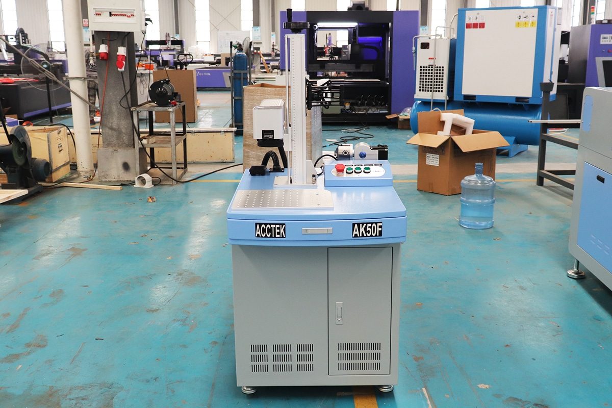
How Do Laser Parameters Affect The Marking Effect?
Laser marking is a non-contact manufacturing process that uses a concentrated laser beam to create permanent text, serial numbers, barcodes, logos, patterns, and functional surface features on a wide range of materials. Unlike printing or mechanical engraving, laser marking does not normally require inks, cutting tools, or direct physical contact with the workpiece. However, the final marking effect depends heavily on how the laser parameters are selected and coordinated.
Laser power, marking speed, pulse frequency, pulse width, hatch spacing, focal position, spot size, scanning strategy, and the number of marking passes all influence the amount of energy delivered to the material. These parameters determine whether the laser causes color change, oxidation, carbonization, foaming, melting, ablation, engraving, or surface texturing. Even a small parameter adjustment can noticeably change the mark’s darkness, depth, edge definition, contrast, surface roughness, heat-affected zone, and overall consistency.
The relationship between laser parameters and marking quality is not based on a single setting. Increasing power may produce a darker or deeper mark, but excessive power can also cause burning, deformation, discoloration, or excessive material removal. Reducing marking speed increases energy exposure, yet moving too slowly may widen the mark and damage the surrounding surface. Similarly, pulse frequency and pulse width affect peak power, pulse overlap, thermal accumulation, and the way energy interacts with the material.
Material characteristics must also be considered. Metals, plastics, ceramics, coated surfaces, and organic materials absorb and respond to laser energy differently. A parameter combination that produces a high-contrast mark on stainless steel may create poor contrast or thermal damage on aluminum or plastic.
Understanding how individual laser parameters interact is therefore essential for achieving stable, repeatable, and application-specific marking results. Proper parameter optimization improves mark quality, increases production efficiency, reduces scrap, protects the workpiece, and helps extend the service life of optical and mechanical components.
Table of Contents
Understanding the Laser Marking Effect
The laser marking effect refers to the visible, physical, and functional changes created when laser energy interacts with the surface of a material. Depending on the laser source, processing parameters, and material properties, the laser may produce discoloration, oxidation, carbonization, foaming, melting, ablation, engraving, or microscopic surface restructuring. The resulting mark can range from a shallow color change with almost no measurable material removal to a deep, permanent engraving designed to withstand severe wear.
Evaluating laser marks involves more than checking whether it looks dark or visually attractive. A successful mark must meet the requirements of its intended application. A decorative logo may prioritize smooth appearance and uniform color, while a data matrix code on an industrial component must remain machine-readable throughout the product’s service life. A depth-marked serial number may need to survive painting, abrasion, chemical cleaning, or exposure to high temperatures. For these reasons, the marking effect should be assessed through several interconnected quality characteristics.
Marking contrast, depth, edge definition, surface roughness, heat-affected zone, permanence, and readability are among the most important indicators. Each characteristic is influenced by laser power, marking speed, pulse frequency, pulse width, focal position, hatch spacing, scanning pattern, and the number of marking passes. Improving one characteristic may sometimes reduce another. For example, increasing energy input may improve depth but enlarge the heat-affected zone and reduce edge sharpness. Understanding these relationships is essential for selecting parameters that produce a balanced and reliable result.
Marking Contrast
Marking contrast describes the difference in brightness, color, or reflectivity between the marked area and the surrounding unmarked surface. High contrast makes text, logos, serial numbers, and machine-readable codes easier to identify. However, the darkest possible mark is not always the best result. The required contrast depends on the material, lighting conditions, inspection method, and intended application.
On metals, contrast may be created through oxidation, annealing, surface melting, roughening, or material removal. Stainless steel, for example, can produce black, blue, brown, or other colored marks when controlled heating creates a thin oxide layer. Aluminum may produce light or dark marks depending on its coating, alloy composition, and surface finish. On plastics, contrast can result from carbonization, foaming, pigment modification, or chemical changes in additives.
Laser power and marking speed strongly affect contrast because they determine the energy delivered per unit area. Low power or excessively high speed may create a faint, incomplete mark. Increasing power or reducing speed generally increases energy exposure and may darken the result. However, excessive energy can burn the surface, remove the contrast-producing layer, create an uneven color, or damage heat-sensitive materials.
Pulse frequency and pulse width also influence contrast by controlling how energy is distributed. A high frequency may increase pulse overlap and produce a smoother, more uniform appearance, while a lower frequency may generate stronger individual pulses that cause more aggressive ablation. Hatch spacing affects whether adjacent scan lines overlap sufficiently. Excessive spacing can leave visible gaps, while overly dense spacing can cause thermal accumulation and unwanted discoloration.
The surrounding surface condition must also be considered. A dark mark on a polished surface may provide excellent visual contrast, while the same mark on a rough or oxidized surface may be difficult to distinguish. Consistent cleaning, focusing, and material preparation are therefore important for maintaining uniform contrast across production batches.
Marking Depth
Marking depth refers to the vertical amount of material removed, displaced, melted, or restructured during the marking process. Shallow marking may produce only a visible surface change, while deep engraving creates a measurable recess in the workpiece. The required depth depends on whether the mark is decorative, informational, traceable, functional, or intended to survive later manufacturing processes.
Laser power is a major factor in determining depth. Higher average power generally increases the amount of energy available for material removal. Nevertheless, power alone does not determine the result. Marking speed, pulse energy, pulse duration, repetition rate, spot size, and the number of passes all affect how much material is removed.
Slower marking speeds increase the interaction time between the laser and the workpiece. This usually produces deeper marks because more pulses are delivered to each area. Repeated passes can also increase depth while providing greater control than attempting to remove a large amount of material in one pass. Multiple moderate-energy passes often produce cleaner results than a single extremely aggressive pass.
Pulse width has a particularly important influence on depth and thermal behavior. Shorter pulses can generate high peak power and remove material rapidly with limited heat diffusion. Longer pulses deliver energy over a greater period, which can increase melting and thermal effects. The most suitable pulse width depends on whether the goal is precise ablation, deep engraving, smooth melting, or color change.
Focal position must also be adjusted as the mark becomes deeper. When engraving a deep cavity, the original surface gradually moves away from the optimal focal plane. Without focus compensation, energy density decreases, and the bottom of the engraving may become uneven. Deep marking applications may therefore require staged focusing, dynamic focus control, or carefully planned layer-by-layer processing.
Excessive depth can create problems such as wide grooves, recast material, cracking, deformation, sharp edges, and long processing times. The objective should be to achieve the minimum depth needed for permanence and functionality without unnecessarily weakening or damaging the component.
Edge Definition
Edge definition describes the sharpness, accuracy, and cleanliness of the boundary between the marked and unmarked areas. Well-defined edges are important for small text, detailed logos, fine graphics, barcodes, QR codes, data matrix codes, and precision scale markings. Poor edge definition can make characters appear blurred, widened, irregular, or incomplete.
The laser spot size is one of the primary factors controlling edge definition. A smaller focused spot can produce finer details and narrower lines. However, a small spot also creates higher energy density, which may increase melting or burning if other parameters are not adjusted. Lens selection, beam quality, focal distance, and correct focusing all influence the achievable spot size.
Marking speed affects the stability and continuity of edges. If the speed is too high, corners and thin lines may be incomplete because insufficient energy reaches the material. If the speed is too low, excessive heating can cause the edges to spread beyond the intended boundary. Scanner acceleration, deceleration, and corner delays can also create uneven energy distribution, especially around tight curves or sharp changes in direction.
Pulse overlap must be carefully controlled. Insufficient overlap can create dotted, serrated, or discontinuous edges. Excessive overlap may widen the line and generate a larger heat-affected area. Pulse frequency should therefore be coordinated with marking speed so that adjacent pulses create a continuous mark without excessive thermal accumulation.
Hatch patterns influence edge quality in filled graphics. Scan lines extending beyond the outline may create a halo or rough boundary, while inadequate fill compensation can leave gaps near the perimeter. Contour passes are often added before or after filling to sharpen the boundary and improve visual precision.
Mechanical stability, scanner calibration, workpiece positioning, and surface flatness also affect edge definition. Vibration, incorrect scaling, field distortion, or inconsistent focal distance can reduce dimensional accuracy even when the laser parameters are theoretically correct.
Surface Roughness
Surface roughness refers to the microscopic irregularities left on the marked area after laser processing. The surface may become smoother, rougher, pitted, textured, melted, or covered with redeposited material. Roughness influences appearance, tactile feel, reflectivity, coating adhesion, friction, cleanliness, and corrosion behavior.
Low-energy color marking may produce little change in surface roughness because it primarily modifies the oxide layer or molecular structure. Engraving and ablation generally increase roughness by removing material and creating microscopic cavities. Melting can either smooth the surface through reflow or create irregular ridges when molten material resolidifies.
High pulse energy and low repetition rates often produce aggressive material removal and pronounced surface texture. Higher repetition rates with lower energy per pulse may create a more uniform finish, although excessive pulse overlap can cause heat buildup and molten debris. Short pulse durations usually reduce the amount of molten material, helping create cleaner microstructures. Longer pulses tend to promote melting, recast layers, and broader thermal modification.
Hatch spacing and scanning strategy are important for controlling texture. Closely spaced scan lines create more overlap and may smooth the marked area, but excessive overlap can increase thermal damage. Wider spacing may leave visible grooves between scan paths. Cross-hatching, in which successive layers are marked at different angles, can improve uniformity and reduce directional surface patterns.
The number of passes also influences roughness. Repeated engraving passes can deepen the mark but may leave debris and irregular sidewalls. A final low-energy cleaning or polishing pass is sometimes used to remove residue and improve surface consistency. Air assistance or extraction can further reduce redeposition by removing vaporized particles and smoke from the processing area.
Surface roughness should be matched to the application. Decorative parts may require a smooth, visually uniform mark, while bonding, coating, or friction-control applications may intentionally use laser texturing to create a specific roughness.
Heat-Affected Zone
The heat-affected zone is the area surrounding the visible mark where the material has experienced thermal changes without necessarily being removed. These changes may include discoloration, oxidation, softening, hardening, residual stress, microcracking, deformation, or alteration of the material’s microstructure.
The size of the heat-affected zone depends on the total energy input and the rate at which heat spreads through the material. High power, slow marking speed, long pulse width, dense hatch spacing, and repeated passes can all increase thermal accumulation. Materials with high thermal conductivity spread heat rapidly, while low-conductivity materials may retain heat near the marking area.
Pulse duration is especially important. Very short pulses deliver energy faster than heat can diffuse deeply into the workpiece. This can remove material with a relatively small heat-affected zone. Longer pulses provide more time for thermal conduction, increasing the likelihood of melting, discoloration, and surrounding damage.
The interval between pulses and scan lines also affects cooling. High pulse frequencies and tightly spaced hatch lines may repeatedly heat the same region before it has time to cool. Alternating scan directions, dividing the design into sections, adding cooling delays, or using multiple lighter passes can help limit heat accumulation.
A large heat-affected zone may be acceptable when annealing stainless steel to produce dark contrast without removing material. In other applications, it can be undesirable. Heat-sensitive plastics may warp, bubble, discolor, or release gas. Thin metal parts may distort, and hardened components may undergo local changes in mechanical properties.
Controlling the heat-affected zone requires balancing energy density with processing time. The goal is to deliver enough energy to create the required mark while minimizing unwanted thermal changes beyond the intended area.
Marking Permanence
Marking permanence refers to the ability of a mark to remain identifiable throughout the expected service life of the product. A permanent mark should resist abrasion, corrosion, chemicals, ultraviolet exposure, cleaning, heat, moisture, and normal handling, depending on the operating environment.
The most permanent marks are generally created through direct material modification or removal. Deep engraving remains visible even if the surface experiences wear or receives a coating. Annealed marks can be durable because the color is created within an oxide layer rather than deposited as ink. However, their corrosion resistance depends on the material, oxide structure, and processing conditions.
Marks created only through superficial discoloration may fade or become difficult to read if the surface is polished, scratched, or exposed to chemicals. Foamed plastic marks can provide strong contrast but may be less resistant to abrasion than subsurface color changes. Coated materials may produce attractive marks by removing the top coating, but the result depends on the durability of the remaining substrate and coating edges.
Laser parameters influence permanence by controlling the depth and type of modification. Insufficient energy may produce a weak mark that can be rubbed away or lost during cleaning. Excessive energy may reduce permanence by causing cracks, loose debris, corrosion-prone surfaces, or poor adhesion around the marked area.
The intended post-processing steps must also be considered. Marks applied before painting, coating, anodizing, heat treatment, or shot blasting may need additional depth. In contrast, marks placed on finished surfaces may prioritize minimal material damage and controlled contrast.
Permanence should be validated through application-specific testing rather than visual inspection alone. Abrasion tests, chemical exposure tests, salt-spray testing, thermal cycling, and accelerated weathering can be used to determine whether the selected parameters provide sufficient durability.
Readability and Verification
Readability describes how easily a human or machine can recognize and interpret a laser mark. Verification goes further by measuring whether the mark meets defined quality standards. This is especially important for barcodes, QR codes, data matrix codes, unique identifiers, serial numbers, and traceability information.
Human-readable text requires suitable contrast, character size, line width, spacing, and edge definition. Very deep marking is not automatically more readable. Excessive depth can create shadows, uneven reflections, or debris that reduces visual clarity. Similarly, an extremely dark mark may still be difficult to read if its edges are blurred or its surface is highly reflective.
Machine-readable codes depend on consistent cell geometry and a clear distinction between marked and unmarked areas. Laser power, speed, focus, pulse frequency, and hatch settings must produce uniform cells without excessive growth or shrinkage. Overexposure may cause adjacent cells to merge, while underexposure may leave incomplete or low-contrast modules.
Surface curvature and reflectivity can make verification more difficult. Highly polished metals may create glare, while cylindrical or uneven components may cause inconsistent focusing. Appropriate lighting, camera angles, code orientation, and marking placement should therefore be considered during process development.
Verification systems evaluate characteristics such as contrast, modulation, cell size, axial nonuniformity, grid distortion, fixed-pattern damage, and unused error correction. A code may appear acceptable to the human eye but still receive a poor verification grade because of geometric distortion or inconsistent contrast.
Reliable readability requires both stable marking parameters and controlled inspection conditions. Parameter development should include testing with the same scanners, cameras, and lighting that will be used in production. This ensures that the mark is not only visually acceptable but also consistently readable throughout manufacturing, distribution, and service.
The laser marking effect is a combination of visual quality, physical modification, dimensional accuracy, thermal influence, durability, and readability. Marking contrast determines how clearly the mark stands out from the surrounding surface, while marking depth influences resistance to wear and later processing. Edge definition is essential for fine graphics and small characters, and surface roughness affects appearance, functionality, reflectivity, and coating behavior.
The heat-affected zone shows how far thermal energy spreads beyond the intended mark. It must be controlled carefully to prevent discoloration, deformation, cracking, or changes in material properties. Marking permanence determines whether the information remains identifiable under abrasion, corrosion, chemicals, heat, and environmental exposure. Readability and verification confirm that the mark can be reliably interpreted by both people and automated identification systems.
These quality characteristics are closely connected. Increasing energy input may improve contrast, depth, or permanence, but it may also increase roughness, widen edges, and enlarge the heat-affected zone. Reducing energy can improve precision and surface appearance but may result in weak contrast or insufficient durability. There is therefore no single laser parameter that independently determines marking quality.
Achieving the desired marking effect requires balancing laser power, speed, pulse characteristics, focus, hatch spacing, scanning strategy, and pass count according to the material and application. The best parameter combination is the one that satisfies all essential quality requirements while maintaining stable production speed, low rejection rates, and minimal damage to the workpiece.
How Laser Parameters Work Together
Laser marking parameters do not operate independently. The final marking effect is produced by the combined influence of laser power, pulse frequency, pulse width, marking speed, spot size, hatch spacing, focal position, and the number of processing passes. Changing one parameter often alters the practical effect of several others. For example, increasing average power may raise the energy delivered to the material, but the actual result will also depend on how that power is divided among individual pulses, how closely those pulses overlap, and how the scan lines are arranged.
Understanding these interactions is more useful than evaluating each machine setting in isolation. Two parameter combinations with the same average power can produce very different marks if they have different pulse energies or peak powers. Similarly, two processes with similar energy density may generate different levels of melting, ablation, oxidation, or thermal damage because the energy is delivered over different time scales.
Several calculated relationships help explain how laser parameters work together. Energy density describes how much energy is concentrated within a given area. Pulse energy describes the energy contained in each laser pulse. Peak power indicates how intensely that pulse delivers its energy. Pulse overlap determines how many pulses interact with the same point along a scanning path, while line overlap determines how adjacent hatch lines interact across a filled marking area.
These relationships influence marking contrast, depth, surface roughness, edge definition, heat accumulation, and processing speed. A stable marking process therefore requires more than increasing or decreasing a single value. The parameters must be balanced so that the laser delivers the correct amount of energy, at the correct intensity, with the correct spatial distribution and timing.
Energy Density
Energy density, often called fluence when discussing pulsed lasers, represents the amount of laser energy delivered to a unit area of the workpiece. It is one of the most useful concepts for understanding whether the laser will heat, discolor, melt, vaporize, or remove a material.
For a single laser pulse, fluence can be expressed approximately as: Fluence = Pulse Energy ÷ Laser Spot Area
For a continuous scanning process, practical energy input per unit area is influenced by average laser power, marking speed, spot size, hatch spacing, and the number of passes. Higher average power, slower marking speed, smaller hatch spacing, or additional passes generally increase the accumulated energy density.
Every material has characteristic energy thresholds. Below the modification threshold, the laser may produce little or no visible effect. Once sufficient energy density is reached, the material may begin to change color, oxidize, foam, melt, or ablate. At still higher levels, the process may produce deeper engraving, extensive melting, burning, cracking, or deformation.
This threshold behavior explains why small parameter changes can sometimes cause a large difference in appearance. A slight reduction in marking speed may move the process from weak discoloration to strong oxidation. A small increase in pulse energy may change the result from surface heating to material removal.
Energy density is strongly affected by laser spot size. When the same amount of energy is focused into a smaller spot, the energy concentration increases. This can improve fine-detail marking and increase ablation efficiency. However, it may also create excessive local heating, deep pits, or irregular edges. A larger spot spreads the energy over a wider area, producing lower energy density and potentially smoother but less intense marking.
Focal position therefore has a direct effect on energy density. At the correct focal plane, the laser normally reaches its smallest spot and highest energy concentration. Moving the workpiece above or below focus enlarges the spot and lowers the energy density. Slight defocusing may be useful when a wider, smoother, or less aggressive mark is desired, but excessive defocusing can produce poor contrast and blurred details.
Marking speed changes the amount of time the beam interacts with a given area. Slower movement exposes each location to more pulses and increases accumulated energy. Faster movement reduces interaction time and may produce a lighter or shallower mark. The relationship is not always perfectly linear because pulse overlap, thermal diffusion, and scanner dynamics also change the result.
Hatch spacing controls the energy distribution across filled areas. Closely spaced hatch lines increase line overlap and expose the material to more energy. This often improves fill uniformity and marking darkness, but it can also increase heat accumulation. Wider spacing reduces processing time and thermal input, although excessive spacing may leave visible unmarked gaps.
Energy density is useful for comparing parameter settings, but it does not fully describe the marking process. The same total energy density can be delivered through a small number of powerful pulses or a large number of weaker pulses. These two conditions may produce very different material responses. Pulse energy and peak power must therefore also be considered.
Pulse Energy
Pulse energy is the amount of laser energy contained in an individual pulse. For a pulsed laser, it can be estimated using the relationship: Pulse Energy = Average Laser Power ÷ Pulse Frequency
For example, when average power remains constant, reducing the pulse frequency increases the energy of each pulse because the available power is divided among fewer pulses. Increasing the frequency reduces the energy per pulse because the same average output is distributed across a greater number of pulses.
Pulse energy is especially important in fiber, MOPA, ultraviolet, green, and other pulsed laser marking systems. It helps determine whether each pulse produces gentle heating, surface modification, melting, or aggressive material removal.
High pulse energy can create strong instantaneous interaction with the surface. It may improve engraving depth, remove coatings more efficiently, or produce stronger contrast on materials that require high ablation intensity. However, excessive pulse energy can create deep craters, rough surfaces, molten spatter, edge chipping, or damage to thin and fragile parts.
Low pulse energy generally produces a gentler material response. It may be suitable for annealing, color change, delicate plastic marking, thin coating removal, or applications requiring limited surface disruption. Nevertheless, if pulse energy is too low, the laser may not exceed the material’s modification threshold, resulting in weak contrast or incomplete marking.
Pulse frequency must therefore be selected together with average power. Raising frequency does not simply make the process faster. It increases the number of pulses generated each second but normally reduces the energy available in each pulse when average power is unchanged. A high-frequency process may create a smooth, uniform mark because many low-energy pulses overlap. A lower-frequency process may create stronger individual impacts and more pronounced surface texture.
The optimum pulse energy depends on the material and the required effect. Deep engraving of metals generally benefits from sufficient pulse energy to remove material effectively. Annealing stainless steel may require controlled thermal input without aggressive ablation. Plastic marking may need carefully limited pulse energy to avoid carbonization, bubbling, or deformation.
Pulse energy is also influenced by the laser source’s operating limits. Some lasers cannot maintain their rated average power across the entire frequency range. At frequencies below or above the recommended operating range, pulse energy or output stability may change unexpectedly. Parameter development should therefore consider the laser source’s power-frequency curve rather than relying only on nominal settings.
When multiple passes are used, moderate pulse energy may produce better results than extreme pulse energy. Several controlled passes allow heat and debris to be managed more effectively. They may create cleaner sidewalls, more uniform depth, and less recast material than a single aggressive pass.
Pulse energy explains how much energy each pulse carries, but it does not describe how quickly that energy is released. For that, peak power must be considered.
Peak Power
Peak power is the maximum power reached during a laser pulse. It represents the intensity of energy delivery over a very short period. An approximate relationship is: Peak Power = Pulse Energy ÷ Pulse Width
A pulse containing a given amount of energy will have a higher peak power when its pulse width is shorter. If the same energy is delivered over a longer pulse duration, peak power decreases.
Peak power plays a major role in determining how strongly the laser interacts with the material. High peak power can exceed the ablation threshold rapidly, causing material to vaporize or be ejected before a large amount of heat spreads into the surrounding area. This is why short-pulse lasers are often used for precision marking, micro-engraving, and applications requiring a relatively small heat-affected zone.
Lower peak power with longer pulse duration tends to produce more sustained heating. Instead of rapidly removing material, the pulse may cause greater melting, thermal diffusion, oxidation, or carbonization. This behavior can be useful for annealing metals, creating dark marks, foaming plastics, or producing smooth thermal effects.
Peak power should not be confused with average power. A pulsed laser with modest average power can produce extremely high peak power because its energy is concentrated into short pulses. Conversely, a laser with high average power may have lower peak intensity if the energy is delivered continuously or through longer pulses.
Shortening the pulse width while maintaining pulse energy increases peak power. This may improve ablation efficiency and edge definition, but it can also create rough pits or excessive material ejection if the peak intensity becomes too high. Lengthening the pulse width lowers peak power and increases the time available for heat conduction, which may enlarge the heat-affected zone.
In MOPA fiber laser marking systems, adjustable pulse width provides greater control over peak power and thermal behavior. Short pulse widths are commonly selected for precise material removal, fine engraving, and reduced heat input. Longer pulse widths may be chosen for black marking on anodized aluminum, color marking on stainless steel, or applications that depend on controlled thermal modification.
Peak power also affects plasma formation and shielding. When pulse intensity is extremely high, vaporized material above the surface may form a plasma plume. This plume can absorb or scatter part of the incoming laser energy, reducing process efficiency and creating inconsistent results. Adequate pulse spacing, extraction, and parameter control can help minimize this effect.
The ideal peak power is therefore not necessarily the highest available value. It must be sufficient to initiate the desired material response without causing uncontrolled ablation, excessive roughness, cracking, or debris formation.
Pulse Overlap
Pulse overlap describes how much consecutive laser pulses overlap along the direction of beam movement. It is determined by the laser spot diameter, pulse frequency, and marking speed.
The distance between consecutive pulses can be estimated as: Pulse Spacing = Marking Speed ÷ Pulse Frequency
When pulse spacing is smaller than the laser spot diameter, the pulses overlap. When it is approximately equal to the spot diameter, adjacent pulses just meet. When pulse spacing is larger than the spot diameter, gaps may appear between pulse locations.
Pulse overlap can be expressed conceptually as the percentage of the spot diameter covered by the next pulse. A high overlap means that each area of the material receives energy from several pulses. A low overlap means that fewer pulses interact with each point.
Increasing pulse frequency while maintaining the same marking speed increases pulse overlap. Reducing marking speed while maintaining frequency produces the same general effect. Conversely, reducing frequency or increasing speed decreases overlap.
Insufficient pulse overlap often produces dotted, broken, or uneven lines. The individual pulse impressions may be visible, and fine details may appear serrated. This condition is especially problematic for small text, thin graphics, and machine-readable codes that require continuous, sharply defined boundaries.
Moderate pulse overlap generally creates smooth and continuous lines. Successive pulses blend, improving contrast uniformity and edge consistency. This is often desirable for general-purpose marking.
Excessive pulse overlap can expose the same area to too many pulses. The resulting heat accumulation may widen the mark, increase surface roughness, cause melting, enlarge the heat-affected zone, or reduce processing efficiency. On plastics, high overlap can cause bubbling, burning, or deformation. On metals, it may create deep grooves, recast material, or excessive oxidation.
Pulse overlap also interacts with pulse energy. A high overlap combined with high pulse energy creates a much more aggressive process than either condition alone. A high-frequency setting may appear thermally gentle because the energy per pulse is lower, but very dense overlap can still produce substantial accumulated heating.
Likewise, low-frequency pulses may contain more energy individually. Even with relatively low overlap, they can create deep craters or strong material removal. The final effect depends on both the intensity of each pulse and the number of pulses delivered to each location.
For curved paths and sharp corners, actual pulse overlap may become higher than expected. Galvanometer scanners decelerate when changing direction, causing more pulses to accumulate around corners. This can produce darker corners, wider line ends, or local burning. Corner delay, jump delay, and scanner compensation settings may need adjustment to maintain uniform exposure.
Pulse overlap should be optimized according to the desired mark. Fine, smooth graphics usually require sufficient overlap to eliminate gaps. Deep engraving may use lower overlap with higher-energy pulses to improve material ejection. Thermal color marking may use carefully controlled high overlap to build a uniform oxide layer.
Line Overlap
Line overlap refers to the interaction between neighboring scan lines used to fill a marked area. It is primarily controlled by hatch spacing and laser spot diameter. While pulse overlap occurs along the scanning direction, line overlap occurs perpendicular to that direction.
When hatch spacing is smaller than the effective laser spot diameter, adjacent lines overlap. When the spacing is equal to the spot diameter, the lines approximately meet. When the spacing is wider than the spot diameter, gaps may remain between the lines.
Dense line overlap can create a solid, uniform fill. It is often used to produce dark logos, filled characters, engraved backgrounds, and high-contrast codes. Each region receives energy from multiple neighboring scan lines, helping eliminate visible striping.
However, reducing hatch spacing also increases the number of scan lines required to fill the design. This increases marking time and accumulated energy. If the lines are too closely spaced, the material may overheat, melt, discolor, warp, or develop an excessively rough surface.
Wide hatch spacing reduces processing time and thermal input. It may be suitable when a light texture or fast mark is acceptable. If the spacing is too wide, however, the fill may look striped, uneven, or incomplete. Small barcode cells and thin graphic features may contain unmarked gaps that reduce readability.
Line overlap must be coordinated with marking speed and pulse overlap. A process can have high pulse overlap along each line but low line overlap between adjacent lines. This may produce smooth individual scan lines with visible spaces between them. Conversely, dense line overlap with insufficient pulse overlap may create filled areas composed of dotted or discontinuous tracks.
Hatch angle also influences the appearance and uniformity of line overlap. A single hatch direction can create directional texture and reflect light differently depending on the viewing angle. Cross-hatching uses two or more passes at different angles, such as 0 and 90 degrees or 45 and 135 degrees. This can improve coverage, reduce directional roughness, and produce more uniform engraving.
Rotating the hatch angle between passes can also improve deep engraving. Repeatedly scanning in the same direction may form grooves that interfere with debris removal. Alternating directions distributes energy more evenly and reduces the buildup of ridges.
Contour passes interact with hatch lines as well. A filled design may use internal hatch lines followed by an outline pass to improve edge definition. If the hatch lines extend too far into the contour, excessive overlap near the perimeter may create a dark border or a deeper edge. If they stop too far from the contour, a visible unmarked gap may appear.
Complex graphics may require different hatch settings for different regions. Large filled areas can tolerate wider spacing, while small characters and detailed codes may require finer spacing. Applying one hatch value to every feature may cause unnecessary processing time or inconsistent quality.
Material properties must also be considered. Highly conductive metals may dissipate heat quickly and tolerate denser line overlap. Heat-sensitive plastics, thin films, painted surfaces, and electronic components may require wider spacing or alternating scan sequences to prevent damage.
Laser parameters work together by controlling how energy is distributed in time and across the surface of the material. Energy density indicates the amount of energy applied to a given area and helps determine whether the material is heated, modified, melted, or removed. Pulse energy defines how much energy is contained in each pulse, while peak power describes how rapidly that energy is delivered.
These values are closely connected. At a constant average power, reducing pulse frequency normally increases pulse energy. Shortening pulse width increases peak power when pulse energy remains similar. A smaller focused spot raises energy density, while slower marking speed increases the number of pulses delivered to each location.
Pulse overlap controls how consecutive pulses interact along a scanning path. Insufficient overlap may create dotted or discontinuous lines, while excessive overlap can cause thermal accumulation and surface damage. Line overlap controls the relationship between adjacent hatch lines. Proper line overlap produces uniform filled areas, whereas inadequate spacing control can cause gaps, striping, overheating, or unnecessarily long processing times.
No single calculated value can fully predict the final marking effect. Two processes with similar average power or total energy density may behave differently because they use different pulse energies, peak powers, pulse widths, or overlap levels. The material’s absorption, thermal conductivity, surface condition, thickness, and modification threshold further influence the result.
Effective parameter optimization therefore requires balancing energy density, pulse energy, peak power, pulse overlap, and line overlap as an integrated system. The objective is to exceed the threshold needed for the intended marking mechanism while avoiding unnecessary melting, burning, deformation, debris, or heat damage. When these relationships are properly controlled, the laser can produce stable contrast, accurate depth, sharp edges, uniform texture, limited heat influence, and consistently readable marks.
Laser Power
Laser power is one of the most influential parameters in laser marking because it determines the average amount of optical energy available for interaction with the workpiece. It is commonly expressed in watts and is usually set as a percentage of the laser source’s rated output in the marking software. Increasing the power setting generally increases the energy delivered to the material, but the actual marking effect also depends on marking speed, pulse frequency, pulse width, spot size, focal position, hatch spacing, and the number of passes.
Power should therefore not be evaluated as an isolated setting. A high-power laser operating at high speed may deliver less energy to each point than a lower-power laser moving slowly. In pulsed systems, the same average power can also be divided into many low-energy pulses or fewer high-energy pulses, producing very different surface reactions. The relationship between power and marking quality is therefore governed by both the total energy input and the way that energy is distributed.
Correct power selection allows the laser to exceed the material’s modification threshold and create the intended effect, such as discoloration, annealing, foaming, carbonization, coating removal, ablation, or deep engraving. Too much power can cause burning, melting, deformation, excessive roughness, or a large heat-affected zone. Too little power may produce faint, incomplete, or temporary marks.
Material absorption and reflectivity also influence how much of the emitted laser power is actually used. A material that absorbs the laser wavelength efficiently may require relatively low power, while a highly reflective material may initially require greater intensity or specialized wavelength control. In addition, stable laser output is essential because fluctuations in power can lead to inconsistent contrast, depth, line width, and readability.
Effect of Increasing Laser Power
Increasing laser power generally raises the amount of energy delivered to the material during marking. When other parameters remain unchanged, this can strengthen the interaction between the laser beam and the workpiece. The mark may become darker, deeper, wider, rougher, or more thermally affected, depending on the material and marking mechanism.
At relatively low power levels, increasing power may improve a faint or incomplete mark. More energy allows the material to reach the temperature or energy threshold required for visible modification. On metals, this may promote oxidation, surface melting, or ablation. On plastics, it may increase foaming, carbonization, pigment change, or molecular modification. On coated materials, it may help remove the surface layer more completely and expose the contrasting substrate beneath it.
For engraving applications, higher power can increase material removal per pass. The laser supplies more energy to melt or vaporize the surface, allowing greater depth to be achieved at the same marking speed. This can reduce the number of passes required for a specified engraving depth. However, the increase in depth is not always proportional to the increase in power. As material is removed, some energy is lost through reflection, heat conduction, plasma formation, debris shielding, and inefficient melt ejection.
Increasing power can also improve marking speed. A process that produces the required result at moderate power and low speed may sometimes be accelerated by raising the power. The higher energy input can compensate for the shorter interaction time. This approach can improve productivity, provided that the laser source, scanner, material, and extraction system can support the more intensive process.
In annealing applications, increasing power raises the surface temperature and can intensify oxide formation. On stainless steel and certain other alloys, this may create darker or differently colored marks. However, annealing requires careful thermal control. If power becomes high enough to remove material rather than only heat it, the process may change from smooth color marking to rough engraving.
On plastics, moderate increases in power can strengthen contrast. Light-colored plastics may darken through carbonization, while dark plastics may become lighter through foaming. The correct result depends on the polymer composition, additives, pigments, and laser wavelength. A small increase in power may create a large visual change once the material reaches its reaction threshold.
Laser power also influences line width. A stronger beam may affect not only the center of the focused spot but also the lower-intensity outer regions. As a result, marked lines can become wider even when the spot size and scanner path remain unchanged. This effect must be considered when marking small characters, thin lines, or machine-readable codes.
The effect of increasing power is strongly related to marking speed. At slow speed, even a modest power increase can cause substantial heat accumulation. At high speed, the same increase may only produce a slight improvement in contrast. Power should therefore be adjusted together with speed rather than optimized independently.
Pulse frequency also changes how higher average power behaves. At a fixed frequency, increasing average power often raises pulse energy. Each pulse may then remove more material or create a stronger thermal response. At a high frequency, the additional power may be distributed among many pulses, producing smoother but more accumulated heating.
Pulse width further influences the result. Short pulses can convert increased power into higher peak intensity and more efficient ablation. Longer pulses deliver the energy over a greater period, encouraging heat conduction, melting, and oxidation. Therefore, the same increase in average power can produce either cleaner material removal or more serious thermal damage depending on the pulse characteristics.
Increasing power can be beneficial when the original setting is below the effective processing range. It can improve contrast, depth, speed, permanence, and coating-removal efficiency. Nevertheless, power should be increased gradually while inspecting the complete mark. A visually darker result does not necessarily mean a technically better mark if edge quality, surface integrity, code readability, or corrosion resistance has deteriorated.
Problems Caused by Excessive Power
Excessive laser power occurs when the energy delivered to the material is greater than necessary for the intended marking effect. The consequences depend on the workpiece, laser type, pulse characteristics, and other settings, but common problems include burning, melting, roughness, deformation, discoloration, debris, and loss of detail.
One of the most obvious effects is excessive material removal. Instead of creating a controlled surface mark, the laser may form deep craters or irregular grooves. This can make the marked area rough and uneven. In filled graphics, some regions may become deeper than others because of scanner deceleration, hatch-line overlap, or repeated exposure near boundaries.
Excessive power can widen lines and reduce edge definition. The outer portion of the beam may exceed the material’s modification threshold, enlarging the affected area beyond the intended path. Small characters can become thick or blurred, and gaps between barcode or data matrix cells may partially close. This can reduce readability even when the mark appears dark to the human eye.
High power can also create excessive melting. Molten material may flow to the sides of the marked line and resolidify as ridges or recast layers. These deposits can make the surface rough and alter the apparent dimensions of fine features. In deep engraving, molten material may remain inside the cavity and reduce effective depth.
Spatter and redeposited debris are additional concerns. Rapid vaporization can eject particles from the surface. Some particles may settle back onto the workpiece, lens protection window, scanner enclosure, or nearby equipment. Deposited debris can reduce cosmetic quality and may require additional cleaning. Accumulation on optical components can gradually reduce transmitted power and increase the risk of damage.
Excessive power often enlarges the heat-affected zone. Surrounding material may experience oxidation, discoloration, softening, hardening, or microstructural change. Thin metal sheets can warp, and precision components may lose dimensional accuracy. Hardened or heat-treated parts may undergo localized changes in mechanical properties.
On stainless steel, power that is too high can damage the passive surface layer and reduce corrosion resistance. A mark may appear dark and durable but leave behind a rough, chromium-depleted, or contamination-prone surface. Where corrosion performance is important, parameter validation should include appropriate exposure or corrosion testing.
On aluminum, excessive energy can produce rough craters, heavy oxidation, or an uneven white appearance. Anodized aluminum may suffer damage beyond the intended coating layer, exposing or melting the underlying metal. Thin anodized coatings can also develop irregular edges if the power is too high.
Plastics are particularly sensitive to excessive power. Too much energy may cause burning, bubbling, charring, cracking, warping, or gas release. The marked area can become sticky, brittle, or raised. Heat may also spread beneath the surface and deform thin walls, electronic housings, medical components, or packaging materials.
Transparent and heat-sensitive polymers may develop internal stress, haze, or microcracks. A visually acceptable mark may later fail because the material was weakened during processing. For these materials, lower power, shorter pulses, higher marking speed, or multiple light passes are often safer than one aggressive pass.
Excessive power can also reduce contrast. This may seem counterintuitive, but a surface that initially darkens can become lighter if the laser removes the contrast-producing oxide, coating, pigment, or carbonized layer. Similarly, a smooth annealed mark can turn into a bright reflective engraving when too much material is removed.
Thermal accumulation becomes especially severe when high power is combined with slow speed, high pulse frequency, narrow hatch spacing, or multiple passes. Each setting may appear reasonable by itself, but together they can create an excessive energy load. The marked area may continue heating because there is insufficient time for cooling between pulses or scan lines.
High power can reduce process stability as well. Strong vaporization may create a plume of smoke, plasma, or debris above the surface. This material can absorb or scatter incoming laser energy, leading to uneven engraving and fluctuating depth. Effective fume extraction and air assistance may reduce the problem, but parameter optimization is still necessary.
Using excessive power also places unnecessary thermal stress on the marking system. Protective windows, lenses, scanner components, and extraction filters may become contaminated or degraded more quickly. Running the source at maximum output continuously may increase cooling demand and reduce the operating margin available for maintaining stable performance.
The correct solution is not always simply to reduce power. Marking speed, pulse frequency, pulse width, focus, and hatch spacing may also need adjustment. For example, reducing power while maintaining extremely slow speed may not sufficiently reduce heat accumulation. A balanced reduction in total energy input usually produces a more stable result.
Problems Caused by Insufficient Power
Insufficient laser power means that the energy delivered to the workpiece does not reliably reach the threshold required for the intended material modification. The mark may be visible under certain lighting conditions but remain weak, inconsistent, shallow, or unsuitable for long-term use.
The most common symptom is low contrast. Text, graphics, or codes may appear faint because the material has not been heated, oxidized, foamed, carbonized, or removed sufficiently. The difference between marked and unmarked areas may be too small for easy visual recognition or automatic scanning.
Incomplete marking can also occur. Some regions may react while others remain unchanged because of variations in surface finish, coating thickness, material composition, flatness, or focus. When the process is operating close to the modification threshold, even small differences in absorption can create visible inconsistency.
Low power may produce discontinuous lines. The center of each pulse may modify the surface, but the lower-intensity regions between pulses may remain unaffected. This can create dotted or broken marks, especially when marking speed is high, or pulse overlap is low.
Engraving depth is also limited when power is insufficient. Each pass removes only a small amount of material, requiring many repetitions to achieve the target depth. This increases cycle time and may still produce an uneven cavity because debris, focal shift, and changing surface geometry reduce efficiency during later passes.
A shallow mark may lack permanence. It can become unreadable after abrasion, polishing, chemical cleaning, painting, coating, or normal product use. Traceability marks on tools, automotive components, medical devices, or industrial equipment may therefore fail their service-life requirements even though they initially appear acceptable.
Insufficient power can create poor coating removal. The laser may partially discolor or damage a coating without removing it completely. The remaining fragments can produce an uneven appearance and reduce contrast between the marked area and the substrate. Multiple passes may help, but they can also increase thermal exposure without ensuring clean removal if the pulse intensity remains below the ablation threshold.
On metals, insufficient power may fail to create a stable oxide layer for annealing. The result can be pale, nonuniform, or sensitive to viewing angle. If the process does not reach the correct temperature range, the intended black or colored mark may not develop consistently.
On plastics, low power may produce weak pigment change or incomplete foaming. The mark may appear gray rather than black or may only be visible from certain angles. Materials containing laser-sensitive additives can respond strongly at the correct threshold, but below that threshold their reaction may be minimal.
Insufficient power can also affect readability and verification. Machine-readable codes require consistent contrast and geometry across every cell. Weakly marked modules may be missed by the camera, reducing symbol contrast and modulation. A code that can be scanned under ideal lighting may fail in normal production or field conditions.
Compensating for insufficient power by reducing marking speed is possible, but this must be done carefully. Slower speed increases accumulated energy, yet it may also increase thermal diffusion. The process may shift from the desired high-intensity modification to a slower heating effect. Raising pulse energy or improving focus may be more effective in some applications.
A dirty protective window, contaminated lens, misaligned optical path, or incorrect focal position can create symptoms similar to insufficient power. The software may display a high power setting while the actual energy reaching the workpiece is much lower. Before increasing the programmed power, the condition of the optical system should be checked.
Rated laser power also does not guarantee that the full output is available at every frequency or pulse-width setting. Some pulsed lasers have an effective operating range in which output remains stable. Outside that range, actual pulse energy may fall even when the software power percentage is unchanged.
The goal is to use enough power to create a stable safety margin above the material’s processing threshold. Operating only slightly above that threshold can lead to batch-to-batch variation. However, the margin should not be so large that it causes unnecessary thermal or mechanical damage.
Power and Material Reflectivity
Material reflectivity determines how much of the incident laser energy is reflected away from the surface rather than absorbed. Only the absorbed portion contributes directly to heating, melting, ablation, or chemical modification. As a result, two materials exposed to the same laser power can respond very differently.
Reflectivity depends strongly on laser wavelength. A material may reflect a large portion of infrared energy but absorb ultraviolet or visible wavelengths more efficiently. This is why laser source selection is often as important as power selection.
Metals such as copper, brass, gold, silver, and polished aluminum are highly reflective at common infrared fiber-laser wavelengths, particularly before the surface begins to heat or change. A significant portion of the initial laser energy may be reflected, making the start of the marking process less efficient.
Once the surface becomes roughened, oxidized, melted, or heated, its absorption can increase. This creates a changing interaction during processing. The material may initially resist marking and then suddenly absorb more energy. If the power is set too high to overcome the initial reflectivity, the process may become excessively aggressive after absorption increases.
Polished surfaces are generally more reflective than rough or oxidized surfaces. A mirror-finished metal may require different parameters from the same alloy with a brushed, sandblasted, or coated surface. Surface contamination, oil, oxide, and protective films can also change absorption.
Highly reflective materials present a risk of back-reflected laser energy. Reflected radiation can travel toward the marking head or laser source. Modern systems may include optical isolators or back-reflection protection, but the risk should still be considered when processing copper, brass, silver, gold, or highly polished aluminum.
Using more power is not always the best way to mark a reflective material. A smaller spot, shorter pulse width, lower frequency, or more suitable wavelength may increase peak intensity and improve coupling without requiring excessive average power. Green and ultraviolet lasers are often selected for materials that absorb these wavelengths more effectively than near-infrared radiation.
For anodized, painted, plated, or coated materials, the surface layer may have very different reflectivity from the substrate. The coating may absorb energy efficiently and be removed at relatively low power, while the exposed metal beneath it reflects more strongly. If the power is too high, the laser may damage the substrate after the coating has been removed.
Reflectivity also influences contrast. Bright metal surfaces may provide strong contrast against a dark annealed mark, while rough surfaces scatter light and reduce the apparent difference. A deep engraving may look dark because its rough cavity reflects less light toward the observer, even if no dark oxide is present.
The angle of incidence affects reflection as well. On flat surfaces, the beam normally strikes near perpendicular to the workpiece. On curved, angled, or irregular components, some areas may receive the beam at an oblique angle. Effective absorption, spot shape, focus, and reflected-beam direction can then change across the mark.
Cylindrical and three-dimensional parts may require rotary devices, dynamic focusing, or coordinated motion to keep the beam properly aligned. Simply increasing power to compensate for angled surfaces can overprocess other regions that remain closer to normal incidence.
Reflectivity should therefore be considered during parameter development. Test samples should match the actual alloy, coating, finish, and geometry of the production part. Parameters developed on a rough sample may not transfer successfully to a polished component, even when the material specification is otherwise identical.
Power Stability
Power stability refers to the laser marking system’s ability to maintain consistent output over time and across repeated marking cycles. Stable output is necessary for producing uniform contrast, depth, line width, surface texture, and readability. Even well-developed parameters cannot provide reliable results if the actual laser power fluctuates.
Short-term power variation can create visible banding or uneven lines within a single mark. Some scan paths may appear darker or deeper than others. In machine-readable codes, variations between cells can reduce modulation and verification grades.
Long-term drift can cause marks produced at the beginning of a shift to differ from those produced later. As the laser source, optical components, scanner, and cooling system reach operating temperature, output may change. Systems that are not thermally stabilized may require a warm-up period before consistent production begins.
Temperature is a major factor in power stability. Laser sources and electronic components operate most consistently within a specified thermal range. If the cooling system cannot remove heat effectively, output power may decrease, fluctuate, or trigger protective alarms.
Water-cooled systems depend on proper coolant temperature, flow rate, cleanliness, and concentration. Blocked filters, contaminated water, pump wear, or low coolant levels can reduce cooling performance. Air-cooled systems require clean ventilation paths and adequate space around the equipment. Dust-covered fans or restricted airflow can cause internal temperatures to rise.
Optical contamination can create gradual power loss. Smoke, dust, oil, and vaporized material may collect on the protective window or lens. The contamination absorbs part of the beam, reducing the energy reaching the workpiece. It can also heat locally and permanently damage the optical component.
A contaminated optic may cause apparent instability because deposits are rarely uniform. The beam profile can become distorted, changing spot size and energy distribution. The operator may compensate by increasing the software power, which can hide the underlying problem until the contamination worsens.
Aging of the laser source can also affect output. Fiber lasers generally provide long service life, but pump diodes, optical components, power supplies, and electronic controls can gradually degrade. The actual output at a given percentage setting may slowly decline over years of use.
Power stability is also influenced by electrical supply quality. Voltage fluctuations, poor grounding, electrical noise, or overloaded circuits can affect laser and control-system performance. Industrial marking equipment should be connected according to the manufacturer’s electrical requirements, with suitable protection against unstable power.
Pulse frequency and pulse width can affect apparent power stability. Some laser sources maintain rated average power only within specified parameter ranges. At very low or very high frequencies, pulse energy may become unstable, or the source may reduce output automatically. Operators should understand the laser’s power-frequency characteristics instead of assuming that a fixed percentage always represents the same delivered power.
Marking software and controller behavior can contribute to inconsistency. Incorrect delays, scanner timing, or power ramp settings may cause the laser to emit differently at the beginning and end of lines. Corners, small circles, and densely packed features may receive more energy because the scanner slows down locally.
Power stabilization may require compensation settings such as laser-on delay, laser-off delay, corner delay, and end-of-line control. These settings coordinate laser emission with scanner movement and help prevent dark starting points, weak line ends, or overburned corners.
Regular output verification is important for critical applications. A calibrated laser power meter can be used to compare actual output with expected values. Reference samples marked at controlled intervals can also reveal changes in contrast, depth, or code quality.
Process monitoring should include more than checking the percentage displayed in the software. The programmed value represents a command, not a direct measurement of energy reaching the workpiece. Optical cleanliness, source condition, cooling performance, wavelength, pulse characteristics, and beam focus all influence the effective power.
For traceability applications, power stability should be supported by standardized operating procedures. These may include machine warm-up, daily reference marking, optical inspection, regular cleaning, coolant checks, code verification, and preventive maintenance. Consistent environmental conditions can further reduce variation.
Laser power determines the average amount of optical energy available for marking, but its effect depends on how that energy is combined with speed, frequency, pulse width, focus, hatch spacing, and pass count. Increasing power generally strengthens the material interaction and can improve contrast, engraving depth, coating removal, permanence, and processing speed.
The benefits of higher power only apply within an appropriate operating range. Excessive power can cause melting, burning, roughness, wide lines, debris, deformation, discoloration, and a larger heat-affected zone. It may also reduce code readability or remove the very surface layer responsible for producing contrast.
Insufficient power can lead to faint, incomplete, shallow, or nonpermanent marks. The process may operate too close to the material’s modification threshold, making it sensitive to variations in focus, finish, coating thickness, or composition. Low power can also create discontinuous lines, incomplete coating removal, and poor machine-readable-code verification.
Material reflectivity determines how much emitted power is actually absorbed. Highly reflective metals may require carefully controlled pulse intensity, wavelength selection, focusing, or surface preparation rather than a simple increase in average power. The material’s surface finish, coating, temperature, geometry, and angle also affect absorption.
Power stability is essential for repeatable production. Thermal drift, cooling problems, contaminated optics, source aging, electrical instability, and operation outside the recommended frequency range can all cause the delivered power to vary. Regular maintenance, output verification, optical cleaning, and process monitoring help maintain consistent marking quality.
The optimum power setting is therefore not the highest available value. It is the lowest stable level that reliably creates the required contrast, depth, permanence, and readability at the desired production speed without causing unnecessary damage to the material or marking system.
Marking Speed
Marking speed refers to the rate at which the laser beam moves across the workpiece, usually expressed in millimeters per second. It is one of the primary parameters controlling how long the laser interacts with each point on the material. Because interaction time directly affects energy input, marking speed has a strong influence on contrast, depth, line width, surface roughness, heat accumulation, and overall processing efficiency.
When laser power, pulse frequency, pulse width, spot size, and other settings remain unchanged, reducing marking speed generally increases the number of pulses and the total energy delivered to a given area. The result may be darker, deeper, wider, or more thermally affected. Increasing marking speed has the opposite effect: each location receives less exposure, which can reduce heat input and shorten cycle time but may also produce a faint, shallow, or incomplete mark.
The influence of speed cannot be evaluated independently. Its effect changes with laser power and pulse frequency. A relatively high speed may still create a strong mark when power and pulse energy are high, while a slow speed may overheat the material even at moderate power. Speed also determines the spacing between consecutive pulses and therefore affects whether the marked line appears continuous, dotted, smooth, or rough.
Actual beam speed is not constant throughout every design. Galvanometer scanners must accelerate, decelerate, change direction, and negotiate corners. Small circles, fine text, short lines, and closely spaced features can therefore receive a different amount of energy than long straight paths. Parameter optimization must account for these dynamic effects rather than relying only on the programmed speed value.
The best marking speed is not simply the fastest setting that produces a visible result. It must provide sufficient contrast, depth, permanence, and readability while limiting thermal damage and maintaining an acceptable cycle time. Achieving this balance is essential for both marking quality and production efficiency.
Effect of Reducing Marking Speed
Reducing marking speed increases the amount of time the laser beam interacts with each region of the workpiece. In pulsed systems, it also increases the number of pulses applied to each point because the beam travels a shorter distance between consecutive pulses. As a result, the accumulated energy input generally rises.
One of the most common effects of slower marking is increased contrast. A faint mark may become darker because the material receives enough energy to produce stronger oxidation, carbonization, foaming, melting, or surface removal. On stainless steel, slower movement can increase thermal exposure and help form a darker oxide layer. On plastics, it may strengthen color change or foaming, depending on the polymer and additives.
Reducing speed can also increase engraving depth. More pulses interact with each area, allowing additional material to be melted, vaporized, or ejected. This is useful when creating permanent serial numbers, identification marks, molds, tools, or components that must retain their markings after abrasion, coating, or surface treatment.
However, slower speed does not always improve engraving efficiency. When speed becomes too low, excessive heat may melt the material rather than remove it cleanly. Molten material can resolidify inside the engraving or form ridges along the edges. The mark may become deeper in some areas but rougher and less dimensionally accurate.
Line width often increases as speed decreases. The center of the beam receives more exposure, and the lower-intensity edges of the laser spot may also reach the material’s modification threshold. Thin lines can become thicker, while small gaps in text or codes may narrow or close.
Reduced speed can improve continuity when pulse overlap is initially insufficient. At high speed, consecutive pulses may be separated by visible gaps. Slowing the scanner decreases the distance between pulses, allowing their affected areas to overlap. The line becomes smoother and more continuous.
Greater overlap may also improve the uniformity of filled graphics. Closely spaced pulse locations create fewer visible individual craters or dots. Nevertheless, excessive overlap can produce uneven thermal accumulation, particularly when combined with high power, high frequency, narrow hatch spacing, or repeated passes.
One important consequence of slower marking is a larger heat-affected zone. The material has more time to absorb and conduct heat beyond the intended marking path. Metals may develop wider discoloration, oxidation, residual stress, or deformation. Thin components can warp, while hardened surfaces may undergo local changes in microstructure.
Heat-sensitive plastics may experience bubbling, burning, shrinkage, cracking, or distortion. A plastic mark may initially become darker as speed is reduced, but further reduction can cause the surface to char or melt. The best visual contrast is therefore often obtained within a relatively narrow speed range.
Slower marking can also generate more smoke, fumes, vaporized material, and debris. This may contaminate the marked surface or settle on the protective window and lens. Effective extraction becomes increasingly important as the interaction intensity rises.
In coating-removal applications, reducing speed can help remove a coating more completely. The beam has more time to break down or ablate the layer. However, once the coating has been removed, the exposed substrate may receive additional energy and become damaged. Power and speed must therefore be adjusted so that the coating is removed without excessive attack on the base material.
Annealing applications require especially careful speed control. The goal is usually to heat the surface enough to form a controlled oxide layer without removing significant material. If the beam moves too slowly, the oxide may become uneven, the surface may melt, or the corrosion resistance may be affected.
Reducing speed also increases cycle time. A design that takes only a few seconds at a high speed may take several times longer when the speed is lowered. This affects machine capacity, labor utilization, and cost per part. Slower marking should therefore be used only when it provides a measurable quality or durability benefit.
In many cases, multiple faster, lower-energy passes produce a cleaner result than a single very slow pass. Allowing some cooling between passes can reduce distortion and control depth more precisely. This strategy is particularly useful for deep engraving, sensitive plastics, thin metals, and detailed patterns.
Effect of Increasing Marking Speed
Increasing marking speed reduces the time that the laser interacts with each point on the workpiece. The beam covers more distance between pulses, and the accumulated energy per unit length or area generally decreases. This can shorten processing time and reduce thermal effects, but it may also weaken the marking result.
One of the first visible effects of higher speed is reduced contrast. The material may not receive enough energy to reach the temperature or reaction threshold required for strong discoloration, oxidation, foaming, carbonization, or ablation. The mark can appear pale, gray, incomplete, or sensitive to the viewing angle.
Increasing speed usually reduces engraving depth as well. Fewer pulses strike each location, and less material is removed. This may be acceptable for decorative or low-wear applications, but it can reduce permanence when the mark must withstand abrasion, polishing, corrosion, coating, or long-term service.
Higher speed can narrow marked lines. The outer regions of the laser spot may no longer receive enough exposure to modify the material, so only the high-intensity center contributes to the mark. This can improve fine-detail reproduction if the energy remains sufficient, but it can also make thin features disappear.
Faster movement generally reduces heat accumulation. The laser leaves each area before substantial heat can spread into the surrounding material. This can produce a smaller heat-affected zone, less discoloration, lower distortion, and reduced risk of burning.
For heat-sensitive plastics, thin films, coated surfaces, and delicate electronic parts, increasing speed may improve surface integrity. It can prevent bubbling, melting, or warping while still creating an acceptable color change. However, if speed is increased too far, the mark may become inconsistent or fail.
High speed can be particularly useful with short-pulse or high-peak-power lasers. These sources can create strong instantaneous material modification even though the interaction time is brief. The combination can produce clean ablation, limited heat diffusion, and high throughput.
Nevertheless, the scanner and laser source must be able to operate effectively at the chosen speed. At very high speeds, scanner positioning errors, delays, and acceleration limits become more significant. The programmed path may not be followed with the same precision, especially in small or complex designs.
Pulse spacing increases as marking speed rises. If the spacing becomes too large relative to the laser spot diameter, consecutive pulse impressions no longer overlap. Lines may appear dotted, broken, or serrated. Small text and machine-readable codes are especially sensitive to this problem.
Increasing pulse frequency can compensate for greater pulse spacing, but this may reduce pulse energy when average power remains constant. The process can therefore shift from a small number of strong pulses to many weaker pulses. Whether this improves the result depends on the material and marking mechanism.
Raising laser power can also compensate for higher speed by increasing the energy delivered during the shorter exposure. This is commonly used to improve productivity. However, higher power may change pulse energy, peak power, line width, and surface roughness. Simply increasing power in proportion to speed does not always reproduce the original marking effect.
At very high speeds, the laser may fail to turn on and off accurately at the beginnings and ends of short lines. Some features may become shortened or incomplete. Scanner timing parameters, including laser-on delay, laser-off delay, jump delay, and polygon delay, may need adjustment.
Higher speed can reduce debris formation and surface contamination because less material is removed per unit area. It can also reduce the loading on extraction filters. However, incomplete ablation may leave partially modified residues or coating fragments that are difficult to clean.
Increasing speed is beneficial when the current process delivers more energy than necessary. It can reduce overburning, limit heat damage, improve dimensional accuracy, and raise production capacity. The speed should be increased gradually while monitoring contrast, depth, edge definition, and verification results.
The maximum practical speed is therefore determined not only by scanner capability but also by the minimum energy required for a stable mark. A process should maintain a sufficient margin above the material’s modification threshold to remain consistent despite variations in focus, surface condition, or material batch.
Speed and Pulse Spacing
Pulse spacing is the distance that the laser beam travels between two consecutive pulses. It is determined by marking speed and pulse repetition frequency. The approximate relationship is: Pulse Spacing = Marking Speed ÷ Pulse Frequency
For example, increasing marking speed while keeping pulse frequency unchanged increases the distance between pulses. Reducing speed decreases that distance. Similarly, increasing pulse frequency at a fixed speed places pulses closer together, while lowering frequency moves them farther apart.
Pulse spacing should be evaluated relative to the effective laser spot diameter. If the spacing is smaller than the spot diameter, consecutive pulse locations overlap. If it is approximately equal to the spot diameter, the pulses nearly touch. If it is larger, unprocessed gaps may remain.
Appropriate pulse spacing helps create continuous and uniform lines. When the pulse impressions overlap moderately, individual marks blend into a consistent path. This improves the visual appearance of text, logos, outlines, and machine-readable codes.
If pulse spacing is too large, the line may appear as a sequence of separate dots or craters. This reduces edge smoothness and can weaken the mechanical or visual continuity of the mark. A human observer may still recognize large characters, but cameras and verification systems may detect inconsistent boundaries.
Large spacing is especially problematic for small fonts, narrow strokes, fine graphics, and tiny data matrix cells. A short line may receive only a few pulses, making its appearance dependent on the exact relationship between pulse timing and scanner position.
If pulse spacing is extremely small, each point receives many overlapping pulses. This can create a smooth, dark line, but it also increases accumulated energy. Excessive overlap may lead to melting, deep grooves, wide lines, thermal discoloration, or a large heat-affected zone.
The optimal pulse spacing depends on pulse energy. Strong pulses can create relatively large modification zones, so less overlap may be required. Weaker pulses may need greater overlap to form a continuous mark. The optical spot diameter alone does not always represent the actual marked diameter because only the region above the material’s reaction threshold contributes to the visible effect.
Pulse width also changes the practical influence of pulse spacing. Short, high-peak-power pulses can create sharply defined craters. If they are widely spaced, the individual impacts may be clearly visible. Longer pulses may create broader thermal zones that overlap even when their optical centers are farther apart.
Speed and frequency adjustments can therefore produce similar pulse spacing but different marking results. For example, a high-speed, high-frequency process may have the same spacing as a low-speed, low-frequency process. However, the pulse energy, peak power, total interaction time, and thermal behavior may differ substantially.
Pulse spacing can also be affected by actual scanner velocity. The formula assumes that the scanner has reached the programmed speed. At the start of a line, near a corner, or during a tight curve, the beam may move more slowly. Pulses then become more closely spaced than expected.
Scanner delays and acceleration characteristics can create dark spots at line beginnings or ends. If the laser turns on before the scanner reaches the desired speed, several pulses may accumulate in one area. Proper timing compensation helps synchronize laser emission with beam motion.
For reliable parameter development, pulse spacing should be considered together with spot size, pulse energy, and desired overlap. Test patterns containing straight lines, curves, small text, and filled areas can reveal whether the selected speed-frequency combination provides consistent coverage.
Speed During Corners and Small Features
The marking speed entered in the software usually represents the target speed along a path. The scanner cannot maintain this speed at every point. It must accelerate from rest, decelerate before sharp direction changes, and slow down when tracing small or complex features.
At corners, the beam changes direction rapidly. The scanner mirrors cannot reverse instantly without creating positioning errors or mechanical stress. The system therefore reduces its actual speed near the corner, even though the programmed speed remains unchanged.
When actual speed decreases, pulse spacing becomes smaller, and local energy input rises. Corners may consequently appear darker, wider, deeper, or more heavily melted than straight sections. This effect is often described as corner burning or corner accumulation.
Sharp angles are more susceptible than gentle curves because the direction change is more abrupt. Square characters, rectangular borders, and polygonal graphics may develop dark points at their vertices. High power, high frequency, or slow programmed speed makes the problem more severe.
Small circles and arcs also create speed-related challenges. The scanner may never reach the programmed velocity before it must begin decelerating again. As a result, the entire feature can receive more energy than a long straight line marked with the same settings.
Tiny characters consist largely of short strokes, corners, and rapid transitions. Their average actual speed may be much lower than the value shown in the software. Parameters developed on large test text may therefore overprocess small text.
Short lines can also be distorted by laser timing. If the laser-on delay is too long, the beginning of the line may be missing. If it is too short or negative, a dark starting point may appear. Incorrect laser-off delay can produce shortened lines, extended tails, or overburned endpoints.
Jump speed and jump delay affect the non-marking movement between separate features. If the scanner begins marking before it has settled into position, characters or code cells may be misplaced or deformed. If the delay is excessive, cycle time increases unnecessarily.
Corner delay allows the scanner additional time to stabilize around direction changes, but too much delay can increase local heat input. Polygon delay, end delay, and mark delay settings must be coordinated with laser power and speed to achieve consistent geometry.
Some marking software offers speed compensation, power ramping, or corner-power reduction. These functions reduce laser output when the scanner slows down, helping maintain a more uniform energy input per unit length. They are particularly useful for high-contrast graphics and precision codes.
Another approach is to modify the design geometry. Extremely sharp corners can sometimes be replaced with small radii, allowing the scanner to move more smoothly. This can reduce local energy accumulation without significantly changing the visual appearance.
The marking sequence also matters. Repeatedly processing adjacent small features can create localized heat buildup. Changing the order, alternating between separate regions, or introducing cooling intervals can improve consistency.
For machine-readable codes, speed variations can affect cell dimensions and contrast. Corner cells and edge cells may receive a different exposure from cells in the center. Code verification should therefore assess the complete symbol rather than only checking whether it can be scanned once.
Small features may require a separate parameter set from large filled graphics. Lower power, higher speed, reduced frequency, or smaller spot size can help preserve detail. Using one setting for every element of a complex design may lead to overprocessed fine features and underprocessed large areas.
Test patterns should include the smallest intended text, the narrowest lines, the tightest curves, and the smallest code cells. Optimizing only on long straight lines can hide scanner-dynamic problems that later appear in actual production parts.
Productivity Versus Quality
Marking speed has a direct effect on cycle time and production capacity. Increasing speed reduces the time required to trace each path, which can allow more parts to be processed per hour. However, the fastest programmed speed does not always produce the lowest cost or highest output.
If speed is too high, weak contrast, incomplete features, shallow depth, or poor code quality may increase rejection rates. Parts may require remarking, additional passes, manual inspection, or rework. These activities can eliminate the time saved by faster scanning.
Similarly, an excessively slow process may create excellent visual contrast but use more machine time than necessary. It may also cause thermal damage, deformation, or roughness that reduces product quality. The highest-quality mark is not automatically the darkest or deepest mark.
Productivity should be measured using total acceptable output rather than scanner speed alone. This includes marking time, loading and unloading, positioning, focusing, code verification, cleaning, cooling, and handling rejected parts.
The design itself often has a major influence on cycle time. Large filled logos require many hatch lines, while outline-only graphics can be completed much faster. Narrower hatch spacing improves coverage but increases the total scanning distance. Multiple passes also multiply the marking time.
Optimizing the artwork may provide greater productivity gains than simply increasing speed. Unnecessary filled regions can be removed, hatch patterns can be simplified, and text can be designed with suitable stroke widths. Common-line strategies and efficient marking order can reduce nonproductive scanner movement.
Higher laser power can sometimes support higher speed while maintaining the required effect. This approach can raise throughput, but only if the material can absorb the additional intensity without excessive melting or roughness. A more powerful source does not guarantee faster acceptable marking for every application.
Pulse frequency may be increased to maintain pulse overlap at higher speed. However, if this reduces pulse energy below the material’s processing threshold, contrast or depth may still decline. Speed, frequency, and power must therefore be optimized together.
In some processes, two rapid passes are more productive and stable than one slow pass. The first pass creates the primary mark, while the second improves uniformity or contrast. Although the beam traces the design twice, each pass may operate at a much higher speed and with less thermal damage.
Deep engraving generally requires more time than surface marking. Increasing speed may reduce depth per pass so significantly that many additional passes are required. The optimum strategy should be based on material removal per unit time rather than speed per pass.
Automated production introduces further considerations. A very fast marking cycle may provide little benefit if part loading, robotic movement, or upstream production is slower. The laser process should be balanced with the complete manufacturing line.
Quality requirements should be defined before speed optimization begins. Important criteria may include minimum contrast, required depth, maximum roughness, dimensional tolerance, heat-affected-zone limits, permanence, and barcode verification grade.
Once these acceptance criteria are established, speed can be increased gradually until one or more quality indicators approach their allowable limits. A suitable production setting should normally include a safety margin rather than operating exactly at the failure threshold.
Material variation must also be considered. A speed that produces acceptable results on one sample may fail on another batch with a different surface finish, pigment concentration, coating thickness, or alloy composition. A slightly slower setting may provide better process capability and reduce long-term rejection rates.
The optimum speed is therefore an economic and technical balance. It should produce the required result consistently, not merely under ideal laboratory conditions. Stable quality at a moderately high speed is usually more valuable than maximum speed with frequent failures.
Marking speed controls how long the laser interacts with the material and how far the beam travels between pulses. It therefore has a direct influence on energy input, pulse overlap, contrast, depth, line width, thermal accumulation, surface quality, and cycle time.
Reducing marking speed generally increases exposure. It can produce darker contrast, deeper engraving, stronger coating removal, and smoother pulse continuity. However, moving too slowly can cause excessive melting, roughness, line widening, debris, deformation, and a larger heat-affected zone.
Increasing marking speed reduces energy input and can improve productivity, limit heat damage, narrow line width, and protect sensitive materials. If speed becomes excessive, the mark may become faint, shallow, discontinuous, or unreadable. Fine details may disappear, and widely spaced pulses can create dotted lines.
Speed and pulse frequency together determine pulse spacing. A suitable relationship between pulse spacing and spot diameter is necessary for continuous lines and uniform material modification. Excessive spacing creates gaps, while excessive overlap increases heat accumulation.
The actual beam speed often decreases around corners, short lines, small circles, and fine text. These areas may receive more energy than long straight paths, causing dark corners, widened features, or geometric distortion. Scanner delays, power compensation, path design, and feature-specific parameter sets can help control these effects.
Productivity should be evaluated according to the number of acceptable parts produced rather than the programmed scanner speed alone. The optimum setting is the highest stable speed that consistently meets requirements for contrast, depth, edge definition, permanence, thermal influence, and readability.
Marking speed must ultimately be optimized together with power, pulse frequency, pulse width, focus, hatch spacing, and pass count. A balanced parameter combination delivers sufficient energy to create the required effect while minimizing cycle time, thermal damage, and production variation.
Pulse Frequency
Pulse frequency, also called pulse repetition rate, describes how many laser pulses are emitted each second. It is normally expressed in hertz, kilohertz, or megahertz. For example, a frequency of 50 kHz means that the laser produces 50,000 pulses every second. In pulsed laser marking, frequency is a major control parameter because it influences pulse energy, pulse spacing, pulse overlap, heat accumulation, surface texture, engraving efficiency, and marking speed.
Pulse frequency does not determine the marking effect by itself. Its influence depends on average laser power, pulse width, marking speed, spot size, focal position, hatch spacing, and the operating characteristics of the laser source. When average power remains approximately constant, reducing frequency generally concentrates the available energy into fewer pulses, increasing the energy of each pulse. Increasing frequency distributes the energy among more pulses, usually reducing pulse energy.
This relationship means that lower frequency often produces stronger individual impacts, deeper craters, more aggressive ablation, and rougher engraving. Higher frequency generally produces more closely spaced pulses, smoother lines, greater thermal accumulation, and shallower material removal per pulse. However, these tendencies are not universal because many laser sources cannot maintain constant output across their entire frequency range.
The selected frequency must also match the marking speed. A high marking speed combined with low frequency can leave large gaps between pulses, while a high frequency can maintain sufficient overlap at faster scanning speeds. For deep engraving, frequency must balance material removal, debris ejection, heat generation, and surface quality.
MOPA fiber lasers provide especially wide control over pulse frequency and pulse width. This allows operators to adjust pulse energy and peak power more independently than with conventional fixed-pulse-width fiber lasers. Correct frequency selection is therefore essential for achieving the intended contrast, depth, smoothness, and productivity.
Understanding Pulse Frequency
Pulse frequency represents the number of separate laser pulses generated during one second. A setting of 20 kHz produces 20,000 pulses per second, while a setting of 500 kHz produces 500,000 pulses per second. The time interval between pulses becomes shorter as frequency increases.
Frequency affects both the temporal and spatial distribution of laser energy. Temporally, it controls how often the material is exposed to a pulse. Spatially, it influences the distance between consecutive pulse positions as the beam moves across the surface.
The approximate pulse spacing along a scanning path can be calculated as: Pulse Spacing = Marking Speed ÷ Pulse Frequency
When marking speed remains constant, increasing frequency reduces pulse spacing and increases pulse overlap. Reducing frequency increases the distance between pulses and decreases overlap.
Frequency is also related to pulse energy. When average power remains constant, pulse energy can be approximated by: Pulse Energy = Average Laser Power ÷ Pulse Frequency
This relationship shows why lower frequencies normally produce stronger individual pulses. If a 20 W laser operates at 20 kHz, the theoretical energy available per pulse is greater than when the same average power is distributed across 200 kHz. However, actual output depends on the laser source’s internal control, specified operating range, pulse shape, and power-frequency curve.
Some laser sources maintain rated average power only above a minimum frequency. Below that frequency, the control system may limit output to protect internal components or prevent excessively high pulse energy. As a result, lowering frequency does not always continue increasing pulse energy in a simple inverse relationship.
Pulse frequency should not be confused with pulse width. Frequency determines how often pulses occur, while pulse width determines how long each pulse lasts. Two processes can use the same frequency but produce different peak powers and thermal effects because their pulse widths are different.
Frequency also differs from laser duty cycle. Duty cycle describes the proportion of time during which the laser is actively emitting. A high-frequency laser with very short pulses may still have a low duty cycle because each pulse occupies only a small fraction of the total time.
The material does not respond only to the total number of pulses. It responds to the energy, peak power, duration, overlap, and cooling interval associated with those pulses. Lower-frequency pulses may create strong localized ablation, while higher-frequency pulses may gradually build heat through repeated exposure.
The optimum frequency therefore depends on the intended marking mechanism. Deep metal engraving, surface annealing, plastic foaming, coating removal, color marking, fine text, and high-speed coding may all require different repetition rates.
Lower Pulse Frequency
Lower pulse frequency means that fewer laser pulses are produced each second. When average power remains similar, the available energy is divided among fewer pulses, so each pulse generally carries more energy. This often increases the intensity of the interaction between an individual pulse and the material.
High pulse energy can help the laser exceed the ablation threshold quickly. The material may be vaporized, melted, fractured, or ejected more effectively with each pulse. For this reason, relatively low frequencies are often useful for deep engraving, aggressive coating removal, and applications requiring substantial material removal.
On metals, lower frequency can create deeper individual craters. Repeated craters overlap as the beam scans, forming an engraved groove. The higher pulse energy can improve removal efficiency, particularly when the goal is to create a measurable recess rather than only a color change.
Lower-frequency marking often creates a rougher surface. Strong pulses can eject molten droplets and solid particles, leaving pits, ridges, and recast material. This texture may make the engraving appear darker by scattering and trapping light, but it can reduce edge cleanliness and dimensional precision.
The spacing between pulses increases when frequency is reduced without changing marking speed. If the spacing becomes too wide, the individual impact points may no longer overlap sufficiently. Marked lines can appear dotted, serrated, or discontinuous.
To maintain continuity at a lower frequency, marking speed may need to be reduced. Slower movement places pulse locations closer together, restoring overlap. However, reducing speed also increases the total energy delivered per unit length and may cause deeper engraving or greater heat accumulation.
Lower frequency can improve debris removal between pulses. The longer interval allows vapor, plasma, and ejected particles more time to move away from the processing zone before the next pulse arrives. This can reduce shielding of the incoming beam and improve ablation efficiency.
If pulses arrive too rapidly during aggressive engraving, the vapor plume from one pulse may interfere with the next. A lower frequency can reduce this effect, especially when combined with effective extraction or air assistance.
Lower frequencies commonly produce higher peak power when pulse width remains unchanged. This can create rapid, localized material removal with less time for heat to spread deeply. Nevertheless, the strong pulse may still cause cracking, chipping, or excessive crater formation on brittle or thin materials.
Plastics and sensitive coatings may not tolerate high pulse energy. Low-frequency settings can cause burning, puncturing, bubbling, or severe discoloration. For these materials, increasing frequency or reducing power may produce a gentler and more controllable reaction.
Lower frequency may also reduce the uniformity of annealed or color marks. Processes based on gradual heating usually benefit from many closely spaced pulses. Strong, widely spaced pulses may remove material instead of developing a smooth oxide layer.
The practical lower-frequency limit depends on the laser source. Operating below the manufacturer’s recommended frequency range may cause unstable output, irregular pulse shapes, or automatic power reduction. Parameters should therefore remain within the source’s specified operating envelope.
Higher Pulse Frequency
Higher pulse frequency means that the laser emits more pulses each second. When average power remains approximately constant, the energy is distributed among a greater number of pulses, reducing the energy contained in each individual pulse.
The smaller distance between pulses increases pulse overlap at a given marking speed. This can create smoother and more continuous lines because many pulse impressions blend. Fine text, logos, graphics, and machine-readable codes may benefit from this improved continuity.
Higher frequency often produces a smoother surface than lower frequency. Each pulse removes or modifies less material, so individual craters are shallower. The combined action of many weaker pulses can create a more uniform finish with less pronounced pitting.
The greater number of pulses can also improve visual consistency across filled areas. Variations between individual pulse impacts become less noticeable, which can reduce striping and uneven texture. This is useful for decorative marking and applications where surface appearance is more important than maximum depth.
However, weaker individual pulses may fail to exceed the material’s ablation threshold. If frequency is too high, the laser may heat the surface without removing material efficiently. Engraving depth per pass can decrease, and coating removal may become incomplete.
Higher frequency can promote thermal accumulation because the time between pulses is shorter. The material may not cool completely before the next pulse arrives. Temperature can therefore build progressively even though the energy of each pulse is relatively low.
This accumulated heating can be beneficial for annealing, oxidation, plastic foaming, and certain color-marking processes. It can also cause unwanted melting, discoloration, warping, or a larger heat-affected zone if the total energy input is excessive.
On stainless steel, high-frequency pulses combined with suitable power, speed, focus, and pulse width can produce smooth dark marks through controlled thermal oxidation. If the frequency and overlap are too high, however, the surface may overheat, or the oxide layer may become uneven.
On plastics, a higher frequency can provide a gentler interaction and reduce the risk of deep craters. It may create smooth color change or foaming. Excessive accumulated heat can still cause bubbling, charring, deformation, or loss of fine detail.
Higher frequency can support faster marking speeds because the increased pulse count helps maintain overlap as the beam moves more quickly. This is useful for high-throughput production, provided that the pulse energy remains sufficient to create the required material response.
At extremely high frequencies, the source may be unable to maintain its rated average output or desired pulse shape. Pulse energy may become very low, and the mark can lose contrast or depth. Some systems also have limited scanner and controller performance at very high pulse rates.
High frequency is therefore not automatically better for smoothness or productivity. The correct value must maintain sufficient pulse energy while providing the overlap and thermal behavior required by the application.
Frequency and Marking Speed
Pulse frequency and marking speed work together to determine the distance between consecutive pulses. Their relationship has a direct effect on pulse overlap, line continuity, energy accumulation, and processing time.
At a fixed frequency, increasing marking speed moves the beam farther between pulses. Pulse spacing increases and overlap decreases. If speed becomes too high, the mark may appear dotted or incomplete.
At a fixed marking speed, increasing frequency places more pulses along the same path. Pulse spacing decreases, and overlap rises. This normally produces smoother lines, but it can also increase heat accumulation.
Frequency and speed can sometimes be adjusted proportionally to maintain similar pulse spacing. For example, doubling both speed and frequency theoretically preserves the distance between consecutive pulses. However, the final marking effect may still change because pulse energy generally decreases as frequency increases.
A high-speed, high-frequency process may therefore have the same pulse spacing as a low-speed, low-frequency process but use weaker individual pulses. The first process may produce a smoother, shallower, and more thermally accumulated mark, while the second may create deeper and rougher pulse craters.
The effective marked diameter of each pulse should be considered when choosing speed and frequency. This diameter is not always equal to the optical spot size. Only the portion of the beam that exceeds the material’s reaction threshold produces a visible effect.
If pulse energy is low, the effective modification area may be smaller than the focused spot. More overlap may then be required to create a continuous line. If pulse energy is high, each pulse may affect an area larger than expected, allowing greater spacing.
Frequency and speed also influence the number of pulses delivered to a small feature. A short line or tiny code cell may receive only a limited number of pulses at low frequency and high speed. Minor timing variation can then cause a significant difference in appearance.
Increasing frequency can provide more pulse samples along small features and improve geometric consistency. However, if the pulse energy becomes too low, the additional pulses may not produce adequate contrast.
Scanner dynamics complicate the relationship further. The beam slows during acceleration, deceleration, corners, and tight curves. Pulse spacing becomes smaller in these regions even when the programmed speed and frequency are unchanged.
This can cause dark corners, enlarged endpoints, or overprocessed small characters. Power compensation, corner adjustment, and scanner delay settings may be required to maintain consistent exposure.
When optimizing speed, frequency should be adjusted according to the required pulse overlap rather than selected independently. A useful process-development approach is to establish a suitable frequency and then increase speed gradually while observing line continuity, contrast, and code readability.
Alternatively, the desired speed can be chosen based on production requirements, after which frequency, power, and pulse width can be adjusted to produce sufficient pulse energy and overlap. Both methods require testing because different materials respond differently to the same theoretical pulse spacing.
Frequency and Engraving Quality
Pulse frequency strongly affects engraving depth, surface roughness, edge definition, material-removal efficiency, debris formation, and the appearance of the engraved cavity.
Lower frequency usually increases pulse energy and creates stronger material removal per pulse. This can increase engraving depth, particularly in metals. However, the resulting cavity may contain large craters, rough sidewalls, molten ridges, and redeposited debris.
Higher frequency produces more pulses with less energy per pulse. Material removal may become slower, but the engraved surface can be smoother and more uniform. This is often useful for shallow decorative engraving, fine text, and detailed patterns.
Deep engraving requires a balance between removal rate and surface quality. A frequency that is too low may cause excessive spatter, roughness, and unstable crater formation. A frequency that is too high may produce inefficient heating and melting without effective ejection.
The most efficient frequency is often the one that delivers enough pulse energy to remove material while allowing vapor and debris to leave the processing area. If pulse energy is below the ablation threshold, much of the energy may be converted into heat rather than useful removal.
Plasma and vapor shielding can reduce engraving efficiency. Strong pulses generate a plume above the surface. If the next pulse arrives before this plume clears, part of the beam can be absorbed or scattered. Reducing frequency may improve the interval available for plume dissipation.
At the same time, very low frequency may create pulse spacing that is too wide. Marking speed must then be reduced to maintain continuous coverage, which can offset some of the productivity benefit.
Frequency influences the shape of engraved grooves. High-energy, low-frequency pulses can produce deep, narrow craters. Higher-frequency pulses may produce shallower but more overlapping modifications, resulting in a broader and smoother groove.
Edge definition also depends on frequency. Widely spaced high-energy pulses can create jagged boundaries, especially along curves and diagonal lines. Greater overlap can smooth the edges, although excessive overlap may widen them through accumulated heating.
In deep engraving, the optimal frequency may change as the cavity becomes deeper. The beam must interact with sloped walls, debris, and a shifting focal plane. A setting that works well on the original surface may become less efficient after many passes.
Layered engraving strategies can use different frequencies for different stages. A lower frequency may perform rapid bulk removal during the initial passes, followed by a higher-frequency finishing pass to smooth the surface and improve edge quality.
Cross-hatching and rotating scan angles between passes can further improve engraving uniformity. These strategies reduce directional grooves and help distribute pulse impacts across the cavity.
Frequency also affects the amount and type of debris. Low-frequency, high-energy engraving may eject larger particles and droplets. High-frequency processing may create finer dust, condensed vapor, or a thicker recast layer if melting dominates.
Air assistance and extraction should be matched to the selected frequency and removal mechanism. Effective debris removal prevents material from shielding the beam or being repeatedly remelted into the engraving.
The best frequency for engraving is therefore not always the setting that creates the greatest depth in one pass. It should be evaluated according to removal rate, roughness, edge accuracy, debris, heat influence, and total time required to achieve the finished result.
Frequency in MOPA Lasers
MOPA stands for master oscillator power amplifier. A MOPA fiber laser separates pulse generation from power amplification, allowing a wider range of pulse widths and repetition frequencies than many conventional Q-switched fiber lasers.
This additional control makes it possible to adjust pulse energy, peak power, overlap, and thermal behavior more precisely. MOPA lasers are widely used for color marking, black marking, delicate plastic processing, thin coating removal, electronic components, and applications requiring fine control of surface damage.
In a MOPA laser, frequency must be considered together with pulse width. Short pulse widths generally produce higher peak power and more concentrated material interaction. Longer pulse widths reduce peak power and increase thermal diffusion.
A low frequency combined with a short pulse width can produce high pulse energy and very high peak power. This setting may be effective for ablation, deep engraving, or precise coating removal. It can also cause roughness, chipping, or excessive material ejection if the intensity is too high.
A higher frequency combined with a longer pulse width creates many lower-peak-power pulses with greater thermal accumulation. This can be useful for annealing, dark marking, and controlled surface heating.
For black marking on anodized aluminum, MOPA lasers can use combinations of high frequency, suitable pulse width, controlled power, and dense overlap to modify the anodized layer without excessively removing it. The objective is a dark, smooth mark with minimal damage to the underlying material.
For color marking on stainless steel, pulse frequency and pulse width influence the temperature history and oxide-layer thickness. Different parameter combinations can create different interference colors. Small changes in frequency may alter heat accumulation enough to shift the resulting color.
Color marking requires high process stability. Variations in focus, material finish, surface cleanliness, power, or scanner speed can affect the oxide layer and produce inconsistent shades. Frequency should therefore be developed together with strict control of the other parameters.
When marking plastics, MOPA frequency control helps reduce burning and deformation. Higher frequencies and selected pulse widths can distribute energy more gently, producing smooth foaming or color change. Lower frequencies may provide stronger contrast on some polymers but can also create pits or charring.
Thin metal foils and electronic components benefit from the ability to limit heat input. Short pulses and carefully selected frequencies can modify a coating or surface layer without transferring excessive heat into the substrate.
MOPA systems often support a very broad frequency range, but not every frequency is available at every pulse width or power level. The permitted combinations depend on the laser model. Operating maps supplied by the manufacturer should therefore be consulted during parameter development.
Changing frequency can also change the maximum available pulse energy. At certain combinations of frequency and pulse width, the source may not deliver full rated average power. The software setting should not be assumed to represent identical output across the complete operating range.
MOPA lasers provide more flexibility, but that flexibility increases the number of possible parameter combinations. A systematic testing method is necessary. Frequency and pulse width should be varied in controlled steps while power, speed, focus, and hatch spacing are monitored.
Parameter test grids are commonly used to identify suitable operating windows. Each sample area is marked with a different frequency and pulse-width combination, allowing contrast, texture, color, depth, and thermal influence to be compared.
The best result is usually found within a range rather than at one isolated value. Production parameters should be selected near the center of a stable range so that small variations in material or machine condition do not cause immediate quality failure.
Pulse frequency determines how many laser pulses are emitted each second and influences how energy is distributed over time and along the marking path. It affects pulse energy, pulse spacing, overlap, heat accumulation, engraving depth, surface roughness, and processing speed.
Lower frequency generally produces fewer but stronger pulses when average power remains similar. This can improve ablation and deep engraving, but it may also create rough craters, debris, jagged edges, or excessive damage. If frequency is too low relative to marking speed, visible gaps may form between pulse locations.
Higher frequency produces more closely spaced pulses with lower energy per pulse. It can create smoother lines, more uniform fills, and greater thermal accumulation. It may also support faster scanning. If frequency becomes too high, individual pulses may lack sufficient energy to modify or remove the material effectively.
Frequency and marking speed jointly determine pulse spacing. Increasing speed or reducing frequency widens the gap between pulses, while lowering speed or increasing frequency increases overlap. Similar pulse spacing does not guarantee an identical result because pulse energy and peak power may still differ.
For engraving, lower frequencies often provide stronger material removal, while higher frequencies improve smoothness and finishing quality. The optimum setting balances depth, roughness, debris ejection, edge definition, heat influence, and total processing time.
MOPA lasers provide expanded control over frequency and pulse width. This makes it possible to tailor peak power and thermal behavior for color marking, black marking, plastics, coatings, and delicate components. However, the wider operating range requires systematic testing and careful attention to the source’s permitted parameter combinations.
The correct pulse frequency is not simply the lowest or highest available value. It is the frequency that provides sufficient pulse energy, appropriate overlap, controlled thermal accumulation, and stable marking quality at the required production speed.
Pulse Width
Pulse width, also called pulse duration, is the length of time that each laser pulse remains active. It is commonly measured in nanoseconds, picoseconds, or femtoseconds, depending on the laser source. In industrial laser marking, many fiber and MOPA lasers operate in the nanosecond range, while ultrafast systems use picosecond or femtosecond pulses for highly precise processing.
Pulse width has a major influence on how quickly laser energy is delivered to the material. A short pulse concentrates energy into a brief period, producing high peak power and intense localized interaction. A longer pulse releases energy more gradually, giving heat more time to spread into the surrounding material. This difference affects whether the laser primarily causes ablation, melting, oxidation, carbonization, foaming, annealing, or other thermal and photophysical changes.
The effect of pulse width cannot be evaluated independently of pulse energy, average power, frequency, marking speed, spot size, and pulse overlap. Two parameter sets can have the same average power but produce very different marks if their pulse widths differ. A short-pulse setting may create sharp material removal with limited heat diffusion, while a long-pulse setting may generate smoother thermal modification and a larger heat-affected zone.
Adjustable pulse width is especially valuable in MOPA fiber lasers. It allows the operator to control peak power and thermal behavior more flexibly than conventional fixed-pulse-width systems. This makes it possible to optimize the process for deep engraving, fine ablation, black marking, stainless-steel color marking, anodized aluminum, plastics, coatings, and heat-sensitive components.
The optimum pulse width is not always the shortest available setting. It depends on the marking mechanism and the material response. Some applications require high peak power and minimal heat diffusion, while others depend on controlled heating over a longer period. Understanding pulse width is therefore essential for achieving the correct balance between contrast, depth, surface quality, edge definition, and thermal influence.
What Pulse Width Means
Pulse width is the duration of an individual laser pulse. If a laser has a pulse width of 100 nanoseconds, each pulse lasts for 100 billionths of a second. A pulse width of 10 nanoseconds delivers the pulse energy ten times faster than a 100-nanosecond pulse, assuming the energy per pulse remains the same.
In practice, the pulse may not have a perfectly rectangular shape. Laser pulses usually rise to a maximum intensity and then fall, creating a characteristic temporal profile. The specified pulse width commonly represents the time interval over which the pulse intensity remains above a defined portion of its maximum value.
Pulse width determines the time scale over which energy enters the material. When the pulse is very short, energy is deposited faster than heat can diffuse far from the irradiated zone. The temperature and pressure in the immediate interaction area can rise rapidly, causing vaporization, plasma formation, fragmentation, or direct ablation.
When the pulse is longer, the material has more time to conduct heat away from the beam center. A larger volume may be heated, and melting, oxidation, softening, or carbonization may become more important than rapid vaporization. The resulting mark can be smoother but may have a wider heat-affected zone.
Pulse width must be distinguished from pulse frequency. Frequency describes how many pulses occur each second, while pulse width describes how long each pulse lasts. The two settings interact, but they represent different characteristics of laser operation.
The relationship between pulse width and pulse energy is also important. Pulse energy indicates the total amount of energy in one pulse, whereas pulse width determines how rapidly that energy is delivered. Two pulses can contain equal energy but have very different peak powers because one is much shorter than the other.
Pulse width also influences duty cycle. Duty cycle is the percentage of time during which the laser is actively emitting. It can be approximated from the pulse frequency and pulse width. A high-frequency laser with long pulses may have a greater duty cycle and behave more like a continuously heating source. A low-frequency laser with short pulses has a lower duty cycle and allows more cooling time between energy bursts.
Different laser technologies offer different pulse-width ranges. Conventional Q-switched fiber lasers often operate with a relatively fixed pulse duration that changes only slightly with frequency and power. MOPA fiber lasers provide broader and more independent pulse-width adjustment. Ultrafast lasers produce extremely short pulses for microprocessing with minimal thermal diffusion.
The selected pulse width affects more than visual appearance. It influences peak intensity, ablation threshold, plasma generation, melting behavior, oxide formation, recast layers, surface roughness, debris, and the mechanical or chemical condition of the marked area.
A suitable pulse width should match the time scale of the intended material response. Fine ablation and limited heat damage generally favor shorter pulses. Annealing, controlled oxidation, plastic foaming, and some color-marking processes may require longer pulses and more gradual energy delivery.
Short Pulse Width
A short pulse width delivers laser energy within a very brief time. When pulse energy remains similar, shortening the pulse increases peak power. This produces a strong instantaneous interaction with the material and can exceed the ablation threshold rapidly.
One of the main advantages of short pulses is reduced heat diffusion. The pulse ends before a large amount of heat can spread into the surrounding material. As a result, the affected zone can remain relatively small, helping preserve nearby surfaces and fine features.
Short pulses are often used for precise material removal. The high peak intensity can vaporize or eject a thin layer before extensive melting occurs. This produces cleaner edges and less recast material than longer, more thermally dominated pulses.
For fine text, microcodes, detailed logos, and narrow lines, a short pulse can improve edge definition. The material modification remains more localized around the focused spot, reducing line widening and blurring.
Short pulse widths can also improve coating removal. A high-intensity pulse may remove a coating quickly while limiting heat transfer into the substrate. This is useful when marking anodized aluminum, painted components, coated electronics, or multilayer materials.
However, the pulse energy must be carefully controlled. Very short pulses with excessive energy can create extreme peak power. This may cause deep craters, surface pitting, chipping, cracking, or uncontrolled material ejection.
On metals, strong short pulses can produce rough engraving if the individual pulse impacts are too aggressive. The surface may contain sharply defined craters and irregular texture. Increasing pulse overlap or applying a finishing pass may be necessary to improve smoothness.
Brittle materials can be particularly sensitive to high peak power. Rapid temperature and pressure changes may generate microcracks, edge chipping, or internal stress. Although short pulses limit broad heating, the intense local shock can still damage fragile substrates.
Short pulses can also create plasma or vapor plumes above the material. If the pulse intensity is high enough, part of the surface is ionized. This plume may absorb or scatter later portions of the pulse or interfere with subsequent pulses.
Adequate time between pulses and effective extraction can help reduce plume shielding. Lower frequency, adjusted marking speed, or air assistance may improve material removal by allowing vapor and debris to leave the interaction zone.
Short pulse width is generally beneficial when the goal is ablation rather than melting. It is commonly selected for fine engraving, precise coating removal, thin-film processing, high-definition marking, and applications requiring a small heat-affected zone.
On heat-sensitive components, short pulses can reduce warping and discoloration. Thin metal foils, electronic housings, medical parts, and precision tools may benefit from the limited thermal spread.
Nevertheless, short pulse width does not automatically mean cold processing. Nanosecond pulses still produce thermal effects, especially when pulse overlap, frequency, power, or hatch density is high. Repeated short pulses can build substantial heat if the material has insufficient time to cool.
The interaction also depends on wavelength and absorption. If the material absorbs the laser wavelength poorly, shortening the pulse may not produce the expected result unless the peak intensity becomes sufficient to initiate nonlinear or surface-assisted absorption.
Short pulses may create lighter or less thermally developed marks in applications that rely on oxidation or gradual heating. For example, annealed black marks on stainless steel may require longer thermal exposure than extremely short pulses provide.
The optimum short-pulse setting therefore balances high peak power with controlled pulse energy and overlap. It should provide enough intensity for precise modification without causing excessive pitting, cracking, plasma shielding, or roughness.
Long Pulse Width
A long pulse width delivers laser energy over a greater period. When pulse energy remains constant, increasing pulse width lowers peak power and allows heat to spread more into the material.
Longer pulses generally promote thermal processes. The material may heat, soften, melt, oxidize, carbonize, or foam rather than being removed immediately through rapid ablation. This makes longer pulse widths useful for applications that depend on controlled temperature development.
On metals, long pulses can create smoother melting and oxidation. The surface receives energy more gradually, which may reduce aggressive crater formation. This can be useful for annealing, black marking, and certain color-marking processes.
Long pulse width can produce a more uniform surface when high peak power would otherwise cause rough pitting. The molten layer may reflow and resolidify, smoothing some microscopic irregularities. However, excessive melting can also form ridges, recast layers, or an uneven glossy surface.
Because heat has more time to conduct away from the beam center, long pulses usually create a larger heat-affected zone. This can result in broader discoloration, thermal distortion, or changes in material properties beyond the intended mark.
Thin parts may warp if the thermal input is excessive. Hardened components can experience local tempering or microstructural changes. Heat-sensitive coatings may blister or spread beyond the marked boundary.
On plastics, longer pulses can encourage foaming, carbonization, or pigment change. The material may respond more strongly because the thermal reaction has time to develop. This can improve contrast on polymers that require gradual heating.
However, long pulse widths can also cause bubbling, charring, melting, or deformation. The polymer may remain hot long enough for gases to expand beneath the surface. Thin housings and films are especially vulnerable to distortion.
Long pulses often reduce the efficiency of direct ablation. More energy is lost through heat conduction into the surrounding material, so a smaller proportion may contribute to actual material removal. Deep engraving may therefore become slower or more dependent on melting and ejection.
Molten material can remain in the engraving and resolidify. This may reduce effective depth and increase the need for cleaning or repeated passes. Air assistance can help remove molten droplets and vaporized material.
Longer pulse width can also increase the interaction between adjacent pulses. Even when the frequency remains unchanged, the material may stay hot for a greater portion of the pulse interval. Successive pulses then build upon an elevated temperature.
This thermal accumulation can be useful for oxide growth and color development. It can also make the process more sensitive to scanner speed, hatch spacing, and local path geometry. Corners and small features may become significantly darker or wider because the scanner slows in those areas.
A long pulse width should be selected when controlled heating is part of the desired marking mechanism. Common applications include annealing, color marking, smooth black marking, plastic foaming, and some forms of coating modification.
The correct setting depends on the material’s thermal conductivity and heat sensitivity. Metals with high thermal conductivity may require greater energy or denser overlap to reach the required temperature. Low-conductivity plastics may overheat quickly.
Long pulse width is therefore not equivalent to low-energy processing. Even with lower peak power, the total pulse energy and accumulated heat can be substantial. Average power, speed, frequency, and overlap must still be controlled carefully.
Pulse Width and Peak Power
Peak power is the maximum power reached during a pulse. It can be approximated by dividing pulse energy by pulse width: Peak Power = Pulse Energy ÷ Pulse Width
This relationship shows that pulse width directly controls the intensity of energy delivery. If pulse energy remains constant, shortening the pulse width increases peak power. Lengthening the pulse width reduces peak power.
For example, if two pulses contain the same energy but one lasts 10 nanoseconds, and the other lasts 100 nanoseconds, the shorter pulse has approximately ten times the peak power, assuming similar pulse shapes.
High peak power is important when the laser must exceed a material’s ablation or modification threshold. Some materials do not respond effectively to low-intensity energy even when the total energy is relatively high. Concentrating that energy into a shorter pulse can initiate vaporization, fragmentation, or rapid surface removal.
Low peak power favors gradual heating. The energy enters the material more slowly, allowing thermal conduction, melting, oxidation, carbonization, and other temperature-dependent reactions to occur.
Peak power should not be confused with average power. A 20 W pulsed laser can produce peak powers far greater than 20 W because its energy is concentrated into brief pulses. The average value represents energy delivery over time, including the intervals between pulses.
The same average power can therefore produce very different marking effects. A short-pulse process may create sharp engraving with little surrounding discoloration, while a long-pulse process at the same average power may create a wider, smoother, and more thermally affected mark.
Pulse frequency further complicates the relationship. At a constant average power, increasing frequency usually reduces pulse energy. Even if pulse width remains short, the peak power may decrease because each pulse contains less energy.
Conversely, reducing frequency can increase pulse energy. When combined with a short pulse width, this can produce very high peak power. Such settings are effective for aggressive ablation but may create roughness, debris, or damage.
In MOPA lasers, pulse width and frequency can be adjusted over broad ranges. However, the source may not maintain identical average power or pulse energy across all combinations. The actual peak power should therefore be understood from the laser’s operating curves rather than estimated only from software percentages.
Peak power also influences the effective mark diameter. A higher-intensity pulse may raise a larger portion of the beam profile above the material’s modification threshold. This can widen the visible pulse impression even though the optical spot size has not changed.
Extremely high peak power can generate plasma. The plasma plume may partially shield the surface, reducing the efficiency of energy coupling. It can also increase debris and create unstable engraving.
The optimum peak power is the level that initiates the intended response without causing excessive secondary effects. For precision ablation, it should exceed the removal threshold but avoid uncontrolled melting or cracking. For thermal marking, it should remain low enough to promote heating rather than violent material ejection.
Pulse width is therefore a practical method of controlling peak power. Adjusting it changes the character of the interaction even when other visible settings remain unchanged.
Pulse Width and Stainless-Steel Color Marking
Stainless-steel color marking relies mainly on controlled heating and oxide-layer formation rather than deep material removal. When the laser heats the surface, a thin oxide film develops. Light reflecting from the top and bottom boundaries of this film interferes, producing visible colors.
The final color depends on oxide-layer thickness, composition, uniformity, and surface condition. Pulse width plays a central role because it affects peak power, heating rate, thermal diffusion, and accumulated surface temperature.
Longer pulse widths generally provide more gradual energy delivery. This encourages controlled heating and oxide growth while reducing aggressive ablation. For this reason, moderate or long pulse widths are often preferred for color marking with MOPA fiber lasers.
If pulse width is too short and peak power is too high, the laser may remove material or disrupt the oxide layer instead of building it evenly. The result may be rough, gray, pale, or inconsistent rather than a clean color.
However, an excessively long pulse may cause too much heat diffusion. The oxide layer can become uneven, the surface may melt, and adjacent regions may discolor. Fine details can lose definition because the thermally affected area expands beyond the intended path.
Pulse width must be coordinated with frequency. Higher frequency places pulses closer together and can increase thermal accumulation. When combined with a longer pulse width, it may create the stable temperature needed for oxide growth.
If frequency is too high, the surface may overheat. If it is too low, individual pulses may be too widely spaced or too energetic, producing irregular oxide formation and visible pulse patterns.
Marking speed also affects oxide development. Slower speed increases the number of pulses applied to each area and raises the accumulated temperature. Faster speed reduces thermal exposure. A pulse width that produces blue at one speed may produce gold, brown, or no stable color at another.
Hatch spacing influences the uniformity of color across filled areas. Narrow spacing increases line overlap and heat accumulation. Wider spacing may leave striping or inconsistent shades. Cross-hatching can improve coverage but also increases total thermal input.
Focal position must remain consistent because spot size affects energy density. Small changes in focus can alter temperature and oxide thickness enough to change the resulting color. Flatness, fixture accuracy, and stable focal distance are therefore critical.
Surface finish also affects appearance. Polished stainless steel produces different reflection and absorption behavior from brushed or rough steel. The same oxide thickness can appear different under changing lighting and viewing angles.
Surface cleanliness is equally important. Oil, fingerprints, dust, and pre-existing oxidation can change energy absorption and interfere with oxide formation. The workpiece should be cleaned consistently before color-marking tests and production.
Color marking is highly sensitive to parameter drift. Variations in power, pulse width, frequency, speed, focus, or material batch can cause noticeable color changes. Stable cooling and clean optics are necessary for repeatability.
Pulse-width testing is commonly performed with parameter matrices. Different combinations of pulse width and frequency are applied while power, speed, and hatch spacing are controlled. This helps identify stable regions for particular colors.
The darkest black marking on stainless steel may also depend on long or moderate pulse widths. The objective is to create a dense, uniform oxide structure that absorbs light effectively while minimizing surface removal.
Excessive heat can reduce corrosion resistance or alter the passive surface. Where corrosion performance is important, visual appearance should not be the only acceptance criterion. The process may require corrosion testing and metallurgical evaluation.
The best pulse width for stainless-steel color marking is therefore one that creates controlled oxide growth without significant ablation, melting, roughness, or thermal distortion. It must be optimized together with frequency, speed, power, focus, hatch spacing, and surface preparation.
Pulse Width and Plastic Marking
Plastic marking is highly dependent on the polymer composition, pigments, fillers, additives, and laser wavelength. Pulse width influences whether the material undergoes carbonization, foaming, pigment change, bond modification, melting, or ablation.
Short pulse widths deliver high peak power and limit the time available for heat to spread. This can produce precise surface modification and reduce broad thermal deformation. It is useful for fine text, thin-wall components, delicate electronic housings, and plastics that are sensitive to heat buildup.
However, high peak power can damage some polymers. Strong short pulses may puncture the surface, create pits, crack brittle plastics, or remove material rather than generating the desired color change.
Longer pulse widths provide more gradual heating. This may promote carbonization in light-colored plastics, creating a dark mark. On dark plastics, controlled heating can form gas bubbles and foam the surface, producing a lighter raised mark.
Foaming requires enough heat to soften the polymer and generate gas without completely burning or collapsing the surface. A longer pulse can help maintain the temperature needed for this reaction.
If the pulse width is too long, the material may overheat. Common problems include bubbling, charring, warping, glossy melting, discoloration around the mark, and loss of edge definition.
Different polymers respond differently. ABS may carbonize readily under suitable parameters, while polyamide, polypropylene, polycarbonate, polyethylene, and engineering composites may require different pulse widths and energy levels.
Laser-sensitive additives can significantly improve plastic marking. These additives absorb the laser wavelength and create a controlled color reaction. Materials containing them may achieve strong contrast at lower energy and with shorter interaction times.
Without suitable additives, some plastics remain difficult to mark regardless of pulse-width adjustment. They may be transparent to the wavelength or have insufficient contrast-producing chemistry. A different laser wavelength, such as ultraviolet or green, may be more effective.
Pulse width affects surface texture. Short pulses can create sharp, fine features but may leave microscopic pits. Longer pulses can produce a smoother or raised foamed texture, although excessive melting can make the surface irregular.
For plastics used in medical, food-contact, or electronic applications, the marked area may need to remain clean, nonporous, and structurally intact. Deep carbonization, exposed fibers, or loose debris may be unacceptable.
Thin plastic parts require special caution. Heat can pass through the wall and damage internal components or cause visible deformation on the opposite side. Shorter pulse width, higher speed, lower power, or multiple light passes may reduce this risk.
Colored plastics can react unpredictably because different pigments absorb differently. A parameter set developed on black material may fail on white, red, blue, or natural-colored versions of the same polymer.
Recycled material can also show batch-to-batch variation in composition. The marking process should include a sufficient operating margin to accommodate these changes without burning or losing contrast.
Pulse frequency and marking speed must be coordinated with pulse width. A long pulse combined with high frequency and slow speed can cause severe thermal accumulation. A short pulse combined with low frequency may create strong isolated craters.
Multiple passes can provide better control than one aggressive pass. The first pass may initiate color change, while later passes improve uniformity. Cooling between passes can reduce deformation.
Defocusing slightly may lower energy density and broaden the interaction area. This can improve smoothness on some plastics, but excessive defocusing can blur fine details and weaken contrast.
Fume extraction is particularly important during plastic marking. Thermal decomposition can release smoke, odors, particles, and potentially hazardous gases. The extraction system should be appropriate for the specific polymer and production environment.
The optimum pulse width for plastic marking is the one that activates the desired chemical or physical response without causing uncontrolled melting, burning, cracking, or deformation. Material-specific testing is essential because plastics cannot be treated as a single uniform category.
Pulse width determines how long each laser pulse lasts and therefore how rapidly its energy is delivered to the material. It strongly influences peak power, heat diffusion, ablation behavior, melting, oxidation, carbonization, foaming, surface texture, and the size of the heat-affected zone.
Short pulse widths concentrate energy into a brief period, producing high peak power and localized interaction. They are often suitable for precise ablation, fine engraving, coating removal, and applications requiring limited heat spread. If the peak power is excessive, however, short pulses can create pitting, cracking, debris, and rough surfaces.
Long pulse widths release energy more gradually and promote thermal processes. They can support annealing, oxidation, stainless-steel color marking, black marking, plastic carbonization, and foaming. Excessively long pulses may cause melting, line widening, deformation, and a larger heat-affected zone.
Pulse width and peak power are inversely related when pulse energy remains constant. Shortening the pulse raises peak power, while lengthening it lowers peak power. Average power alone therefore cannot describe the actual intensity of the marking process.
In stainless-steel color marking, pulse width helps control oxide-layer growth. Moderate or longer pulses often support smooth, uniform thermal oxidation, while overly short pulses may cause unwanted ablation. Stable colors require pulse width to be optimized together with frequency, speed, power, focus, and hatch spacing.
In plastic marking, pulse width affects whether the polymer carbonizes, foams, changes pigment, melts, or is removed. Short pulses can preserve fine detail and reduce broad heating, whereas longer pulses may develop stronger thermal contrast. The correct setting depends heavily on the polymer formulation and additives.
The optimum pulse width is not simply the shortest or longest available value. It is the duration that creates the required material response with acceptable contrast, depth, texture, edge definition, permanence, and thermal influence. Effective optimization requires pulse width to be treated as part of an interconnected parameter system rather than as an isolated adjustment.
Focal Position and Working Distance
Focal position and working distance determine where the laser beam reaches its smallest spot size and highest energy density relative to the workpiece surface. They are fundamental to laser marking because even well-selected power, speed, frequency, and pulse-width settings may produce poor results if the workpiece is not positioned correctly within the focal range.
The laser beam is focused by an optical lens into a narrow waist. At or near this focal plane, the beam typically has its smallest diameter and greatest concentration of energy. Moving the material above or below the focal plane enlarges the spot, lowers the power density, changes the effective line width, and alters the way the energy interacts with the surface. The mark may become lighter, wider, shallower, blurred, or thermally different.
Working distance generally refers to the required distance between the focusing lens or marking head and the workpiece surface. This distance depends on the optical configuration, focal length of the lens, scanner design, field size, protective window, and machine setup. A longer focal-length lens normally provides a larger marking field and greater depth of focus, but it may produce a larger spot and lower energy density. A shorter focal-length lens can create a smaller spot and finer details but usually has a smaller working area and narrower tolerance for height variation.
Correct focusing is particularly important for small text, high-density data matrix codes, fine graphics, color marking, precision coating removal, and deep engraving. However, intentional defocusing can also be useful. Moving the workpiece slightly away from the focal plane can broaden the beam, reduce peak intensity, smooth a mark, increase line width, or modify thermal behavior.
Focus should therefore not be treated only as a fixed setup condition. It is a controllable process parameter that interacts with power, speed, pulse characteristics, hatch spacing, material geometry, and desired marking effect. Accurate focus calibration and consistent workpiece positioning are essential for stable contrast, depth, edge definition, surface texture, and readability.
Marking at the Correct Focus
Marking at the correct focus means positioning the workpiece so that the intended surface coincides with the laser beam’s focal plane. At this position, the beam normally reaches its minimum spot diameter and maximum energy density.
A smaller spot concentrates the available laser power into a smaller area. This increases the intensity applied to the material and helps the beam reach the threshold required for oxidation, carbonization, melting, ablation, foaming, or other marking mechanisms.
Correct focus generally improves fine-detail reproduction. Narrow strokes, small characters, precise outlines, and compact code cells can be formed more accurately because the effective marked area closely follows the programmed path.
Edge definition is usually best near the focal plane. The beam transitions more sharply between the high-intensity central region and the lower-intensity surrounding area. This helps reduce blurred boundaries and uncontrolled line widening.
Machine-readable codes particularly benefit from accurate focus. Data matrix and QR codes depend on consistent cell size, shape, separation, and contrast. If the beam is out of focus, individual cells may become enlarged, weak, rounded, or merged, reducing verification performance.
Correct focus also improves energy-use efficiency. Because the spot is smallest, less average power may be required to produce the desired mark. This can support higher marking speeds or reduce the need for repeated passes.
For engraving, correct focus allows the laser to remove material effectively from the original surface. High power density can produce rapid melting, vaporization, and ejection, depending on the pulse characteristics and material.
The result at exact focus is not always the smoothest possible mark. High energy concentration can create pronounced craters, pitting, or roughness, especially when pulse energy and peak power are high. In some applications, slight defocusing produces a more visually uniform result.
Correct focus is also dependent on the real beam and lens characteristics. The theoretical focal distance specified for a lens may not exactly match the best marking position after the lens is installed. Protective windows, manufacturing tolerances, optical alignment, beam expansion, and scanner calibration can shift the practical focal plane.
The material’s surface condition influences how the focal position should be evaluated. A highly polished surface may reflect the aiming light or laser differently from a rough surface. Transparent or translucent materials may allow energy to penetrate beneath the apparent surface, making the effective interaction plane more difficult to determine.
The required focal plane may also depend on the intended marking mechanism. Surface annealing may not require the absolute smallest spot. Deep ablation usually benefits from high intensity, while smooth plastic marking may benefit from a slightly wider beam.
A common focusing method is to mark a test line while moving the workpiece gradually through different heights. The narrowest, darkest, or strongest portion of the test indicates the approximate focal position. However, the best visual point may not always be the best production setting.
For example, the narrowest line may create excessive surface damage, while a slightly wider line may provide better contrast and readability. Focus optimization should therefore evaluate the actual quality requirements rather than relying only on line width.
When different materials are processed on the same machine, the workpiece height should be reset or compensated. Fixtures, part thicknesses, trays, coatings, and protective films can all alter the distance between the lens and the marking surface.
Even a small height error can be significant when using a short focal-length lens with a narrow depth of focus. A setup that is acceptable for a large logo may fail when marking very small characters.
Stable focusing requires consistent fixturing. Parts should rest against repeatable reference surfaces, and clamps should prevent tilting or vertical movement. If the workpiece is not seated correctly, different areas may lie at different distances from the focal plane.
Correct focus is therefore both an optical and mechanical requirement. The lens, scanner, machine axis, fixture, workpiece surface, and software field correction must all work together to maintain the intended beam position.
Positive and Negative Defocus
Defocus occurs when the workpiece surface is positioned away from the exact focal plane. Depending on the coordinate convention used by the machine manufacturer, moving the surface above or below focus may be described as positive or negative defocus.
The terminology is not completely universal. In some systems, positive defocus means that the focal point lies below the material surface, while negative defocus means that it lies above the surface. Other manufacturers may define the signs differently. The physical direction should therefore always be confirmed for the specific marking machine.
Regardless of naming convention, moving away from focus enlarges the laser spot. The same pulse energy or average power is distributed across a wider area, reducing energy density.
A small amount of defocus can produce a broader line. This may be useful when marking large characters, filled graphics, thick outlines, or applications where the original focused spot is too narrow.
Defocusing can also reduce the aggressiveness of the laser-material interaction. The lower energy density may reduce pitting, crater depth, spatter, or coating damage. This is useful for delicate surfaces and heat-sensitive materials.
On plastics, slight defocus can create a smoother color change by spreading energy over a wider area. It may reduce deep penetration and sharp local burning. However, too much defocus can weaken contrast or increase overall thermal exposure because slower speed or greater power may then be required.
For stainless-steel annealing or color marking, controlled defocus can influence the temperature distribution and oxide formation. A wider beam may heat the surface more gradually and uniformly, helping produce smooth color or dark marking.
The effect depends on whether the focal point lies above or below the surface because the beam may be converging in one case and diverging in the other. Although equal distances on either side of the focal plane can theoretically produce similar spot diameters, practical marking results may differ.
Beam propagation, plasma development, vapor movement, material geometry, and reflections can make positive and negative defocus behave differently. One direction may provide more stable interaction or better debris removal than the other.
In coating-removal applications, defocus can help prevent the beam from penetrating too aggressively into the substrate. A broader spot can remove thin paint, oxide, anodizing, or films more gently.
If the spot becomes too large, however, the energy density may fall below the coating-removal threshold. The coating may discolor or soften without being removed completely.
Defocus also affects line spacing and hatch coverage. A larger spot increases the effective overlap between adjacent pulses and hatch lines. A hatch spacing that works at exact focus may become excessively dense when the beam is defocused.
This can increase accumulated heat and produce a darker or rougher fill than expected. Conversely, the broader spot may allow wider hatch spacing while maintaining complete coverage.
Pulse overlap is affected in a similar way. The physical distance between pulses remains determined by speed and frequency, but the percentage of overlap increases as the spot diameter grows.
This means that defocusing can increase thermal accumulation even though the energy density of each pulse decreases. The final result depends on the balance between lower instantaneous intensity and greater spatial overlap.
Defocus can improve surface smoothness in engraving. Instead of producing deep individual craters, the larger beam may remove material more evenly. A finishing pass performed with slight defocus can reduce sharp ridges and directional texture.
However, excessive defocus reduces fine-detail capability. Small characters may lose definition, narrow gaps can close, and code cells may become oversized or rounded.
Line width may also become more sensitive to changes in power. Because the beam intensity falls gradually across the larger spot, a small power increase may cause a wider portion of the beam to exceed the material’s modification threshold.
Defocus should therefore be adjusted deliberately and measured consistently. Informal changes in part height without recording the actual offset make the process difficult to reproduce.
A practical test should compare multiple focal offsets using identical power, speed, frequency, pulse width, and hatch settings. Contrast, line width, roughness, depth, and thermal effects can then be evaluated.
The optimum defocus is application-specific. Exact focus is often preferred for high-resolution marking and efficient ablation, while controlled defocus may improve smoothness, line width, thermal marking, and surface protection.
Defocus in Deep Engraving
Deep engraving creates a special focusing problem because the active processing surface moves progressively downward as material is removed. A focal position that is correct at the beginning may become increasingly inaccurate as the engraving depth grows.
During the first passes, the laser interacts with the original workpiece surface. As a cavity forms, the bottom moves farther from the lens. If the focal position remains unchanged, the beam may focus above the cavity floor.
The spot at the bottom then becomes larger, and the energy density decreases. Material removal slows, and the engraving may become shallow in the center or uneven across the cavity.
The upper edges of the cavity may continue receiving significant energy. This can widen the opening while the bottom depth increases slowly, creating tapered sidewalls.
Focus loss may also increase melting rather than efficient ablation. Lower power density can heat the cavity without producing strong vaporization or ejection. Molten material may collect at the bottom and resolidify.
For shallow engraving, the depth of focus may be sufficient to maintain acceptable intensity without adjustment. For deeper engraving, focus compensation is often required.
One approach is to lower the marking head or raise the workpiece in stages as the engraving becomes deeper. After a selected number of passes, the focal plane is moved closer to the new cavity floor.
This staged approach helps maintain a smaller spot and higher energy density at the active surface. It can improve material-removal efficiency and produce straighter sidewalls.
The amount of focus adjustment per stage should be controlled carefully. Moving the focal point too far below the current surface can reduce intensity at the actual cavity floor. Small incremental adjustments are usually more stable than large changes.
Another strategy is to begin with the focal point slightly below the original surface. The first passes may operate with mild defocus, but the beam approaches optimum focus as the engraving deepens.
This can be effective for achieving a target depth without repeated mechanical adjustment. However, the starting surface may receive lower energy density, reducing initial removal speed.
Dynamic focusing systems can change focal position electronically during processing. They use movable lenses, variable optics, or three-axis scanning heads to control the focal plane according to programmed depth.
Dynamic focus can support layered engraving and three-dimensional surface processing. It reduces the need to move the entire marking head or fixture mechanically.
Deep engraving is also affected by cavity geometry. The beam may strike sloped sidewalls, causing reflection and uneven absorption. Narrow cavities can trap vapor, plasma, particles, and molten material.
As the cavity becomes deeper, extraction becomes more difficult. Debris can shield the bottom from incoming energy, making focus adjustment alone insufficient.
Air assistance can help remove particles and vapor from the cavity. The air direction and pressure should be selected carefully so that debris is expelled rather than driven back into the engraving.
Hatch strategy also influences deep engraving. Repeatedly scanning the same direction can form grooves and ridges that interfere with focus and debris removal. Rotating the hatch angle between layers distributes energy more evenly.
The focal position may be adjusted differently for roughing and finishing stages. Early passes can prioritize rapid bulk removal, while later passes use a more precise focus, lower power, or higher frequency to improve the cavity floor and edges.
A slightly defocused finishing pass can smooth sharp microfeatures and reduce directional texture. However, it should not remove excessive material from the upper edges.
Lens selection affects deep-engraving performance. A longer focal-length lens generally offers greater depth of focus, allowing the beam to remain reasonably concentrated across a larger vertical range.
The tradeoff is a larger minimum spot size and lower maximum energy density. A shorter focal-length lens provides stronger concentration but requires more frequent focus adjustment as depth increases.
The required engraving geometry should therefore guide lens selection. Very fine, moderately deep engraving may benefit from short focal length and staged focusing. Larger, deeper features may benefit from greater depth of focus.
Deep engraving also requires attention to thermal accumulation. Maintaining focus at the cavity bottom increases energy density and can accelerate removal, but it may also create strong local heating.
Cooling intervals, multiple layers, adjusted frequency, and effective extraction help prevent excessive melting and cracking.
The final depth should be measured rather than estimated only from the number of passes. Material batches, optical cleanliness, focus drift, and debris conditions can change the removal rate.
Focus compensation should be included in the production recipe. The number of passes, focal offset, power, speed, frequency, and hatch angle for each stage should be documented to ensure repeatability.
Curved and Irregular Surfaces
Curved and irregular surfaces create varying working distances across the marking field. If the marking head remains fixed, only part of the workpiece may lie at the correct focal position.
As the surface rises or falls relative to the focal plane, the spot size and energy density change. One region may be sharply focused while another becomes weak, wide, or blurred.
This can produce uneven contrast, inconsistent depth, variable line width, and poor code readability. On highly curved parts, features may also become geometrically distorted because the scanner projects a flat pattern onto a three-dimensional surface.
Cylindrical parts are common examples. When marking across the curved face of a cylinder without rotation, the center is closest to the optimal focus while the sides move progressively farther away.
A small marking area on a large-diameter cylinder may remain within the lens’s depth of focus. A wide design on a small-diameter cylinder usually requires rotary movement or dynamic focusing.
A rotary axis rotates the workpiece while the laser marks a narrow region near the top of the cylinder. This keeps the active surface close to the focal plane and converts the design into coordinated angular movement.
Rotary marking is commonly used for tubes, rings, shafts, bottles, tools, and round components. Accurate diameter settings are essential because they determine how linear design dimensions are converted into rotational motion.
Incorrect diameter compensation can stretch or compress the marking. Slippage, eccentricity, and poor clamping can also create focus and registration errors.
Conical surfaces are more difficult because the diameter changes along the marking length. Standard rotary compensation may not fully correct the geometry. Coordinated multi-axis motion or three-dimensional scanning may be needed.
Spherical surfaces vary in height in multiple directions. A small central mark may be possible with sufficient depth of focus, but larger graphics require dynamic focal adjustment and distortion correction.
Stepped, cast, forged, or molded parts may have local height differences. A design that crosses several levels cannot be marked uniformly with a single static focal position unless the lens provides enough depth of focus.
One solution is to divide the artwork into separate regions. Each region is marked after moving the Z-axis to the appropriate height.
This approach is effective for parts with a few distinct levels. It becomes inefficient for continuously changing surfaces.
Three-axis laser marking systems use dynamic focus control to move the focal plane during scanning. The system adjusts the beam according to a three-dimensional model or height map.
This allows marking on slopes, curves, depressions, raised features, and complex components. It also supports large flat fields by correcting focal variation across the scanning lens.
Dynamic focus does not automatically correct every problem. The beam angle changes on sloped surfaces, which can make the spot elliptical rather than circular. Energy absorption and reflected-beam direction may also change.
On steep slopes, part of the beam may be reflected away, and the projected energy per unit surface area decreases. Additional power or slower speed may be required, but this can overprocess flatter regions.
Surface-normal marking, in which the beam remains closer to perpendicular to the local surface, may require robotic movement or multi-axis positioning rather than only focal correction.
Irregular surfaces can also create shadowing. Raised features may block the beam or interfere with extraction. Deep recesses may be inaccessible from the chosen marking angle.
The fixture must present the surface clearly to the beam and maintain repeatable orientation. A small angular error can alter both focus and design placement.
Laser marking on rough surfaces presents a different type of irregularity. Microscopic height variation may lie within the depth of focus, but it changes local absorption, reflection, and apparent contrast.
Cast metal, sandblasted surfaces, textured plastics, and coated parts may produce uneven marks even when the average focal position is correct. Greater energy margin, broader spots, or multiple passes may improve consistency.
However, increasing energy to compensate for valleys may overprocess peaks. A longer focal-length lens or controlled defocus can sometimes reduce sensitivity to surface variation.
Machine-readable codes on curved surfaces require careful planning. The code size, cell dimensions, curvature, viewing angle, illumination, and scanner depth of field all affect readability.
A code may be physically well marked but difficult to capture because the camera cannot keep the entire symbol in focus. Marking and verification systems should therefore be developed together.
For production, the actual part geometry should be used during parameter testing. Flat coupons may not reproduce the focusing, reflection, and distortion conditions present on curved components.
Focus Calibration
Focus calibration is the process of identifying, verifying, and maintaining the correct relationship between the marking head and the workpiece surface. It is essential for repeatable marking quality.
The nominal working distance provided by the lens or machine manufacturer is a useful starting point, but the practical focal position should be confirmed on the actual system.
A common manual method is the ramp test. A flat sample is placed at an angle relative to the marking plane, and a straight line is marked across it. Because the surface height changes gradually along the line, different sections are processed at different focal offsets.
The narrowest or strongest section indicates the approximate focal position. The height corresponding to that point can then be transferred to the normal workpiece setup.
Another method is to mark a series of lines or small squares at different Z-axis heights. Each sample is evaluated for line width, contrast, depth, roughness, and edge definition.
This stepped-height method provides clear comparison and is useful for identifying both the exact focus and the acceptable focal range.
Some machines use visible red-light pointers or dual-beam indicators. When two guide beams overlap, the surface is near the intended working distance.
These devices improve setup speed but must be calibrated to the actual marking laser. A guide-light alignment can drift or differ slightly from the true focal plane.
Autofocus systems may use cameras, triangulation sensors, capacitive sensors, laser-distance sensors, or mechanical probes. They measure surface position and move the marking head or workpiece automatically.
Autofocus improves consistency when part heights vary. However, sensor accuracy, surface reflectivity, angle, transparency, and contamination can affect the measurement.
Highly reflective or transparent surfaces may confuse optical distance sensors. In such cases, mechanical reference points, temporary targets, or alternative sensing methods may be required.
Calibration should be performed using a stable reference material and documented parameter set. If power, speed, or pulse conditions change during the test, the apparent best focus may shift because the visible mark threshold changes.
The machine should be warmed up before precision calibration. Thermal expansion of the source, scanner, lens mount, or mechanical structure can alter the working distance slightly.
Lens cleanliness must be confirmed. A dirty protective window or focusing lens can enlarge or distort the spot, making focus tests unreliable.
The workpiece fixture should also be checked for flatness and alignment. A tilted fixture may cause one side of the marking field to be in focus while the other side is not.
Field calibration is related to focus calibration. In scanner systems, the lens and software correction file determine how the beam is positioned across the marking field.
Incorrect field correction can cause scaling errors, distortion, and focal variation near the edges. A machine may mark accurately at the center but poorly in the corners.
The focal plane should therefore be checked at several locations across the usable field, especially when large graphics are marked. Variation may indicate lens mounting error, scanner misalignment, table tilt, or incorrect calibration data.
The depth of focus should also be characterized. This is the vertical range over which marking quality remains acceptable.
The acceptable range depends on the application. Large text may tolerate several millimeters of height variation, while microtext or high-density codes may require much tighter control.
A focus tolerance can be established by marking samples at increasing offsets until contrast, line width, depth, or code grade falls below the acceptance limit.
This tolerance helps determine fixture requirements and whether autofocus or dynamic focusing is necessary.
Routine focus verification should be included in preventive maintenance. Changes can result from lens replacement, accidental head movement, fixture wear, scanner service, optical contamination, or machine relocation.
A daily reference mark can reveal gradual focus drift. The reference should include fine lines, small text, filled areas, and possibly a verified code.
Operators should avoid compensating for focus errors by simply increasing power. Higher power may restore contrast but also widen the line, increase roughness, and damage the surface.
When a previously stable process requires substantially more power, the focus, optics, working distance, cooling, and source output should be inspected.
Focus settings should be recorded as actual positions or measurable offsets rather than informal descriptions such as “slightly above focus.” Production documentation should identify the lens, fixture, part reference surface, Z-axis value, and any intentional defocus.
For multiple product types, stored recipes can automate the required Z-axis position. The machine should still verify that the correct fixture and part height are present before marking.
Accurate calibration transforms focus from a subjective visual adjustment into a controlled production parameter. This improves consistency across operators, shifts, machines, and material batches.
Focal position and working distance determine the spot size and energy density delivered to the workpiece. At the correct focus, the laser normally produces its smallest spot, highest intensity, sharpest details, and most efficient material interaction.
Correct focusing is particularly important for fine text, detailed graphics, coating removal, deep engraving, and machine-readable codes. However, the exact focal plane is not always the ideal production setting. Slight defocus can widen lines, smooth the surface, reduce aggressive ablation, and promote controlled thermal marking.
Positive and negative defocus describe moving the workpiece to opposite sides of the focal plane. Because terminology varies between machines, the physical direction should be confirmed. Defocusing enlarges the spot and reduces energy density, but it also increases effective pulse and line overlap. The resulting mark may become smoother, wider, lighter, or more thermally accumulated.
Deep engraving requires special focus management because the active surface moves downward as material is removed. Without compensation, the beam becomes increasingly defocused at the cavity bottom, reducing removal efficiency and creating tapered walls. Staged Z-axis adjustment, initial below-surface focusing, or dynamic focus control can maintain effective energy delivery.
Curved and irregular surfaces create changing working distances across the design. Rotary axes, multi-level marking, dynamic three-dimensional focusing, or robotic positioning may be needed to maintain consistent spot size and geometry. Surface angle, reflection, fixture accuracy, and code-verification conditions must also be considered.
Focus calibration should use controlled tests such as ramp lines or stepped-height samples. Lens cleanliness, machine warm-up, fixture alignment, field correction, and autofocus accuracy all influence the result. The acceptable depth of focus should be measured according to the actual marking-quality requirements.
The best focal setting is the position that produces the required contrast, depth, edge definition, texture, and readability with sufficient process stability. Focus must therefore be optimized and documented together with laser power, marking speed, frequency, pulse width, hatch spacing, and pass count.
Spot Size, Beam Quality, and Lens Selection
Spot size, beam quality, and lens selection determine how laser energy is concentrated and distributed on the workpiece. These optical characteristics directly influence marking resolution, line width, energy density, engraving efficiency, edge definition, surface roughness, and the size of the heat-affected zone. Even when laser power, marking speed, pulse frequency, and pulse width remain unchanged, replacing the lens or changing the beam focus can produce a noticeably different marking effect.
Spot size is the diameter of the focused laser beam at or near the focal plane. A smaller spot concentrates the available energy into a smaller area, increasing power density and making it possible to create fine lines, small characters, detailed graphics, and compact machine-readable codes. A larger spot spreads the energy over a wider area, reducing intensity but potentially producing broader, smoother, and more thermally distributed marks.
Beam quality describes how closely the laser beam can be focused to an ideal diffraction-limited spot. A high-quality beam can normally be focused more tightly and maintains a more predictable energy distribution. Poorer beam quality produces a larger spot, greater divergence, and less uniform marking performance, particularly when fine details or high energy density are required.
The F-theta lens determines the focal length, marking field, working distance, spot size, and depth of focus. Shorter focal lengths generally produce smaller spots and higher resolution, while longer focal lengths offer larger marking fields and greater tolerance to surface-height variation. These benefits involve tradeoffs, so the lens must be selected according to the size, geometry, and quality requirements of the application.
Marking performance can also vary across the field because the beam passes through different parts of the lens and strikes the workpiece at changing angles. Optical contamination further reduces transmitted power and distorts the beam profile. For consistent marking, spot size, beam quality, lens selection, field position, optical cleanliness, and focus must be managed as one integrated optical system.
Spot Size
Spot size is the diameter of the laser beam where it interacts with the material. It is usually smallest at the focal plane, where the beam reaches its narrowest waist. This focused diameter is one of the main factors determining laser energy density and the minimum feature size that the marking system can produce.
When the same amount of laser power is concentrated into a smaller spot, the energy per unit area increases. This higher energy density can help the laser exceed the material’s modification or ablation threshold more easily. The material may oxidize, carbonize, melt, foam, or vaporize more strongly even though the programmed power setting has not changed.
A small spot is valuable for high-resolution marking. It allows the laser to create narrow lines, fine text, detailed logos, microcharacters, small barcode cells, and closely spaced graphic features. When the spot is appropriately matched to the design, character openings remain clear and neighboring features are less likely to merge.
A small spot also improves positional precision. The area affected by each pulse is more localized, allowing the marked boundary to follow the programmed path more closely. This generally improves edge definition and reduces geometric rounding in small corners or thin strokes.
However, a smaller spot is not automatically better for every application. The increased energy density can make the process more aggressive. If power, pulse energy, or overlap is too high, the laser may create deep craters, excessive roughness, pitting, chipping, or strong localized melting.
A small spot can also make the process more sensitive to focus errors. The narrow beam waist is usually associated with a limited depth of focus. Small changes in part height, fixture alignment, surface curvature, or lens position may enlarge the spot significantly and reduce marking consistency.
For deep engraving, a tightly focused spot can provide high removal intensity at the beginning of the process. As the cavity deepens, however, the bottom moves away from the focal plane. The spot enlarges, energy density falls, and removal efficiency declines unless focus compensation is used.
A larger spot distributes the laser energy across a wider area. This lowers the peak energy density and may produce a gentler interaction. It can be useful for broad lines, large filled graphics, smooth discoloration, plastic marking, annealing, and applications where excessive surface disruption must be avoided.
Larger spots can produce wider marked lines without requiring multiple parallel scan paths. This may shorten processing time for broad outlines or large text. However, the reduced energy density may require higher power, slower speed, narrower hatch spacing, or additional passes.
A larger spot may also improve visual smoothness. Individual pulse craters become less pronounced, and the transition between adjacent pulses may be more gradual. This can reduce the dotted or rough appearance associated with high-energy, tightly focused pulses.
Spot size affects pulse overlap. The physical spacing between pulse centers is determined by speed and frequency, but the percentage of overlap depends on the spot diameter. A larger spot creates greater overlap at the same pulse spacing, while a smaller spot reduces overlap.
This means that changing the lens or focal condition may require a corresponding adjustment to frequency or marking speed. A speed-frequency combination that produces smooth lines with one spot size may create visible gaps with a smaller spot.
Spot size also affects line overlap between adjacent hatch paths. A larger spot covers more area and may allow wider hatch spacing. A smaller spot generally requires narrower hatch spacing to avoid unmarked gaps in filled regions.
If the hatch spacing is not adjusted after a spot-size change, the fill quality can deteriorate. A smaller spot may leave visible stripes, while a larger spot may cause excessive overlap, thermal accumulation, and unnecessary cycle time.
The effective marked spot may differ from the optical spot diameter. A laser beam typically has a nonuniform intensity distribution, often approximated by a Gaussian profile. The center has the highest intensity, while energy decreases toward the edges.
Only the portion of the beam that exceeds the material’s modification threshold creates a visible or measurable effect. Therefore, the effective mark diameter depends on power, pulse energy, material absorption, and threshold behavior as well as the optical focus.
At low power, only the beam center may modify the surface, producing a narrow line. As power increases, a wider portion of the beam exceeds the threshold, and the line becomes broader even though the optical spot size remains unchanged.
The actual spot can also become elliptical rather than circular. This may occur because of scanner geometry, beam alignment, astigmatism, oblique incidence, or optical distortion near the edge of the field. Elliptical spots can produce direction-dependent line width and uneven code cells.
Spot size should therefore be evaluated using real marking tests rather than only theoretical calculations. Fine-line patterns, isolated pulses, small circles, filled squares, and code cells can reveal the effective resolution and energy distribution.
The optimum spot size depends on the application. Precision marking favors a small, well-controlled spot. Large decorative marks, gentle thermal modification, and irregular surfaces may benefit from a larger spot and greater depth of focus.
Beam Quality
Beam quality describes how well a laser beam can be focused and how closely it behaves like an ideal Gaussian beam. It is commonly represented by the M² value. An ideal diffraction-limited beam has an M² value close to 1, while higher values indicate poorer focusability and greater divergence.
A laser with good beam quality can be focused to a smaller spot using the same wavelength, input beam diameter, and lens focal length. This increases energy density and improves the ability to produce fine features.
Good beam quality is especially important for microtext, high-density data matrix codes, thin lines, precision engraving, and coating removal. The laser can create small, sharply defined marks without relying on excessive average power.
A high-quality beam also tends to provide a more predictable intensity distribution. The energy is concentrated in a well-defined central region, making parameter development and process control easier.
Poor beam quality produces a larger minimum spot. More energy is distributed away from the beam center, reducing peak intensity and increasing the size of the affected area. Fine details may become wider, softer, or less distinct.
A poorer-quality beam also diverges more rapidly before and after the focal plane. This can make the process more sensitive to working-distance changes, although the exact depth-of-focus behavior depends on the complete optical configuration.
Beam quality affects engraving efficiency. A tightly focused, high-quality beam can exceed the ablation threshold with lower average power. A larger, lower-intensity beam may transfer more energy as heat without removing material effectively.
For deep engraving, good beam quality helps maintain concentrated energy near the focal region. It can improve material removal and reduce the tendency for broad melting at the cavity opening. Focus still needs to be adjusted as depth increases.
Beam quality also influences edge definition. A well-focused beam creates a sharper intensity gradient near the marked boundary. The transition between modified and unmodified material is more controlled.
If the beam contains multiple spatial modes or an irregular profile, different portions of the spot may have different intensities. This can create uneven line edges, asymmetric craters, or inconsistent hatch coverage.
The beam profile may change with laser operating conditions. Power percentage, frequency, pulse width, source temperature, and internal optical alignment can influence the distribution of energy. A process that appears stable at one setting may behave differently at another.
Some laser sources are designed to provide single-mode output, while others produce multimode beams. Single-mode fiber lasers usually offer excellent focusability and are suitable for high-resolution marking. Multimode systems may provide higher total power but produce a larger focused spot.
A larger multimode beam is not necessarily unsuitable. It may be effective for broad engraving, surface texturing, paint removal, and applications where very fine resolution is not required.
Beam quality should therefore be matched to the task. A high-quality single-mode beam is advantageous when precision and high energy density are essential. A broader multimode beam may be appropriate when coverage, thermal distribution, or total processing power matters more.
Beam expanders are often used to increase the beam diameter before it enters the scanning head and focusing lens. A larger input beam can generally be focused to a smaller spot, provided that the beam quality and lens aperture are suitable.
However, the beam must not overfill the scanner mirrors or lens aperture excessively. Clipping at the optical edges distorts the beam profile, reduces transmitted power, and can create localized heating.
Incorrect beam-expander adjustment can cause poor focus, nonuniform spot size, or field-edge degradation. Expansion ratio and collimation should therefore be calibrated according to the source and lens.
Beam alignment is equally important. If the beam is not centered through the scanner and lens, the spot may change shape or position across the field. One side of the marking area may appear sharp while the opposite side appears weak or distorted.
Thermal lensing can also influence effective beam quality. As optical components absorb heat, their refractive properties can change slightly. The focal position or beam profile may drift during long production runs.
This effect is more likely when optics are contaminated, damaged, or exposed to high average power. Stable cooling and clean optical surfaces help maintain beam consistency.
Beam quality is not normally adjusted as a software parameter, but it determines how other parameters behave. A machine with better beam quality may achieve the required result at lower power or higher speed than a system with the same rated wattage but poorer focusability.
When comparing marking machines, rated power alone is therefore insufficient. Beam quality, spot size, pulse characteristics, optical design, and scanner performance all influence the practical marking capability.
Routine quality checks can help detect beam problems. Changes in line width, asymmetry, focus position, engraving depth, or mark uniformity may indicate contamination, misalignment, source degradation, or damage to the optical path.
F-Theta Lens Focal Length
An F-theta lens is the focusing lens commonly used in galvanometer laser marking systems. It is designed to convert the angular movement of the scanner mirrors into an approximately linear position across a flat marking field.
The focal length of the F-theta lens affects the marking field size, working distance, spot size, depth of focus, resolution, and energy density. Selecting the correct focal length is therefore a major part of configuring laser marking systems.
A shorter focal-length lens generally creates a smaller focused spot. The beam is converged more strongly, increasing energy density and improving the ability to produce fine details.
Short focal lengths are suitable for small characters, microcodes, narrow lines, detailed logos, precision coating removal, and applications requiring high engraving intensity.
The higher energy density may also allow faster marking or lower power. However, a short focal-length lens normally provides a smaller marking field, so it may not cover large parts or wide graphics without repositioning.
Short focal lengths also tend to have a shorter working distance. The marking head must be positioned closer to the workpiece, which can reduce clearance for fixtures, raised components, extraction nozzles, or irregular parts.
The depth of focus is usually smaller as well. Height variations across the workpiece can therefore cause significant changes in spot size and marking quality.
A longer focal-length lens provides a larger marking field. It can cover larger graphics, multiple parts, or wide workpieces without mechanical repositioning.
The longer working distance creates more clearance between the lens and the part. This can be useful for fixtures, tall components, cylinders, protective enclosures, and automated handling systems.
Longer focal lengths generally provide greater depth of focus. Curved, uneven, or height-variable surfaces may remain within an acceptable focus range over a larger vertical distance.
The tradeoff is a larger focused spot and lower energy density. Fine features may become more difficult to produce, and greater power or slower speed may be needed to achieve the same marking effect.
A large-field lens may therefore reduce both resolution and engraving efficiency. This is particularly important when the machine must produce small data matrix codes or deep engraving across a large area.
Lens choice should be based on the actual required field rather than the largest field that might be convenient. Selecting an unnecessarily large lens sacrifices spot size and energy concentration.
If the largest design fits within a smaller field, the shorter focal-length lens will usually provide better resolution and stronger material interaction.
However, a very short focal length may create excessive energy density for sensitive materials. Plastics, thin coatings, foils, and delicate electronics may be easier to process with a longer lens or controlled defocus.
The input beam diameter affects how focal length translates into spot size. A larger collimated beam entering the lens can generally be focused more tightly. The final result depends on wavelength, beam quality, beam expansion, lens design, and scanner aperture.
Wavelength is also important. Shorter wavelengths can generally be focused to smaller theoretical spots than longer wavelengths under comparable optical conditions. Ultraviolet lasers are therefore well suited to fine marking.
The lens coating must be designed for the laser wavelength. Using an optic intended for a different wavelength reduces transmission and may create reflections, heating, or permanent damage.
F-theta lenses are also designed for specific scanner aperture sizes and field dimensions. An incompatible combination can cause clipping, field distortion, reduced edge performance, or uneven focus.
Different lenses require different correction files in the marking software. The controller uses calibration data to compensate for geometric distortion across the field.
If the wrong correction file is used, dimensions can be inaccurate, circles may become elliptical, straight lines may curve, and features may be misplaced.
Changing the lens also changes the working distance. The marking head or workpiece position must be adjusted to locate the new focal plane. Reusing the previous Z-axis value can produce severe defocus.
Power and process parameters should be revalidated after a lens change. Because the spot size and energy density change, the same software settings may create a completely different mark.
A shorter lens may cause overburning at settings developed with a larger field lens. A longer lens may produce weak contrast or insufficient depth unless power, speed, frequency, or hatch spacing is adjusted.
Field size should also be distinguished from the fully usable high-quality region. The nominal field may be available mechanically, but fine-detail quality can deteriorate near the edges.
For critical markings, it may be preferable to use only the central portion of the field or choose a smaller field lens.
Lens selection should consider the complete production requirement: maximum design dimensions, smallest feature size, part height, fixture clearance, material sensitivity, required depth, field-edge quality, and cycle time.
Field Position
Field position refers to the location of a mark within the available scanning area of the F-theta lens. Marking performance is often best near the center of the field and can change progressively toward the edges and corners.
At the center, the beam usually passes through the optical system near its intended axis and strikes the workpiece close to perpendicular. The spot tends to be more circular, and the focal position is usually easiest to maintain.
As the scanner directs the beam farther from the center, the beam passes through the lens at a greater angle. Optical aberrations, field curvature, scanner geometry, and lens limitations can affect the spot.
The spot may become larger, elongated, or asymmetric near the field edges. This reduces peak energy density and may create wider or weaker marks.
An elongated spot can produce different line widths depending on scanning direction. Horizontal lines may appear different from vertical or diagonal lines, which can distort small text and codes.
The angle of incidence on the workpiece also increases toward the field edges. The projected spot on the surface may become elliptical, and the energy is distributed across a larger effective area.
Reflectivity can change with angle as well. Highly polished metals may reflect more energy away from the surface in certain positions, reducing the marking effect or creating unwanted back reflections.
Field curvature describes the tendency for the best-focus surface to deviate from a perfectly flat plane. F-theta lenses are designed to minimize this effect, but residual variation can remain.
A workpiece adjusted for perfect focus at the field center may be slightly out of focus near the corners. This becomes more visible with short focal-length lenses, small spots, and high-resolution applications.
Field-edge degradation can produce lower contrast, shallower engraving, wider lines, or reduced code grades. Operators may attempt to compensate by increasing power, but this can overprocess the center of the field.
Large markings that extend across most of the field are particularly sensitive. One region may appear dark and sharp while another appears light or blurred.
Field calibration helps correct geometric distortion but cannot completely remove all optical limitations. The correct lens, scanner, beam diameter, focus, and calibration file must be used together.
The machine table and fixture must also be aligned with the optical field. If the workpiece plane is tilted, one side of the field moves closer to the lens while the other moves farther away.
This tilt can be mistaken for lens-related field curvature. Focus should be checked at the center and at several edge positions to distinguish between table alignment and optical behavior.
For applications requiring very small codes or precise dimensions, the mark should ideally be positioned near the field center. This minimizes optical distortion and spot variation.
When multiple parts are arranged across a fixture, the outer parts should be tested separately. A parameter setting that works for the central part may not produce identical marks at the perimeter.
Large fixtures may benefit from mechanical indexing rather than using the extreme edges of one large field. The machine can mark smaller regions near the optical center and reposition the workpiece between cycles.
This approach may increase motion time but improve consistency and resolution. It can also allow the use of a shorter focal-length lens with a smaller spot.
Three-axis dynamic-focus systems can improve field uniformity by adjusting the focal position across the scanning area. They are particularly useful for large fields, curved surfaces, and three-dimensional parts.
However, dynamic focusing does not fully eliminate changes in incidence angle, spot projection, or lens aberration. Field-position validation remains necessary.
Scanner calibration should include scale, orthogonality, rotation, linearity, and distortion correction. A calibration plate or measurement grid can reveal dimensional differences across the field.
For machine-readable codes, verification should be performed at multiple field positions. A code that passes at the center may receive a lower grade near the corner due to line-width change, modulation loss, or grid distortion.
Marking software can sometimes apply power or speed compensation according to position. This may help correct predictable energy variation, but it requires careful development and should not substitute for proper optical alignment.
The best production strategy is to use the smallest practical field, maintain accurate focus across the fixture, and keep critical features away from the optical extremes whenever possible.
Optical Contamination
Optical contamination occurs when dust, smoke, oil, vapor, condensed material, fingerprints, or debris collect on the protective window, lens, scanner window, beam expander, or other optical components.
Contamination reduces the amount of laser energy transmitted to the workpiece. A dirty optic absorbs or scatters part of the beam, so the actual power at the material can be significantly lower than the programmed value.
One of the first symptoms is reduced marking contrast or engraving depth. The operator may increase power or reduce speed to compensate, but this does not address the underlying optical loss.
As contamination worsens, marking quality becomes less uniform. Deposits are rarely distributed evenly across the optic, so the beam profile can become distorted.
A distorted beam may produce an enlarged, asymmetric, or irregular spot. Lines can become wider in one direction, and pulse craters may no longer be circular.
Optical contamination can also shift the apparent focal position. The contaminated surface may alter beam propagation or introduce thermal effects, making the previously calibrated working distance less accurate.
Absorbed laser energy heats the contamination. Localized hot spots can develop, particularly on the protective window or lens coating.
These hot spots may cause permanent coating damage, cracking, pitting, or thermal stress. Once the optic is damaged, cleaning will not restore its original performance.
A heavily contaminated protective window can fail suddenly under high power. Replacing an inexpensive protective component is far preferable to damaging the more costly F-theta lens or scanner assembly behind it.
Smoke and vapor generated during marking are major contamination sources. Plastics, paints, coatings, oils, adhesives, and organic materials can release sticky condensates that adhere to optical surfaces.
Metal engraving can generate fine particles and vaporized material. Without effective extraction, these contaminants may rise toward the marking head.
The direction and strength of extraction matter. An extractor positioned too far away may not capture the plume. Excessive crossflow can redirect smoke across the workpiece or toward the lens.
Air assistance can help keep debris away from the optical path, but the air must be clean, dry, and oil-free. Contaminated compressed air can deposit moisture or oil directly onto the lens.
Protective windows should be inspected regularly under appropriate lighting. Small spots, haze, discoloration, scratches, or burnt areas can indicate developing problems.
Inspection should not rely only on visible dirt. Thin films can reduce transmission even when the optic appears nearly clean to the unaided eye.
Cleaning must follow the lens manufacturer’s procedure. Suitable lint-free wipes, optical tissue, swabs, and approved solvents should be used.
Ordinary cloth, paper towels, or aggressive cleaners can scratch coatings or leave residue. Excessive pressure can also damage delicate optical surfaces.
Dust should be removed before wiping. Dragging hard particles across the optic can create permanent scratches.
Finger contact should be avoided. Skin oils are difficult to remove completely and can absorb laser energy.
Optics should be handled by their edges while wearing clean gloves. Cleaning should take place in a low-dust environment.
The protective window should be replaced when contamination cannot be removed safely or when scratches, pits, coating damage, or thermal marks are visible.
Operators should avoid continuing production with a damaged optic simply by increasing power. This increases heat absorption and may accelerate failure.
Optical contamination can create gradual process drift. Marks may become lighter over days or weeks, prompting repeated parameter adjustments.
If the optic is later cleaned or replaced, the artificially increased power setting may overprocess the workpiece. Changes in parameters should therefore be accompanied by inspection of the optical path.
A reference mark can help detect contamination. The same design is marked periodically using fixed parameters and compared for contrast, line width, and depth.
A calibrated power measurement taken before and after the optical system can provide more direct evidence of transmission loss. This is especially useful in critical or high-volume production.
Optical cleanliness also affects field uniformity. Contamination near one region of the lens may reduce power more strongly at certain scan positions.
The center may mark correctly while one side of the field becomes weak. This can resemble a scanner-calibration or focus problem.
The environment around the machine influences the contamination rate. Dusty workshops, oil mist, welding fumes, poor ventilation, and open enclosures increase exposure.
A sealed or properly ventilated marking enclosure helps protect optics and improves operator safety. Positive-pressure protection or filtered purge air may be used in demanding environments.
Lens maintenance intervals should be based on the material and process rather than a fixed universal schedule. Plastic and coating applications may require much more frequent inspection than clean metal annealing.
The extraction system itself requires maintenance. Saturated filters reduce airflow and allow more fumes to remain near the marking head.
Monitoring airflow, filter condition, and extraction noise helps prevent gradual deterioration. A strong laser process with weak extraction can contaminate optics rapidly even when the machine appears to be operating normally.
Optical contamination should be treated as both a quality and reliability issue. Clean optics preserve beam quality, maintain spot size, reduce power drift, and protect expensive components.
Spot size, beam quality, and lens selection determine how effectively laser energy is focused onto the material. They influence marking resolution, line width, energy density, depth, roughness, edge definition, thermal behavior, and consistency across the marking field.
A small spot concentrates energy and supports fine details, high-resolution codes, and efficient ablation. It also increases sensitivity to focus errors and can create excessive pitting or roughness if the energy is too high. A larger spot produces lower energy density, broader lines, and potentially smoother thermal marking, but it may reduce resolution and require more power or slower speed.
Beam quality determines how tightly and predictably the laser can be focused. A low M² value generally supports a smaller spot and stronger energy concentration. Poorer beam quality creates a larger, more divergent beam and can reduce edge precision and engraving efficiency. Beam alignment, expansion, source mode, and thermal stability also affect the practical beam profile.
The focal length of the F-theta lens establishes a tradeoff between field size and marking precision. Shorter focal lengths usually provide smaller spots, higher energy density, and better resolution, but they offer smaller fields, shorter working distances, and less tolerance to height variation. Longer focal lengths provide larger fields, greater clearance, and more depth of focus, but they produce larger spots and lower energy density.
Marking performance can vary with field position. Near the field edges, the beam may become larger, elliptical, or slightly defocused, and the incidence angle may change. Critical marks should be positioned near the field center when possible, and large fixtures should be validated at multiple locations.
Optical contamination reduces transmitted power and distorts the beam. Smoke, dust, oil, and debris can cause weak marks, enlarged spots, focus drift, thermal damage, and inconsistent field performance. Regular inspection, approved cleaning methods, effective extraction, and timely replacement of protective optics are essential.
The best optical configuration is not simply the lens with the largest field or the smallest theoretical spot. It is the combination of beam quality, spot size, focal length, working distance, field position, and optical cleanliness that delivers the required marking quality consistently across the actual production part.
Hatch Spacing and Fill Density
Hatch spacing is the distance between adjacent parallel scan lines used to fill text, logos, codes, graphics, and engraved areas. It is sometimes called line spacing, fill spacing, or scan-line pitch. Although the outline of a design determines its overall shape, hatch spacing determines how densely the laser processes the interior. It therefore has a major influence on fill uniformity, marking contrast, engraving depth, surface texture, heat accumulation, cycle time, and material removal efficiency.
The effect of hatch spacing depends on its relationship with the effective laser spot diameter. When the distance between neighboring hatch lines is smaller than the marked spot width, the lines overlap. This line overlap increases the number of times each region is exposed to laser energy. When hatch spacing is close to the effective spot diameter, adjacent tracks approximately meet. If the spacing is larger than the marked width, unprocessed gaps may remain between the lines.
Reducing hatch spacing generally increases fill density and accumulated energy per unit area. The mark may become darker, deeper, smoother, or more uniform, but processing time and thermal loading also increase. Enlarging the spacing reduces the number of scan lines and shortens the marking cycle, although excessive spacing can produce striping, weak contrast, incomplete coating removal, or a rough directional pattern.
Hatch angle controls the direction in which the fill lines travel. Changing this angle can affect light reflection, debris movement, thermal distribution, and the appearance of the surface texture. Cross-hatching uses multiple hatch layers at different angles to improve coverage and distribute energy more evenly. Contour lines are often added around filled areas to strengthen edges and improve dimensional definition.
Hatch spacing should not be optimized independently. Its effect changes with spot size, power, speed, frequency, pulse width, focal position, hatch angle, and the number of passes. The correct setting is the spacing that provides complete and uniform coverage without unnecessary heat input, excessive cycle time, or loss of surface quality.
What Hatch Spacing Controls
Hatch spacing controls the distance between neighboring laser paths inside a filled design. When the marking software converts a solid graphic into scan lines, it places a series of parallel paths across the interior. The hatch-spacing value determines how closely those paths are positioned.
The primary function of hatch spacing is to control fill density. Narrow spacing creates more scan lines within a given area, while wide spacing creates fewer lines. Because the total path length changes, hatch spacing directly affects both energy input and processing time.
The relationship between hatch spacing and spot size determines line overlap. If the effective marked spot has a width of approximately 0.05 mm and the hatch spacing is 0.03 mm, neighboring lines overlap significantly. If the spacing is approximately 0.05 mm, the lines may just meet. If the spacing is 0.08 mm, visible gaps may remain.
The effective marked spot is not necessarily identical to the theoretical optical spot. The actual modified width depends on energy density, beam profile, focus, material absorption, and the material’s reaction threshold. A low-power setting may modify only the center of the beam, while higher power causes a wider portion of the beam to affect the surface.
For this reason, hatch spacing should be determined through actual marking tests rather than selected only from lens specifications. A spacing that fills stainless steel may leave gaps on a less absorbent material when all other settings remain unchanged.
Hatch spacing strongly influences marking contrast. When neighboring lines overlap appropriately, the filled area appears continuous and uniform. If spacing is too large, the unprocessed surface between lines reflects light differently and produces visible striping or reduced darkness.
In annealing and color-change applications, closer hatch spacing increases thermal interaction between adjacent lines. The next line may pass over material that is still warm from the previous scan, raising the accumulated temperature and strengthening oxidation or discoloration.
In engraving, narrower spacing increases the number of laser tracks removing material. This can produce greater depth per complete hatch pass and reduce unprocessed ridges between scan lines. However, excessive overlap may repeatedly melt the same material instead of ejecting it efficiently.
Surface roughness is also controlled by hatch spacing. Wide spacing can leave individual grooves separated by raised ridges. Narrower spacing blends the grooves and may produce a more uniform floor. If spacing becomes excessively narrow, remelting and recast material can increase roughness again.
Hatch spacing affects line pattern visibility. On polished metals, even small differences between neighboring tracks can reflect light strongly, making the hatch direction visible. Denser spacing or cross-hatching can reduce this directional appearance.
The parameter also controls coating-removal completeness. When removing paint, anodizing, plating, oxide, or another surface layer, each hatch line must overlap sufficiently to prevent narrow strips of coating from remaining between paths.
If the spacing is too small, the laser may penetrate the exposed substrate repeatedly after the coating has already been removed. This can roughen, discolor, or engrave the base material.
For plastic marking, hatch spacing affects both contrast and thermal deformation. Closely spaced lines can strengthen carbonization or foaming but may also cause bubbling, melting, or warping. Wider spacing reduces heat accumulation but can produce an uneven fill.
Hatch spacing influences machine-readable codes when cells are filled rather than created with single spots or outlines. Dense, uniform filling can improve contrast, but excessive overlap may enlarge the cells and reduce the separation between marked and unmarked modules.
Small features may not contain many hatch lines. A narrow character stroke could receive only one or two fill paths when spacing is large. Minor changes in alignment can then cause substantial variation in stroke width and contrast.
The relationship between hatch spacing and marking speed is important. Reducing hatch spacing increases the number of lines even if speed remains unchanged. The laser spends more total time within the filled area, increasing accumulated energy and cycle time.
Power and hatch spacing also interact. A high-power process may require wider spacing to avoid excessive overlap, while a low-power process may need narrower spacing to build sufficient exposure.
Pulse frequency affects the continuity along each hatch line, whereas hatch spacing controls continuity between lines. A filled area may have excellent pulse overlap along the scan direction but still show gaps if its hatch spacing is too wide.
Focus changes the effective spot diameter and therefore changes line overlap. If the laser is defocused and the spot becomes larger, the same hatch spacing produces greater overlap. Parameters developed at exact focus may overheat the material after defocusing.
Lens replacement can have the same effect. A shorter focal-length lens generally produces a smaller spot, which may require narrower hatch spacing. A longer focal-length lens creates a larger spot and may allow wider spacing.
Hatch spacing therefore controls much more than visual fill. It determines how laser energy is distributed across the marked area and influences contrast, depth, texture, thermal behavior, readability, and productivity.
Smaller Hatch Spacing
Smaller hatch spacing places adjacent scan lines closer together. This increases line overlap and raises the number of laser paths within a filled area.
One of the main benefits is improved fill coverage. Closely spaced lines reduce the likelihood of leaving unmarked gaps between neighboring tracks. The filled area appears more solid, continuous, and visually uniform.
Smaller spacing often improves marking contrast. On metals, repeated overlapping exposure can strengthen oxidation, surface roughening, melting, or ablation. On plastics, it can intensify carbonization, pigment change, or foaming.
For coated materials, smaller spacing can provide more complete layer removal. Overlapping lines ensure that narrow strips of paint, anodizing, oxide, or film are not left between scan paths.
In engraving, narrow spacing can increase material removal per layer. More scan lines interact with the surface, and regions between the original grooves are processed more thoroughly. The engraving may become deeper and the cavity floor more uniform.
However, the extra depth does not always represent efficient removal. If overlap is excessive, the laser may repeatedly heat and remelt material that has not been expelled. Molten metal can resolidify as ridges, droplets, or a recast layer.
Smaller hatch spacing can reduce visible directional grooves. Individual lines blend, creating a smoother-looking filled area. This can improve decorative marks, dark backgrounds, logos, and large characters.
The actual surface may not always become smoother. High energy accumulation can produce pitting, oxidation, melting, or microscopic roughness even when the fill appears visually uniform.
Thermal accumulation is one of the main risks. Adjacent lines are processed before the material has completely cooled. Heat from one path overlaps with heat from the next, causing the average temperature of the area to rise.
On stainless steel, this may support annealing or dark oxide formation. If the spacing is too small, however, the surface may melt, become rough, or develop an excessively thick and uneven oxide layer.
On thin metals, dense hatching can cause warping, distortion, or local changes in mechanical properties. The risk increases when high power, slow speed, long pulse width, and multiple passes are used together.
Heat-sensitive plastics may bubble, char, shrink, soften, or deform. Even when each scan line uses moderate energy, the combined effect of dense filling may exceed the polymer’s thermal tolerance.
Smaller spacing increases cycle time because the laser must travel along more lines. Halving the hatch spacing approximately doubles the number of hatch paths across the same dimension, although the total cycle-time increase also depends on acceleration, jumps, contours, and scanner delays.
The extra marking time may be justified when it improves contrast, completeness, depth, or code verification. It becomes wasteful when the previous spacing already provided adequate overlap and no measurable quality benefit is obtained.
Excessively small spacing may reduce productivity without increasing usable engraving depth. Energy can be lost through heat conduction, plasma formation, debris shielding, and repeated melting.
Dense hatch lines can also enlarge the heat-affected zone around the marked area. Although the laser paths remain inside the design, accumulated heat can spread beyond the boundary and create a visible halo or discoloration.
Edges may become deeper or darker if hatch lines overlap strongly with contour passes. The perimeter can receive energy from both the fill and outline, producing an undesirable border.
In small text and codes, excessive fill density may cause stroke growth. Narrow openings can close, neighboring cells can merge, and fine details can lose separation.
Smaller spacing should therefore be introduced gradually. The result should be evaluated for contrast, depth, roughness, edge definition, thermal influence, readability, and cycle time.
If the mark becomes too hot, increasing spacing is one solution, but other strategies are also available. Marking speed can be increased, power can be reduced, hatch order can be changed, or cooling delays can be added.
Cross-hatching with moderate spacing may produce better coverage than one extremely dense hatch layer. Energy is distributed in different directions, reducing deep directional grooves while maintaining fill uniformity.
Multiple lighter passes may also be preferable to one highly dense pass. Allowing partial cooling between passes can reduce deformation and provide more control over the final depth or contrast.
The optimum smaller spacing is the point at which neighboring lines overlap sufficiently to create a complete fill without repeatedly overprocessing the same material.
Larger Hatch Spacing
Larger hatch spacing increases the distance between adjacent fill lines. This reduces line overlap, decreases the number of scan paths, and lowers the total energy applied to the area.
The main advantage is shorter processing time. Fewer lines are required to fill the design, allowing the scanner to complete the mark more quickly. This can significantly improve throughput for large logos, broad backgrounds, and high-volume production.
Wider spacing also reduces thermal accumulation. The laser processes less total path length, and neighboring lines are farther apart. Heat from one path has less influence on the next.
This can protect heat-sensitive materials. Thin plastics, films, coatings, electronic housings, and lightweight metal components may experience less warping, discoloration, bubbling, or deformation.
Larger spacing can be useful when the laser spot is relatively large. If neighboring spots already overlap sufficiently, close hatching may provide no additional quality benefit.
A wider hatch value may also be appropriate when marking power is high, or the beam is intentionally defocused. In both cases, the effective modified width can be broad enough to cover the area without dense scanning.
The primary risk is incomplete coverage. If the hatch spacing exceeds the effective mark width, narrow unprocessed strips remain between lines.
On polished surfaces, these gaps may appear as bright stripes against a dark or roughened fill. The appearance can change with viewing angle because the processed and unprocessed regions reflect light differently.
In engraving, wide spacing may leave raised ridges between scan tracks. The cavity floor becomes corrugated rather than flat, and the visible texture follows the hatch direction.
These ridges can reduce measured average depth because only the grooves reach the intended level. They can also interfere with coatings, bonding, sealing, or later finishing operations.
For coating removal, excessive spacing may leave intact lines of paint, anodizing, oxide, or plating. These remnants reduce contrast and may prevent the marked information from appearing continuous.
On plastics, large spacing can produce a striped or screened appearance. Individual carbonized or foamed lines remain visible rather than merging into a solid fill.
Machine-readable codes can suffer when marked cells contain gaps. Cameras may interpret the cell as inconsistent or partially unmarked, reducing symbol contrast, modulation, or verification grade.
Wider spacing generally reduces marking depth because less energy is delivered per unit area. Increasing power or reducing speed may compensate, but this can make each line more aggressive and deepen the grooves without processing the ridges between them.
The result may be a strongly textured surface rather than a uniformly deep engraving. Therefore, compensating for excessive spacing with power alone is often ineffective.
Large spacing can sometimes be intentional. Decorative textures, shading effects, anti-slip patterns, and directional finishes may use visible scan lines as part of the design.
It may also be useful for rough pre-processing or surface preparation where complete visual fill is not necessary. The correct spacing then depends on the required pattern and functional surface properties.
Hatch angle affects how visible wide spacing appears. Lines parallel to a brushed surface texture may blend into the background, while perpendicular lines may be much more noticeable.
Changing the angle between passes can reduce directional ridges even when individual hatch layers use relatively large spacing. Cross-hatching allows the second layer to process regions left between the first set of lines.
The maximum acceptable hatch spacing depends on the effective spot diameter and material response. It should be determined by gradually increasing the spacing until visible gaps, insufficient depth, or unacceptable code quality appear.
A stable production setting should remain below this failure point to accommodate variations in focus, optical cleanliness, material finish, and laser output.
Larger spacing is beneficial when it reduces cycle time and thermal input without compromising fill completeness. It becomes excessive when the individual lines no longer combine into the intended visual or physical marking effect.
Hatch Angle
Hatch angle is the orientation of the parallel fill lines relative to the design or machine coordinate system. Common angles include 0 degrees, 45 degrees, 90 degrees, and 135 degrees, although most marking software permits almost any value.
Changing the hatch angle does not necessarily change the nominal spacing or total energy, but it can significantly alter the appearance and behavior of the mark.
One important effect is directional reflectivity. Laser-processed grooves scatter and reflect light differently depending on their orientation. A mark may appear darker from one viewing direction and lighter from another.
On polished metal, a horizontal hatch may produce a noticeably different visual effect from a vertical or diagonal hatch. This is especially relevant for decorative logos, product labels, and high-quality consumer components.
The underlying surface texture also matters. Brushed or ground metal contains directional lines. Hatching parallel to this texture may blend with it, while hatching across it may create stronger contrast.
For anisotropic or fiber-reinforced materials, the hatch direction can affect heat transfer and material removal. The laser may interact differently when scanning parallel or perpendicular to fibers, grain, machining marks, or layered structures.
Hatch angle also influences scanner dynamics. Long lines across the widest dimension of a design may allow the galvanometer scanner to operate near its programmed speed for more of the path. An angle that creates many short lines introduces more acceleration, deceleration, and jumping.
Short scan lines can increase cycle time even when the total marked area is unchanged. They also create more line starts and ends, which may lead to dark points or inconsistent energy if scanner delays are not optimized.
For a rectangular area, hatching parallel to the longer dimension creates fewer but longer scan lines. Hatching parallel to the shorter dimension produces more short lines. The most efficient angle depends on geometry and scanner behavior.
Thermal distribution changes with hatch direction. Repeatedly scanning adjacent lines in one direction can cause heat to progress systematically across the workpiece. The leading and trailing sides of the mark may experience different temperature histories.
Alternating the scanning direction between lines, often called bidirectional or serpentine hatching, can reduce nonproductive jump movements. However, scanner behavior and timing may differ between forward and reverse directions, potentially creating alternating line intensity.
Unidirectional hatching marks every line in the same direction and uses jumps to return to the starting side. It can provide more consistent directional behavior but usually increases cycle time.
The best choice depends on scanner calibration, laser delays, design size, and quality requirements. A bidirectional pattern should be checked for visible alternating bands.
Hatch angle can influence debris removal during engraving. Vaporized material and molten particles may be pushed or redeposited along the direction of scanning. Changing the angle can prevent debris from accumulating repeatedly in the same grooves.
For deep engraving, using the same angle for every pass can form directional channels and raised ridges. These features may guide later pulses into the existing grooves rather than removing the ridges between them.
Rotating the hatch angle distributes pulse impacts across the surface and helps produce a more uniform cavity. It can also improve the release of debris from different directions.
The hatch angle affects edge interaction. At some angles, many short hatch lines terminate along a particular boundary. Energy accumulation at these endpoints may create a darker or rougher edge.
Diagonal hatching can distribute line endpoints across the perimeter more evenly than horizontal or vertical hatching. However, it may increase geometric calculation and scanner transitions in complex designs.
Small text and narrow shapes may respond differently to different angles. A vertical stroke filled with vertical hatch lines may contain only a few long lines, while a diagonal hatch intersects it through many short segments.
The number and length of hatch segments influence local energy distribution. Therefore, changing only the angle can alter contrast and fill uniformity even when spacing, speed, and power remain unchanged.
For machine-readable codes, consistent cell filling is more important than a particular visual direction. Hatch angle should be selected to avoid uneven cells, excessive endpoint accumulation, and directional reflection that interferes with camera illumination.
A single hatch angle may be adequate for shallow surface marking. Deep engraving, uniform black marking, and large decorative fills often benefit from alternating or multiple angles.
The optimum angle should be chosen by evaluating appearance, texture, edge quality, heat distribution, debris behavior, and cycle time on the actual part.
Cross-Hatching
Cross-hatching uses two or more fill layers with different hatch angles. A common pattern combines 0-degree and 90-degree lines, while another uses 45-degree and 135-degree lines. More complex strategies rotate the angle by a specified amount after each pass.
The primary benefit of cross-hatching is improved coverage. The second hatch direction processes regions that may have remained between lines or grooves in the first direction.
This can create a more uniform visual fill, especially when moderate hatch spacing is used. Instead of making one hatch layer extremely dense, two layers at different angles can distribute energy across the area more evenly.
Cross-hatching can reduce directional texture. A single hatch layer leaves parallel grooves or thermal tracks that reflect light according to their orientation. Intersecting lines break up this pattern and create a more isotropic appearance.
For engraving, cross-hatching helps flatten ridges between the first set of grooves. The second direction cuts across them, removing high points and producing a more level cavity floor.
Rotating hatch angles between engraving passes also reduces the tendency to form deep channels in one direction. This can improve material-removal consistency and edge quality.
Debris removal may improve because particles are not repeatedly driven along the same path. Different scan directions disturb and eject residue from multiple angles.
Cross-hatching can increase engraving depth because the material receives multiple complete fill layers. However, the added energy and path length also increase heat accumulation and cycle time.
The process should not be treated as a free improvement. Two hatch layers approximately double the fill travel compared with one layer at the same spacing, although the exact increase depends on design geometry and jumps.
If each layer already delivers high energy, cross-hatching can overheat the workpiece. Metals may melt excessively, and plastics may burn or deform.
Power, speed, or spacing may need to be adjusted when an additional hatch layer is introduced. Two moderate-energy layers are often more controllable than two layers using the original aggressive settings.
Cross-hatching can improve dark marking by creating a denser and less directional surface structure. The intersecting microtexture traps or scatters more light, making the mark appear darker.
In annealing or color marking, multiple directions increase thermal exposure. This may strengthen oxide formation but can also shift the color or produce uneven shades if heat becomes excessive.
For stainless-steel color marking, changing the number or angle of hatch layers can alter the oxide thickness enough to produce a different visible color. Cross-hatching should therefore be treated as part of the color recipe.
On plastics, cross-hatching can improve fill uniformity but increases the risk of accumulated heat. Cooling delays or alternating between separated regions may be necessary.
The order of hatch angles can matter. The first pass changes the surface absorption, texture, and temperature. The second pass therefore interacts with a surface that is different from the original material.
A roughened first layer may absorb the second pass more efficiently, causing the later hatch to have a stronger effect. Parameters that appear balanced on an unmarked surface may become aggressive during subsequent layers.
Some software allows the angle to rotate automatically after each pass. For example, the hatch can change by 30, 45, 60, or 90 degrees. This is useful for deep engraving and surface texturing.
Using an angle increment that does not repeatedly align with the same directions can create a more uniform three-dimensional texture. However, additional angle changes can complicate process prediction and increase testing requirements.
Cross-hatching should also be assessed near boundaries. Each hatch layer creates endpoints along the contour. Multiple layers can increase energy accumulation around the perimeter and make the edge deeper or darker than the center.
Fill offset, contour order, and edge compensation may be needed to prevent overprocessing. The hatch can be stopped slightly inside the outline, followed by a controlled contour pass.
For data matrix or QR codes, cross-hatching can improve cell uniformity when the cells are large enough to contain several lines. In very small cells, multiple hatch directions may enlarge modules or blur their boundaries.
Cross-hatching is most useful when a single direction produces visible grooves, incomplete coverage, uneven depth, or directional reflection. It should be applied only when its quality benefit justifies the extra heat and cycle time.
Contour Lines
Contour lines are laser paths that follow the outline of text, graphics, symbols, or filled regions. They may be used alone for outline marking or combined with hatch filling to control edge definition.
A filled design can have one contour, multiple contours, or no separate contour at all. The contour may be marked before the hatch, after the hatch, or both before and after filling.
The primary purpose of a contour line is to define the boundary clearly. Hatch segments terminate near the edge and may leave a slightly irregular or incomplete perimeter. A contour pass creates a continuous outline that improves visual sharpness.
For text and logos, contour lines can make the design appear cleaner and more precise. Curves become smoother, and small gaps between hatch endpoints are concealed.
In engraving, contour passes can create well-defined sidewalls. Marking the outline before bulk removal establishes the boundary and reduces the tendency for hatch lines to extend beyond the intended shape.
A contour applied after hatching can remove irregular ridges and sharpen the finished edge. It may also clean residue from the perimeter.
However, contour lines increase local energy input. The edge may already have received energy from hatch-line endpoints. Adding one or more outlines can make the perimeter deeper, wider, darker, or more thermally affected than the interior.
This effect is especially strong when hatch lines extend all the way to the vector boundary. The outermost hatch tracks and contour pass overlap substantially.
Fill offset can be used to leave a small distance between the hatch and the contour. The correct offset depends on spot size, power, material response, and desired edge geometry.
If the offset is too small, the edge is overprocessed. If it is too large, an unmarked gap appears between the fill and outline.
Multiple contour lines can be used to create a broad border or reinforce the edge of deep engraving. They are usually positioned at controlled offsets from one another.
Dense contour spacing can behave like a local hatch pattern. It may create strong material removal around the perimeter while leaving the center shallower.
For deep engraving, this can be useful when vertical sidewalls are required, but it can also form a trench around the mark and weaken thin features.
Contour order affects the result. Marking the contour first can isolate the design boundary and provide a defined edge before filling. However, later hatch passes may remelt or damage that edge.
Marking the contour last can sharpen the final perimeter after filling. The surface may already be hot, so the contour can become stronger than expected.
Some processes use a light initial contour, a main hatch fill, and a final low-energy contour. This layered strategy provides boundary control while limiting excessive edge depth.
Contour speed and power do not have to match the hatch settings. Fine outlines may require lower power or higher speed to avoid widening. Deep boundary cuts may require stronger settings.
Small text can sometimes be marked more effectively with contour lines alone rather than filled hatching. An outline or single-line font reduces cycle time and preserves internal spaces.
For very small characters, adding a dense fill and contour can cause strokes to merge. The optical spot and feature dimensions should determine whether filling is necessary.
Machine-readable codes may use filled modules without separate contours because dark outlines around each cell can enlarge the code geometry. In other applications, an outer symbol contour can improve boundary recognition.
Contour lines also affect visual contrast. A darker border can make a filled mark appear sharper, even if the center contrast is moderate. This may be desirable for decorative graphics but undesirable when uniformity is required.
On coated materials, contour passes help remove the coating cleanly around the edge. Excessive contour energy can penetrate the substrate and create a visible groove around the otherwise shallow mark.
On plastics, contour lines may produce dark or melted edges because the scanner slows around curves and corners. Power compensation and delay optimization can reduce this problem.
The scanner’s acceleration and corner behavior should be considered. A contour contains more direction changes than long hatch lines, so actual speed varies continuously. Corners and tight curves may receive extra pulses and become overburned.
Smoothing vector nodes and replacing unnecessarily sharp corners with small radii can improve contour consistency. Proper laser-on, laser-off, and polygon delay settings are also important.
Contour lines should be evaluated as part of the complete fill strategy. Their number, offset, order, angle, power, and speed all influence final edge quality.
Hatch spacing and fill density determine how adjacent laser scan lines cover the interior of a marked design. They directly influence contrast, engraving depth, surface texture, thermal accumulation, coating-removal completeness, edge quality, and processing time.
Smaller hatch spacing increases line overlap and accumulated energy. It can create darker, deeper, and more uniform fills while reducing gaps and directional grooves. Excessively dense hatching increases cycle time and may cause melting, roughness, warping, discoloration, or an enlarged heat-affected zone.
Larger hatch spacing reduces the number of scan lines, shortens cycle time, and limits thermal loading. It is useful when the spot is large, the material is heat-sensitive, or only light surface modification is required. If the spacing becomes too large, the mark may contain visible stripes, raised ridges, incomplete coating removal, weak contrast, or poorly filled code cells.
Hatch angle controls the direction of the surface pattern and influences reflectivity, scanner motion, thermal progression, line endpoints, and debris movement. The best angle depends on the design geometry, underlying surface texture, material structure, and viewing conditions.
Cross-hatching combines multiple fill directions to improve coverage, reduce directional texture, flatten engraving ridges, and distribute energy more evenly. These benefits come with increased cycle time and thermal input, so power, speed, spacing, and cooling may need adjustment.
Contour lines define and sharpen the boundary of a filled mark. They can improve edge continuity, sidewall quality, and visual clarity, but excessive overlap between contours and hatch lines may produce dark, deep, or widened borders. Contour offset, processing order, and separate parameter settings help control this interaction.
The optimum hatch strategy is not simply the narrowest spacing or the greatest number of fill layers. It is the combination of spacing, angle, cross-hatching, and contours that provides complete coverage and the required marking effect with acceptable heat input and production time. Hatch settings must therefore be optimized together with spot size, focus, power, speed, frequency, pulse width, and pass count.
Number of Passes
The number of passes refers to how many times the laser scans the same design, contour, hatch pattern, or processing area. A single pass means that each programmed path is marked once, while multiple-pass processing repeats the path two or more times. This parameter directly affects marking depth, contrast, surface texture, heat accumulation, processing time, and dimensional accuracy.
Increasing the number of passes usually increases the total energy delivered to the workpiece. However, repeating a process does not always produce a perfectly proportional increase in depth or darkness. The material surface changes after every pass. Coatings may be removed, roughness may increase, oxides may form, reflectivity may change, and the active marking surface may move away from the original focal plane. Debris and recast material can also interfere with later passes.
A single high-energy pass may be suitable for fast surface marking, coating removal, or shallow engraving. Multiple moderate-energy passes often provide greater control over depth and surface quality. They allow material to be removed gradually and can reduce the severe melting, cracking, or deformation caused by trying to achieve the complete result in one aggressive exposure.
The interval and strategy between passes are equally important. Repeating passes immediately can produce significant thermal accumulation, while allowing time for cooling may reduce distortion and discoloration. Deep engraving may require focal adjustments as the cavity develops. Roughing passes can remove material rapidly, followed by finishing passes that improve the floor, edges, and overall appearance.
The optimum number of passes is therefore not simply the highest value that produces the deepest mark. It is the minimum number needed to achieve the required contrast, depth, permanence, texture, and readability without causing excessive heat damage, unnecessarily long cycle times, or unstable results.
Single-Pass Marking
Single-pass marking processes the complete design once. Each line, contour, code cell, or hatch path receives only one programmed exposure. It is generally the fastest marking strategy and is widely used for serial numbers, logos, barcodes, data matrix codes, date codes, shallow decorative marks, and coating removal.
The main advantage of single-pass marking is short cycle time. Because the scanner traces the design only once, production capacity can be high. This is especially important on automated lines where marking must keep pace with molding, assembly, packaging, or part handling.
Single-pass marking can also limit heat accumulation. The laser moves through the design without repeatedly reheating the same region. This reduces the risk of warping, broad discoloration, excessive oxide growth, and changes in material properties.
Heat-sensitive plastics, thin films, coated electronic parts, and lightweight metal components often benefit from a well-controlled single pass. The mark can be created before a large amount of heat spreads into the surrounding structure.
A successful single-pass process requires sufficient energy to exceed the material’s modification threshold during the first exposure. Power, speed, frequency, pulse width, focus, and hatch spacing must be balanced so that the intended effect develops immediately.
For metals, a single pass may create surface discoloration, annealing, light engraving, or coating removal. On plastics, it may produce carbonization, foaming, pigment change, or molecular modification. On anodized or painted materials, one pass may remove the top layer and expose a contrasting substrate.
Single-pass marking can produce sharp features because the material is not repeatedly exposed to scanner-positioning variation or progressive line widening. Fine text and machine-readable codes often benefit from limiting unnecessary repetitions.
However, a single pass may not provide enough depth or permanence for harsh service conditions. A shallow mark can be damaged by abrasion, polishing, shot blasting, painting, corrosion, or repeated chemical cleaning.
Attempting to compensate by using extremely high power or very slow speed can create other defects. A highly aggressive single pass may produce deep craters, rough edges, molten ridges, debris, cracking, or excessive line width.
On plastics, an aggressive single pass may burn or deform the surface before a uniform contrast develops. On metals, it may remove material unevenly or form a large heat-affected zone.
Single-pass filling can also show hatch lines more clearly than multiple-pass processing. If hatch spacing is slightly too wide, the surface may appear striped. If pulse overlap is insufficient, individual pulse impressions may remain visible.
The first and only pass must therefore satisfy all quality requirements. There is no later pass to correct incomplete coating removal, uneven contrast, or minor fill gaps.
A stable single-pass process should include an operating margin above the minimum effective energy. If the parameters are set only slightly above the marking threshold, minor changes in focus, surface finish, material composition, or optical cleanliness may cause incomplete results.
The margin should not be excessive. The objective is to use enough energy for reliable marking while preserving fine features and surface integrity.
Single-pass marking is generally most appropriate when the required effect is shallow, cycle time is critical, the material is thermally sensitive, and the first pass can provide sufficient contrast and durability.
Multiple-Pass Engraving
Multiple-pass engraving repeats the same design or hatch area to remove material progressively. Each pass contributes additional depth, modifies the existing surface, and prepares the cavity for the next layer of processing.
This strategy is commonly used for permanent serial numbers, tooling identification, molds, dies, firearms components, automotive parts, aerospace components, jewelry, textured surfaces, and marks that must remain visible after coating or heavy wear.
One advantage of multiple passes is controlled depth development. Rather than attempting to remove a large volume in one exposure, the laser removes a smaller amount during each pass. This makes the process easier to adjust and reduces the risk of sudden overengraving.
Several moderate-energy passes often produce cleaner results than one very slow, high-power pass. Material can be vaporized or ejected in manageable layers, reducing excessive melt formation and violent spatter.
Depth does not normally increase at a perfectly constant rate with every pass. The first passes act on the original flat surface, while later passes interact with a rough cavity containing slopes, oxides, debris, and recast material.
As the cavity deepens, the laser spot may become larger at the bottom because the active surface moves away from focus. Energy density decreases, and the removal rate per pass may gradually fall.
The sidewalls can also intercept part of the beam. This can widen the cavity opening and produce tapered walls instead of a perfectly vertical profile.
Debris becomes increasingly important during multiple-pass engraving. Vaporized and molten material may remain in the cavity or redeposit on the surrounding surface. If it is not removed, later pulses may remelt the residue rather than efficiently removing fresh material.
Effective extraction, air assistance, and periodic cleaning can improve engraving consistency. Airflow should direct debris out of the cavity without cooling the process excessively or spreading contamination across the optics.
Multiple passes can increase surface roughness because each pass adds new craters and thermal effects. If the scan direction remains unchanged, repeated grooves may become deeper and more pronounced.
Rotating the hatch angle between passes helps distribute energy. For example, successive layers may use 0, 90, 45, and 135 degrees. This reduces directional channels and helps flatten ridges left by earlier passes.
The marking sequence can also alternate between inward and outward contours or between separated areas. This improves heat distribution and limits localized overheating.
Pass count should be determined according to measured results rather than visual appearance alone. Engraving depth can be assessed with a depth gauge, profilometer, microscope, or optical measurement system.
Material removal may vary between batches because of alloy composition, hardness, coating thickness, surface finish, and thermal conductivity. A fixed pass count should include enough process capability to accommodate these variations.
For very deep engraving, the process can be divided into layers. Each layer may contain several hatch passes, contour passes, and focus adjustments. This creates a controlled three-dimensional removal strategy rather than simply repeating one unchanged file.
Multiple-pass engraving increases cycle time. Doubling the pass count approximately doubles the marking path, although delays, cleaning, focus movement, and cooling can add further time.
The most productive setting is not necessarily the one that creates the greatest depth per pass. An aggressive pass may generate so much recast material and roughness that later removal becomes inefficient.
A slightly gentler process may produce a better total removal rate because debris leaves the cavity more easily and less energy is wasted remelting the surface.
Multiple passes are most effective when each layer removes material consistently, the cavity remains accessible to the beam, and focus and debris conditions are managed throughout the process.
Heat Accumulation Between Passes
Every laser pass deposits some energy into the workpiece. Part of that energy creates the intended material change, while the remainder becomes heat. When another pass begins before the material has cooled, residual heat from the previous exposure affects the next interaction.
This is known as heat accumulation between passes. It can raise the average temperature of the marked area and change contrast, engraving depth, roughness, oxidation, and the size of the heat-affected zone.
Immediately repeated passes generally produce stronger thermal accumulation than passes separated by a cooling interval. The effect is greatest when the design is small because the scanner returns to the same area quickly.
Large designs naturally provide more cooling time because the beam takes longer to complete each layer. By the time it returns to the starting point, some heat has already dissipated.
Materials with low thermal conductivity retain heat near the marking area. Plastics, ceramics, coatings, and some stainless steels may experience rapid temperature buildup during repeated passes.
Highly conductive materials such as copper and aluminum spread heat more quickly, but they can still accumulate heat when power is high, hatch spacing is narrow, or the marked area is confined.
Moderate heat accumulation can be beneficial. A warmer surface may absorb laser energy differently and can support oxidation, annealing, carbonization, or plastic foaming.
In stainless-steel dark marking, repeated thermal exposure can strengthen oxide formation. In plastics, a second pass may intensify a weak color change initiated by the first.
For engraving, an elevated temperature can soften material and sometimes improve removal. However, excessive heat usually causes more melting and less efficient ablation.
Molten material may remain in the cavity and resolidify. This creates a recast layer that later passes must remove again, reducing overall efficiency.
Excessive heat can widen lines and round fine details. As the surrounding material becomes hotter, lower-intensity portions of the beam may exceed the modification threshold.
Small character openings may close, contours may spread, and code cells may grow beyond their intended dimensions.
Thin metal components can warp after repeated passes. The thermal gradient between the marked and unmarked regions produces expansion and residual stress.
Plastics may bubble, shrink, sag, char, or deform. Internal components beneath thin housings may also be affected even when the top surface appears acceptable.
In hardened metals, repeated heating may alter local hardness or temper. Stainless steel may experience changes in oxide composition and corrosion performance.
Heat accumulation can cause pass-to-pass variation. The first pass begins on a cold surface, while the fifth or tenth pass acts on a much hotter one. Even though the programmed parameters remain unchanged, the actual material response becomes progressively stronger.
A mark may therefore deepen or darken more rapidly during later passes. This can make the final result sensitive to ambient temperature, machine warm-up, part mass, and the timing between cycles.
Cooling delays can be introduced between passes. Even a brief pause may allow enough heat to dissipate to improve consistency.
However, long delays reduce productivity. The optimum cooling period is the shortest interval that keeps the workpiece within an acceptable temperature range.
Another strategy is to alternate between separated marking regions. Instead of completing every pass on one feature before moving to the next, the system can process one layer on several parts or areas and then return to the first.
This distributes heat spatially and allows passive cooling without completely stopping the machine.
Scan order can also reduce heat buildup. Adjacent hatch lines or neighboring code cells can be processed in an interlaced sequence rather than consecutively.
Changing hatch angle between passes spreads thermal paths across the surface. It also prevents repeated energy concentration within the same grooves.
Power and speed may be reduced or increased during later passes to compensate for the warmer material. Some advanced recipes use lower energy after the initial layers because absorption and temperature have changed.
Temperature monitoring can improve control in demanding applications. Infrared sensors, thermal cameras, or contact probes may be used to establish acceptable process limits.
A simple practical method is to test different pass delays and inspect the part for discoloration, distortion, roughness, depth consistency, and code quality.
The correct pass strategy maintains enough thermal energy to support efficient marking without allowing the workpiece to enter an uncontrolled melting, oxidation, or deformation regime.
Focus Adjustment Between Passes
Focus adjustment between passes becomes important when repeated material removal changes the height of the active processing surface. In surface marking, the change may be negligible. In deep engraving, the cavity floor progressively moves away from the original focal plane.
At the beginning of engraving, the laser is normally focused on or near the original material surface. The spot is small, and energy density is high.
After several passes, the cavity bottom is lower. If the marking head remains stationary, the beam reaches the bottom with a larger spot and reduced intensity.
The upper cavity edges may remain closer to focus than the floor. As a result, they continue receiving strong energy while the bottom is processed less efficiently.
This can produce a wide opening, tapered sidewalls, uneven depth, and excessive edge melting.
Focus adjustment restores the beam waist closer to the active engraving surface. This maintains energy density and helps later passes continue removing material effectively.
One method is staged mechanical adjustment. After a predetermined number of passes, the head moves closer to the workpiece or the table moves upward.
The amount of adjustment should reflect the measured depth created by the previous stage. It should not be based only on assumptions because removal rates can vary.
Small, regular focus steps generally provide better control than one large movement. Each stage keeps the cavity floor within the useful focal range.
Another strategy is to begin with the focal point slightly below the original surface. The first passes are mildly defocused, but the process approaches optimum focus as the cavity develops.
This reduces the need for early Z-axis movement. It can be effective for moderate depths, although initial material removal may be slower.
Dynamic focusing systems can change focus electronically or optically during processing. A three-axis marking head can assign different Z positions to individual layers.
This supports complex relief engraving, three-dimensional textures, and cavities with programmed depth profiles. Dynamic focus also reduces mechanical movement time.
Focus adjustment should consider the lens’s depth of focus. A long focal-length lens may tolerate a larger depth change without intervention, while a short lens with a very small spot may require frequent adjustment.
The tradeoff is that a longer lens generally produces lower energy density and lower resolution. Lens selection and focus strategy should therefore be planned together.
The optimal focus may not always lie exactly on the cavity floor. In some engraving processes, positioning the focus slightly below the active surface maintains a useful energy distribution as the next layer is removed.
Focusing too far below the floor enlarges the spot at the current surface and reduces ablation efficiency. Focusing too far above it increases edge exposure and taper.
Debris and plasma can make the apparent focus response difficult to interpret. A technically correct focal position may still produce weak engraving if vapor or particles shield the bottom.
Air assistance, cleaning, and hatch rotation should therefore accompany focus adjustment.
Focus changes may require parameter changes as well. Restoring a small spot at the cavity floor raises energy density. Settings that were safe while defocused may become too aggressive after adjustment.
Power may need to be reduced, speed increased, or frequency changed to prevent excessive pitting and spatter.
The correct adjustment interval can be identified through testing. Engraving depth and surface quality should be measured after groups of passes to determine when removal efficiency begins to decline.
Production recipes should document the number of passes at each focus level, the Z-axis offset, hatch direction, power, speed, frequency, and any cleaning or cooling step.
Consistent focus compensation improves removal rate, wall geometry, floor uniformity, and repeatability. Without it, adding more passes may produce increasingly small gains while continuing to enlarge and overheat the cavity entrance.
Roughing and Finishing Passes
Roughing and finishing divide the marking or engraving process into separate stages with different objectives. Roughing passes prioritize rapid material removal, while finishing passes improve surface texture, edge definition, dimensional accuracy, cleanliness, and visual appearance.
This strategy is similar to multi-stage machining. Trying to achieve both maximum removal rate and excellent surface finish with one parameter set often requires an unfavorable compromise.
Roughing passes typically use settings that produce strong ablation or material ejection. They may use relatively high pulse energy, suitable power, lower frequency, moderate hatch spacing, and repeated cross-hatched layers.
The goal is to remove the majority of the required volume efficiently. Some roughness, ridging, or debris may be acceptable because later passes will refine the result.
Roughing settings should remain controlled. Excessively aggressive pulses can cause deep isolated craters, cracks, large molten deposits, or severe wall taper that finishing passes cannot easily correct.
The roughing hatch angle is often rotated between layers. This prevents the formation of deep directional grooves and improves access to ridges left from earlier passes.
Contour passes may be used during roughing to define the boundary. However, repeated strong contours can create a trench around the design or overcut the edges.
A practical approach is to use limited boundary passes during bulk removal and reserve final edge sharpening for the finishing stage.
Finishing passes use gentler settings. They may use lower power, higher frequency, faster speed, shorter or otherwise optimized pulse width, smaller depth increments, and closer or carefully controlled hatch spacing.
A higher frequency can create many lower-energy pulses that smooth the cavity floor and reduce the appearance of individual craters. A lighter cross-hatch can remove ridges without adding excessive depth.
A slightly defocused finishing pass may broaden the beam and smooth microscopic texture. However, too much defocus can round edges or widen fine features.
Exact focus may be preferable when fine boundary details must be restored. Separate settings can be used for the cavity floor and contour.
Finishing passes can also remove oxides, soot, residue, and loosely attached recast material. A low-energy cleaning pass may improve appearance without significantly changing depth.
Air assistance and extraction are especially useful during finishing because redeposited particles can make an otherwise smooth surface appear dirty or uneven.
The choice of finishing parameters depends on the desired appearance. A dark, rough engraving may intentionally retain microtexture that traps light. A polished or decorative engraving may require a smoother floor and cleaner edges.
For molds, sealing surfaces, medical parts, or components that will be coated, roughness requirements may be functional rather than cosmetic. The final texture should be measured when necessary.
Roughing and finishing can use different hatch angles. Roughing may rotate through several directions, while the final pass uses a chosen angle to create a consistent visual grain.
Alternatively, the final pass may use cross-hatching to minimize directional reflection. The best strategy depends on lighting and viewing conditions.
Focus can also differ between stages. Roughing may follow the cavity depth through staged Z adjustments. Finishing may place the focal plane on the final floor or slightly above it to control texture.
A final contour pass is commonly used to sharpen the outline. Its power and speed should be selected carefully because the perimeter may already have received substantial energy during roughing.
Overly strong final contours can widen the design, create a dark border, or deepen the edge beyond the center. Contour offset and reduced power help prevent this.
The roughing-to-finishing transition should occur before the target dimensions are fully reached. A small depth allowance should remain for the finishing stage.
If roughing removes the entire target depth, finishing may make the cavity too deep or enlarge its dimensions. The required allowance depends on the expected material removal during finishing.
For high-volume production, the additional finishing cycle must provide a measurable benefit. If the application accepts a rough texture, a separate finish stage may be unnecessary.
Where appearance, readability, dimensional precision, or cleanliness is important, roughing and finishing often provide a more stable result than repeating one unchanged parameter set.
The most effective multi-stage process removes material quickly during roughing while leaving a predictable and manageable surface for finishing.
The number of passes controls how many times the laser repeats the programmed marking path and therefore how much total energy is delivered to the workpiece. It affects contrast, depth, permanence, roughness, heat accumulation, edge geometry, and cycle time.
Single-pass marking offers the shortest processing time and usually limits thermal buildup. It is suitable for surface discoloration, shallow engraving, coating removal, codes, and applications in which one controlled exposure can provide sufficient contrast and durability. Excessively aggressive single-pass settings can cause burning, melting, roughness, and line widening.
Multiple-pass engraving removes material progressively and provides greater control over depth. Several moderate passes often create cleaner results than one extremely slow or powerful pass. However, removal efficiency may decline as the cavity deepens, debris accumulates, and the active surface moves away from focus.
Heat accumulation between passes can strengthen oxidation, carbonization, or certain thermal marking effects, but excessive buildup causes melting, distortion, discoloration, and changes in material properties. Cooling delays, alternating marking regions, changing scan order, and rotating hatch angles can help manage temperature.
Focus adjustment is important in deep engraving because the cavity floor moves downward after each group of passes. Staged Z-axis movement, below-surface focusing, or dynamic focus control helps maintain energy density and prevents excessive wall taper or loss of removal efficiency.
Roughing and finishing passes allow different objectives to be optimized separately. Roughing removes most of the material efficiently, while finishing improves the cavity floor, edges, surface texture, and cleanliness. The finishing stage may use lower energy, different frequency, adjusted focus, rotated hatching, and a controlled contour pass.
The optimum pass count is the minimum number that reliably achieves the required depth, contrast, permanence, and surface quality. Passes should be treated as a structured sequence rather than simple repetition. Power, speed, frequency, pulse width, focus, hatch angle, cooling, and debris removal may all need to change as the process progresses.
Scanning Strategy and Path Planning
Scanning strategy and path planning determine the order, direction, and timing with which the laser beam processes the lines, contours, cells, and filled regions of a design. Although laser power, marking speed, pulse frequency, pulse width, focus, and hatch spacing define the energy available to the process, the scanning path determines where and when that energy is delivered. Two marking programs using identical laser parameters can therefore produce noticeably different contrast, depth, roughness, distortion, and cycle time if their path-planning strategies are different.
The laser does not heat every point independently. Heat generated along one scan path can influence neighboring lines and later passes. The order in which adjacent areas are processed affects whether heat is concentrated locally or distributed across the workpiece. Scan direction can also influence surface reflectivity, groove orientation, debris movement, and the appearance of the finished mark. In engraving, repeated travel in the same direction may create pronounced channels, while alternating directions can generate different line-start and line-end characteristics.
Bidirectional scanning reduces non-marking movement by processing adjacent hatch lines in opposite directions. It can improve productivity but may produce alternating bands if scanner timing is not balanced in both directions. Unidirectional scanning processes every line in the same direction and may create more consistent energy delivery, although the return movements increase cycle time.
The order used to fill a design also matters. Inside-out filling begins near the center and progresses toward the boundary, while outside-in filling begins at the perimeter and moves inward. Island marking divides a large area into smaller sections to reduce long continuous heat paths. Randomized and interlaced scanning separate neighboring exposures in time, helping limit local temperature buildup and distortion.
Marking delays synchronize laser emission with scanner movement. Incorrect laser-on, laser-off, jump, corner, and polygon delays can create missing line beginnings, dark endpoints, burned corners, distorted contours, or unnecessary cycle time. Effective path planning must therefore coordinate scanner dynamics, thermal behavior, optical response, and design geometry to produce a uniform and repeatable marking effect.
Scan Direction
Scan direction refers to the orientation and travel direction of the laser beam along a marking path. In a filled area, it can describe whether hatch lines run horizontally, vertically, diagonally, or at another angle. It can also describe whether the scanner travels from left to right, right to left, top to bottom, or in alternating directions.
Scan direction influences the appearance of the marked surface because laser processing often creates microscopic grooves, ridges, craters, oxide structures, or melted tracks aligned with the beam path. These directional structures reflect and scatter light differently depending on the viewing angle. A mark may therefore appear darker or lighter when observed from different directions even though the actual depth and energy input remain unchanged.
This effect is especially noticeable on polished metals. Horizontal hatch lines may reflect overhead lighting differently from vertical or diagonal lines. A decorative logo that appears uniformly dark from one viewpoint may reveal visible striping when the part is rotated. Changing the scan direction or using cross-hatching can reduce this directional appearance.
The existing surface texture should also be considered. Brushed, ground, rolled, or machined metals already contain directional patterns. Scanning parallel to these patterns may make the mark blend into the background, while scanning across them may produce stronger contrast. The best direction depends on whether the goal is to emphasize or conceal the underlying finish.
Scan direction affects thermal progression across the workpiece. When adjacent lines are processed sequentially from one side to the other, heat moves through the area in a predictable direction. Each new line is marked next to material that may still be warm from the preceding line.
This can create a temperature gradient from the beginning to the end of the fill. The last region may become hotter than the first, producing darker contrast, deeper engraving, greater oxidation, or more deformation. The effect becomes stronger with high power, slow speed, narrow hatch spacing, long pulse width, and low-conductivity materials.
Alternating the starting side between passes can help balance this gradient. For example, one pass may progress from left to right, while the next progresses from right to left. Rotating the hatch angle can distribute thermal exposure even more effectively.
Scan direction also influences debris and vapor movement. During engraving, molten particles, smoke, plasma, and vapor may be pushed or redeposited along the direction of travel. If every pass follows the same direction, debris can accumulate consistently along one edge of the engraving.
This may produce an uneven cavity, a rough border, or contamination on one side of the design. Changing the scan direction between passes can disturb existing deposits and improve their removal. Proper extraction and air assistance should be aligned so that the plume is carried away rather than across unprocessed regions.
The direction of travel can affect line beginnings and endings because scanner acceleration and laser timing are not perfectly identical at both ends. A line may start with a dark spot if the laser activates before the scanner reaches stable speed. It may end weakly or develop a tail if the laser turns off at the wrong time.
When every line runs in the same direction, these artifacts accumulate along the same sides of the design. One edge may appear darker, rougher, or deeper than the other. In bidirectional scanning, the artifacts alternate between sides and may become visible as banding.
Scan direction can influence dimensional accuracy in small features. A narrow vertical stroke filled with vertical hatch lines may contain only a few long scan paths, while the same stroke filled horizontally may contain many short segments. The number of starts, stops, and direction changes can significantly alter local energy input.
For small text, codes, and thin graphics, the best scan angle is often the one that creates stable line lengths and avoids excessive endpoint concentration. Diagonal hatching can sometimes distribute endpoints more evenly across complex contours.
Scanner performance along the X and Y axes may not be perfectly identical. Mirror inertia, calibration, mechanical response, and electronic tuning can create subtle differences between horizontal and vertical marking. A circle or square test marked at several directions can reveal axis-dependent line width or contrast.
On curved or cylindrical parts, scan direction affects the changing angle between the beam and surface. A path running around the circumference may experience more consistent focus than one extending across a steep curve. Rotary-axis coordination is often necessary to maintain perpendicular incidence and stable working distance.
In fiber-reinforced plastics, wood, ceramics, composites, and layered materials, the scan direction relative to fibers, grain, or lamination can affect material removal. Heat and cracks may propagate more easily in one direction than another. Testing several orientations helps identify the direction that produces the cleanest edge and least damage.
For deep engraving, continuously using the same scan direction can create channels that guide later pulses into the existing grooves. Raised ridges remain between them, producing an uneven cavity floor. Rotating the direction between layers allows later passes to cut across those ridges.
The most suitable scan direction therefore depends on surface texture, design geometry, scanner behavior, heat flow, debris movement, and the intended visual effect. It should be treated as a quality parameter rather than merely a graphic-layout choice.
Bidirectional Scanning
Bidirectional scanning processes one hatch line in one direction and the next line in the opposite direction. The scanner follows a serpentine or zigzag path through the filled area. At the end of each line, it shifts to the neighboring line and immediately returns across the design.
The main advantage of bidirectional scanning is efficiency. The scanner does not need to make a long non-marking return movement after every line. This reduces jump distance and can significantly shorten cycle time, especially in large filled logos, backgrounds, text, and engraved regions.
Bidirectional scanning also reduces the number of acceleration cycles associated with returning to a common starting side. The beam transitions directly from one marked line to the next, allowing a high proportion of the scanner movement to contribute to processing.
However, forward and reverse marking may not be perfectly identical. The scanner mirrors, servo control, laser triggering, and timing compensation can behave slightly differently in opposite directions. These differences may cause alternating lines to have different positions, widths, depths, or contrast.
One common symptom is visible banding. Every second hatch line may appear lighter or darker, producing a striped pattern across the fill. This can occur even when the nominal speed, power, and spacing are identical.
Timing mismatch is a frequent cause. The laser-on and laser-off delays needed for left-to-right travel may not produce exactly the same result during right-to-left travel. One direction may begin too early, while the opposite direction begins too late.
If the line positions are slightly offset, the effective hatch spacing alternates. Some neighboring lines overlap excessively, while others leave small gaps. This creates uneven fill density and directional texture.
Scanner calibration can reduce these differences. Bidirectional compensation adjusts the position and timing of reverse-direction paths so that they align with forward paths. The appropriate values may vary with marking speed because scanner lag becomes more significant at higher velocities.
A calibration performed at a low speed may not remain accurate at maximum production speed. Critical processes should therefore be calibrated near their actual operating conditions.
Bidirectional scanning can produce strong heat accumulation at alternating edges. At the end of one line, the scanner slows, shifts to the next line, and reverses direction. If the next line begins nearby, the turnaround region may receive closely timed exposures.
This can create dark or deeper borders along both sides of the filled area. The effect becomes more severe if line-end delays are excessive or the hatch extends fully to the contour boundary.
Extending hatch lines slightly outside the intended design and clipping the result with a contour strategy may move acceleration artifacts away from the visible edge. However, this technique must not damage surrounding material.
Another approach is to use reduced power near line ends or to apply scanner power compensation. This keeps energy per unit length more uniform while the beam accelerates and decelerates.
Bidirectional scanning may distribute thermal load more evenly across the fill than a unidirectional strategy that repeatedly progresses from the same side. Because neighboring lines alternate directions, the scanner does not always restart from one hot edge.
Nevertheless, each line is still processed directly next to the preceding one. Heat accumulation between neighboring paths remains significant when hatch spacing is small.
In deep engraving, bidirectional scanning can create alternating groove characteristics. Molten material and debris may be pushed in opposite directions on neighboring lines, which can reduce one-sided buildup but may also trap particles between the paths.
Airflow direction influences this behavior. If extraction pulls strongly toward one side, one travel direction may move with the airflow while the opposite direction moves against it. The two line sets may then have different debris-removal efficiency.
Bidirectional scanning works well when the scanner is accurately calibrated, the design contains long fill lines, and maximum productivity is important. It is particularly suitable for large areas where small directional differences are not visually critical.
For fine cosmetic marking, color marking, precision codes, or applications with strict surface uniformity, bidirectional artifacts must be carefully evaluated. A slower unidirectional process may provide more consistent results if compensation cannot eliminate the differences.
Unidirectional Scanning
Unidirectional scanning processes every hatch line in the same direction. After completing a marked line, the laser turns off, and the scanner returns to the starting side before processing the next line.
For example, all lines may be marked from left to right. The scanner then jumps back from the right edge to the left side after each pass. This pattern repeats until the filled area is complete.
The primary advantage is directional consistency. Every line uses the same scanner movement, acceleration profile, laser activation sequence, and relationship with extraction airflow. This can produce more uniform line width, depth, and surface appearance than bidirectional scanning.
Because all lines begin and end on the same sides, timing compensation can be optimized for one travel direction. There is no need to balance forward and reverse behavior.
Unidirectional scanning is often preferred for high-quality cosmetic marking, stainless-steel color marking, precision annealing, thin coatings, and applications where alternating bands would be unacceptable.
It can also improve dimensional accuracy in fine patterns. The relative position of each line is not affected by reverse-direction scanner lag. Small data matrix cells and detailed graphics may therefore have more consistent boundaries.
However, unidirectional scanning is slower because the return jumps do not contribute to marking. For a wide filled area, the scanner may travel nearly the same distance without emitting as it does while processing.
Jump speed can reduce this lost time, but the scanner still needs time to decelerate, return, settle, and begin the next line. Jump delay and stabilization requirements further increase cycle time.
The difference in productivity is especially large when the hatch lines are long. In small or irregular features, the additional return distance may be less significant relative to other delays.
Unidirectional scanning can create asymmetric heat accumulation. Every line starts on one side and progresses toward the other. The line-start side experiences repeated scanner arrivals and may receive consistent activation artifacts.
The line-end side may accumulate heat from deceleration or delayed laser turnoff. As a result, one edge can become darker, deeper, or wider than the opposite edge.
Correct timing settings reduce these artifacts but may not eliminate the overall thermal gradient across a large fill. Alternating the direction between complete passes can balance the effect. One pass may use left-to-right scanning, followed by a second pass using right-to-left scanning.
Unidirectional scanning also produces consistent debris movement. In engraving, particles may be pushed toward the same side during every line. This can simplify extraction if airflow is positioned to capture the debris at that edge.
If extraction is poorly arranged, however, debris can accumulate heavily along the downstream boundary. The scan direction should be selected to work with the airflow rather than against it.
The non-marking return movement must be properly controlled. If the scanner starts the next line before settling, the beginning may be misplaced or curved. Adequate jump delay improves accuracy but increases cycle time.
A very high jump speed can also cause vibration or settling errors, particularly in large fields. The optimal return settings balance productivity with positional stability.
Unidirectional scanning can reduce bidirectional alignment problems but does not remove pulse-spacing or hatch-spacing requirements. The marking speed, frequency, spot size, and line pitch must still provide suitable overlap.
For deep engraving, repeating the same direction can create pronounced grooves and one-sided wall characteristics. Rotating hatch angles or reversing the complete scan direction between layers helps avoid this.
The choice between unidirectional and bidirectional scanning should therefore consider both quality and throughput. Unidirectional scanning provides greater consistency and easier timing control, while bidirectional scanning generally provides higher speed.
Inside-Out and Outside-In Filling
Inside-out and outside-in filling describe how the laser progresses through a closed region relative to its center and boundary. These strategies are particularly relevant when filling circular, ring-shaped, irregular, or nested designs rather than simple rectangular hatch areas.
Inside-out filling begins near the center of the shape and gradually moves toward the perimeter. Outside-in filling begins at or near the boundary and progresses toward the center.
The filling order influences thermal expansion, residual stress, edge quality, debris movement, and the final appearance of the marked region.
Inside-out filling initially concentrates heat near the center. As processing continues, the active path moves outward into cooler material. This can help distribute expansion away from the central region rather than trapping it within an already processed outer boundary.
For circular and compact areas, inside-out filling may reduce the tendency for the center to remain unprocessed or raised. The path begins where geometric access is most restricted and finishes near the open perimeter, where heat and debris may escape more easily.
In engraving, moving outward can help carry vaporized material and molten debris toward the edges. However, the result depends on airflow and path geometry. If the surrounding area has already become hot, the final perimeter may receive excessive thermal input.
One risk of inside-out filling is edge overprocessing. By the time the laser reaches the boundary, the entire interior may be warm. The perimeter can therefore become darker, deeper, or wider than intended.
This is particularly noticeable when a final contour pass is added immediately afterward. The edge receives both the last fill exposure and the contour energy.
A cooling delay before the contour or reduced contour power may be necessary. The hatch can also stop slightly inside the boundary to limit overlap.
Outside-in filling defines the outer region first and then moves inward. This can establish a clean boundary before the interior is processed.
In engraving, an initial perimeter can act as a separation line that limits melting or coating damage from spreading beyond the design. It may also help create a well-defined sidewall.
However, the outer processed region may trap heat within the center as the path moves inward. The final central area can become significantly hotter because it is surrounded by previously heated material.
This can create a dark central spot, deeper cavity, molten pool, or raised recast feature. Small circular designs are particularly susceptible because the final scan paths become very short and the scanner may never reach full speed.
As the outside-in path approaches the center, path circumference decreases. The scanner completes each loop quickly and returns to nearby material with little cooling time. Local pulse overlap and heat accumulation rise.
Power reduction, increased speed, or programmed cooling intervals near the center can help control this effect. Some software supports variable parameters according to path size or layer.
Outside-in filling may be beneficial when edge geometry is more important than center uniformity. It can preserve the visible outline early in the process before thermal expansion develops.
Inside-out filling may be preferable when central debris release, gradual outward heat distribution, or avoidance of a final central hot spot is important.
For ring-shaped or hollow designs, the strategy can start from one boundary and progress toward another. The relative importance of the inner and outer edges should guide the direction.
Path planning should also account for the material’s tendency to deform. Thin sheets may buckle differently depending on whether heat begins centrally or around the perimeter.
In plastic marking, outside-in filling may soften the boundary first and then trap expanding gases in the center, causing bubbling. Inside-out filling may allow the reaction to expand outward more gradually.
The terms inside-out and outside-in can also apply to the order in which nested design elements are marked. Processing small internal details before the surrounding background may protect their geometry, while marking the background first may alter focus, reflectivity, or heat conditions for the details.
There is no universally superior direction. The choice should be based on geometry, heat flow, material removal, contour requirements, and the location where thermal accumulation is least harmful.
Island Marking
Island marking divides a large filled area into smaller blocks, tiles, cells, or sections known as islands. Instead of scanning the entire width or height with long continuous hatch lines, the laser completes one small region at a time or processes the islands in a controlled sequence.
The main purpose is to manage heat distribution. Long hatch lines across a large area can create a broad moving heat front and significant temperature gradients. Dividing the area limits the length of each continuous thermal path.
Each island contains a smaller amount of material and can cool while other islands are being processed. When the marking order separates neighboring islands, heat is distributed across the workpiece rather than concentrated in one progressing zone.
Island marking is useful for large-area engraving, thin sheets, heat-sensitive alloys, plastics, ceramics, electronic components, and parts with strict distortion limits.
It can reduce warping because no single region receives the complete energy of the entire design at once. Thermal expansion is distributed in smaller increments.
The island size influences the result. Very large islands behave similarly to conventional full-area hatching and may not provide much thermal benefit. Very small islands create many starts, stops, jumps, and boundaries.
Excessively small islands can increase cycle time because scanner delays and non-marking movements become significant. They may also create visible seams where neighboring sections meet.
The spacing and overlap between islands must be carefully controlled. If they do not meet completely, thin unmarked lines remain between sections. If they overlap too much, the boundaries become darker, deeper, or rougher.
The effective spot size and hatch spacing should guide island overlap. Boundary compensation may be required to produce a continuous surface.
Island seams are especially visible on polished metals and cosmetic parts. Even small differences in temperature history or scan direction can change reflectivity between neighboring blocks.
Rotating the hatch direction in adjacent islands can reduce long directional grooves, but it may also make the tile pattern more visible. Using the same angle creates consistent texture but can leave aligned boundary artifacts.
One approach is to use a common hatch angle within all islands while processing them in a nonadjacent order. Another is to rotate angles gradually between sections and apply a final light finishing pass across the complete area.
The order in which islands are marked is crucial. Processing adjacent blocks consecutively provides little cooling benefit because heat transfers directly across the common boundary.
A checkerboard sequence is often more effective. The system marks alternating islands first, then returns to fill the gaps after the initial sections have cooled.
For example, every other block may be processed in the first stage, followed by the remaining blocks in the second. This spatial separation reduces peak local temperature.
Randomized island order can distribute heat further, but it increases jump distance and may lengthen cycle time. The ideal sequence balances cooling with efficient scanner movement.
In deep engraving, islands can improve debris removal by limiting the active cavity size. However, section boundaries may develop steps or ridges if depth is not identical.
Pass count, focus adjustment, and cleaning must remain consistent across all islands. A final cross-hatched finishing layer can help blend the sections.
Island marking also supports localized parameter control. Areas near thin edges, holes, delicate features, or low-mass sections can use lower power or fewer passes than thicker central regions.
On complex components, island sizes can follow the geometry rather than forming a simple square grid. The design may be divided according to thermal mass, surface curvature, or fixture support.
A major disadvantage is increased programming complexity. The software must generate accurate boundaries, sequence the sections, and manage overlaps without leaving visible artifacts.
The machine controller must also maintain precise positioning during frequent jumps. Poor jump calibration can misalign islands and create gaps or doubled edges.
Island marking is most valuable when conventional hatching produces unacceptable distortion, heat accumulation, or large-scale texture. It should be tested with different island sizes, sequences, overlaps, and cooling intervals to identify the most stable process.
Randomized or Interlaced Scanning
Randomized and interlaced scanning strategies change the processing order so that neighboring lines, cells, or regions are not always marked consecutively. Their purpose is to separate nearby energy exposures in time and reduce localized heat accumulation.
In conventional sequential hatching, the laser marks one line and then immediately processes the adjacent line. The second line is therefore exposed next to material that remains warm from the first.
Interlaced scanning skips one or more lines between successive paths. For example, the laser may mark every second line during the first sequence and then return to process the omitted lines.
This allows the first set of lines to cool partially before their immediate neighbors are marked. The total number of paths remains the same, but the thermal timing changes.
A two-step interlace may process odd-numbered lines first and even-numbered lines second. More complex strategies can skip two, three, or more lines depending on the hatch density and material sensitivity.
Interlacing is particularly useful for narrow hatch spacing. Dense fill normally creates strong thermal interaction between adjacent lines. Separating the order reduces this effect without sacrificing final coverage.
The method can limit melting, oxide overgrowth, warping, and plastic deformation. It can also improve consistency from the beginning to the end of a large fill.
However, the skipped lines increase jump movement. The scanner must move farther between active paths and later return to the unprocessed spaces. This can increase cycle time and place greater importance on jump accuracy.
If the workpiece cools too much between interlaced sequences, the later lines may respond differently from the earlier lines. Surface temperature, oxidation state, and absorption may no longer be identical.
This can create two visible line populations. Proper timing and sequence design are necessary to ensure that thermal reduction does not become thermal inconsistency.
Randomized scanning processes lines, cells, islands, or small regions in a nonsequential order. Instead of moving predictably from one side to the other, the scanner distributes exposures across the design.
The main benefit is broad heat distribution. No single region experiences a continuous sequence of adjacent passes. This can greatly reduce local peak temperature.
Randomization is useful in large-area texturing, delicate films, thin metals, plastic components, and processes where thermal gradients cause distortion or color variation.
A completely random order is not always efficient. Large jumps between distant paths increase non-marking time and may require longer settling delays. A controlled pseudo-random sequence can provide better balance by separating nearby regions without maximizing travel distance.
Randomized scanning can reduce visible directional progression, such as one side of a mark becoming darker than the other. It may also reduce the formation of long thermal bands.
However, it can create scattered local differences if the time interval between neighboring paths varies significantly. Some areas may cool more than others before the fill is completed.
For color marking and annealing, where a consistent temperature history is essential, uncontrolled randomization may cause shade variation. Interlaced but predictable sequences are often easier to validate.
For machine-readable codes, randomized processing of modules can prevent heat from building across adjacent cells. This may improve cell separation on heat-sensitive materials.
The marking order must still preserve positional accuracy. Frequent jumps can expose scanner settling errors, especially at high jump speeds. Insufficient jump delay may shift or distort isolated cells.
Interlaced scanning can also be applied between multiple passes. Instead of completing all passes on one region before moving to another, the laser performs one pass across several separated areas and then returns for the next layer.
This allows natural cooling while maintaining continuous machine operation. It is often more productive than adding idle delays.
Randomized or interlaced contour processing can prevent adjacent outlines from overheating. For example, every other character may be marked first, followed by the remaining characters.
In serial-number marking, processing nonadjacent characters can reduce heat transfer between closely spaced digits. This is useful when marking thin plastic labels, foils, or small metal components.
The best strategy depends on the thermal diffusion time of the material. If heat dissipates very rapidly, complex interlacing may provide little benefit. If heat remains localized for a long period, greater separation in space and time may be necessary.
Process development should compare sequential, interlaced, and randomized patterns using identical energy settings. Distortion, contrast, roughness, depth, cycle time, and field accuracy should all be assessed.
Marking Delays
Marking delays are timing parameters used to synchronize laser emission with scanner movement. Galvanometer mirrors cannot start, stop, or change direction instantly, and the laser source also requires finite time to turn on, stabilize, and turn off. Delays compensate for these dynamic differences.
Common timing controls include laser-on delay, laser-off delay, mark delay, jump delay, polygon delay, corner delay, and end delay. The exact names and definitions vary between marking software and controller manufacturers.
Laser-on delay controls the timing between the command to begin a marked path and the activation of laser output. If the laser turns on too late, the beginning of the line is missing or weak.
If it turns on too early, the scanner may still be stationary or accelerating. Several pulses can accumulate near the starting point, creating a dark spot, crater, or enlarged line beginning.
The correct laser-on delay ensures that useful emission begins when the scanner has reached the intended position and movement state. At higher marking speeds, compensation often becomes more critical.
Laser-off delay controls the relationship between the end of a marked path and termination of laser output. If the laser turns off too early, the line is shortened or fades near the end.
If it turns off too late, the mark extends beyond the programmed endpoint. A tail, dark spot, or overburned edge may appear.
Line beginnings and endings are especially important in small characters, barcodes, data matrix cells, narrow contours, and fine graphics. A small timing error represents a large percentage of a short feature.
Mark delay generally allows the scanner to stabilize before or after a marking movement. It can improve positional accuracy but increases cycle time.
Jump delay is applied after a non-marking move between separate features. The scanner may reach the commanded location but still be settling dynamically. Activating the laser too soon can create misplaced or curved line starts.
Longer jumps and higher jump speeds may require greater settling time. However, using an excessive jump delay at every movement can dramatically lengthen a design containing many small elements.
Polygon delay or corner delay provides time for the scanner to negotiate changes in direction. Without sufficient compensation, corners may become rounded, shortened, or displaced because the mirrors cannot follow an abrupt path perfectly.
Excessive corner delay creates the opposite problem. The beam slows or pauses while the laser continues emitting, causing burned vertices, deep pits, or dark accumulations.
Small polygons, circles, and complex fonts contain many directional changes. Their actual average speed can be much lower than the programmed value. Delay settings developed on long straight lines may overprocess these features.
End delay may keep the scanner or laser sequence active briefly after the final path. It can ensure complete termination and positioning before the next operation. Excessive values add unnecessary idle time.
Delays interact with laser frequency. At a high pulse frequency, even a very short timing error can add many pulses to one location. A delay difference of only a few microseconds may noticeably change a fine mark.
Pulse width and peak power also influence the severity of delay errors. High-energy pulses create more pronounced start and endpoint defects than gentle thermal pulses.
Marking speed changes the required compensation. At low speed, the scanner has more time to follow the path, but local energy accumulation is greater. At high speed, dynamic lag and positional error become more significant.
Different field positions may require slightly different scanner response because mirror angles and inertia conditions change. Proper system calibration minimizes these variations.
Bidirectional scanning requires especially careful delay adjustment. Forward and reverse paths may need separate compensation to align their starts, ends, and positions.
If the controller does not support direction-specific values, a compromise setting may be necessary. Unidirectional scanning may then provide better quality.
Delay optimization should use dedicated test patterns. Straight lines can reveal missing starts and extended ends. Squares and polygons reveal corner behavior. Alternating bidirectional lines expose reverse alignment.
Small circles, short dashes, tiny text, and code cells should also be tested because they represent the most demanding scanner dynamics.
Delays should be adjusted in small increments. Changing several timing values simultaneously makes it difficult to identify which one caused an improvement or defect.
The best settings are those that produce accurate geometry without adding unnecessary waiting time. A mark can look excellent with very long delays, but the cycle may be commercially inefficient.
Power compensation can sometimes reduce the need for long corner delays. Instead of pausing to preserve geometry while maintaining full output, the controller reduces power as the scanner slows.
Skywriting or advanced trajectory planning is another approach. The scanner begins accelerating before the visible marking path and continues beyond it, allowing the laser to operate only while the beam is moving at a stable speed.
This can improve corner and line consistency in high-speed marking, although it increases path length and requires compatible control software.
Machine maintenance affects delay performance. Scanner aging, temperature, mirror contamination, controller changes, and optical service can alter dynamic response. Timing should be verified after major maintenance or component replacement.
Delay settings should be stored with the complete marking recipe. Using one universal delay set for all speeds, lenses, field sizes, and designs may lead to inconsistent quality.
Scanning strategy and path planning determine how laser energy is distributed across a design in both space and time. They influence thermal accumulation, line consistency, engraving texture, edge quality, debris movement, distortion, readability, and production speed.
Scan direction affects surface reflectivity, groove orientation, heat progression, and the movement of vapor and debris. Repeating the same direction can create directional texture and thermal gradients, while changing angles between passes can improve uniformity.
Bidirectional scanning processes neighboring lines in alternating directions and reduces non-marking return movement. It offers high productivity but may produce alternating bands, alignment errors, or unequal line intensity if forward and reverse scanner behavior is not accurately compensated.
Unidirectional scanning processes every line in the same direction. It usually provides more consistent timing, geometry, and surface appearance, but the repeated return jumps increase cycle time. Reversing the complete direction between passes can balance one-sided heat and debris effects.
Inside-out and outside-in filling change where thermal accumulation develops. Inside-out processing moves heat toward the perimeter, while outside-in processing can define the boundary first but may trap heat near the center. The appropriate strategy depends on geometry, material behavior, and edge requirements.
Island marking divides large areas into smaller sections to reduce continuous thermal paths and workpiece distortion. Island size, overlap, sequence, and hatch orientation must be controlled to prevent visible seams or depth differences.
Randomized and interlaced scanning separate neighboring exposures in time. These methods can reduce heat buildup without changing final hatch density, although additional jumps, settling requirements, and inconsistent cooling intervals may affect productivity and appearance.
Marking delays synchronize laser emission with scanner acceleration, deceleration, jumps, corners, and line endpoints. Incorrect delays can cause missing line beginnings, extended tails, dark spots, burned corners, and distorted small features. Excessive delays may improve appearance but unnecessarily lengthen the cycle.
The optimum scanning strategy is the one that delivers uniform energy while minimizing nonproductive movement and local overheating. Scan direction, fill order, island sequence, line interlacing, and delays must be optimized together with power, speed, frequency, pulse width, spot size, hatch spacing, focus, and pass count. A well-planned path can often improve marking quality and productivity without increasing laser power or purchasing a more powerful machine.
Laser Wavelength
Laser wavelength is the distance between successive peaks of the electromagnetic wave emitted by a laser source. It is usually expressed in nanometers or micrometers and determines how the laser radiation interacts with different materials. In laser marking, wavelength strongly influences absorption, reflection, penetration depth, achievable spot size, thermal behavior, and the type of physical or chemical change produced on the workpiece.
A material can absorb one wavelength efficiently while reflecting or transmitting another. For this reason, two lasers with similar average power may produce completely different results on the same material. A near-infrared fiber laser can mark many metals efficiently but may pass through or interact weakly with certain transparent plastics. A carbon dioxide laser is highly effective on wood, paper, glass, leather, and many organic materials but is usually less suitable for directly marking bare reflective metals without coatings or special treatment. Green and ultraviolet lasers offer stronger absorption in many materials that are difficult to process with infrared radiation.
Wavelength also affects focusability. Shorter wavelengths can generally be focused into smaller theoretical spots when the beam quality and optical system are comparable. This supports finer lines, smaller characters, high-density codes, and more precise material modification. However, the final marking effect still depends on beam quality, pulse width, pulse energy, lens selection, and material response.
Infrared fiber, CO2, green, ultraviolet, and ultrafast lasers each occupy different application ranges. Ultrafast lasers are usually classified primarily by pulse duration rather than wavelength, but they commonly operate at infrared, green, or ultraviolet wavelengths and can produce highly localized processing with limited thermal damage.
Selecting the correct wavelength is therefore more important than simply choosing the highest available laser power. The appropriate source must match the optical, thermal, and chemical properties of the material as well as the required contrast, depth, resolution, permanence, and processing speed.
Why Wavelength Matters
Wavelength matters because it determines how much laser energy a material absorbs, reflects, scatters, or transmits. Only the absorbed portion of the incident energy contributes directly to heating, melting, oxidation, carbonization, foaming, bond breaking, or ablation.
When a material absorbs a wavelength efficiently, the laser can create a strong marking effect with relatively moderate power and short interaction time. If absorption is poor, much of the energy may be reflected away or pass through the material. The process may then require higher power, slower speed, greater pulse energy, or a different wavelength.
Material absorption is not determined only by the broad category of the material. Alloy composition, pigments, additives, coatings, surface finish, oxide layers, moisture, and temperature can all change wavelength response. Two plastics with the same base polymer may mark very differently because they contain different colorants or laser-sensitive additives.
Metals generally absorb laser energy differently from polymers, ceramics, glass, and organic materials. Many metals can be processed effectively with near-infrared fiber lasers, although highly reflective metals such as copper, gold, silver, brass, and polished aluminum may initially reflect a large portion of the radiation.
Once a metallic surface becomes heated, oxidized, roughened, or melted, its absorption may increase. The marking process can therefore change dynamically. A parameter setting strong enough to begin interaction on a reflective surface may become much more aggressive after the surface state changes.
Polymers can absorb, transmit, or scatter laser radiation depending on their molecular structure and additives. Some plastics respond well to infrared energy through carbonization or foaming, while others require green or ultraviolet wavelengths to produce a clean mark.
Transparent materials present additional challenges. A material that appears transparent to visible light may absorb infrared or ultraviolet radiation strongly. Conversely, a plastic that appears opaque may still transmit a particular laser wavelength through a thin section.
Wavelength also influences penetration depth. Some wavelengths are absorbed primarily at the surface, while others penetrate farther before their energy is converted into heat. Shallow absorption can create precise surface modification, whereas deeper absorption may produce subsurface heating, internal stress, or bulk color change.
For coated materials, the coating and substrate may respond differently to the same wavelength. A suitable laser can remove the upper layer while leaving the substrate largely unaffected. This selective absorption is valuable for coating removal, day-and-night marking, circuit production, painted controls, and anodized components.
If both layers absorb similarly, the process window becomes narrower. The laser may damage the substrate as soon as the coating is removed. Pulse energy, wavelength, and focus must then be controlled more carefully.
Wavelength affects the smallest achievable focused spot. Under comparable conditions, a shorter wavelength can generally be focused to a smaller spot than a longer wavelength. This improves the ability to create fine features and increases energy density at the focal plane.
A smaller spot is useful for microtext, miniature symbols, fine circuits, precise coating removal, and high-density data matrix codes. It also makes the process more sensitive to focus errors and surface-height variations.
The wavelength determines which optical components can be used. Lenses, scanner mirrors, protective windows, beam expanders, and coatings must be designed for the laser’s emission range. An optic intended for another wavelength may have poor transmission, high reflection, or dangerous heat absorption.
Safety requirements also vary with wavelength. Infrared and ultraviolet beams may be invisible to the human eye, making accidental exposure particularly hazardous. Protective enclosures, interlocks, extraction, and wavelength-specific safety eyewear are essential.
Visible green lasers can be easier to align visually, but their visibility does not make them safe. The beam may still cause severe eye and skin injury.
Wavelength selection influences the dominant marking mechanism. Infrared lasers often create thermal or ablative effects on metals and selected plastics. CO2 lasers interact strongly with many organic materials. Green lasers can improve coupling with reflective metals and sensitive electronics. UV lasers often produce fine photochemical or low-thermal modification.
However, wavelength alone does not define the process. A nanosecond UV laser and a femtosecond UV laser can produce very different heat-affected zones even though their wavelengths are similar. Pulse duration, energy, repetition rate, and scanning strategy remain critical.
The best wavelength is the one that provides strong, controllable absorption in the target material while minimizing unwanted effects on adjacent layers or structures. Material testing is essential because published absorption trends cannot fully predict the behavior of every alloy, pigment, coating, polymer formulation, or surface condition.
Infrared Fiber Lasers
Infrared fiber lasers are among the most widely used sources for industrial laser marking. Standard ytterbium-doped fiber lasers typically operate near a wavelength of approximately 1064 nm, which lies in the near-infrared region.
These lasers are especially effective for marking metals, including stainless steel, carbon steel, aluminum, titanium, nickel alloys, brass, copper, coated metals, and many plated surfaces. They are also suitable for certain plastics containing pigments or additives that absorb near-infrared energy.
Fiber lasers provide high beam quality, strong focusing capability, efficient electrical-to-optical conversion, compact construction, and low routine maintenance. Their solid-state architecture and fiber-based beam delivery make them reliable for continuous industrial operation.
On metals, infrared fiber lasers can produce several different marking effects. Depending on the parameters, they can create annealed marks, oxide coloration, surface roughening, coating removal, shallow ablation, or deep engraving.
Stainless steel can be marked through thermal oxidation without significant material removal. By controlling power, speed, frequency, pulse width, and overlap, the surface can be darkened or colored. Higher peak intensity can instead remove material and produce a recessed engraving.
On anodized aluminum, the laser may modify or remove the anodized layer to create white, gray, or black contrast. MOPA fiber lasers offer greater control over pulse width and are especially useful for producing dark marks while limiting damage to the coating.
Bare aluminum can be more challenging because of its reflectivity and thermal conductivity. Correct focusing, pulse energy, frequency, and surface condition are important for achieving stable contrast.
Copper, brass, gold, and silver are highly reflective at the standard fiber-laser wavelength, particularly when polished and cool. Strong back reflection can reduce process efficiency and create risks for the laser source.
Modern fiber systems may include optical isolation or back-reflection protection. Nevertheless, the process should remain within the manufacturer’s approved material and parameter range.
Shorter pulse widths and high peak power can help initiate interaction with reflective metals. Once the surface begins to roughen or oxidize, absorption may increase, and marking may become easier.
Infrared fiber lasers are also used for plastic marking. The result depends strongly on the polymer formulation. Light-colored plastics may darken through carbonization, while dark plastics may lighten through foaming or pigment modification.
Some plastics absorb 1064 nm radiation poorly and may show weak contrast or excessive melting. Laser-sensitive additives can improve absorption and produce a more controlled color change.
Fiber lasers may pass through certain transparent plastics or interact primarily with pigments beneath the surface. This can support subsurface marking or selective layer modification, but it can also damage internal components if the energy is not absorbed where expected.
The small focused spot of a good-quality fiber laser supports high-resolution marking. Fine text, logos, serial numbers, barcodes, data matrix codes, scales, and small functional features can be produced accurately.
Field size and lens selection affect the practical spot size. A large-field F-theta lens increases the focused diameter and reduces energy density, while a smaller field lens supports finer details and stronger engraving intensity.
Conventional Q-switched fiber lasers usually have a relatively narrow pulse-width range. They are highly effective for general metal marking and engraving but offer less flexibility for applications requiring precise control of thermal accumulation.
MOPA fiber lasers provide a broader range of pulse widths and frequencies. Short pulses can support clean ablation and reduced heat diffusion, while longer pulses can promote annealing, color development, and gentle plastic marking.
The main limitations of infrared fiber lasers appear on materials that do not absorb near-infrared radiation effectively. Transparent glass, many clear polymers, wood, paper, and certain ceramics may be difficult to mark directly or may produce poor-quality results.
A coating or marking compound can sometimes improve absorption, but using a more suitable laser wavelength is generally preferable when consistent high-quality processing is required.
Fiber lasers are therefore most suitable when the application involves metals, selected engineering plastics, coated components, high-resolution identification, durable engraving, or high-speed industrial traceability.
CO2 Lasers
CO2 lasers commonly emit radiation at a wavelength of approximately 10.6 µm in the far-infrared region. Some specialized systems operate near 9.3 or 9.6 µm. These wavelengths are strongly absorbed by many organic, nonmetallic, and mineral-based materials.
CO2 lasers are widely used for marking wood, paper, cardboard, leather, fabric, rubber, acrylic, glass, ceramics, stone, coated metals, painted surfaces, and many plastics. They are also used for cutting and engraving because their wavelength couples efficiently with many nonmetallic materials.
On wood, the laser heats and carbonizes the surface. Lower energy can create light brown discoloration, while higher energy or slower speed produces darker engraving and greater depth.
Wood is a natural and variable material. Grain direction, density, resin content, moisture, species, and surface finish affect the marking result. Identical parameters can create different shades across one board.
Paper and cardboard can be marked rapidly through controlled discoloration or surface removal. Because these materials are thin and combustible, excessive power or low speed can cause burning, perforation, smoke, or fire.
Leather absorbs CO2 radiation efficiently and can produce high-contrast engraving. Natural and synthetic leathers respond differently, and some synthetic materials may release hazardous decomposition products. Appropriate extraction and material verification are essential.
Acrylic can be engraved with a smooth, frosted appearance. The laser locally heats and vaporizes the material, producing strong contrast on clear or colored sheets. Cast acrylic generally produces a more pronounced frosted engraving than some extruded grades.
Glass absorbs CO2 radiation strongly near the surface. Rapid localized heating can create microscopic fractures, frosting, or controlled surface disruption. The process is usually shallow rather than deeply engraved.
Excessive energy can cause large cracks, chipping, or thermal stress. Lower power, higher speed, controlled defocus, or specialized cooling methods may improve glass marking quality.
Ceramics, stone, and certain mineral materials can also be marked through localized heating, melting, or microfracturing. The result depends on composition, glaze, porosity, and thermal-shock resistance.
CO2 lasers are generally less effective for direct marking of bare metals because many metals reflect much of the long-wavelength radiation. The beam may heat the surface weakly without producing efficient or controllable modification.
Metal marking can be achieved by using an absorbing coating, marking compound, paint, anodized layer, or other surface treatment. The laser bonds or transforms the compound, removes a coating, or exposes the substrate beneath it.
Coated metals are therefore common CO2 marking applications. Painted control panels, anodized labels, coated packaging, and treated stainless steel can be processed effectively when the surface layer absorbs the wavelength.
CO2 lasers can mark many plastics, but the response depends on polymer chemistry. Some plastics engrave cleanly, while others melt, discolor poorly, or produce hazardous fumes.
Polyvinyl chloride and materials containing halogens should not be processed without a professionally validated safety system because decomposition can release corrosive and toxic gases. Unknown plastics should always be identified before laser exposure.
The longer CO2 wavelength generally produces a larger diffraction-limited spot than shorter infrared, green, or ultraviolet wavelengths under comparable optical conditions. This can limit the smallest achievable feature size.
However, CO2 systems remain capable of producing detailed text, graphics, and codes when equipped with suitable optics and beam quality. Their strengths are broad material compatibility, efficient organic-material processing, and large-area engraving.
CO2 lasers may use sealed tubes, radio-frequency-excited sources, or other architectures. Beam delivery often relies on mirrors rather than optical fiber because standard silica fiber does not efficiently transmit the 10.6 µm wavelength.
Optical alignment, mirror cleanliness, cooling, and lens condition are therefore important maintenance considerations. Contaminated optics can reduce output and distort the beam.
CO2 laser marking often produces more smoke and vapor than metal marking with a fiber laser. Wood, leather, acrylic, rubber, and coatings can release substantial fumes and particles. Effective extraction is essential for process quality, optical protection, and operator safety.
CO2 lasers are most appropriate when the target materials are organic, polymeric, glass-based, ceramic, mineral, coated, or otherwise strongly absorbent at long infrared wavelengths.
Green Lasers
Green lasers commonly used for industrial marking operate near a wavelength of 532 nm, which is typically produced by frequency-doubling a 1064 nm solid-state laser. The shorter visible wavelength provides different absorption characteristics and a smaller potential focused spot than standard near-infrared fiber lasers.
Green lasers are useful for materials that reflect or transmit near-infrared radiation but absorb visible green light more effectively. Common applications include copper, gold, silver, silicon, certain plastics, glass, ceramics, electronic components, and sensitive coated materials.
Copper is an important example. It reflects a large proportion of near-infrared radiation when cool and polished but absorbs green wavelengths more effectively. This improved coupling can support more stable marking, microprocessing, and thin-layer removal with less reliance on extremely high infrared peak intensity.
Green lasers are therefore used in electronics, battery components, printed circuit applications, semiconductor processing, and precision marking of conductive materials.
Gold and other precious metals may also respond more effectively to green light than to standard infrared fiber-laser radiation. This can improve control when marking jewelry, electrical contacts, and small precision components.
The shorter wavelength can be focused into a smaller spot, provided that beam quality and optics are suitable. This supports narrow lines, microtext, high-density codes, and precise edge definition.
Higher energy density can be achieved without increasing average power simply by concentrating the beam into a smaller area. However, the small spot also makes the process sensitive to focus and part-height variation.
Green lasers can mark certain plastics that respond poorly to 1064 nm radiation. Their improved absorption may create stronger contrast at lower thermal input, reducing melting, bubbling, or deformation.
Transparent or lightly colored polymers may still require material-specific testing. Some will absorb green radiation only when pigments or additives are present, while others may transmit it.
Green lasers can also process glass and ceramics. Depending on pulse duration and energy, the laser may create surface modification, internal features, color change, microcracks, or ablation.
Because the wavelength is visible, alignment and process observation can be easier than with invisible infrared or ultraviolet beams. Nevertheless, visible radiation remains hazardous and requires a fully enclosed, interlocked system and suitable protection.
Green laser systems are usually more expensive and complex than standard fiber lasers. Frequency conversion introduces additional optical components and can reduce overall electrical efficiency.
The nonlinear crystal and associated optics require stable temperature and alignment. Output power may be lower than that of common infrared industrial lasers, although the improved absorption can compensate for the lower wattage.
Green lasers are not automatically superior for every reflective material. The optimum source depends on required depth, processing speed, pulse duration, coating structure, and part geometry.
For deep engraving of common steels, a fiber laser is generally more practical and economical. Green lasers are most valuable when infrared absorption is inadequate, thermal sensitivity is high, or very fine precision is required.
Frequency-doubled nanosecond systems still produce thermal effects. They should not be confused with ultrafast green lasers, which deliver energy over much shorter time scales and can create a smaller heat-affected zone.
The selected lens, scanner, mirrors, and protective windows must be coated for 532 nm operation. Infrared optics cannot simply be reused because their transmission and reflection characteristics differ.
Green lasers are particularly suited to high-value, small-feature applications where improved material absorption and fine focus justify the additional equipment cost.
UV Lasers
Ultraviolet lasers used for marking commonly operate near wavelengths such as 355 nm, although other UV wavelengths are also available. A 355 nm laser is often produced by frequency-tripling a 1064 nm solid-state laser.
UV photons carry more energy than visible or infrared photons. Many materials absorb ultraviolet radiation strongly near the surface, allowing precise modification with limited penetration.
UV marking is frequently described as cold marking because it can produce less bulk heating than conventional infrared processing. However, the process is not completely free of heat. Thermal effects still occur, especially at high power, slow speed, dense overlap, or long exposure.
The main advantage is that energy can initiate photochemical bond breaking and highly localized ablation rather than relying entirely on melting or carbonization. This supports sharp marks, small heat-affected zones, and limited deformation.
UV lasers are widely used for plastics, glass, ceramics, semiconductors, electronic components, medical devices, cables, packaging films, flexible circuits, and delicate coated materials.
On plastics, UV radiation can produce high-contrast color change without severe melting. It is particularly useful for white, transparent, heat-sensitive, or medical-grade polymers that respond poorly to infrared lasers.
The process may alter pigments, additives, or molecular bonds near the surface. Because less heat spreads into the surrounding material, fine characters and code cells can retain clear edges.
Transparent plastics can often be marked with reduced bubbling or distortion. However, exact results depend on the formulation, thickness, and absorption spectrum.
UV lasers are effective for very small machine-readable codes. Their shorter wavelength supports a smaller spot, allowing high-density data matrix symbols and microtext to be created on compact components.
This is valuable for electronics, pharmaceuticals, medical products, cosmetics, packaging, and anti-counterfeiting applications.
Glass can absorb UV energy more effectively than many longer wavelengths. UV lasers can create fine surface marks or controlled internal modification with reduced large-scale cracking.
Pulse energy must still be limited because brittle materials can develop microcracks or edge chipping. Ultrafast UV systems provide even greater control when extremely low thermal and mechanical damage is required.
UV lasers can remove thin coatings selectively. They are used for stripping insulation, exposing conductive layers, processing printed circuits, removing solder mask, and modifying multilayer films.
Because the absorption depth is shallow, the top layer can sometimes be removed without significantly affecting the substrate. This depends on a sufficient contrast between the absorption and ablation thresholds of the two materials.
UV marking is also used on metals when fine detail or thin-layer control is required. However, for general deep metal engraving, fiber lasers are usually faster and more economical.
The typical average power of a UV marking laser is lower than that of many fiber or CO2 systems. The process depends more on strong absorption, small spot size, and suitable photon energy than on high average wattage.
The lower power can limit deep material removal and large-area productivity. UV lasers are therefore generally selected for precision surface modification rather than bulk engraving.
UV optical components require careful maintenance. Contamination can absorb the short-wavelength radiation strongly, causing transmission loss and rapid optic damage.
Dust, smoke, and organic residues can degrade lenses and protective windows. A clean enclosure, effective extraction, and regular inspection are essential.
UV radiation can also degrade polymers, adhesives, and enclosure materials near the optical path. Machine components must be selected for long-term UV resistance.
The frequency-conversion crystals used to generate 355 nm output are sensitive components. Stable cooling and controlled operating conditions help maintain output consistency and service life.
UV lasers usually cost more than standard infrared fiber or CO2 lasers. The selection is justified when conventional wavelengths create excessive heat, poor contrast, weak absorption, or insufficient resolution.
They are most suitable for precise, low-damage marking of plastics, glass, coatings, electronics, medical components, packaging, and miniature identification features.
Ultrafast Lasers
Ultrafast lasers generate extremely short pulses, typically in the picosecond or femtosecond range. They may operate at near-infrared, green, ultraviolet, or other wavelengths. Unlike the previous laser categories, ultrafast describes pulse duration rather than one specific wavelength.
The combination of very short pulse duration and suitable wavelength creates extremely high peak power. Energy is delivered faster than heat can spread far into the surrounding material.
This can produce highly localized ablation, multiphoton absorption, ionization, fragmentation, or other nonlinear interactions. Material may be removed before a large molten zone develops.
The result is often a smaller heat-affected zone, less recast material, reduced burr formation, limited discoloration, and sharper feature boundaries compared with nanosecond processing.
Ultrafast lasers are used for microtext, high-density codes, precision engraving, medical devices, semiconductor components, glass processing, ceramic marking, thin-film removal, battery materials, electronics, and high-value parts.
They are especially valuable for materials that are difficult to mark thermally. Transparent glass, sapphire, ceramics, polymers, composite layers, and brittle substrates can be modified with greater control.
In transparent materials, ultrafast pulses can create nonlinear absorption within the bulk even when the material normally transmits the wavelength. This enables internal marking, microstructuring, and subsurface modification without necessarily damaging the outer surface.
For glass, the process can create fine internal features or controlled surface ablation with reduced large-scale cracking. The exact result depends on focusing, pulse energy, repetition rate, and scan strategy.
On metals, ultrafast lasers can produce very fine engravings with limited melting. The cavity walls and floor can be cleaner, and small details can remain sharply defined.
They can also create functional microtextures that alter friction, wettability, reflectivity, bonding, or biological response. These applications go beyond simple visual identification.
Ultrafast processing is sometimes called athermal, but this description should be used carefully. Heat is still generated, particularly when pulse frequency and overlap are high.
At high repetition rates, the interval between pulses may be too short for the material to cool. Thermal accumulation can then become significant despite the very short duration of each pulse.
The best ultrafast process therefore requires careful control of pulse energy, repetition rate, burst mode, scanning speed, overlap, hatch spacing, and cooling time.
Burst modes divide energy into closely spaced groups of ultrashort pulses. They can improve ablation efficiency or surface quality on certain materials, but the optimum structure is application-specific.
Ultrafast lasers can operate at infrared wavelengths while still marking materials that are difficult for nanosecond infrared lasers. Their extremely high peak intensity can initiate nonlinear absorption even when ordinary linear absorption is weak.
Green and UV ultrafast lasers combine short wavelength with extremely short pulse duration. They can provide small focused spots, strong absorption, and very limited heat diffusion, making them suitable for demanding microprocessing.
However, ultrafast lasers are generally more expensive than nanosecond fiber, CO2, green, or UV laser marking systems. The source, pulse compressor, beam-delivery optics, scanner, motion system, and environmental control can all increase equipment complexity.
Processing speed may also be limited when large areas or deep cavities are required. Although each pulse has high peak power, the energy removed per pass may be small. Bulk engraving can require many passes.
For ordinary serial numbers on steel, an ultrafast laser may provide little economic advantage over a standard fiber laser. Its benefits become significant when conventional systems cannot meet requirements for heat damage, feature size, cleanliness, microcracking, or layer selectivity.
Beam quality and focus stability are critical. The small interaction area makes the process sensitive to part height, vibration, optical contamination, and surface curvature.
Ultrafast optics must withstand high peak intensity. Even low average power can damage a contaminated or unsuitable optical coating because the instantaneous field strength is extremely high.
Fume extraction remains necessary. Although less molten debris may be produced, fine particles, nanoparticles, and vaporized material can still contaminate optics and present health risks.
Ultrafast lasers should therefore be selected based on process requirements rather than technical prestige. They are most valuable when precision, minimal thermal influence, material selectivity, or microstructural control is more important than low equipment cost or maximum bulk-removal rate.
Laser wavelength determines how radiation is absorbed, reflected, transmitted, and scattered by the workpiece. It therefore affects whether the laser can create efficient heating, oxidation, carbonization, foaming, melting, ablation, photochemical modification, or nonlinear material interaction.
Infrared fiber lasers, typically operating near 1064 nm, are highly effective for marking metals and selected plastics. They support high-speed identification, annealing, coating removal, shallow marking, and deep engraving. Their main limitations appear on materials that reflect or transmit near-infrared radiation strongly.
CO2 lasers commonly operate near 10.6 µm and are well suited to wood, paper, leather, acrylic, glass, ceramics, rubber, fabrics, and many other nonmetallic materials. They can mark coated metals but are generally less effective for direct processing of bare reflective metal surfaces.
Green lasers, usually operating near 532 nm, provide improved absorption in copper, gold, certain plastics, semiconductor materials, and sensitive electronic components. Their shorter wavelength supports fine focusing and precise processing, although the systems are usually more expensive and less powerful than standard infrared fiber lasers.
UV lasers, commonly operating near 355 nm, offer shallow absorption, small spot sizes, and reduced thermal influence. They are widely used for plastics, glass, medical devices, electronics, films, packaging, and fine codes. Their principal strengths are precision and low-damage surface modification rather than deep engraving.
Ultrafast lasers use picosecond or femtosecond pulses and may operate at infrared, green, or ultraviolet wavelengths. Their extremely high peak power enables localized ablation and nonlinear absorption with limited heat diffusion. They are suitable for microprocessing, brittle materials, transparent substrates, thin films, and applications requiring exceptional precision.
The best laser is not necessarily the source with the shortest wavelength, shortest pulse, or highest rated power. The correct choice is the one whose wavelength and pulse characteristics match the absorption behavior, thermal sensitivity, layer structure, feature size, permanence requirements, and production speed of the application.
Wavelength selection should therefore be completed before detailed parameter optimization. Power, speed, frequency, pulse width, focus, hatch spacing, and scanning strategy can refine the marking effect, but they cannot fully compensate for a wavelength that interacts poorly with the target material.
Material Properties and Their Influence
Laser marking is the result of an interaction between laser energy and the physical, optical, thermal, and chemical properties of the workpiece. Although parameters such as power, marking speed, pulse frequency, pulse width, focal position, and hatch spacing determine how energy is delivered, the material determines how that energy is absorbed and transformed. Identical laser settings can therefore produce very different effects on two materials, or even on two batches of what appears to be the same material.
Some materials absorb the laser wavelength efficiently and respond at relatively low power. Others reflect or transmit much of the incident radiation and require greater pulse intensity, a different wavelength, or specially formulated additives. After absorption, thermal conductivity determines how quickly heat spreads away from the irradiated region. This affects local temperature, marking contrast, heat-affected-zone size, engraving efficiency, and the risk of deformation.
Melting and vaporization temperatures influence whether the material primarily softens, melts, oxidizes, fractures, or is removed by ablation. Surface finish changes reflection, scattering, focus consistency, and the visual contrast of the completed mark. Material composition further controls oxidation behavior, pigment response, carbonization, foaming, hardness, corrosion resistance, and batch-to-batch consistency.
These properties are closely connected. A highly reflective material may initially absorb little energy, but its absorption can increase after the surface becomes hot, oxidized, or roughened. A highly conductive material may require greater energy input to reach its processing threshold, while a low-conductivity material may overheat quickly. An alloy or plastic formulation that contains only a small concentration of a particular additive can mark very differently from a nominally similar grade.
Successful parameter development must therefore begin with accurate identification of the material, coating, finish, thickness, and intended marking mechanism. Laser settings should be optimized for the actual production part rather than transferred directly from a generic material list.
Absorption
Absorption describes the proportion of incident laser energy that enters the material instead of being reflected, scattered, or transmitted. It is one of the most fundamental material properties in laser marking because only absorbed energy contributes directly to heating, melting, oxidation, carbonization, foaming, bond modification, or ablation.
Absorption depends strongly on laser wavelength. A material that responds efficiently to a 1064 nm fiber laser may absorb a 10.6 µm CO2 laser poorly, while another material may show the opposite behavior. Plastics, glass, metals, ceramics, coatings, and organic materials all have different wavelength-dependent absorption characteristics.
Metals commonly reflect a significant portion of incident infrared radiation, particularly when their surfaces are smooth, polished, and relatively cool. Copper, silver, gold, brass, and aluminum are well-known examples of materials that can be difficult to initiate with standard near-infrared radiation.
Once interaction begins, however, the absorption behavior may change. Heating can modify the optical properties of the surface. Oxidation, melting, roughening, or contamination may reduce reflectivity and allow a greater proportion of later pulses to enter the material.
This creates a dynamic process. A surface may initially respond weakly and then suddenly begin absorbing much more energy. A power setting selected only to overcome the initial reflectivity may become excessive after the surface changes, leading to deep craters, melting, or unstable engraving.
Surface roughness generally increases scattering and can improve the probability that reflected light is redirected back toward the material. A rough or oxidized metal may therefore mark more readily than the same alloy with a mirror-polished finish.
Coatings can completely change absorption. Paint, anodizing, plating, oxide films, protective layers, inks, and conversion coatings may absorb the laser much more efficiently than the underlying substrate. This makes selective layer removal possible.
For example, a laser can remove a dark coating from a light substrate to create high contrast. Once the coating is removed, the newly exposed material may reflect more strongly. The process must stop or become less aggressive at this point to avoid unwanted substrate damage.
Plastics show especially wide variation in laser absorption. The base polymer, pigments, fillers, flame retardants, stabilizers, reinforcing fibers, and laser-sensitive additives all influence the response.
A natural-colored polymer may transmit most near-infrared energy and show almost no mark. The same polymer containing a suitable additive may absorb strongly and create a dark, high-contrast result at much lower power.
Dark pigments do not always guarantee good absorption at the laser wavelength. A black plastic may appear dark to the human eye but still reflect or transmit part of the near-infrared beam. Conversely, a light-colored material may contain additives that absorb strongly at 1064 nm.
Transparent plastics may allow the beam to pass through the surface and interact with pigments, joints, or components underneath. This can be useful for subsurface marking or welding, but it can also cause unexpected damage below the visible surface.
UV lasers often improve absorption in plastics because many polymers and additives interact strongly with shorter wavelengths. The energy may be confined to a shallow surface region, producing fine marking with reduced bulk heating.
Organic materials such as wood, paper, leather, rubber, and fabrics generally absorb CO2 laser radiation effectively. Their marking mechanisms often involve heating, dehydration, carbonization, or vaporization.
Moisture content can alter absorption and thermal response. Damp wood, paper, or natural materials may require more energy initially because water absorbs heat and evaporates. Variation in moisture can produce inconsistent color and depth.
Ceramics and glass may absorb different wavelengths through their molecular structure, pigments, glaze, or impurities. A glazed ceramic surface can react very differently from its underlying body. Transparent glass may transmit visible or near-infrared light but absorb long-wave infrared or ultraviolet energy more strongly.
Absorption also varies with the angle of incidence. When the beam strikes a sloped or curved surface, a larger proportion may be reflected away, and the spot becomes elongated. This can produce weaker marks on the sides of cylinders, cones, or irregular components.
Polarization may influence absorption in some metals and at oblique angles. Although polarization is not always adjustable in standard marking systems, it can contribute to directional differences in highly controlled processes.
Temperature can affect absorption before and during marking. A preheated surface may absorb laser energy differently from a cold one. Repeated passes can therefore produce stronger effects even when the programmed settings remain unchanged.
Contamination also changes absorption. Oil, fingerprints, dust, oxide, moisture, release agents, or cleaning residues may absorb energy and create dark spots, smoke, or irregular heating.
A contaminated area can appear to mark more strongly, but the result may be superficial or poorly controlled. For repeatable production, the surface should be prepared consistently before marking.
The laser beam normally has a nonuniform intensity profile. Only the part of the spot whose absorbed energy exceeds the material’s modification threshold creates a visible effect. Therefore, effective line width depends on both the beam profile and absorption.
If absorption is low, only the high-intensity center may modify the material, creating narrow or discontinuous lines. Increasing power can enlarge the effective marked diameter, but it can also cause sudden overprocessing once absorption increases.
Poor absorption should not always be solved by using more average power. A shorter pulse width, lower frequency, smaller spot, different focal position, or more suitable wavelength may provide a stronger instantaneous interaction with less total heat.
Selecting the correct wavelength is often the most efficient solution. Green lasers can improve energy coupling with copper and certain electronic materials. UV lasers can mark many plastics and glass products with less thermal damage. CO2 lasers are more appropriate for many organic and mineral-based materials.
Absorption should be evaluated using actual production samples. Published absorption curves provide useful guidance, but they may not account for surface finish, additives, coatings, thickness, temperature, or manufacturing variation.
Thermal Conductivity
Thermal conductivity describes how quickly heat moves through a material. It determines whether absorbed laser energy remains concentrated near the marking zone or spreads into the surrounding workpiece.
A material with high thermal conductivity transfers heat away from the laser spot rapidly. This makes it more difficult to maintain a high local temperature because surrounding material acts as a heat sink.
Copper and aluminum are common examples of highly conductive metals. Even when they absorb sufficient laser energy, heat can spread quickly from the irradiated region. Greater pulse energy, higher power density, slower speed, or repeated exposure may be required to create strong marking or engraving.
High thermal conductivity can reduce local thermal accumulation. The heat-affected zone may be broad but less intensely heated near the center, depending on pulse duration and scanning conditions.
Short, high-peak-power pulses can be useful on conductive materials because they deposit energy faster than it can diffuse away. The surface may reach the ablation threshold before a large proportion of the energy is conducted into the bulk.
Long pulses or continuous-wave exposure allow more time for heat conduction. On copper or aluminum, much of the energy may spread away from the spot, reducing ablation efficiency and increasing the volume of material that experiences moderate heating.
A highly conductive workpiece can also transfer heat into fixtures, clamps, or neighboring components. A large metal part may require more energy than a thin coupon of the same alloy because the larger mass absorbs and distributes heat more effectively.
Parameter tests should therefore use samples with representative thickness, geometry, and fixturing. A setting developed on a small test plate may produce a weaker mark on a large production component.
Materials with low thermal conductivity retain heat close to the laser path. Plastics, ceramics, glass, wood, coatings, and some stainless steels can develop high local temperatures rapidly.
This can improve contrast and reduce the power required to initiate marking. However, it also increases the risk of melting, carbonization, cracking, bubbling, deformation, and a large local temperature gradient.
On plastics, low thermal conductivity means that heat does not escape quickly. Closely spaced pulses and hatch lines can raise the temperature progressively, even when each pulse is relatively weak.
A parameter combination that produces a clean mark during the first pass may cause severe deformation after several passes because the material remains hot. Cooling intervals, wider hatch spacing, higher speed, and interlaced scanning can help control this buildup.
Ceramics and glass are often poor thermal conductors and brittle. Rapid local heating creates thermal stress between the hot marking zone and the cooler surrounding material.
If the stress exceeds the material’s strength, cracking, chipping, or uncontrolled fracture may occur. Lower energy per pass, broader spots, suitable pulse duration, and controlled cooling can reduce the risk.
Thermal conductivity also affects line-to-line interaction. In a low-conductivity material, heat from one hatch line remains nearby when the next line is processed. Narrow hatch spacing therefore produces strong thermal accumulation.
In a conductive metal, heat from the previous line spreads more rapidly, reducing immediate overlap but heating a wider region of the part. The best hatch spacing and scanning sequence vary accordingly.
The effect of thermal conductivity depends on pulse duration. Nanosecond, picosecond, and femtosecond pulses deposit energy over very different time scales.
With ultrashort pulses, energy can be delivered before significant lattice heating and diffusion occur. This creates highly localized ablation even in conductive materials. At high repetition rates, however, repeated ultrashort pulses can still accumulate heat.
Marking speed influences the time available for heat diffusion. Slow scanning allows the surface and surrounding material to remain under thermal influence longer. Fast scanning reduces local exposure and generally limits heat buildup.
The optimum speed depends on whether the process requires thermal modification or rapid ablation. Annealing and color marking rely on controlled heat diffusion, while precision engraving generally seeks to limit it.
Thermal conductivity is often temperature-dependent. A material may conduct heat differently after it becomes hot. This can cause the marking response to change during long cycles or repeated passes.
The fixture temperature can also affect consistency. The first part of a production run may begin cold, while later parts are placed in a fixture that has absorbed heat from previous cycles. Marks may gradually become darker or deeper.
Cooling systems, fixture design, production cadence, and ambient temperature should therefore be considered in repeatability studies. A stable process should not rely on the part starting at one exact temperature unless that condition is controlled.
Thin sections behave differently from thick sections. A thin metal sheet has less mass to absorb heat and can become hot or distorted despite having high thermal conductivity. A thick block may conduct heat away effectively and remain dimensionally stable.
Edges, corners, holes, and narrow ribs contain less surrounding material to absorb heat. These features often become hotter than central regions of the same part. Marking near them may require lower power or a different scan order.
Thermal conductivity also influences the apparent color of thermal marks. On stainless steel, oxide-layer growth depends on surface temperature and time. Variations in heat flow can create different colors or darkness even with identical laser settings.
Alloy composition, heat treatment, grain structure, and previous manufacturing processes can change thermal conductivity. A cast component may conduct heat differently from a wrought component of similar nominal composition.
The correct response to high thermal conductivity is not always simply to increase average power. A smaller spot, shorter pulse width, lower frequency, or wavelength with better absorption may deliver energy more efficiently.
For low-conductivity materials, the priority is often preventing excessive temperature buildup. Higher speed, lower overlap, multiple light passes, interlaced scanning, and cooling delays may provide better control.
Melting and Vaporization Temperatures
Melting temperature is the point at which a solid changes into a liquid, while vaporization temperature describes the temperature range in which the material changes from liquid or solid into vapor. These properties strongly influence whether laser marking causes thermal discoloration, surface melting, material ejection, vaporization, or deep engraving.
Laser marking does not always heat the material uniformly to a clearly defined bulk temperature. The interaction occurs within a microscopic region and over very short time scales. Local temperatures can rise far above the average temperature of the workpiece.
Nevertheless, melting and vaporization behavior provide useful guidance for understanding how much energy is needed and what defects may occur.
Materials with relatively low melting temperatures can soften or melt quickly. Aluminum, certain plastics, solder materials, and low-melting coatings may form a molten pool before efficient vaporization occurs.
If the molten material is not ejected, it can flow and resolidify. This creates recast layers, raised edges, rounded details, glossy areas, or irregular surface texture.
A high-power or slow-speed process may appear to create a deep mark, but part of the apparent depth can be offset by molten material flowing back into the cavity.
Air assistance, pulse-energy control, shorter pulse duration, and multiple controlled passes can improve melt ejection. The objective is to remove or displace material rather than repeatedly liquefying it.
Materials with high melting and vaporization temperatures require greater local energy to engrave. Steel, titanium, ceramics, and refractory materials may resist bulk melting but can still be processed when energy is concentrated into a small spot.
High peak power helps raise the surface above the ablation threshold rapidly. Short pulses can remove material before extensive heat conduction occurs.
Vaporization requires substantial energy because the material must normally be heated and then undergo a phase change. Direct sublimation or explosive removal may also occur under high-intensity pulsed conditions.
When vaporization is efficient, the process can create clean material removal with less molten residue. However, vapor and plasma above the surface may shield later laser energy.
High pulse frequency can cause the next pulse to arrive before the plume has dispersed. Reducing frequency, improving extraction, or using air assistance may increase removal efficiency.
The difference between melting and vaporization affects engraving texture. Melting-dominated processing generally creates smooth or smeared features, recast deposits, and wider thermal influence.
Vaporization-dominated ablation can produce sharper craters and less recast material, although very high pulse energy may create rough pitting, shock damage, or particle ejection.
Pulse width is especially important. Longer pulses give heat time to spread and encourage melting. Shorter pulses concentrate energy and can promote rapid ablation.
Nanosecond pulses may involve both melting and vaporization. Picosecond and femtosecond pulses can remove material through highly localized processes with reduced molten volume, although thermal accumulation remains possible at high repetition rates.
Plastics do not always have simple melting and boiling behavior. Many polymers soften, decompose, carbonize, or release gas before they vaporize cleanly.
Thermoplastics soften and melt when heated, while thermosetting plastics may char or decompose without flowing in the same way. The marking effect depends on molecular structure, additives, fillers, and pigmentation.
Foaming occurs when gas develops within softened plastic and expands to create a raised, lighter-colored region. Too much energy can collapse the foam, burn the surface, or create deep bubbles.
Carbonization occurs when thermal decomposition leaves a dark carbon-rich residue. It can produce strong contrast on light plastics, but excessive carbonization may create soot, brittleness, or roughness.
Glass and ceramics may soften, melt, fracture, or undergo local structural change. Because they are brittle and often have low thermal conductivity, rapid heating near the melting region can produce cracks.
A lower average energy with controlled pulse delivery may create frosting or microfractures without full melting. The appropriate mechanism depends on the desired appearance and structural requirements.
Coatings can have much lower melting or decomposition temperatures than their substrates. This allows selective removal at relatively low energy.
The process window may be narrow. Once the coating is gone, the underlying material may require much higher energy to mark. Excessive exposure can create a groove or discoloration beneath the removed layer.
Material vaporization also produces fumes and particles. Metals can generate fine dust and condensed vapor, while plastics, paints, adhesives, and organic materials may release hazardous gases.
Effective extraction is necessary not only for safety but also to prevent plume shielding, debris redeposition, and optical contamination.
The amount of energy required to melt or vaporize a material is influenced by more than the transition temperature. Specific heat capacity, latent heat, density, reflectivity, thermal conductivity, and absorption depth all contribute.
Two materials with similar melting temperatures may require very different laser settings because one absorbs the wavelength efficiently while the other reflects it.
A successful process must deliver enough energy to produce the desired mechanism without creating unnecessary phase changes. Annealing should heat the material without significant melting. Coating removal should remove the coating without damaging the substrate. Engraving should remove material efficiently rather than only remelting it.
Surface Finish
Surface finish describes the texture, roughness, reflectivity, cleanliness, and directional pattern of the workpiece before laser marking. It has a major influence on energy absorption, focal consistency, visual contrast, edge quality, and the repeatability of the final mark.
A polished surface reflects light more specularly than a rough surface. On metals, this can reduce initial laser absorption and make marking more difficult, particularly with highly reflective alloys.
A rough, blasted, oxidized, or machined surface scatters incident radiation in multiple directions. This can increase effective absorption and make it easier to initiate material modification.
However, roughness also makes the final mark less visually uniform. Peaks and valleys receive different focal conditions and may absorb energy differently. A dark mark can be difficult to distinguish against a naturally rough background.
The same laser parameters may produce strong contrast on polished stainless steel but weak apparent contrast on bead-blasted steel. The physical change may be similar, yet the surrounding surface reflects light differently.
Visual evaluation should therefore consider the intended lighting and viewing angle. A mark that appears dark under direct illumination may look light when viewed obliquely.
Directional finishes such as brushing, grinding, rolling, or machining interact with hatch angle. Marking parallel to the underlying texture may blend with it, while perpendicular or diagonal hatching may create stronger contrast.
The final appearance can change when the part is rotated. Cross-hatching or multiple scan angles can reduce directional reflection and produce a more uniform look.
Surface roughness also affects focus. The lens may be correctly focused on the average surface height, but individual peaks are closer to the marking head, and valleys are farther away.
If the depth of focus is small, this variation changes spot size and energy density across the mark. Fine text and small codes may show uneven line width.
A longer focal-length lens, slight defocus, or greater energy margin can reduce sensitivity to roughness. These changes may also reduce resolution or increase thermal effects, so they must be tested carefully.
Surface contamination is part of the practical finish condition. Oil, coolant, fingerprints, oxide, dust, paint residue, mold-release agents, and cleaning chemicals alter absorption.
An oily area may produce smoke, dark carbon residue, or irregular contrast. Fingerprints can become permanently visible after marking because skin oils absorb or react differently from the clean surface.
Inconsistent cleaning leads to inconsistent marking. Production parts should follow a standardized preparation process, especially for color marking, annealing, medical components, or decorative surfaces.
Cleaning itself can change the surface. Abrasive cleaning increases roughness, while polishing reduces it. Chemical cleaning may remove oxides or leave residues.
The preparation method used for test samples must match production. Parameters developed on laboratory-cleaned coupons may not transfer to parts carrying machining oil or protective film.
Protective films can significantly affect the result. Some films are intended to be removed before marking, while others can be marked through or selectively ablated.
If the film wrinkles, bubbles, or varies in thickness, the focal distance and absorption change. Residue may remain on the part after processing.
Oxide layers influence both absorption and visual appearance. Mild steel with mill scale responds differently from freshly ground steel. Aluminum with natural oxide behaves differently from anodized aluminum.
Rust, corrosion products, and heat-treatment scale can absorb energy strongly but may be removed unevenly. The resulting mark may reflect the irregular thickness of the surface layer rather than the programmed laser pattern.
Coating thickness also varies across parts. Paint, powder coating, plating, and anodizing may be thicker near edges, recesses, or electrode contact points.
A setting that removes the average coating thickness may leave residue in thick areas or damage the substrate in thin areas. Process development should include samples representing the full expected thickness range.
Surface curvature and waviness are related to finish and geometry. Rolled sheet may not be perfectly flat, castings may contain local irregularities, and molded plastic surfaces may have texture or draft angles.
Changing working distance affects spot size and energy density. Dynamic focus, part-specific fixtures, or smaller marking fields may be required for consistent results.
A rough surface can sometimes improve the perceived darkness of engraving because microcavities trap and scatter light. A smooth engraving may appear bright even when it is deeper.
The desired finish should therefore be defined explicitly. Decorative marking may prioritize uniform reflectivity, while functional engraving may prioritize depth or adhesion rather than appearance.
The laser itself changes the surface finish. As marking progresses, the new roughness influences absorption during later pulses and passes. Subsequent layers may interact more strongly than the first.
This is another reason why multiple-pass processing is not simply a repetition of identical conditions. The surface being marked evolves continuously.
Material Composition
Material composition includes the elements, molecules, alloying additions, pigments, fillers, coatings, additives, and contaminants present in the workpiece. It controls absorption, thermal behavior, oxidation, hardness, melting, decomposition, color development, and the durability of the final mark.
Nominally similar materials can have significantly different compositions. Two stainless-steel grades may contain different levels of chromium, nickel, molybdenum, carbon, manganese, or other elements. These differences influence oxide formation, thermal conductivity, corrosion resistance, and marking color.
Stainless-steel annealing and color marking are particularly sensitive to alloy composition. The laser creates a thermally grown oxide film whose thickness and chemistry determine the appearance.
A parameter set that produces a deep black or blue color on one grade may produce brown, gray, or weak contrast on another. Heat treatment, surface passivation, and previous finishing operations also affect the result.
Carbon steel grades respond differently according to carbon content, alloying elements, hardness, and microstructure. Hardened tool steel may require different engraving settings from mild steel.
High-carbon or hardened materials may be more susceptible to cracking, local tempering, or microstructural change. Deep marking should be validated when mechanical performance is critical.
Aluminum alloys contain varying amounts of magnesium, silicon, copper, zinc, manganese, and other elements. These additions change thermal conductivity, hardness, reflectivity, oxide behavior, and ablation response.
One aluminum grade may create a bright white mark, while another produces a gray or rough result. Cast aluminum often marks differently from wrought sheet because of porosity, silicon content, grain structure, and surface condition.
Anodized aluminum adds another compositional layer. The anodic coating thickness, pore structure, dye, sealing treatment, and alloy beneath it determine whether the mark becomes white, gray, black, or engraved.
Copper alloys such as brass and bronze have different absorption and melting behavior from pure copper. Zinc in brass can vaporize or react differently from copper, affecting fumes, color, and surface texture.
Titanium alloys can produce oxide colors under controlled heating. Alloy grade, surface preparation, oxygen availability, and thermal history all influence the result.
Plastics have even greater compositional variation. A polymer trade name may describe the base resin but not the pigments, fillers, flame retardants, stabilizers, impact modifiers, reinforcing fibers, or laser additives.
These components often determine whether the plastic marks successfully. Carbon black, titanium dioxide, mica, glass fiber, mineral fillers, and specialized absorbers can dramatically change the response.
Laser-sensitive additives are designed to absorb a selected wavelength and create a contrasting chemical or physical change. They can make a normally transparent or poorly absorbing polymer suitable for high-speed marking.
Additive concentration must be controlled. Too little may produce weak or inconsistent contrast, while too much can alter the color, mechanical properties, or cost of the material.
Pigment color affects absorption and the available visual contrast. A dark reaction is easy to see on a light plastic but may be nearly invisible on a black surface unless foaming or pigment bleaching creates a light mark.
Colored variants of the same polymer often require separate parameter sets. Red, blue, white, natural, and black materials may contain entirely different pigment systems.
Fillers can alter thermal conductivity and surface texture. Glass-fiber-reinforced plastic may conduct and scatter heat differently from unfilled resin.
The laser can expose or fracture fibers, creating roughness, pale edges, loose particles, or reduced surface integrity. A process that produces smooth marking on unfilled plastic may create a fibrous texture on the reinforced grade.
Flame retardants and stabilizers can influence decomposition and fumes. Unknown or unapproved plastics should not be marked without confirming their composition and ventilation requirements.
Recycled plastics often contain variable blends, pigments, contamination, and degraded polymer chains. Their marking behavior may change between batches.
A production process for recycled material should use a wider stable parameter window and stronger incoming-material control than one developed for tightly specified virgin resin.
Ceramics contain mixtures of oxides, binders, pigments, glazes, and sintering additives. Composition determines color change, melting, microfracture behavior, and thermal-shock resistance.
A glazed ceramic may mark primarily through glaze modification, while an unglazed body may undergo roughening or color change within the bulk material.
Glass composition also varies. Soda-lime glass, borosilicate glass, fused silica, leaded glass, and strengthened glass have different absorption, expansion coefficients, and cracking behavior.
Chemically or thermally strengthened glass contains residual stress. Laser marking can release that stress and cause unexpected cracking if the parameters are too aggressive.
Wood and natural materials have variable chemical composition and structure. Cellulose, lignin, resin, moisture, minerals, grain orientation, and density affect carbonization and engraving.
Different wood species produce different colors and depths. Even within one board, earlywood and latewood may react differently, creating uneven engraving.
Leather varies according to animal source, tanning process, dyes, surface coatings, and moisture. Synthetic leather may contain polyurethane, PVC, fabric reinforcement, or other layers with different responses and safety considerations.
Composite and multilayer materials are especially complex. Each layer may have a different absorption threshold, melting behavior, and thermal conductivity.
The laser may need to remove one layer without disturbing another. Wavelength selection, pulse duration, and precise energy control become more important than average power alone.
Material composition also influences marking permanence. A dark mark created by superficial pigment change may fade under ultraviolet exposure, chemicals, or abrasion, while a mark based on deep material removal may remain visible.
Annealed metal marks can have excellent durability but may affect corrosion behavior if the oxide structure or passive layer is unsuitable. Plastic foaming may create strong contrast but reduced abrasion resistance.
Incoming material certification is important for critical marking applications. The specified grade, coating, color, additive package, and heat treatment should remain consistent.
When a supplier changes a formulation without obvious visual differences, marking quality may shift. A previously stable code can become faint, distorted, or thermally damaged.
Reference samples and periodic verification help detect these changes. Production parameters should be selected within a stable operating range rather than at the exact edge of acceptable performance.
Material properties determine how the workpiece receives, distributes, and responds to laser energy. They are as important as the programmed machine settings and explain why one parameter combination cannot produce the same result on every material.
Absorption controls how much incident energy enters the material. It depends on wavelength, temperature, surface condition, additives, coatings, angle, and material chemistry. Poor absorption may require a more suitable wavelength or higher peak intensity rather than simply more average power.
Thermal conductivity determines how rapidly heat spreads away from the marking zone. Highly conductive materials may require concentrated energy to reach the modification threshold, while low-conductivity materials can overheat and deform quickly. Part thickness, geometry, fixture temperature, and pulse duration further influence heat flow.
Melting and vaporization behavior determine whether the process creates controlled heating, molten flow, recast material, vaporization, fracture, or ablation. Short pulses generally favor localized removal, while longer exposures promote melting and thermal diffusion. Plastics and composites may decompose, carbonize, or foam rather than undergoing simple phase changes.
Surface finish affects reflectivity, focus, absorption, apparent contrast, and hatch-direction visibility. Polished, brushed, blasted, oxidized, coated, oily, or textured surfaces can require different settings even when the base material is identical. Consistent cleaning and preparation are essential for repeatability.
Material composition controls oxidation, color development, thermal properties, hardness, decomposition, and durability. Alloy grade, polymer additives, pigments, fillers, glass formulation, ceramic glaze, and natural-material variation can all change the marking effect. Nominally similar materials should not automatically be treated as interchangeable.
Reliable laser marking therefore requires parameter development on representative production parts. Samples should match the actual material grade, coating, color, finish, thickness, geometry, and preparation method. The optimum process is the one that accommodates realistic material variation while consistently delivering the required contrast, depth, edge definition, permanence, and readability.
Environmental and Equipment Factors
Laser parameters such as power, marking speed, pulse frequency, pulse width, focus, hatch spacing, and pass count determine how energy is delivered to a workpiece. However, these programmed values can produce stable results only when the surrounding environment and the marking equipment remain consistent. Changes in ambient temperature, humidity, airborne contamination, fixture condition, cooling performance, or scanner calibration can alter the actual energy reaching the material and the position at which it is delivered.
Environmental conditions affect both the laser marking system and the workpiece. Temperature changes can influence laser-source output, optical alignment, scanner response, cooling efficiency, and material absorption. High humidity may create condensation on optical or electronic components, while extremely dry conditions can increase static electricity and attract dust. Smoke, vapor, and particles generated during marking can contaminate optics, reduce transmitted power, and interfere with the beam above the processing area.
Mechanical stability is equally important. A poorly supported or vibrating workpiece can move during marking, causing blurred edges, duplicated lines, distorted codes, and inconsistent focus. Inaccurate fixtures can also position nominally identical parts at different heights or angles, changing spot size and energy density.
Cooling-system performance determines whether the laser source, scanner, power electronics, and optical components remain within their intended operating temperatures. Insufficient cooling can cause output drift, unstable pulse characteristics, protective shutdowns, and accelerated component wear. Scanner calibration controls whether the beam follows the programmed geometry accurately across the marking field. Calibration errors can change dimensions, hatch spacing, contour alignment, and code-cell shape even when the laser parameters themselves are correct.
Environmental and equipment factors should therefore be treated as part of the marking process rather than as unrelated workshop conditions. A stable production recipe requires controlled surroundings, clean optics, accurate fixtures, effective extraction, reliable cooling, and regularly verified scanner performance.
Ambient Temperature
Ambient temperature influences the laser source, optical components, electronic controls, galvanometer scanner, cooling system, workpiece, and marking result. Although industrial laser marking machines are designed to operate within a specified temperature range, noticeable process variation can occur long before the machine reaches an alarm or shutdown condition.
Laser sources convert electrical energy into optical output, but part of the input becomes heat. The internal temperature of pump diodes, nonlinear crystals, optical fibers, electronics, and power supplies affects conversion efficiency and output stability. If the workshop becomes hotter, the cooling system must remove a greater amount of heat to maintain the source at its target operating temperature.
When cooling capacity is limited, a high ambient temperature can cause the laser source to operate at a higher internal temperature. The delivered average power, pulse energy, beam profile, or wavelength may drift. A mark that was dark and uniform during a cool morning may become lighter or less consistent later in the day.
Low ambient temperatures can also create problems. If the machine, coolant, or optics begin significantly colder than their normal operating condition, dimensions and focal positions may change as the equipment warms. Metal frames, lens mounts, scanner assemblies, and fixtures expand slightly with temperature. Even small dimensional changes can matter in microtext, precision codes, or applications with a narrow depth of focus.
Cold laser marking systems may require a warm-up period before stable production begins. During warm-up, source output, scanner response, focus, and mechanical dimensions can drift toward their normal operating condition. Beginning production immediately after startup may cause the first parts to differ from later parts.
The temperature of the workpiece also affects marking. A cold part absorbs heat from the laser while simultaneously conducting energy into the surrounding material. A preheated part begins closer to the temperature required for oxidation, melting, foaming, carbonization, or ablation.
The same parameters may therefore produce a stronger thermal effect on a warm part than on a cold one. This is especially important when parts arrive directly from molding, heat treatment, washing, drying, machining, or outdoor storage.
Stainless-steel annealing and color marking are particularly sensitive to starting temperature. Oxide-layer growth depends on the surface temperature history. A small change in initial part temperature can alter the final blackness or color even when all programmed values remain unchanged.
Plastics may become softer and more thermally sensitive as their temperature rises. Parts stored near a heater or produced immediately after molding can bubble, melt, or deform under settings that work correctly on parts cooled to room temperature.
Conversely, very cold plastics may be more brittle. Rapid localized heating can create stress, cracking, or poor foaming behavior. Transparent and reinforced polymers may be especially sensitive to temperature differences.
Ambient temperature can also influence focus indirectly. The machine column, lens mount, working table, fixture, and workpiece all expand or contract with temperature. A height variation that seems negligible in general manufacturing may change the focused spot enough to affect fine details.
Large marking fields and long optical paths may show more thermal drift than compact systems. A small angular or dimensional change near the scanner can create a larger positional difference near the edge of the field.
Galvanometer scanners contain mirrors, motors, sensors, and electronic control circuits that operate most consistently within a stable temperature range. As the scanner warms, its zero position, scale, linearity, or dynamic response may shift slightly.
This can affect bidirectional alignment, contour accuracy, corner behavior, and the timing required for high-speed marking. Precision systems may include temperature compensation, but environmental stability remains important.
High temperature also affects the extraction system. Filters may load more quickly when sticky vapors remain warm, and fan performance can change if airflow paths are restricted. Overheated extraction equipment may reduce airflow and allow more fumes to reach the optics.
Air-cooled laser marking systems depend directly on room air for heat removal. If the ambient air is hot or ventilation around the machine is poor, cooling efficiency decreases. Dust-covered fans, clogged vents, and enclosed cabinets make the problem worse.
Water-cooled systems are less directly dependent on room air at the laser source, but the chiller still releases heat into the environment or uses ambient air to cool its condenser. A hot room can reduce the chiller’s ability to maintain the selected water temperature.
The temperature difference between the coolant and ambient air must also be managed to prevent condensation. Setting the coolant temperature too low in a warm, humid room can cause water to form on laser components, hoses, optical mounts, or electronics.
Environmental temperature should therefore be monitored rather than assumed. A thermometer near the machine provides more useful information than a general building thermostat located elsewhere.
For critical applications, production should begin only after the machine and workpiece have reached a defined thermal condition. A warm-up routine can include running the laser at controlled settings, moving the scanner, circulating coolant, and producing reference marks.
Reference samples marked at the beginning of each shift can reveal temperature-related drift. The sample should include fine lines, filled areas, small text, and a code that can be verified.
The process window should include realistic seasonal variation. Parameters developed in a climate-controlled laboratory may fail in a workshop that becomes much hotter in summer or colder in winter.
Where environmental control is limited, a slightly wider process margin may be needed. The setting should remain effective over the expected temperature range without approaching the threshold for weak marking or thermal damage.
Humidity
Humidity describes the amount of water vapor present in the air. It affects laser marking through condensation, corrosion, optical contamination, electrical insulation, material moisture, static electricity, and fume behavior.
High relative humidity creates the greatest risk when surfaces inside the machine are colder than the surrounding air’s dew point. Moisture can then condense on lenses, protective windows, scanner components, laser-source housings, electronic boards, cables, or fixtures.
Condensation on an optical surface is particularly dangerous. Even a thin moisture film can scatter or absorb part of the laser beam, reducing transmitted energy and distorting the spot. Water droplets can create localized heating when exposed to the laser, potentially damaging optical coatings.
If the protective window becomes wet, the mark may suddenly become weak, irregular, or asymmetric. Increasing power to compensate can accelerate damage to the contaminated optic.
Condensation can occur when a machine is moved from a cold storage area into a warm workshop or when chilled coolant lowers internal components below the dew point. It can also develop after an air-conditioned room is opened to warm, humid outdoor air.
The laser should not be operated until condensed moisture has evaporated and the equipment has reached a stable temperature. Energizing wet electronics or optics increases the risk of failure.
High humidity can contribute to corrosion on exposed metal surfaces, connectors, scanner components, fixtures, and electrical contacts. Corrosion may increase resistance, weaken grounding, interfere with precise motion, or contaminate nearby optical components.
Fixtures and workpieces may also develop a thin moisture film. On bare steel, this can encourage oxidation. On highly sensitive surfaces, moisture can change absorption and create uneven marking.
Stainless-steel color marking may be influenced by pre-existing moisture or oxidation because the laser-generated oxide layer develops on a surface that is no longer chemically uniform. Water spots or cleaning residue can become visible after marking.
Organic materials such as wood, paper, cardboard, leather, and textiles absorb moisture from humid air. Their water content affects how laser energy is used.
Before the material can carbonize or vaporize efficiently, part of the laser energy may heat and evaporate the absorbed water. Damp material may therefore mark more lightly or require slower speed.
Moisture variation can also produce inconsistent color. One region of a wooden board may be drier than another, causing uneven engraving depth and darkness.
Paper and cardboard stored in humid conditions may warp, change thickness, or become less dimensionally stable. Their position relative to the focus can vary, and edges may lift during marking.
Leather and fabric can also change flexibility, surface tension, and absorption with humidity. Parameter tests should use material conditioned under representative production conditions.
High humidity influences smoke and condensate. Water vapor can combine with organic fumes and fine particles, forming sticky deposits that accumulate on the enclosure, fixture, and optics.
Filters may also behave differently in humid air. Some particulate filters absorb moisture and develop higher resistance, reducing extraction airflow. Activated-carbon filters can become less effective when heavily exposed to water vapor.
Very low humidity presents different problems. Dry air increases the likelihood of static-electricity buildup on plastics, films, dust, and machine surfaces.
Static charge can attract airborne particles to optical windows, scanner covers, workpieces, and electronic components. A clean optic may become contaminated rapidly in a dry, dusty environment.
Thin plastic sheets and films may cling to fixtures, lift at the edges, or shift unpredictably because of static forces. This can change focus and positioning during marking.
Electrostatic discharge can damage sensitive electronic components or disturb control signals. Proper grounding, antistatic fixtures, ionized-air equipment, and controlled humidity can reduce the risk.
Dry conditions can also make certain organic materials more combustible. Paper, wood dust, textiles, and dry coatings may ignite more readily under excessive laser exposure.
Humidity can affect polymer behavior indirectly. Some plastics, especially hygroscopic engineering polymers, absorb water from the air. Polyamide is a common example.
Absorbed moisture can vaporize during laser marking and produce bubbles, pits, silvering, or inconsistent foaming. Parts may need controlled drying before marking if surface quality is critical.
Moisture in compressed air is another concern. Air assistance is often used to remove debris or protect the optical path. If the compressed air is not properly dried, it can deposit water on the workpiece or protective window.
Oil and moisture carried by untreated compressed air create a persistent contamination film. Air supplied near optical components should be clean, dry, and oil-free.
Relative humidity should be considered together with temperature because condensation depends on dew point rather than humidity alone. A moderate relative humidity can still cause condensation if the cooling water or machine surface is sufficiently cold.
Cooling-system settings should follow the laser manufacturer’s recommendations for dew-point protection. The coolant should not be set unnecessarily cold in a humid environment.
Humidity monitoring is especially important in coastal regions, basements, unheated workshops, seasonal climates, and facilities with frequent door opening. A local temperature-and-humidity sensor near the marking system provides useful process data.
For precision production, acceptable humidity limits should be included in the operating procedure. When conditions fall outside the range, marking may need to be delayed until the room or equipment stabilizes.
Dust and Fumes
Dust and fumes are among the most common causes of gradual marking-quality deterioration. They can originate from the workshop environment, the workpiece, the marking process, nearby manufacturing operations, or the compressed-air system.
Airborne dust can settle on the workpiece before marking. A thin layer of particles changes local absorption and can create dark spots, weak areas, smoke, or irregular edges.
Dust beneath a part can also prevent it from sitting flat in the fixture. This changes working distance and may tilt the surface relative to the focal plane.
Particles deposited on a coating can become embedded or burned into the mark. Decorative and medical components may then fail cosmetic or cleanliness requirements even when the mark itself is readable.
The greatest equipment risk is optical contamination. Dust, smoke, condensed vapor, oil mist, and ablation debris can collect on protective windows, F-theta lenses, scanner covers, mirrors, and beam expanders.
A contaminated optic transmits less power to the workpiece. The operator may observe lighter contrast, shallower engraving, or slower material removal even though the software settings have not changed.
Uneven contamination distorts the beam profile. One part of the spot may lose more energy than another, producing asymmetric lines, irregular craters, inconsistent hatch coverage, or field-position variation.
Contamination absorbs laser energy and heats locally. Over time, this can damage antireflection coatings, create pits, crack a protective window, or permanently degrade a lens.
Protective windows are intended to shield expensive optical components, but they must be inspected and replaced before contamination becomes severe. Continuing to increase power through a dirty window raises the risk of sudden failure.
The marking process itself generates fumes and particles. Metal engraving can create vaporized metal, oxide particles, molten droplets, and fine dust. Plastic marking can release smoke, condensable organic compounds, pigment particles, and decomposition products.
Wood, paper, leather, rubber, adhesives, paints, and coatings can generate large volumes of smoke and sticky residue. Some materials release hazardous or corrosive substances.
Unknown materials should not be processed until their composition and ventilation requirements are understood. Certain halogen-containing plastics and coatings can release highly corrosive or toxic gases.
Fumes can interfere with the laser before they reach the extraction system. A dense plume above the surface may absorb, scatter, or deflect incoming energy.
This plume shielding can reduce engraving efficiency and create fluctuating depth. The effect is more significant during high-power ablation, deep engraving, or marking of materials that generate heavy smoke.
The plume may also change the apparent beam path through refractive-index gradients in hot gas. Fine features can become less stable if the extraction does not remove the heated vapor consistently.
Extraction airflow should capture fumes close to their source without disturbing the part or redirecting debris toward the optics. The hood or nozzle position should match the marking location and plume direction.
An extractor placed too far away may create general enclosure airflow but fail to capture the concentrated plume. A nozzle placed too close can obstruct the beam, alter part loading, or cool the surface excessively.
Airflow direction should be coordinated with scan direction. If the scanner repeatedly pushes debris against the extraction flow, residue may accumulate on one side of the engraving.
Too much airflow can also cause problems. Lightweight films, labels, paper, or thin parts may lift or vibrate. This changes focus and causes distorted marking.
Air assistance can help blow particles out of an engraving cavity and keep smoke away from the lens. The air must be clean, dry, and oil-free.
Compressed-air pressure should be stable. Excessive pressure can scatter molten particles across the surface, while insufficient pressure may not clear debris from a deep cavity.
Filters gradually become loaded with particles and condensate. As resistance increases, airflow decreases even if the extraction fan continues running.
A process may therefore become dirtier over time without producing an immediate equipment alarm. Smoke can begin lingering in the enclosure, and optical contamination accelerates.
Filter maintenance should be based on actual process load, pressure drop, airflow measurement, or condition monitoring rather than a fixed interval alone. Marking paint, rubber, or plastics may require much more frequent replacement than clean annealing of stainless steel.
Leaks in extraction ducts reduce capture efficiency and may release contaminants into the workshop. Flexible hoses can collapse, clog, or become coated internally with residue.
Regular inspection should include the hood, ducts, filters, fan, exhaust outlet, and enclosure seals. A strong fan cannot compensate for a poorly positioned capture point.
Dust from other processes can enter the marking system. Grinding, welding, sanding, cutting, powder coating, woodworking, and open-door traffic all increase airborne contamination.
The laser marking machine should be separated from heavy dust sources when possible. A closed enclosure, filtered cabinet ventilation, and positive-pressure protection for sensitive areas can improve reliability.
The workpiece should be cleaned consistently before marking. Suitable methods may include filtered air, lint-free wiping, solvent cleaning, washing, or vacuuming, depending on the material.
Cleaning procedures must not leave residue. Household cloths, oily compressed air, and unsuitable solvents can introduce more contamination than they remove.
Optical cleaning should follow the manufacturer’s procedure. Dust should be removed before wiping, and only approved optical tissue, swabs, and solvents should be used.
Scratches and coating damage cannot be repaired through cleaning. An optic with permanent pits, burns, haze, or scratches should be replaced.
A reference-marking program can help detect contamination early. If line width, contrast, or engraving depth changes while all settings remain fixed, the optical path and extraction system should be inspected before parameters are modified.
Dust and fume control improves more than marking quality. It protects operators, reduces fire risk, limits machine cleaning, extends optic life, and keeps scanner and motion components reliable.
Fixture Stability
Fixture stability determines whether the workpiece remains at the correct position, height, angle, and orientation throughout the marking cycle. Because laser marking is a non-contact process, it may appear that strong clamping is unnecessary. In practice, even small movement can degrade fine details, code geometry, focus, and registration.
The fixture establishes the working distance between the marking lens and the material surface. If the part sits higher or lower than expected, the laser spot changes size and energy density.
A loose tolerance in fixture height may be acceptable for large text marked with a long focal-length lens, but it can be unacceptable for microtext, small data matrix codes, or a short focal-length optical system.
The part should contact repeatable reference surfaces. Dirt, chips, burrs, coating buildup, or damaged locating pins can prevent proper seating.
When one corner is lifted, the workpiece becomes tilted. One side of the mark may be sharply focused while the other side is weak or wide.
Flatness is especially important for sheet, labels, films, thin plastics, and flexible components. These materials can bow, wrinkle, or lift due to residual stress, static charge, airflow, or heat.
Vacuum fixtures, magnetic tables, clamps, weights, or shaped nests can hold thin parts flat. The fixture method must not obstruct the mark or damage the surface.
Mechanical vibration can blur or duplicate marking paths. Sources include nearby presses, machine tools, forklifts, compressors, pumps, extraction fans, unstable tables, and building vibration.
The scanner moves the beam rapidly, so even a small relative movement between the workpiece and marking head can change the apparent path. Fine lines may become thick, rough, or doubled.
A vibration problem may be mistaken for poor focus or low beam quality. Inspecting the machine support and surrounding equipment is therefore important when edges become unstable.
The laser marking machine should be installed on a rigid, level structure. Wheeled tables, light frames, uneven floors, or poorly tightened columns may allow movement during operation.
The marking head itself must be securely mounted. A loose Z-axis lock, lens mount, scanner attachment, or support arm can cause focus and position to shift.
Fixtures used with rotary axes require particular care. Cylindrical parts must be centered, supported, and clamped without slipping.
If the part is eccentric, its surface moves toward and away from the lens during rotation. This changes focus and can stretch or compress the design.
Slippage causes circumferential misregistration. The start and end of a wraparound mark may not meet, and repeated passes may no longer align.
Long shafts and tubes need support away from the rotary chuck. Unsupported weight can cause bending, vibration, or axis overload.
Fixture material can influence the thermal process. A massive metal nest conducts heat away from the workpiece, while a polymer or ceramic fixture provides greater thermal isolation.
Two parts of the same material may mark differently if one is supported by a large heat sink and another is suspended with minimal contact.
For thin metal components, fixture contact may reduce warping by absorbing heat. It may also make the supported region require more energy than an unsupported region.
Fixture design should therefore remain consistent between testing and production. Developing parameters on a loose coupon and later clamping the production part against a metal block can change the thermal response.
Reflective fixture surfaces can redirect laser energy. A beam passing through a hole or beyond a small part may strike polished metal below and reflect toward the workpiece, optics, or enclosure.
Fixtures should use suitable nonreflective surfaces, beam traps, or sacrificial plates where necessary. Materials must also withstand repeated laser exposure without releasing dangerous fumes.
Registration accuracy matters when the mark must align with an existing feature, label, hole, connector, or molded area. Locating pins and stops should control all relevant degrees of freedom.
Operator-loaded fixtures should make incorrect placement difficult. Poka-yoke features, sensors, vision checks, or part-presence detection can reduce reversed or incomplete loading.
Pneumatic and hydraulic clamps must apply stable pressure. Pressure variation can change part deformation or seating height.
A thin plastic housing may bend under excessive clamping force and return to a different shape after release. The mark may look correct in the fixture but distorted on the free part.
Fixture wear develops gradually. Pins become loose, surfaces become scratched, nests accumulate debris, and clamps lose force. This causes process drift even though the marking recipe is unchanged.
Periodic fixture inspection should include reference dimensions, seating repeatability, clamping force, flatness, rotary alignment, and cleanliness.
A gauge block, reference part, dial indicator, height probe, or vision system can be used to verify position. Critical fixtures may require scheduled calibration.
Heat accumulation in the fixture should also be considered during high-volume production. A metal nest can become warmer after repeated cycles, changing the starting temperature and heat flow of later parts.
Allowing the fixture to cool, using active cooling, alternating nests, or defining a stable production cadence can improve consistency.
The best fixture holds the part securely and repeatably without distorting it, contaminating it, blocking extraction, reflecting the beam, or creating uncontrolled thermal differences.
Cooling-System Performance
Cooling-system performance controls the operating temperature of the laser source, power electronics, scanner, optical components, and sometimes the workpiece. Stable cooling is essential for consistent output power, pulse behavior, beam quality, focus, and equipment life.
Laser marking systems may use air cooling, water cooling, thermoelectric cooling, or a combination of methods. The required system depends on source power, architecture, duty cycle, and environmental conditions.
Air-cooled systems use fans and heat sinks to transfer heat into the surrounding air. Their performance depends on ambient temperature, airflow, ventilation clearance, and cleanliness.
Blocked vents, dust-covered heat sinks, worn fans, or placement against a wall can reduce cooling capacity. Internal temperatures may rise gradually during long marking cycles.
As the source warms, output power or pulse characteristics may drift. The system may initially mark correctly but become weaker, darker, rougher, or unstable after extended operation.
A temperature alarm may occur only after the process has already moved outside its ideal quality range. Preventive monitoring is therefore more useful than relying solely on shutdown protection.
Air-cooled systems should have adequate space around the cabinet and should not recirculate hot exhaust air. Enclosing the machine in a poorly ventilated cabinet can raise the inlet temperature significantly.
Water-cooled laser marking systems use a chiller to circulate temperature-controlled coolant through the source or other components. Their stability depends on coolant temperature, flow rate, pressure, cleanliness, concentration, and chiller capacity.
If the coolant temperature rises, internal source temperature may rise as well. Output can drift, and protective alarms may appear.
If coolant flow decreases because of a blocked filter, bent hose, pump wear, air lock, scale, or contamination, heat removal becomes uneven. Some components may develop local hot spots even when the displayed water temperature appears normal.
Coolant quality is critical. Minerals, corrosion products, biological growth, particles, and incompatible additives can clog channels, damage seals, reduce heat transfer, and contaminate sensors.
The laser manufacturer’s specified water type and additive concentration should be followed. Ordinary tap water is often unsuitable because dissolved minerals can create scale and electrical-conductivity problems.
Deionized or distilled water may be required, but extremely pure water can also become corrosive or electrically conductive after absorbing contaminants. Maintenance procedures should match the specific system.
Antifreeze may be necessary in low-temperature environments, but excessive concentration reduces heat-transfer efficiency. The correct mixture should protect against freezing without unnecessarily lowering cooling performance.
Coolant temperature should not be set as low as possible. Very cold coolant can cause condensation when equipment surfaces fall below the ambient dew point.
Condensation can damage optics, electronics, connectors, and laser components. Dew-point protection is particularly important in warm, humid workshops.
A chiller that is too small may maintain temperature during short tests but fail during continuous production at high power. The water temperature then rises gradually as the thermal load exceeds the chiller capacity.
Chiller sizing should consider maximum laser duty cycle, ambient temperature, heat released by other components, and installation ventilation.
The chiller condenser requires clean airflow. Dust, blocked fins, insufficient clearance, or recirculated hot air reduces its ability to reject heat.
A poorly maintained chiller may run continuously without reaching the target temperature. Frequent compressor cycling, unusual noise, alarms, or increasing coolant temperature indicate a problem.
Cooling stability affects beam quality and focal position. Temperature changes can alter the dimensions and refractive behavior of optical components. Thermal lensing may shift the focal plane or distort the beam profile.
Scanner electronics and motors can also drift as they warm. Some marking systems use separate scanner cooling or cabinet air conditioning to maintain accuracy.
High-power or ultrafast lasers may require especially precise temperature control. Nonlinear crystals, pulse-compression optics, and oscillator components can be sensitive to small temperature changes.
Cooling-system problems may appear as mark inconsistency before they produce a clear machine failure. Symptoms include gradual contrast change, unstable depth, shifting color, varying line width, or different results between the first and last parts of a batch.
A fixed reference mark performed when the machine is cold and again after extended operation can reveal thermal drift. Power measurements and scanner-calibration checks can provide further evidence.
Cooling maintenance should include coolant inspection, level checks, filter replacement, hose examination, condenser cleaning, fan verification, flow monitoring, and scheduled fluid replacement.
Leaks must be addressed immediately. Even a small leak can lower coolant level, introduce air, damage electronics, or create corrosion.
Air bubbles in the cooling circuit reduce heat-transfer contact and can cause unstable flow. Proper filling and bleeding procedures should be followed after maintenance.
Temperature and flow alarms should never be bypassed to continue production. They protect the laser from conditions that can cause expensive and irreversible damage.
For high-volume production, operating data can be recorded with the marking recipe. Coolant temperature, room temperature, flow rate, and source temperature can help explain process variation.
The correct cooling condition keeps the source and optical system stable without creating condensation or excessive energy consumption. It is a process requirement, not merely a machine-protection feature.
Scanner Calibration
Scanner calibration ensures that the galvanometer mirrors move the laser beam to the correct positions with the correct dimensions, angles, spacing, and timing. It directly affects geometric accuracy, hatch alignment, contour placement, line straightness, code-cell shape, and consistency across the marking field.
The marking software sends position commands to two galvanometer axes. These mirrors deflect the beam through the F-theta lens and onto the workpiece.
The relationship between mirror angle and workpiece position is not perfectly linear. Optical distortion, lens characteristics, scanner geometry, mirror alignment, and electronic response must be corrected through calibration.
A calibration file, correction table, or parameter set compensates for these effects. The correct file must match the scanner, lens focal length, field size, wavelength, and optical configuration.
Using the wrong lens correction file can cause severe dimensional errors. A nominal square may become trapezoidal, a circle may become elliptical, and dimensions may vary across the field.
Scale calibration controls whether the marked feature matches the programmed size. If the X or Y scale is incorrect, text, codes, or graphics become stretched or compressed.
Orthogonality calibration ensures that the X and Y axes are perpendicular. An error turns squares into parallelograms and changes code-cell geometry.
Rotation calibration aligns the marking coordinate system with the fixture and workpiece. A small angular error becomes noticeable across large fields or when the mark must align with existing features.
Linearity and field-distortion correction control accuracy away from the center. Without proper correction, positions near the edges may be increasingly displaced.
Pincushion and barrel distortion are common optical effects. Straight lines may bow inward or outward, and equal spacing may change across the field.
Scanner calibration also affects hatch spacing. The software may command a fixed line pitch, but scale or distortion errors can make the actual spacing different in various regions.
One part of a filled area may receive more line overlap than another. This produces uneven darkness, depth, texture, or heat accumulation.
Contour and hatch alignment can fail if scanner positioning is inaccurate. The fill may extend outside the outline on one side while leaving a gap on the other.
For deep engraving, small misalignments accumulate across repeated passes. The cavity becomes wider, rougher, or stepped because later layers do not follow the earlier geometry exactly.
Bidirectional calibration is especially important for serpentine scanning. Forward and reverse lines may be offset because of scanner lag and timing differences.
This produces alternating gaps and overlaps. The mark may show banding even though hatch spacing is correctly programmed.
Bidirectional compensation should be optimized near the actual production speed. Scanner lag changes with velocity, acceleration, field size, and path length.
A value calibrated at 500 mm/s may not align accurately at 3000 mm/s. Multiple process ranges may require separate scanner settings.
Dynamic performance affects corners and small features. The mirrors cannot follow instantaneous direction changes, so sharp corners may become rounded or overburned.
Marking delays, skywriting, corner compensation, and trajectory planning coordinate scanner movement with laser output. These timing settings form part of practical scanner calibration.
Laser-on and laser-off delays control line beginnings and endings. Incorrect values create missing starts, dark dots, extended tails, or shortened contours.
Jump delay allows the mirrors to settle after non-marking movement. Too little delay causes misplaced starts; too much delay adds unnecessary cycle time.
Polygon and corner delays affect small shapes. Excessive delay concentrates energy at vertices, while insufficient delay causes geometric rounding or position error.
Focus calibration is related to scanner calibration because field position affects beam angle and focal condition. A system may be correctly focused at the center but slightly defocused at the corners.
The cause may be table tilt, field curvature, lens mounting, scanner alignment, or an incorrect dynamic-focus map. Focus should be checked across the usable field.
Three-axis scanners require calibration in X, Y, and Z. The dynamic-focus mechanism must place the beam waist at the correct height for flat, curved, or three-dimensional surfaces.
An incorrect height map can produce strong marks in one area and weak marks in another. Geometry can also become distorted if focal compensation does not match the part model.
Scanner calibration may drift because of temperature, vibration, component aging, mechanical impact, lens replacement, scanner service, or changes in the mounting structure.
A machine that has been moved or struck should be checked before precision production resumes. Replacing an F-theta lens also requires the corresponding working distance and correction file to be verified.
Calibration should use suitable reference targets. Grid patterns, squares, circles, diagonal lines, crosses, and dimensional test plates reveal different types of error.
Measurements should be taken at the center, edges, and corners of the field. Checking only the central position can hide significant field distortion.
For machine-readable codes, verification provides valuable information about modulation, grid nonuniformity, axial distortion, and cell growth. A code may scan successfully but still have poor geometric quality.
High-precision calibration may require a calibrated camera, coordinate-measuring machine, microscope, vision system, or dedicated scanner-calibration plate.
The fixture and workpiece must be stable during calibration. A tilted or shifting sample can create apparent scanner errors that do not originate in the optical system.
Calibration should be performed after machine warm-up because scanner dimensions and electronic response may change as the system reaches operating temperature.
The selected test parameters should produce narrow, clean lines without excessive melting. A wide or rough mark makes it difficult to identify the true path center.
Routine verification is often more practical than frequent full recalibration. A standard grid or reference part can be marked at defined intervals and compared with dimensional limits.
If errors exceed the acceptance range, the cause should be identified before correction values are changed. Loose optics, table tilt, fixture wear, dirty lenses, or thermal drift may imitate calibration problems.
Scanner correction settings should be backed up and controlled. Unauthorized changes can affect every marking recipe on the machine.
After calibration, important production programs should be requalified. A correction that improves field geometry may slightly change path length, spacing, or timing and therefore alter the marking effect.
Environmental and equipment factors determine whether programmed laser parameters are delivered consistently to the intended position on the workpiece. Even a well-developed recipe can become unstable when temperature, humidity, contamination, fixturing, cooling, or scanner performance changes.
Ambient temperature affects laser output, scanner response, optical alignment, focal position, cooling capacity, and the initial temperature of the workpiece. Machines and parts should reach a stable thermal condition before critical marking begins. Seasonal variation and long production cycles should be considered during parameter development.
Humidity creates risks related to condensation, corrosion, absorbed material moisture, filter performance, and static electricity. Coolant temperature must remain above the dew-point limit, and hygroscopic materials may require controlled storage or drying.
Dust and fumes contaminate workpieces and optical components, reduce transmitted power, distort the beam, and can shield the material during processing. Effective source capture, clean compressed air, suitable filters, regular optic inspection, and controlled workshop cleanliness are essential for stable marking and operator safety.
Fixture stability maintains the correct position, angle, and working distance. Dirt, vibration, wear, poor clamping, thermal expansion, or rotary-axis slippage can blur features, change focus, and misalign repeated passes. Fixtures should be rigid, repeatable, clean, and thermally appropriate for the application.
Cooling-system performance controls laser-source temperature, pulse stability, beam quality, and component life. Airflow restrictions, dirty condensers, poor coolant quality, low flow, inadequate chiller capacity, and condensation can all cause process drift or equipment damage. Cooling conditions should be monitored as part of production control.
Scanner calibration determines whether the laser follows the correct geometry across the complete field. Scale, orthogonality, distortion, bidirectional alignment, focus uniformity, and timing delays must be verified regularly. Calibration should match the actual lens, field size, speed range, and operating temperature.
A reliable laser-marking process therefore requires more than recording software parameters. Environmental limits, machine warm-up, extraction performance, fixture condition, coolant data, optical cleanliness, and scanner verification should be included in the process documentation. Controlling these factors allows power, speed, frequency, pulse width, focus, hatch spacing, and pass count to produce the same marking effect across shifts, seasons, machines, and production batches.
How to Optimize Laser Marking Parameters
Optimizing laser marking parameters means identifying a combination of laser source, power, marking speed, pulse frequency, pulse width, focus, hatch spacing, scanning strategy, and pass count that produces the required result consistently. The objective is not simply to make the mark as dark, deep, or fast as possible. A successful process must balance contrast, depth, edge definition, surface roughness, heat influence, permanence, readability, cycle time, and workpiece integrity.
Laser marking optimization should be treated as a structured engineering process rather than trial and error. Randomly changing several values at once may occasionally produce an acceptable sample, but it makes the result difficult to explain, reproduce, or transfer to production. A systematic method isolates the effect of each parameter and reveals how the settings interact.
The process should begin by defining what the mark must accomplish. A shallow decorative logo has different requirements from a deep serial number, a corrosion-resistant annealed mark, a color mark on stainless steel, or a verified data matrix code. The correct laser wavelength and pulse characteristics must then be matched to the material. No amount of parameter adjustment can fully compensate for laser sources that interact poorly with the workpiece.
Focus and equipment condition should be confirmed before testing begins. Parameter optimization performed with contaminated optics, unstable cooling, an incorrect working distance, or a loose fixture will produce misleading results. Once the machine and material are controlled, a conservative baseline can be established and refined through parameter matrices and one-variable-at-a-time testing.
Power and speed normally form the primary energy balance. Frequency and pulse width then determine how that energy is divided and delivered. Hatch spacing, scan angle, and pass count control how it is distributed across the marked area. The complete mark must be evaluated under realistic production conditions, and approved recipes should be documented with enough detail to reproduce the result across operators, shifts, and machines.
Define the Required Marking Effect
Optimization should begin with a clear definition of the required marking effect. Without measurable acceptance criteria, operators may continue adjusting parameters based only on personal preference. One person may prefer a darker mark, while another may prioritize smoothness, speed, or minimal surface damage.
The first question is what physical marking mechanism is required. The application may call for annealing, oxidation, carbonization, foaming, pigment change, coating removal, shallow ablation, deep engraving, surface texturing, or another controlled modification.
A decorative logo may require strong visual contrast and a smooth appearance but little depth. A traceability mark may need to remain readable after years of abrasion, cleaning, corrosion, or outdoor exposure. A code on a medical device may require excellent readability without creating roughness that traps contaminants.
The required contrast should be defined under the actual lighting and viewing conditions. A mark that looks dark under direct workshop lighting may appear weak on a production line or under a verification camera. Reflective metals are particularly sensitive to lighting angle.
Depth requirements should be expressed numerically when possible. Terms such as shallow, medium, and deep are subjective. A specified minimum and maximum depth creates a clearer optimization target.
Surface roughness may also require a defined limit. Some applications benefit from a rough, light-trapping engraving, while others require a smooth, cleanable, or coating-compatible surface.
Edge definition and dimensional accuracy should be considered for fine text, scales, logos, microfeatures, and codes. The smallest stroke width, character height, module size, and permissible feature growth should be identified before parameter development.
The acceptable heat-affected zone must also be defined. Thin components, hardened parts, electronic devices, plastics, coatings, and corrosion-sensitive metals may tolerate little thermal change outside the visible mark.
Permanence requirements should reflect the service environment. The mark may need to resist abrasion, ultraviolet exposure, salt spray, chemicals, sterilization, heat, moisture, polishing, painting, or shot blasting.
For machine-readable symbols, the target verification standard and minimum grade should be established. A code that scans once is not necessarily reliable enough for production.
Cycle-time requirements should be realistic. A technically excellent mark may be commercially unsuitable if it takes too long. Conversely, maximum speed should not be allowed to reduce reliability below the required quality level.
Once the essential characteristics are defined, they should be prioritized. Some goals conflict. Greater depth may increase roughness and cycle time, while lower heat input may reduce contrast. The optimization process must know which characteristics are mandatory and which can be traded.
A formal acceptance specification makes testing more efficient. Each sample can be judged against objective criteria rather than vague visual impressions.
Start with the Correct Laser Type
The correct laser type should be selected before detailed parameter optimization begins. Laser wavelength, pulse duration, beam quality, available power, and pulse-control range determine which materials and marking mechanisms can be processed effectively.
Infrared fiber lasers are commonly used for metals and selected engineering plastics. They are suitable for annealing, coating removal, general marking, and engraving on carbon steel, stainless steel, aluminum, titanium, brass, and many coated surfaces.
MOPA fiber lasers provide wider adjustment of pulse width and frequency. This makes them useful for black marking on anodized aluminum, stainless-steel color marking, controlled plastic marking, and applications requiring more precise control of peak power and heat accumulation.
CO2 lasers are generally better suited to wood, paper, leather, rubber, fabric, acrylic, glass, ceramics, coated surfaces, and many organic or nonmetallic materials. Their wavelength is strongly absorbed by materials that may respond poorly to a near-infrared fiber laser.
Green lasers can provide improved absorption in copper, gold, silicon, certain plastics, and electronic materials. Their shorter wavelength also supports a smaller focused spot.
UV lasers are frequently selected for delicate plastics, glass, films, electronic components, medical products, and fine codes. They can create highly localized surface modification with less bulk heating than many conventional infrared processes.
Picosecond and femtosecond lasers are appropriate when minimal thermal influence, extremely fine features, brittle materials, transparent substrates, or highly selective layer removal is required.
Rated power alone should not determine the choice. A lower-power laser with a well-matched wavelength can outperform a much more powerful source whose radiation is poorly absorbed by the material.
Beam quality is equally important. Fine details and small codes require a source that can be focused into a small and stable spot. A high-power multimode beam may be suitable for broad engraving but unsuitable for microtext.
The available pulse-width and frequency ranges should match the intended process. Deep metal engraving requires different pulse behavior from thermal annealing or plastic foaming.
Field size and lens options must also be considered. A source capable of fine marking may lose much of its resolution if it is paired with an unnecessarily large-field lens.
The laser should be selected using representative material samples rather than generic assumptions. Plastic formulations, coatings, alloys, and finishes vary widely.
When the chosen source requires extreme power, very slow speed, or many repeated passes merely to create a weak result, the problem may be wavelength or pulse suitability rather than poor parameter optimization.
Use a Parameter Test Matrix
A parameter test matrix is a structured sample containing multiple marked areas, each produced with a different parameter combination. It allows many settings to be compared quickly while maintaining a clear record of what created each result.
The simplest matrix varies two parameters across rows and columns. Power may change from left to right, while marking speed changes from top to bottom. Each cell then represents a unique power-speed combination.
This method reveals trends more clearly than marking isolated samples. The operator can see where contrast begins, where burning starts, where engraving becomes rough, and where the process appears most stable.
A second matrix may compare frequency and pulse width. Another can compare hatch spacing and speed, focus offset and power, or pass count and frequency.
Each matrix should change only the selected variables. Power, speed, frequency, pulse width, focus, hatch spacing, scan angle, and pass count should otherwise remain fixed and documented.
The parameter ranges should be wide enough to reveal both underprocessing and overprocessing. If every cell looks nearly identical, the test range is too narrow.
The steps should not be so large that the best operating window is skipped. A broad initial matrix can identify the useful region, followed by a finer matrix with smaller increments.
Each test cell should be labeled or mapped clearly. Labels may be marked beside the sample or recorded in a diagram. Confusion about which setting produced a result makes the test unusable.
The test design should include representative features. A large filled square is useful for evaluating contrast and heat buildup, but it does not reveal how small text, corners, contours, or code cells behave.
A practical test pattern can include filled areas, thin lines, small text, circles, corners, contours, and a machine-readable code. However, the pattern should remain simple enough for differences to be identified clearly.
Test cells should be spaced sufficiently far apart to prevent heat from one sample affecting the next. This is especially important on thin sheets, plastics, and low-conductivity materials.
The order in which cells are marked may also influence temperature. Alternating between separated regions or allowing cooling can prevent later samples from starting on a hotter workpiece.
Visual inspection should be supplemented by measurements. Depth, line width, roughness, code grade, color, and dimensional accuracy can all be recorded.
The best-looking cell may not be the most stable. A setting located at the boundary between weak marking and burning can be highly sensitive to normal variation.
A preferable production setting is usually found near the center of a broad acceptable region. This provides tolerance for changes in surface finish, part temperature, focus, optical transmission, and material batch.
The matrix should be repeated when the material grade, color, coating, lens, laser source, or marking mechanism changes. A matrix developed for one black plastic should not automatically be used for another.
Verify Focus First
Focus should be verified before power, speed, frequency, or pulse width is optimized. An incorrect focal position changes spot size and energy density, making every other parameter test misleading.
At the correct focus, the beam normally reaches its smallest spot and highest intensity. If the surface is above or below this plane, the spot enlarges, and the same laser power is distributed across a wider area.
A defocused process may appear to require high power or low speed. If the workpiece is later moved into correct focus, the same recipe may burn, melt, or engrave too aggressively.
A ramp test is a common focusing method. A sample is positioned at an angle, and a line is marked across it. The narrowest or strongest section indicates the approximate focal height.
A stepped-height test provides more controlled comparison. Identical patterns are marked at several Z-axis offsets, and the results are evaluated for line width, contrast, roughness, depth, and edge definition.
The theoretical lens working distance is only a starting point. Protective windows, beam alignment, lens tolerances, scanner installation, and field correction can shift the practical focal plane.
Focus should be checked using the actual F-theta lens and production fixture. Changing lenses changes the working distance, spot size, field size, and depth of focus.
The workpiece should be seated consistently. Dirt, burrs, warped parts, fixture wear, or incorrect clamping can change the actual surface height.
Focus should also be checked across the marking field. A tilted table or fixture can place the center in focus while the corners are outside the acceptable range.
Curved or irregular parts may require a rotary axis, dynamic-focus system, multiple height levels, or a smaller marking area. Increasing power is not a reliable substitute for maintaining working distance.
The best production focus is not always the position that creates the narrowest line. Slight intentional defocus may improve smoothness, broaden a thermal mark, or reduce damage to plastic.
Any intentional defocus should be recorded as a measured offset from the calibrated focal plane. Descriptions such as slightly high or slightly low are not reproducible.
Before focus testing, the protective window and lens should be inspected. Contaminated optics can enlarge or distort the beam and make the apparent focus unstable.
The machine should also reach normal operating temperature. Thermal drift during warm-up can change the working distance slightly.
Once the baseline focus is confirmed, it should remain fixed during the initial parameter matrix unless focal position itself is the variable being studied.
Establish a Safe Baseline
A safe baseline is a conservative parameter combination that creates a visible but not excessive marking effect. It provides a controlled starting point from which other settings can be optimized.
Manufacturer recommendations, prior experience, similar applications, and supplier test data can help establish the baseline. These sources should be treated as guidance rather than guaranteed production recipes.
The initial power should generally be moderate. Starting at maximum output can burn plastics, damage coatings, create excessive spatter, or permanently mark a high-value part before useful information is obtained.
The marking speed should be high enough to limit heat buildup but not so high that pulses become widely separated or the scanner cannot reproduce small features.
Frequency should remain within the stable operating range of the laser source. Extremely low or high values may reduce output stability or create unexpected pulse behavior.
For adjustable-pulse-width systems, a middle-range pulse width is often a practical starting point unless the intended mechanism clearly requires either high peak power or extended thermal exposure.
Hatch spacing should be related to the expected spot size. A moderate overlap is generally safer than either large gaps or extremely dense filling.
A single pass should normally be used first. Additional passes can be added after the effect of one pass is understood.
A simple scan angle and minimal contour strategy reduce the number of interacting variables. Complex cross-hatching, island marking, and repeated contours can be introduced later if needed.
The baseline should be tested on a representative scrap part or coupon rather than a valuable production component. The sample should match the real material, finish, thickness, and coating.
Appropriate extraction, enclosure, fire prevention, and personal protection must be active during testing. Unknown materials should not be marked until their composition and fume risks are understood.
The baseline result should reveal whether the chosen laser type is capable of producing the intended mechanism. A weak but recognizable response can usually be optimized. No response or uncontrolled damage may indicate that the source, wavelength, or material is unsuitable.
The baseline settings, environmental conditions, lens, focus, material identification, and sample appearance should be recorded before further changes are made.
Optimize Power and Speed Together
Power and marking speed form the primary energy balance in most laser marking processes. Power controls the average energy available, while speed controls how long the beam interacts with each area.
Increasing power or reducing speed usually increases the energy delivered per unit length. Decreasing power or increasing speed reduces it.
These settings should be optimized together because a power value has little meaning without the corresponding speed. Fifty percent power at 500 mm/s can produce a completely different result from the same power at 3000 mm/s.
A power-speed matrix is often the best first optimization tool. It reveals combinations that create weak marking, acceptable contrast, burning, melting, or excessive depth.
If the mark is too light, power can be raised gradually or speed reduced. If it is burned, power can be lowered or speed increased.
The choice between changing power and speed depends on the defect. Increasing power can raise pulse energy and peak intensity, while reducing speed increases the number of pulses delivered to each location.
These changes may produce similar average energy but different surface textures and thermal effects. Higher power with faster speed may create stronger individual interaction and less total heating time. Lower power with slower speed may produce gentler pulses but greater accumulated heat.
For deep engraving, sufficient pulse intensity is needed to remove material rather than merely heat it. Extremely slow speed with inadequate pulse energy can create melting without efficient ejection.
For annealing, color marking, and plastic foaming, controlled heat accumulation may be more important than maximum peak intensity. Moderate power and slower scanning may be appropriate.
The programmed speed may not be reached in small features, corners, and short lines. These areas receive more energy than long straight paths. The optimized recipe should therefore be tested on the real design rather than only large test lines.
Production optimization should seek the highest speed that still meets quality requirements with a suitable margin. A process operating at the exact point where contrast begins is likely to fail when normal variation occurs.
Raising power to support higher speed can improve productivity, but only until line width, roughness, heat influence, or equipment limitations become unacceptable.
Power and speed should be locked once a satisfactory energy range is found, allowing frequency and pulse width to be refined without changing too many variables at once.
Adjust Frequency for Pulse Behavior
Pulse frequency determines how many pulses are emitted each second. It affects pulse energy, pulse spacing, pulse overlap, thermal accumulation, and surface texture.
At approximately constant average power, reducing frequency generally increases pulse energy because the available energy is divided among fewer pulses. Increasing frequency generally reduces energy per pulse while placing pulses closer together.
Lower frequency can support deep engraving, aggressive coating removal, and processes requiring strong individual pulse impacts. It may also produce rough craters, spatter, or discontinuous lines if pulse spacing becomes excessive.
Higher frequency produces more closely spaced pulses and often creates smoother lines and more uniform thermal effects. It can be useful for annealing, black marking, plastic marking, and high-speed scanning.
Frequency should be adjusted with marking speed because the two values determine pulse spacing. Increasing frequency can maintain overlap at higher speed, while reducing speed can compensate for a lower repetition rate.
The effective pulse spacing should be compared with the marked spot diameter. If the pulses do not overlap sufficiently, lines become dotted. If overlap is excessive, heat and melting increase.
The laser source’s operating curve must be considered. Rated average power may not be available across the complete frequency range. Some sources reduce output below a minimum frequency or behave differently at extreme settings.
For engraving, the objective is to find a frequency that provides enough pulse energy for effective removal while allowing debris and plasma to clear between pulses.
For thermal marking, the objective is usually stable heat accumulation without aggressive ablation. Higher frequency and suitable overlap may produce a smoother result.
Frequency should be tested in a controlled matrix after the basic power-speed range has been established. Surface roughness, depth, line continuity, debris, and heat influence should all be evaluated.
Adjust Pulse Width
Pulse width controls how long each laser pulse lasts. It determines how quickly pulse energy is delivered and therefore has a strong effect on peak power and heat diffusion.
When pulse energy remains similar, shortening the pulse increases peak power. This can improve precise ablation, coating removal, fine engraving, and marking with a limited heat-affected zone.
Lengthening the pulse lowers peak power and delivers energy more gradually. It promotes heating, melting, oxidation, carbonization, foaming, and other thermally driven processes.
Pulse width should be selected according to the desired marking mechanism rather than simply set to the shortest available value.
For deep engraving, a shorter pulse may increase material-removal efficiency, but extremely high peak power can create deep isolated craters, roughness, or cracking.
For stainless-steel color marking and annealing, moderate or longer pulse widths may provide the controlled temperature history required for oxide formation.
For plastic marking, short pulses can reduce broad melting, while longer pulses may improve carbonization or foaming. The correct choice depends heavily on the polymer formulation.
Pulse width interacts with frequency. A low frequency and short pulse can create very high peak power. A high frequency and long pulse can produce strong thermal accumulation.
MOPA laser operating maps should be consulted because not every pulse width is available at every frequency and power setting. Actual average output may also change with the selected combination.
A pulse-width matrix should be tested with frequency held constant initially. After the general behavior is understood, frequency and pulse width can be refined together.
The evaluation should consider contrast, roughness, pitting, melting, line width, debris, and heat-affected-zone size. A visually dark mark may still be technically unsuitable if it damages the surface.
Refine Hatch Spacing
Hatch spacing determines the distance between adjacent fill lines. It controls fill density, line overlap, heat accumulation, engraving uniformity, and processing time.
The initial spacing should be based on the effective marked spot size rather than only the theoretical optical spot. Power, focus, and material threshold determine how wide each line actually becomes.
If spacing is too large, the fill may contain visible gaps, raised ridges, weak contrast, or incomplete coating removal. Reducing spacing increases overlap and coverage.
If spacing is too small, the same area is processed repeatedly. This increases heat, melting, roughness, deformation, and cycle time.
The optimum spacing is generally the largest value that still produces complete and uniform coverage under realistic production conditions. This minimizes unnecessary path length.
Engraving should be evaluated across the cavity floor rather than only at the deepest grooves. Wide spacing can create deep channels separated by high ridges.
Cross-hatching may allow moderate spacing to produce a more uniform floor than one extremely dense hatch direction.
For plastic marking, spacing is especially important because neighboring lines can reheat material that has not cooled. Wider spacing or interlaced processing can reduce bubbling and deformation.
For codes and small text, spacing must be matched to the feature dimensions. A stroke containing only one or two hatch lines may vary significantly with minor alignment changes.
Hatch spacing should be retested after changing focus or lens because both change the spot diameter. A value optimized with one lens may be unsuitable with another.
Cycle time should be measured during refinement. A small visual improvement may not justify a large increase in path length.
Test Different Scan Angles
Scan angle controls the orientation of hatch lines. It affects surface reflectivity, groove direction, debris movement, scanner dynamics, heat progression, and the appearance of the completed mark.
A mark on polished metal can appear darker or lighter depending on the angle between the hatch lines, illumination, and observer. Testing 0, 45, 90, and 135 degrees can reveal significant differences.
The angle should also be considered relative to brushed, rolled, ground, or machined surface texture. Scanning across the existing texture may improve contrast, while scanning parallel to it may make the mark blend into the background.
Design geometry influences the optimum angle. An angle that creates long continuous lines can reduce scanner starts, stops, and jump movements. Another angle may create many short segments and increase corner heating.
For deep engraving, repeating one angle creates directional grooves. Rotating the hatch between passes allows later paths to cut across ridges and can improve floor uniformity.
Cross-hatching combines two or more angles. It can reduce directional reflection and improve coverage but adds energy and cycle time.
The energy of each cross-hatch layer may need to be reduced. Two full-energy passes can overheat the material even when each one is acceptable alone.
Bidirectional and unidirectional scanning should also be compared. Bidirectional scanning is faster but may produce alternating bands if forward and reverse paths are not calibrated. Unidirectional scanning may provide better cosmetic uniformity.
For large or heat-sensitive areas, interlaced, island, or randomized path orders can be tested. These strategies distribute heat without necessarily changing the final hatch density.
Scan-angle testing should use the actual lighting, code camera, and viewing orientation expected in production.
Add Passes Carefully
Additional passes increase total energy, depth, contrast, and processing time. They should be added only after a single-pass result has been understood.
The first pass changes the surface. It may remove a coating, increase roughness, form oxide, alter absorption, or heat the workpiece. Later passes therefore do not interact with the original material under identical conditions.
Depth does not always increase proportionally with pass count. As an engraving deepens, focus shifts away from the cavity floor, debris accumulates, and sidewalls interfere with the beam.
Multiple moderate passes often produce cleaner results than one extremely aggressive pass. They provide better control over depth and reduce violent melting or material ejection.
Heat accumulation must be monitored. If each pass begins before the workpiece cools, later layers may become progressively darker, wider, or more melted.
Cooling delays, alternating between separated parts, island sequences, or interlaced passes can manage temperature without excessive idle time.
Hatch angle should be rotated between engraving passes to reduce directional channels. A repeating sequence can be stored in the production recipe.
Deep engraving may require staged focus adjustment. The focal plane can be lowered after a measured number of passes to maintain energy density at the cavity floor.
Roughing and finishing should be separated when both depth and smoothness are important. Roughing passes remove material efficiently, while finishing passes use gentler parameters to improve texture and edges.
The number of passes should be determined through depth measurement, visual inspection, and functional testing. Counting passes alone does not guarantee a fixed result if material or equipment conditions change.
The minimum effective pass count is usually preferred because it reduces heat, cycle time, optical contamination, and accumulated positioning error.
Evaluate the Entire Mark
A parameter setting should not be approved based on one attractive region of a test sample. The complete mark must be evaluated because different features experience different scanner speeds, overlaps, and thermal conditions.
Long straight lines may appear correct while corners are burned. Large filled areas may be uniform while small text becomes blurred. The center of a code may be readable while its finder pattern is distorted.
Contrast should be examined under multiple lighting angles. Reflective surfaces can make a mark appear dark from one direction and weak from another.
Depth should be measured at several locations. Deep grooves with raised ridges between them do not represent a uniformly deep engraving.
Edge definition should be inspected around curves, corners, line starts, endpoints, and contour closures. These regions reveal scanner delay and acceleration problems.
Surface roughness, recast material, spatter, soot, and debris should be evaluated after cleaning. Residue can make a mark look darker than its actual material modification.
The heat-affected zone should be checked outside the visible boundary. Discoloration, warping, cracking, softening, or coating damage may not be obvious from a quick inspection.
For codes, verification should be performed using the applicable standard. A successful scan is insufficient evidence of robust quality.
The mark should also undergo relevant durability tests. Abrasion, solvent cleaning, corrosion exposure, sterilization, weathering, or thermal cycling may reveal weaknesses that visual inspection misses.
Cycle time, extraction load, optical contamination, and ease of cleaning should be included in the evaluation. A process that creates acceptable samples but rapidly contaminates optics may be unsuitable for production.
The best parameter set is the one that satisfies the complete quality specification, not the one that maximizes a single characteristic.
Test Real Production Parts
Parameter development should progress from test coupons to actual production parts. Flat samples are useful for screening, but they may not reproduce the geometry, heat flow, surface condition, and fixture behavior of the finished component.
The production material should match the specified alloy, polymer grade, pigment, additive package, coating, anodizing, hardness, and heat treatment.
Part thickness and mass affect heat conduction. A thin coupon may overheat more quickly than a large component, while a heavy part may act as a heat sink and produce a weaker mark.
Surface finish must also match production. Polished, brushed, blasted, machined, coated, and molded surfaces absorb and reflect laser energy differently.
Curvature and height variation affect focus and spot shape. Cylinders, cones, castings, and molded housings may require rotary movement, dynamic focus, or region-specific parameter adjustments.
The actual fixture should be used. Its contact area, clamping force, thermal mass, alignment, and vibration behavior can change the result.
Production parts should be tested at the expected starting temperature. Components arriving from molding, washing, drying, heat treatment, or outdoor storage may not begin at normal room temperature.
The complete production artwork should be marked. Simplified test squares do not reveal scanner behavior in fine text, small cells, corners, contours, and short paths.
Several parts from different material batches should be evaluated. A recipe that works on one ideal sample may fail when coating thickness, color, finish, or alloy composition varies.
Testing should also include different field positions when multiple parts are arranged in one fixture. Optical spot size and distortion can change near the edges of the marking field.
The process should be run for enough cycles to reveal thermal drift, fixture heating, extraction-filter loading, and optical contamination. The first part may not represent long-run production.
Upstream and downstream processes should be considered. Cleaning, coating, painting, sterilization, assembly, and packaging may change the mark or its readability.
A production trial should verify not only quality but also loading, unloading, positioning, code data transfer, inspection, rejection handling, and total cycle time.
Record Approved Recipes
Once a stable parameter combination is approved, it should be documented as a controlled production recipe. Recording only power and speed is insufficient because many other factors determine the final result.
The recipe should identify the laser marking machine, source type, rated power, wavelength, lens, field size, scanner, and software version. Parameters may not transfer directly between machines with different optical configurations.
The material should be identified precisely, including grade, color, coating, surface finish, thickness, hardness, and supplier specification where relevant.
The document should include power, marking speed, jump speed, frequency, pulse width, focal position, intentional defocus, hatch spacing, hatch angle, scan direction, pass count, contour settings, and delay values.
For multiple-pass processes, each layer should be recorded separately. Roughing, finishing, focus adjustments, hatch rotations, cooling delays, and cleaning steps may all differ.
Fixture identification and workpiece reference surfaces should be included. The recipe should state how the part is positioned and which surface establishes the working distance.
Environmental requirements may include machine warm-up time, acceptable room temperature, humidity range, coolant temperature, extraction airflow, and part starting temperature.
Surface-preparation instructions should specify cleaning agents, drying requirements, protective-film removal, and handling precautions.
Acceptance criteria should be included with the recipe. These may define contrast, depth, line width, roughness, code grade, color tolerance, dimensional accuracy, and durability.
A reference sample or approved image can help operators compare appearance, but it should not replace measurable criteria.
Recipe files should be protected against unauthorized changes. Revision numbers, approval dates, responsible personnel, and change history support traceability.
Backups should be stored outside the marking controller. Software failure, machine replacement, or accidental deletion should not eliminate the approved process.
When an optic, source, scanner, lens, fixture, material formulation, or software version changes, the recipe should be reviewed and requalified.
Operators should not compensate for process drift by making undocumented adjustments. If a previously stable recipe no longer works, focus, optics, cooling, fixture condition, material, and scanner calibration should be investigated first.
Periodic reference marking and verification help confirm that the approved recipe remains capable. Statistical records can reveal gradual trends before the process produces unacceptable parts.
Laser marking optimization should follow a controlled sequence rather than random adjustment. The process begins by defining the required contrast, depth, surface quality, permanence, readability, heat influence, and cycle time. These requirements determine what constitutes a successful result.
The laser source must be matched to the material and marking mechanism. Wavelength, pulse duration, beam quality, power range, and lens selection establish the basic processing capability. Parameters cannot fully overcome poor material absorption or an unsuitable source.
Focus should be verified before energy settings are optimized. Incorrect working distance changes spot size and energy density, making power, speed, frequency, and hatch tests unreliable. Machine warm-up, optical cleanliness, fixture stability, cooling, and extraction should also be confirmed.
A safe baseline and structured parameter matrices allow trends to be identified efficiently. Power and speed establish the basic energy input. Frequency controls pulse energy and spacing, while pulse width controls peak power and heat diffusion. Hatch spacing and scan angle determine how energy is distributed across filled areas.
Additional passes should be introduced carefully because each pass changes the surface, temperature, focus, and debris conditions. Deep engraving may require rotated hatching, cooling, staged focus adjustment, and separate roughing and finishing settings.
Optimization must evaluate the complete mark. Contrast alone is not sufficient. Edge definition, depth uniformity, roughness, heat damage, code verification, durability, and cycle time must all satisfy the application requirements.
Final validation should use representative production parts, fixtures, environmental conditions, material batches, and complete artwork. The process should be run long enough to identify thermal drift and equipment contamination.
Approved recipes should document the complete process, including machine configuration, material, focus, all laser parameters, scan strategy, pass sequence, fixture, environmental limits, surface preparation, and acceptance criteria. A well-documented recipe transforms a successful test into a stable production process that can be reproduced across operators, shifts, and equipment.
Summary
The final laser marking effect is determined by the combined influence of the laser source, processing parameters, optical system, material properties, scanning strategy, equipment condition, and production environment. No single parameter can independently control marking contrast, depth, edge definition, roughness, permanence, or readability. Every adjustment changes how energy is delivered and how the workpiece responds.
Laser power and marking speed establish the basic energy input. Pulse frequency determines pulse spacing and influences the energy available in each pulse, while pulse width affects peak power and heat diffusion. Focal position, beam quality, spot size, and lens selection control energy concentration and achievable resolution. Hatch spacing, scan angle, contours, and cross-hatching determine how evenly energy is distributed across filled areas. The number of passes influences depth and durability but can also cause heat accumulation, focus loss, and increased roughness.
The selected wavelength must match the material’s absorption characteristics. Fiber, CO2, green, UV, and ultrafast lasers have different strengths and cannot be treated as interchangeable. Material absorption, thermal conductivity, melting behavior, composition, coating, and surface finish further determine whether the laser produces oxidation, carbonization, foaming, melting, ablation, engraving, or color change.
Stable marking also depends on clean optics, accurate focus, reliable cooling, effective fume extraction, rigid fixtures, scanner calibration, and controlled temperature and humidity. When a previously approved mark changes unexpectedly, these conditions should be inspected before the programmed power is increased.
Parameter optimization should begin with clearly defined quality requirements and representative production samples. A structured test matrix should be used to identify a stable operating window, followed by verification of the complete mark under realistic lighting, handling, and inspection conditions. Approved settings should be documented with the material specification, laser configuration, focus, power, speed, pulse parameters, hatch strategy, pass sequence, delays, fixture, and acceptance criteria.
Ultimately, the best laser parameters are not the most powerful, fastest, or most aggressive settings. They are the balanced combination that consistently produces the required contrast, depth, precision, permanence, and readability while minimizing heat damage, rejected parts, processing time, and equipment wear.
Get Laser Marking Solutions
Choosing the right laser marking system requires more than selecting a machine based on rated power. The final marking effect depends on how the laser wavelength, pulse characteristics, beam quality, optical configuration, and software parameters interact with the actual workpiece. AccTek Group provides professional laser marking solutions designed around customers’ materials, production requirements, quality standards, and automation needs.
Whether you need high-contrast identification, permanent serial numbers, logos, barcodes, data matrix codes, coating removal, color marking, plastic marking, or deep engraving, the AccTek Group team can help evaluate the complete application. Important factors include the material grade, surface finish, coating, required marking area, minimum feature size, target depth, cycle time, and expected working environment.
AccTek Group offers different laser technologies for a wide range of applications, including fiber, MOPA fiber, CO2, UV, and other specialized laser marking configurations. Selecting a suitable wavelength and pulse-control range makes parameter optimization more efficient and reduces the risk of weak contrast, excessive burning, rough engraving, thermal deformation, or unreliable code readability.
Sample testing can be used to identify an appropriate combination of power, marking speed, frequency, pulse width, focus, hatch spacing, scan angle, and pass count. This helps customers confirm the marking result before selecting a production system. The machine configuration can also be matched to the required field size, part geometry, fixture design, extraction system, rotary marking needs, and automated loading or production-line integration.
In addition to machine selection, AccTek Group can guide process development, parameter adjustment, operation, maintenance, and troubleshooting. Proper training and technical support help operators maintain consistent marking quality and respond effectively to changes in materials or production conditions.
Contact AccTek Group to discuss your laser marking application and submit sample materials, drawings, photographs, or marking requirements. A properly matched laser source and optimized process can deliver clear, permanent, precise, and repeatable marks while improving productivity and reducing unnecessary thermal damage, rejected parts, and operating costs.