

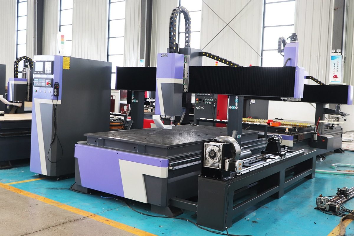
What Are 3D CNC Routers?
3D CNC routers are computer-controlled machining systems designed to create complex three-dimensional shapes, contours, reliefs, and detailed surface features from digital models. Unlike conventional CNC routing, which primarily focuses on flat cutting, drilling, and engraving, 3D CNC routing coordinates movement across the X, Y, and Z axes to remove material at different depths. This enables the machine to produce curved surfaces, recessed patterns, sculptures, molds, prototypes, architectural decorations, and other components with varying heights and geometries.
The machining process usually begins with a 3D model created in computer-aided design software. Computer-aided manufacturing software then converts the model into toolpaths and machine-readable instructions. During operation, the router spindle rotates a cutting tool at high speed while the machine moves it precisely along the programmed path. Depending on the design, the process may include roughing to remove large amounts of material, semi-finishing to refine the general form, and finishing to achieve accurate details and smoother surfaces.
Most standard 3D CNC routers are three-axis machines, although four-axis and five-axis systems are available for more complex applications. Additional rotary or tilting axes allow the cutting tool to reach multiple sides of a workpiece, machine undercuts, and process irregular components with fewer manual repositioning steps.
3D CNC routers are widely used in woodworking, furniture manufacturing, advertising, mold and pattern making, model production, interior decoration, musical instrument manufacturing, foam processing, and composite fabrication. They can process materials such as wood, MDF, acrylic, plastics, foam, tooling board, and certain composite materials.
By combining automation, repeatability, and digital design flexibility, 3D CNC routers make it possible to manufacture intricate parts more efficiently than many manual methods. Understanding their operating principles, configurations, applications, and selection criteria can help manufacturers choose the right equipment for their production requirements.
Table of Contents
What Are 3D CNC Routers?
3D CNC routers are computer-controlled machining systems used to create three-dimensional shapes, contoured surfaces, relief carvings, molds, prototypes, decorative components, and other objects with varying depths and heights. They operate by moving a rotating cutting tool along programmed paths to remove material from a workpiece. Unlike basic cutting or engraving processes that primarily follow flat two-dimensional outlines, 3D CNC routing allows the cutting tool to move vertically as well as horizontally, producing curved, sloped, recessed, and raised surfaces.
The production process normally begins with a digital three-dimensional model. Computer-aided manufacturing software analyzes the model and generates toolpaths that determine where the cutting tool will move, how deeply it will cut, how fast it will travel, and how much material it will remove. These toolpaths are converted into machine-readable instructions, usually G-code, and sent to the CNC router.
During machining, the CNC router may complete several stages. A roughing operation removes large amounts of unnecessary material and establishes the general shape. A semi-finishing operation improves the contours and prepares the surface for final machining. A finishing operation uses a smaller or more specialized cutting tool to reproduce fine details and achieve a smoother surface.
Although most standard 3D CNC routers move along three linear axes, more advanced machines may include rotary or tilting axes. These additional movements allow the CNC router to process multiple sides of a workpiece and manufacture more complex geometries with fewer manual adjustments.
Basic Definition
3D CNC routers are a subtractive manufacturing machine that uses computer-controlled cutting tools to shape a solid workpiece according to a digital design. The term “subtractive” means that the machine produces the desired object by removing material from a larger block, sheet, or blank.
The machine typically consists of a rigid frame, worktable, gantry, spindle, cutting tool, drive system, motion-control components, CNC controller, and operating software. The workpiece is secured to the table using mechanical clamps, vacuum hold-down systems, fixtures, or other workholding devices. The spindle rotates the cutting tool at high speed, while motors move the cutting head or worktable along the programmed axes.
The X-axis generally represents movement from left to right, the Y-axis represents movement from front to back, and the Z-axis controls vertical movement. By coordinating these three axes, the CNC router can machine surfaces at different depths instead of cutting only through a flat sheet.
Different cutting tools are selected according to the required geometry and surface finish. Flat-end mills are commonly used for roughing and flat-bottomed areas, while ball-nose tools are widely used for curved surfaces, relief carving, and detailed finishing. Tapered ball-nose tools may be used for deep carvings and fine details because their shape combines a narrow cutting tip with greater overall tool rigidity.
3D CNC routers are commonly used to process wood, MDF, plywood, acrylic, plastics, foam, tooling board, solid-surface materials, and certain composites. Their suitability for a particular material depends on spindle power, machine rigidity, cutting-tool selection, dust collection, cooling requirements, and the manufacturer’s recommended operating range.
Meaning of “3D” in CNC Routing
The word “3D” in CNC routing refers to the machine’s ability to create geometry with variations in width, length, and depth. A two-dimensional design contains only X and Y coordinates, while a three-dimensional design also includes Z-axis information. This additional dimension allows the router to create changes in height across the surface of the workpiece.
For example, a 2D routing operation may cut the outline of a letter from a sheet. A 2.5D operation may engrave pockets, drill holes, or create stepped depths, but each machining area generally remains flat. A true 3D routing operation continuously changes the Z-axis position while the tool moves across the X and Y axes. This coordinated motion produces flowing contours, rounded forms, sculpted surfaces, and other non-flat geometries.
The designation “3D CNC router” does not necessarily mean that the machine can reach every side of a workpiece during a single setup. A conventional three-axis router normally machines the top surface and any areas that can be reached directly from above. Processing the sides or underside may require the operator to reposition the workpiece.
A four-axis CNC router adds a rotary axis, allowing the workpiece to rotate while it is being machined. This configuration is useful for columns, furniture legs, statues, balusters, and cylindrical components. A five-axis router adds further rotational or tilting movement, enabling the cutting tool to approach the workpiece from multiple directions. This makes it suitable for complex components, deep cavities, undercuts, irregular surfaces, and multi-sided machining.
Therefore, “3D” primarily describes the geometry being produced rather than the total number of machine axes. A standard three-axis machine can perform extensive 3D surface machining, while four-axis and five-axis systems expand tool accessibility and reduce the need for manual repositioning.
CNC Router Versus Manual Router
Manual routers are a handheld or table-mounted power tool controlled directly by an operator. The operator guides the tool along the workpiece, adjusts the cutting depth, and relies on templates, fences, bearings, jigs, or personal skill to maintain the desired path. Manual routers are flexible, affordable, and useful for edge profiling, trimming, simple grooves, decorative work, and small custom projects.
CNC routers perform similar cutting actions, but their movement is controlled by a computer program. Instead of manually guiding the cutting tool, the operator creates or imports a digital design, generates the machining instructions, secures the material, installs the correct tool, sets the machine coordinates, and starts the program.
The main advantage of CNC routers is repeatability. Once a machining program has been tested, the machine can reproduce the same shape many times with minimal variation. This is especially valuable for batch production, matched components, detailed carvings, and products that must meet consistent dimensional requirements.
CNC routers can also execute complex toolpaths that would be difficult or extremely time-consuming to reproduce by hand. Smooth three-dimensional contours, intricate reliefs, nested components, repeated patterns, and precise pockets can be produced automatically from digital files.
However, CNC routers require more preparation than manual routers. The operator must understand digital design, toolpath programming, workholding, cutting parameters, coordinate systems, tool selection, and machine safety. Setup errors can damage the workpiece, cutting tool, or machine. Manual routers may therefore remain more practical for quick modifications, simple one-off operations, installation work, and tasks that do not justify CNC programming.
The two tools are not always direct replacements for one another. Many workshops use CNC routers for accuracy, complex machining, and repeated production, while retaining manual routers for finishing, adjustments, and flexible on-site work.
CNC Router Versus CNC Milling Machine
CNC routers and CNC milling machines are both subtractive manufacturing systems. They use rotating cutting tools and computer-generated toolpaths to remove material. However, they are generally designed for different materials, cutting forces, operating speeds, and production requirements.
CNC routers commonly have larger work areas and higher spindle speeds. They are designed to move rapidly across relatively large sheets, panels, blocks, and lightweight workpieces. They are widely used for woodworking, plastics, foam, composites, signage, furniture parts, decorative panels, molds, and prototypes.
CNC milling machines are generally built with heavier frames, more rigid structures, and motion systems capable of resisting higher cutting forces. They are often designed for high-precision machining of dense engineering materials and compact components. Their work areas may be smaller than those of large-format CNC routers, but they usually provide greater rigidity and dimensional control under demanding cutting conditions.
The spindle characteristics also differ. CNC routers typically operate at high rotational speeds that suit smaller cutting tools and materials requiring fast, clean cuts. CNC milling machines may provide greater torque at lower speeds, which is useful when taking deeper cuts or machining materials that generate greater resistance.
Workholding practices can also vary. CNC routers frequently use vacuum tables to secure sheets and panels, although clamps and custom fixtures are also common. CNC milling machines more often use precision vises, T-slot fixtures, chucks, and dedicated workholding systems designed to withstand substantial machining forces.
CNC routers are usually the more efficient choice for large-format parts, sheet processing, woodworking, relief carving, and high-speed contouring. CNC milling machines are generally more appropriate when very high rigidity, tight tolerances, heavy material removal, or demanding precision is required.
The distinction is not absolute. Heavy-duty CNC routers can perform some operations commonly associated with CNC milling machines, while certain CNC milling machines can process materials normally used on CNC routers. The correct choice depends on the workpiece size, material, required accuracy, production volume, surface-finish expectations, cutting forces, and available tooling.
CNC Router Versus 3D Printer
CNC routers and 3D printers can both manufacture physical objects from digital models, but they use fundamentally different production methods. CNC routers are a subtractive machine, whereas 3D printers generally use an additive process.
CNC routers begin with a solid piece of material and remove unwanted portions until the desired shape remains. 3D printers build an object by depositing, curing, sintering, or bonding material layer by layer. As a result, the CNC router creates chips, dust, or offcuts, while the printer gradually adds only the material required to form the part, along with any necessary support structures.
CNC routing can produce components from commercially available boards, sheets, blocks, and blanks. The finished part retains many of the original material’s properties because it is cut from a solid workpiece. This can provide good strength, stiffness, appearance, and surface quality, depending on the material and machining process.
Three-dimensional printing offers greater freedom for producing enclosed internal channels, hollow structures, lattice patterns, and complex geometries that may be difficult or impossible to reach with a cutting tool. However, printed parts may show visible layer lines, require support removal, or need sanding and other finishing operations.
CNC routers can often manufacture large, relatively simple parts faster than 3D printers, particularly when machining foam, wood, plastics, or tooling board. They are well suited to molds, patterns, panels, signs, furniture components, and large prototypes. 3D printers may be more suitable for small prototypes, complex internal structures, customized parts, and designs that would require excessive material removal on CNC routers.
Material waste is another important difference. CNC routing removes material and may generate substantial waste, although efficient nesting and reusable offcuts can reduce it. Additive manufacturing can use material more selectively, but failed prints, support structures, and test parts can also create waste.
In some production environments, CNC routers and 3D printers are complementary rather than competing technologies. 3D printers may be used to produce a complex prototype, while CNC routers may machine a mold, fixture, base, enclosure, or final component. The preferred method depends on part geometry, size, material properties, accuracy, surface finish, production time, and cost.
3D CNC routers are automated subtractive manufacturing machines that transform digital models into physical parts by removing material with a rotating cutting tool. Their coordinated X-, Y-, and Z-axis movements allow them to create curved surfaces, relief carvings, recessed features, molds, patterns, prototypes, and other geometries with continuously changing depths.
The term “3D” describes the machine’s ability to reproduce three-dimensional surface information rather than simply cut flat outlines. Standard 3-axis CNC routers can perform extensive 3D machining from above, while 4-axis and 5-axis configurations provide greater access to the sides and complex areas of a workpiece.
Compared with manual routers, CNC routers provide greater automation, consistency, repeatability, and the ability to execute intricate digital toolpaths. Compared with CNC milling machines, they generally offer larger work areas and faster movement for lightweight materials, while CNC milling machines typically provide greater rigidity for high-force, high-precision machining. Compared with 3D printers, CNC routers remove material from solid blanks instead of building objects layer by layer.
Understanding these distinctions helps manufacturers determine whether 3D CNC routers are appropriate for their applications. The final decision should consider the material, component dimensions, geometric complexity, required accuracy, desired surface quality, production volume, and available budget.
How Do 3D CNC Routers Work?
3D CNC routers work by converting a digital three-dimensional design into a sequence of controlled cutting movements. The machine uses a rapidly rotating cutting tool to remove material from a solid workpiece until the programmed shape is produced. During machining, the cutting tool moves along the X, Y, and Z axes, allowing it to create flat areas, curved surfaces, slopes, recessed details, raised reliefs, and continuously changing depths.
The complete workflow usually includes digital design creation, toolpath programming, G-code generation, material setup, cutting-tool installation, automated machining, and final inspection. Each stage directly affects the dimensional accuracy, surface quality, machining time, and safety of the process.
Most complex 3D projects are completed through several machining operations rather than a single cutting pass. Roughing removes large amounts of excess material and forms the general shape. Semi-finishing refines the contours and leaves a smaller, more consistent amount of material for the final operation. Finishing uses smaller stepovers, shallower cuts, and specialized tools to produce fine details and smoother surfaces.
Although the CNC router performs the physical cutting automatically, successful production still depends on careful preparation. The operator must select appropriate software, cutting tools, spindle speeds, feed rates, cutting depths, workholding methods, and toolpath strategies. Incorrect settings can cause poor surface quality, broken tools, dimensional errors, material movement, or collisions.
Digital Design Creation
The process begins with a digital design that represents the final shape of the part. This design is normally created using computer-aided design software, commonly known as CAD software. Depending on the application, the designer may create a solid model, surface model, mesh model, relief pattern, or a combination of two-dimensional and three-dimensional geometry.
Simple projects may begin with two-dimensional vectors that are later assigned different cutting depths. More complex applications, such as sculptures, molds, patterns, architectural decorations, furniture components, and prototypes, usually require a complete three-dimensional model.
The digital model defines the size, shape, contours, pockets, holes, slopes, and surface details of the finished part. However, the CNC router does not directly interpret the visual model in the same way a person does. The model must first be processed by computer-aided manufacturing software so that its geometry can be translated into actual cutting movements.
Before toolpath programming begins, the model should be checked carefully. Common problems include open surfaces, overlapping vectors, incorrect dimensions, reversed surface directions, unnecessary geometry, and features that are too small for the available cutting tools. The designer must also confirm that the model is suitable for subtractive machining. Deep narrow cavities, inaccessible undercuts, and enclosed internal features may not be reachable with standard 3-axis CNC routers.
The position and orientation of the model must also be determined. The designer may need to rotate the part, divide it into several sections, or add reference surfaces and alignment features. For multi-sided machining, locating holes, pins, fixtures, or indexed rotary positions may be incorporated into the design to ensure accurate repositioning.
Toolpath Generation
After the digital model is completed, it is imported into computer-aided manufacturing software, commonly called CAM software. The CAM system generates toolpaths that specify how the cutting tool will travel over and through the workpiece.
Toolpath generation is one of the most important stages because the same digital model can be machined in many different ways. The selected strategy affects production speed, tool life, surface finish, material waste, and overall accuracy.
A typical 3D routing project begins with a roughing toolpath. Roughing removes most of the unnecessary material using a relatively large, strong cutting tool. The tool normally moves in layers, removing a controlled depth during each pass. The roughing operation does not reproduce every fine detail. Instead, it leaves a predetermined amount of material, known as stock allowance, for later finishing operations.
A semi-finishing toolpath may be added between roughing and finishing. Semi-finishing creates a more uniform surface and removes the large steps left by the roughing tool. This helps maintain a consistent cutting load during the final operation and can improve the accuracy and surface quality of the finished part.
The finishing toolpath follows the three-dimensional contours more closely. Ball-nose or tapered ball-nose tools are often used because their rounded tips can move smoothly across curved surfaces. Finishing may follow parallel lines, contours, spirals, radial paths, waterline levels, or a combination of strategies.
During toolpath creation, the programmer sets the spindle speed, feed rate, plunge rate, cutting depth, stepover, tool orientation, machining direction, entry method, and clearance height. The CAM software may also calculate the remaining material and generate additional rest-machining toolpaths for areas that larger tools could not reach.
A simulation should be performed before machining. The simulation shows how material will be removed and helps identify collisions, uncut areas, excessive tool engagement, incorrect cutting depths, and unnecessary movements. Although simulation cannot eliminate every risk, it is an essential step for verifying complex 3D operations.
G-Code Creation
Once the toolpaths have been programmed and verified, the CAM software converts them into G-code. G-code is the machine-readable language that instructs the CNC router how to move and operate.
The program contains commands that control the position of each axis, spindle start and stop, spindle speed, feed rate, tool changes, coolant or dust-collection functions, and other machine actions. For example, one command may tell the CNC router to move rapidly to a safe position, while another may instruct it to cut along a specific path at a controlled feed rate.
The CAM software uses a post-processor to create G-code that matches the controller and mechanical configuration of the CNC router. Different CNC control systems may interpret commands differently, so the correct post-processor must be selected. A program generated for one controller should not automatically be assumed to work correctly on another machine.
Before transferring the program to the CNC router, the operator should review important information such as the selected coordinate system, unit system, tool numbers, spindle settings, safe heights, and program origin. Errors involving millimeters and inches, positive and negative Z-axis directions, or incorrect work origins can cause serious machining problems.
The finished G-code file is then transferred to the CNC controller through a network connection, USB device, direct computer connection, or other supported method. Many modern controllers also provide a graphical toolpath preview, allowing the operator to verify the program before starting the machine.
Workpiece Setup
The workpiece must be positioned and secured correctly before machining begins. Even a perfectly designed program cannot produce accurate results if the material moves, vibrates, bends, or is incorrectly aligned during cutting.
Common workholding methods include mechanical clamps, vacuum tables, screws, double-sided adhesive, dedicated fixtures, vises, and locating pins. The appropriate method depends on the material, workpiece size, cutting forces, available machine equipment, and whether the toolpath cuts completely through the material.
Large sheets are commonly held with a vacuum table. The vacuum system pulls the material against the work surface and can reduce setup time. However, vacuum holding force may be insufficient for small parts, warped boards, porous materials, or workpieces with limited surface area. In these cases, mechanical clamps, tabs, screws, or custom fixtures may be necessary.
The operator must make sure that clamps and fixtures do not interfere with the cutting tool, spindle, collet, dust shoe, or gantry. CAM software may be used to model the fixtures and detect potential collisions.
After securing the material, the work coordinate system must be established. This process tells the controller where the programmed origin is located on the actual workpiece. The origin may be set at a corner, the center of the material, the top surface, the machine bed, or a reference point built into a fixture.
The X- and Y-axis positions may be set manually or with an edge finder, locating system, camera, or probe. The Z-axis position is commonly established using a touch-off plate, tool-length sensor, or manual paper method. Accurate zero setting is especially important in 3D routing because even a small Z-axis error can change the depth, thickness, and surface geometry of the finished part.
For two-sided or multi-sided machining, the setup must include an accurate method of repositioning the workpiece. Dowel pins, fixture stops, rotary axes, indexed tables, and probing systems can help maintain alignment between machining operations.
Tool Selection and Installation
The cutting tool must be selected according to the material, machining stage, part geometry, and required surface finish. Using the wrong tool can increase machining time, damage the material, reduce accuracy, or prevent the CNC router from reaching important features.
Large flat-end tools are commonly used for roughing because they can remove material efficiently and produce relatively flat step levels. End mills may also be used for pockets, flat surfaces, slots, and perimeter cutting.
Ball-nose tools are widely used for 3D finishing. Their rounded cutting ends allow them to follow curved surfaces without leaving sharp rectangular steps. However, the effective cutting speed near the center of a ball-nose tool is relatively low, so feed rates, spindle speeds, tool angles, and stepovers must be selected carefully.
Tapered ball-nose tools are often used for detailed reliefs, deep carvings, and narrow features. Their tapered bodies provide greater rigidity than straight tools with the same small tip diameter. Engraving tools, compression bits, down-cut tools, up-cut tools, and specialized composite or plastic-cutting tools may also be selected for particular applications.
The tool diameter affects both efficiency and detail. A large tool removes material quickly but cannot enter small corners or reproduce fine features. A small tool can create greater detail but is usually more fragile and requires longer machining times. Complex jobs frequently use several tools, beginning with a large roughing tool and ending with one or more smaller finishing tools.
Before installation, the tool should be inspected for wear, damage, contamination, or chipped cutting edges. The collet, tool holder, and spindle taper should also be clean. Dust or debris between these components can cause tool runout, vibration, poor surface quality, and uneven cutting.
The tool must be inserted to a safe depth and tightened according to the manufacturer’s specifications. Excessive tool extension should be avoided because it reduces rigidity and increases vibration. However, the tool must extend far enough to reach the required machining depth without allowing the collet or tool holder to contact the workpiece.
After installation, the tool length must be measured or entered into the controller. Machines equipped with automatic tool changers may store individual tool-length offsets so that different tools can be used within the same program.
Automated Material Removal
Once the digital program, workpiece, tools, and coordinate system have been verified, the automated cutting process can begin. Before full machining, the operator may perform a dry run, single-block test, or reduced-speed trial to confirm that the machine follows the expected path without collisions.
During operation, the spindle rotates the cutting tool while the control system coordinates movement along the machine axes. Motors drive the gantry, spindle, or worktable according to the G-code instructions. The controller continuously calculates the required positions so that the cutting tool follows the programmed geometry.
In a 3-axis CNC router, the X-, Y-, and Z-axis movements may occur simultaneously. This coordinated movement allows the tool to follow slopes and curved surfaces. In a four-axis system, the controller may also rotate the workpiece. 5-axis CNC routers can change the position or angle of the cutting tool relative to the surface, providing greater access to complex geometries.
The first stage is often roughing. The machine removes material in layers while maintaining the programmed depth of cut and stock allowance. Roughing toolpaths are designed to remove material efficiently while avoiding excessive cutting forces.
After roughing, the CNC router may perform semi-finishing and finishing operations. During finishing, the cutting tool follows the surface with a smaller stepover. The stepover is the distance between adjacent tool passes. A smaller stepover usually creates a smoother surface because the ridges between passes are reduced. However, reducing the stepover also increases machining time.
The cutting direction can influence surface quality. Conventional cutting and climb cutting create different relationships between tool rotation and feed direction. The best choice depends on the material, tool geometry, machine rigidity, and finishing requirements.
Throughout the process, chips and dust must be removed effectively. Dust-collection systems are commonly used when processing wood, MDF, foam, plastics, and composites. Inadequate extraction can reduce visibility, increase fire or health risks, cause tool heating, and allow debris to interfere with the cutting process.
The operator should continue monitoring the machine even though the movements are automated. Warning signs include unusual vibration, changing spindle sounds, excessive dust, burning, melting, tool chatter, material movement, abnormal surface marks, or visible tool damage. Emergency-stop controls should remain accessible at all times.
Finishing and Inspection
After the machining program is completed, the workpiece is removed carefully from the table or fixture. Tabs, holding bridges, or excess stock may need to be cut away. The finished part may also require sanding, polishing, deburring, cleaning, sealing, painting, or coating.
The amount of manual finishing depends heavily on the toolpath strategy and selected stepover. Three-dimensional CNC routing often leaves small ridges known as scallops or cusps between adjacent tool passes. A smaller stepover reduces these ridges but increases machining time. The manufacturer must balance machine time against the cost of manual finishing.
Some materials require special post-processing. Wood parts may need sanding and sealing. Acrylic may require edge polishing. Foam patterns may need coating or reinforcement. Composite parts may require careful dust removal and edge treatment. Mold surfaces may need progressively finer machining and polishing to achieve the required finish.
Dimensional inspection should be performed after machining. Basic measurements may be taken with calipers, rulers, height gauges, templates, or micrometers. More complex components may be inspected with coordinate measuring machines, laser scanners, optical systems, or three-dimensional comparison software.
The inspection process should verify overall dimensions, feature locations, depths, surface geometry, alignment, and visible defects. For molds and matched components, the operator may also test how parts fit together.
If errors are found, their causes should be identified before the next production run. Dimensional deviations may result from incorrect tool diameter, tool wear, material movement, inaccurate zero setting, machine backlash, spindle runout, thermal expansion, or an incorrect digital model. Poor surface quality may result from excessive stepover, unsuitable tool geometry, incorrect feed rates, vibration, dull tools, or inconsistent material properties.
Inspection results can be used to adjust tool offsets, work coordinates, toolpaths, or cutting parameters. This feedback process helps improve repeatability and ensures that future parts meet the required quality standards.
3D CNC routers operate through a carefully connected digital and physical workflow. The process begins with the creation of a three-dimensional CAD model. CAM software then converts the model into roughing, semi-finishing, and finishing toolpaths. A suitable post-processor translates these toolpaths into G-code that the CNC controller can understand.
Before machining begins, the workpiece must be positioned securely, the work coordinate system must be established, and the correct cutting tools must be installed. The CNC router then follows the programmed instructions automatically, coordinating movement across three or more axes while the rotating tool removes material.
Roughing operations form the general shape efficiently, while finishing operations reproduce detailed contours and improve surface quality. Tool diameter, cutting geometry, spindle speed, feed rate, cutting depth, stepover, workholding, and dust extraction all influence the final result.
Once machining is complete, the part may require sanding, polishing, deburring, cleaning, or coating. It should also be inspected for dimensional accuracy, correct geometry, surface quality, and visible defects.
Although 3D CNC routers automate the cutting process, the quality of the finished component depends on every stage that comes before and after machining. Accurate design, reliable toolpath programming, correct setup, appropriate tool selection, continuous monitoring, and systematic inspection are all necessary for safe, efficient, and repeatable production.
Types of 3D CNC Routers
3D CNC routers can be classified according to the number and arrangement of their controlled motion axes. The machine configuration determines how the cutting tool approaches the workpiece, which surfaces can be reached, how often the material must be repositioned, and what types of three-dimensional geometry can be produced.
The main configurations include 3-axis, 4-axis, and 5-axis CNC routers. Rotary-axis CNC routers form another important category and are specifically designed to machine cylindrical, round, tapered, or elongated workpieces. Although both 4-axis and rotary-axis CNC routers include rotational movement, they do not necessarily use it in the same way.
Increasing the number of controlled axes can improve tool accessibility and reduce the need to reposition the workpiece. However, more axes also increase machine cost, programming complexity, calibration requirements, and collision risks. A machine with more axes is therefore not automatically the best choice for every application.
3-axis CNC routers are usually sufficient for relief carvings, molds, decorative panels, signs, furniture components, and other parts that can be machined from above. 4-axis CNC routers provide an additional cutting-tool rotation that helps process side surfaces and angled features. 5-axis CNC routers offer even greater freedom by controlling two rotational axes. Rotary-axis machines are most suitable for full-circumference machining of round or cylindrical parts.
3-Axis CNC Routers
3-axis CNC routers are the most common configuration for general routing and three-dimensional surface machining. It controls movement along three linear axes: X, Y, and Z. The X-axis typically represents left-to-right movement, the Y-axis controls front-to-back movement, and the Z-axis raises or lowers the cutting tool.
By coordinating these three axes, the CNC router can cut profiles, drill holes, machine pockets, engrave patterns, and create surfaces with continuously changing depths. During a 3D machining operation, the X-, Y-, and Z-axis positions can change simultaneously, allowing a ball-nose or tapered ball-nose tool to follow curved and contoured surfaces.
The spindle of a conventional 3-axis CNC router remains in a fixed vertical orientation. The cutting tool normally approaches the workpiece from above, making this configuration suitable for parts whose important features can be reached with a vertically positioned tool.
Common applications include relief carvings, decorative panels, cabinet doors, signs, molds, patterns, furniture components, musical instrument parts, foam models, prototypes, and packaging forms. The machine can also perform conventional 2D and 2.5D operations, including profile cutting, slotting, drilling, pocketing, and engraving.
One of the greatest advantages of 3-axis CNC routers is their relatively simple mechanical structure. It is generally easier to program, operate, maintain, and troubleshoot than CNC routers with additional rotational axes. Three-axis CAM software is widely available, and operators can learn its programming workflow without immediately mastering complex multi-axis machining strategies.
Many 3-axis CNC routers also provide large work areas suitable for full-size sheets, panels, blocks, and multiple nested parts. They can be equipped with automatic tool changers, vacuum tables, tool-length sensors, dust-collection systems, and automatic loading and unloading equipment.
However, 3-axis CNC routers have limitations regarding tool accessibility. They cannot normally machine the sides or underside of a workpiece during a single setup. Deep cavities, undercuts, vertical side features, and complex multi-sided components may require manual repositioning of the material.
Each repositioning operation increases setup time and can introduce alignment errors. Locating pins, custom fixtures, reference holes, and probing systems may be required to maintain accuracy between setups. Nevertheless, for many woodworking, advertising, mold-making, and general manufacturing applications, 3-axis CNC routers provide the best balance of capability, simplicity, and cost.
4-Axis CNC Routers
4-axis CNC routers add one rotational axis to the three standard linear axes. The machine therefore controls movement along the X, Y, and Z axes while also rotating or tilting the cutting tool. This additional movement changes the angle at which the tool approaches the workpiece.
The rotational axis may be identified as the A-axis or B-axis, depending on the direction of rotation and the machine manufacturer’s coordinate convention. For example, rotation around the X-axis is normally called A-axis movement, while rotation around the Y-axis is generally called B-axis movement.
Unlike standard 3-axis CNC routers, whose spindle remains vertical, 4-axis CNC routers can angle the cutting tool toward the sides of a workpiece. This allows it to machine sidewalls, beveled edges, angled holes, inclined surfaces, and other features that cannot be reached effectively with a fixed vertical spindle.
Four-axis machining may be indexed or simultaneous. During indexed 4-axis machining, the rotational axis moves the cutting tool to a specified angle and then holds that position while the X, Y, and Z axes perform the machining operation. After one surface is completed, the tool rotates to another angle for the next operation.
During simultaneous 4-axis machining, the rotational axis can move continuously while the linear axes are also moving. This coordinated movement enables the tool to follow more complex contours and maintain a suitable angle relative to the changing surface of the workpiece.
A major advantage of 4-axis CNC routers is that they can process multiple surfaces without requiring the operator to remove and reposition the material as frequently. Reducing manual setups can shorten production time, improve alignment between features, and lower the risk of positioning errors.
4-axis CNC routers are useful for machining curved architectural components, furniture parts, molds, patterns, sculptures, composite components, decorative structures, and workpieces containing angled or vertical side features. They can also be used for trimming formed parts whose edges are not located on a single horizontal plane.
Because the cutting tool can approach the surface from an angle, the machine may be able to use shorter tools for some deep or difficult-to-reach areas. Shorter tools are normally more rigid and less likely to vibrate, which can improve machining stability and surface quality.
However, a single rotational axis does not provide the same directional freedom as a 5-axis system. The cutting tool can rotate around only one defined axis, so some surfaces, undercuts, and complex orientations may remain inaccessible. The workpiece may still require repositioning if important features are located outside the available range of movement.
Programming 4-axis CNC routers is also more complicated than programming 3-axis CNC routers. The CAM software must support the machine’s rotational configuration, and the operator must define the tool orientation, rotational limits, safe movements, and collision-clearance requirements accurately.
Collision risks increase because the spindle body, tool holder, cutting tool, gantry, fixtures, and workpiece may be positioned at different angles relative to one another. Toolpath simulation and careful verification are therefore essential before machining begins.
4-axis CNC routers are suitable for manufacturers that need to machine angled surfaces or several sides of a part but do not require the complete directional flexibility or higher investment associated with 5-axis CNC routers.
5-Axis CNC Routers
5-axis CNC routers control movement along three linear axes and two rotational axes. These additional rotational movements allow the cutting tool to approach the workpiece from a much wider range of directions and angles.
Depending on the machine design, the spindle head may tilt and rotate, the worktable may move on two rotary axes, or the machine may combine a tilting spindle with a rotating table. The rotational movements are commonly identified as A, B, or C axes according to the linear axes around which they rotate.
A major advantage of 5-axis routing is improved tool accessibility. The cutting tool can reach sidewalls, angled surfaces, deep cavities, and irregular features that would be difficult or impossible to process with a fixed vertical spindle. This capability allows many complex parts to be completed in a single setup.
Reducing the number of setups improves the positional relationship between features because the workpiece does not need to be removed and realigned repeatedly. It can also reduce fixture requirements, shorten production time, and minimize errors caused by manual repositioning.
5-axis CNC routing can be divided into indexed and simultaneous machining. In indexed machining, often described as 3+2 machining, the two rotational axes position the tool or workpiece at a selected angle. These axes then remain stationary while the X, Y, and Z axes perform the cutting operation.
Indexed machining is useful for processing several angled surfaces without requiring continuous 5-axis movement. It is generally easier to program and verify than fully simultaneous machining while still providing much greater accessibility than standard 3-axis CNC routers.
During simultaneous 5-axis machining, all 5 axes can move together. The angle and position of the cutting tool change continuously as it follows the programmed surface. This allows the machine to produce smooth transitions, complex contours, deep curved surfaces, and irregular geometries while maintaining a suitable cutting orientation.
5-axis CNC routers are used for automotive models, aerospace patterns, marine components, molds, architectural structures, composite trimming, advanced woodworking, sculptures, and full-size prototypes. They are particularly useful for large or complex workpieces that must be machined from several directions.
Another advantage is the ability to use shorter cutting tools. Because the spindle can tilt toward difficult areas, the tool does not need to extend as far from the holder. Shorter tools are generally more rigid, produce less vibration, and may provide better accuracy and surface quality.
However, 5-axis CNC routers are significantly more complex than 3-axis and 4-axis CNC routers. They require advanced CAM software, accurate calibration, reliable toolpath simulation, careful fixture design, and experienced operators.
The potential for collisions is also greater. The spindle head, tool holder, cutting tool, fixtures, workpiece, rotary components, and machine frame may all move relative to one another. Even a small programming or setup error can result in a serious collision.
5-axis systems also require a larger initial investment and more demanding maintenance. Their additional motors, drives, bearings, sensors, and mechanical components increase both purchase costs and long-term service requirements.
For simple panels, flat components, relief carvings, and top-surface machining, 5-axis CNC routers may offer little practical advantage over correctly selected 3-axis CNC routers. It is most valuable when multi-directional tool access directly reduces setups, enables otherwise inaccessible geometry, or improves the production of complex components.
Rotary-Axis CNC Routers
Rotary-axis CNC routers are designed to machine a workpiece while the workpiece rotates around a central axis. Instead of tilting or rotating the cutting tool, the rotary device turns the material so that different areas of its circumference can be presented to the spindle.
The workpiece is normally secured between a powered chuck and a tailstock. The chuck grips and rotates the material, while the tailstock supports the opposite end and helps maintain alignment. Faceplates, specialized fixtures, and intermediate supports may also be used for parts with unusual dimensions or shapes.
Rotary-axis CNC routers are commonly used to produce cylindrical, round, tapered, twisted, and ornamental components. Typical products include table legs, chair legs, stair balusters, columns, decorative posts, statues, handrails, spindles, wooden handles, foam sculptures, and architectural ornaments.
A basic rotary machine may index the workpiece to several fixed positions. At each position, the CNC router performs conventional linear-axis machining on the exposed surface. After one side is completed, the workpiece rotates to another programmed angle.
More advanced systems allow simultaneous movement of the rotary axis and one or more linear axes. This coordinated motion can produce spiral grooves, helical patterns, flutes, twisted forms, carved figures, and fully sculpted surfaces around the complete circumference of the material.
Rotary CNC routing differs from conventional lathe turning. On a lathe, the workpiece normally rotates continuously while a stationary cutting tool removes material, making the process highly efficient for symmetrical round profiles. Rotary-axis CNC routers use a rotating spindle tool and can produce asymmetrical carvings, lettering, pockets, recesses, and detailed surface patterns.
Some CNC routers use a removable rotary attachment mounted on the standard worktable. This arrangement allows the same machine to alternate between flat-sheet processing and cylindrical machining. However, the maximum workpiece diameter may be limited by the distance between the rotary centerline, gantry, spindle, and table.
Other machines use a recessed or side-mounted rotary unit. Placing the rotary axis below or beside the normal table surface creates additional clearance for larger-diameter workpieces. Dedicated rotary-axis CNC routers may be designed entirely for cylindrical production and may not include a conventional flat worktable.
Accurate alignment is essential. The centerline of the workpiece must correspond with the rotational center defined in the CNC program. Incorrect alignment can cause uneven cutting depths, distorted geometry, mismatched details, or visible seams where toolpaths meet.
Workholding must also be strong enough to prevent the material from slipping or vibrating. Long, narrow workpieces may bend under cutting pressure, particularly near their center. Tailstocks, steady rests, intermediate supports, lighter cutting depths, and controlled feed rates may be necessary.
Rotary-axis CNC routers offer a practical solution for workshops that regularly manufacture round or cylindrical products. They can provide full-circumference machining at a lower cost and with less programming complexity than full 5-axis CNC routers.
The main types of 3D CNC routers are distinguished by the number and arrangement of their linear and rotational axes. Each configuration provides a different balance of machining accessibility, programming complexity, production efficiency, and investment cost.
3-axis CNC routers move along the X, Y, and Z axes and normally use a fixed vertical spindle. It is suitable for relief carving, molds, signs, panels, furniture components, prototypes, and other parts that can be machined primarily from above.
4-axis CNC routers add one rotational axis that rotates or tilts the cutting tool. This enables the tool to approach sidewalls, angled surfaces, beveled edges, and other features that cannot be reached effectively with a fixed vertical spindle.
5-axis CNC routers add two rotational axes, allowing the cutting tool to approach the workpiece from multiple directions. It is suitable for complex surfaces, deep cavities, angled features, and multi-sided parts that would otherwise require numerous setups.
Rotary-axis CNC routers rotate the workpiece around a central axis while the spindle removes material. It is specifically suited to cylindrical, tapered, twisted, and ornamental components such as furniture legs, balusters, columns, statues, and decorative posts.
Choosing the right CNC router requires more than selecting the machine with the greatest number of axes. Manufacturers should evaluate the geometry of their products, required tool access, workpiece dimensions, material, production volume, accuracy expectations, programming capabilities, available space, and budget. The best machine is the one that produces the required components reliably without introducing unnecessary mechanical or operational complexity.
Main Components of 3D CNC Routers
3D CNC routers are made up of mechanical, electrical, motion-control, workholding, and auxiliary systems that work together to convert digital toolpaths into precise cutting movements. Each component has a specific function, but the machine’s overall performance depends on how effectively these components are designed, integrated, calibrated, and maintained.
The machine frame and gantry provide structural support and resist the forces generated during cutting. The spindle supplies the rotational power needed to drive the cutting tool, while the tool holder and collet secure the tool accurately. Linear guides, drive mechanisms, and motors move the spindle or gantry along the programmed axes. The CNC controller coordinates these movements according to the G-code created by CAM software.
Supporting components also have an important influence on production quality. A vacuum table holds sheet materials securely, while a dust-collection system removes chips and airborne particles. Tool sensors and probing systems simplify setup and improve positioning accuracy. The lubrication system protects guide rails, bearings, ball screws, racks, and other moving parts from premature wear.
The quality of these components affects machining speed, repeatability, dimensional accuracy, surface finish, reliability, and service life. A powerful spindle cannot compensate for a flexible frame, just as a rigid machine cannot achieve accurate results if its drive system has excessive backlash. Understanding the main components of 3D CNC routers helps users evaluate machine quality, select an appropriate configuration, and maintain the equipment correctly.
Machine Frame
The machine frame forms the structural foundation of 3D CNC routers. It supports the worktable, gantry, linear guides, drive system, spindle assembly, and other major components. Its primary purpose is to maintain geometric stability while resisting cutting forces, acceleration, vibration, and the weight of moving assemblies.
Frames are commonly manufactured from welded steel, cast iron, aluminum profiles, or a combination of these materials. Welded steel frames are widely used in industrial CNC routers because they provide a good balance of strength, rigidity, size, and manufacturing cost. After welding, the frame may be stress-relieved through heat treatment or vibration-aging processes to reduce internal stresses that could cause gradual deformation.
Cast-iron structures offer excellent vibration damping and dimensional stability. They are often used in high-precision or heavy-duty machines, although their weight and manufacturing cost can be higher. Aluminum-profile frames are lighter and easier to assemble, making them suitable for smaller or entry-level CNC routers. However, they may provide less rigidity than heavy welded or cast structures.
Frame rigidity directly affects cutting quality. If the structure bends or vibrates under load, the cutting tool may deviate from its programmed path. This can cause dimensional errors, chatter marks, rough surfaces, inconsistent cutting depths, and faster tool wear. The problem becomes more significant during aggressive roughing, rapid acceleration, or machining with long cutting tools.
The frame must also provide a stable mounting surface for the linear guides and drive components. Misaligned or uneven mounting surfaces can create binding, uneven wear, and positioning errors. High-quality machines normally have their guide-rail mounting surfaces precision-machined after frame fabrication.
The weight and footprint of the frame should match the intended application. Large-format CNC routers require substantial structural support to maintain accuracy across long travel distances. Machines designed for lightweight foam or wood may not need the same mass as CNC routers used for dense composites or demanding mold production. Nevertheless, adequate rigidity remains essential for every type of 3D machining.
Gantry
The gantry is the bridge-like structure that spans the machine’s work area and supports the spindle assembly. Depending on the machine design, the gantry may move along the length of the table while the spindle moves across it, or the gantry may remain fixed while the worktable moves underneath.
Most large-format CNC routers use a moving-gantry design. This arrangement provides a large work area without requiring the entire table and workpiece to move. It is especially suitable for processing full-size panels, long components, and heavy materials.
The gantry must be strong enough to support the spindle, Z-axis assembly, motors, cable carriers, dust shoe, and optional tool-changing equipment. At the same time, it should be light enough to accelerate and decelerate efficiently. Excessive gantry weight can limit speed and place greater loads on motors and drive components, while an undersized gantry may flex during cutting.
Manufacturers use steel, cast aluminum, extruded aluminum, or reinforced welded structures to create a balance between rigidity and mass. The gantry cross-section is particularly important because its height, width, wall thickness, and internal reinforcement influence resistance to bending and twisting.
A wide or tall gantry may be required for processing thick workpieces, molds, foam blocks, rotary-axis parts, or large sculptures. However, increasing gantry clearance can reduce rigidity if the structure is not reinforced properly. A machine with a very high Z-axis travel must therefore have sufficient structural strength to maintain accuracy when the spindle is extended.
Gantry squareness is also critical. Both sides of a moving gantry must remain synchronized as they travel along the machine bed. If one side moves ahead of the other, the gantry can become skewed, causing inaccurate cuts and excessive stress on the linear guides. Industrial machines often use dual motors, dual drive systems, or electronic gantry-squaring functions to maintain alignment.
The rigidity and alignment of the gantry have a major effect on three-dimensional machining. Because 3D toolpaths involve continuous movement and frequent changes in direction, any flexing or twisting can appear as surface irregularities on the finished part.
Spindle
The spindle is the motorized assembly that rotates the cutting tool. It is one of the most important components of 3D CNC routers because its power, speed, torque, runout, cooling method, and bearing quality directly influence cutting capability and surface finish.
CNC router spindles typically operate at high rotational speeds. Depending on the machine and application, spindle speeds may range from several thousand to tens of thousands of revolutions per minute. High speeds are especially useful when machining wood, plastics, foam, composites, and other materials with relatively small-diameter tools.
Spindle power determines how effectively the machine can maintain cutting speed under load. Lower-powered spindles may be adequate for light engraving, foam machining, and small woodworking projects. Higher-powered spindles are better suited to deep cutting, large tools, demanding roughing operations, and continuous industrial production.
Torque is just as important as rated power. A spindle must provide sufficient torque at the intended operating speed. If the spindle loses speed during cutting, the tool may rub instead of cutting cleanly, causing heat, poor surface quality, tool damage, or material burning.
Spindles may be air-cooled or water-cooled. Air-cooled spindles use fans to remove heat and generally require less supporting equipment. They are relatively simple to install and maintain, although fan noise and dust exposure may be concerns. Water-cooled spindles circulate coolant through internal channels, providing effective temperature control and quieter operation. However, they require a pump, reservoir, or chiller, hoses, and regular coolant maintenance.
Bearing quality has a significant effect on spindle accuracy and service life. Precision bearings help minimize runout, which is the small rotational deviation of the cutting tool from its ideal centerline. Excessive runout can cause vibration, uneven cutting, oversize features, poor finishes, and accelerated tool wear.
Some machines use manual tool-changing spindles, while others have automatic tool-changing spindles. Automatic tool changers allow the CNC program to switch between roughing, finishing, drilling, engraving, and profile-cutting tools without manual intervention. This can greatly improve efficiency when producing complex 3D parts that require several tools.
Tool Holder and Collet
The tool holder and collet connect the cutting tool to the spindle. Their function is to grip the tool securely, maintain accurate alignment, and transmit rotational force from the spindle to the cutting edge.
A collet is a slotted, tapered sleeve that contracts around the tool shank when the collet nut is tightened. CNC routers commonly use ER-series collets because they can accommodate a range of tool-shank diameters and provide strong, concentric clamping.
The collet size must match the cutting-tool shank exactly. A tool should not be installed in an incorrectly sized collet or forced into a collet outside its designed range. Improper matching can reduce clamping force, increase runout, damage the tool, or allow it to move during machining.
Cleanliness is essential. Dust, resin, chips, and other contamination between the spindle taper, collet, tool holder, and cutting-tool shank can prevent the components from seating correctly. Even a small amount of debris may increase runout and create visible marks on a finished 3D surface.
The cutting tool must be inserted deeply enough to provide secure clamping, but the cutting edges should not enter the collet. Excessive tool extension should also be avoided. A tool that extends too far from the holder is less rigid and more likely to vibrate, deflect, or break.
Collets are wear components and should be inspected regularly. Repeated tightening, heat, contamination, and tool changes can reduce their accuracy over time. Worn or damaged collets may cause inconsistent tool holding even when the spindle itself remains in good condition.
Machines with automatic tool changers use tool holders designed to fit the spindle’s automatic clamping mechanism. Each holder may contain a different tool, allowing the controller to select the required cutter during the program. These holders must be balanced, clean, correctly assembled, and stored carefully to protect their precision surfaces.
Linear Guide System
The linear guide system provides smooth, accurate motion along the machine’s X, Y, and Z axes. It supports the moving gantry, spindle carriage, or worktable while restricting unwanted movement in other directions.
Industrial CNC routers commonly use profile linear guide rails with recirculating ball-bearing blocks. The guide blocks travel along hardened and precision-ground rails, providing low friction, high load capacity, and accurate positioning.
Linear guides must resist loads from several directions. During machining, they may experience vertical weight, horizontal cutting forces, acceleration forces, and twisting moments. Properly sized guide rails and bearing blocks help the machine remain stable under these combined loads.
The mounting accuracy of the rails is critical. Rails that are not parallel, level, or correctly aligned can cause binding, uneven motor loads, premature bearing wear, and positioning errors. The mounting surfaces must therefore be machined accurately, and the rails must be installed according to the manufacturer’s alignment procedures.
Contamination is one of the main threats to linear-guide life. Dust, chips, abrasive particles, and dried lubricant can damage the rolling surfaces and seals. Protective bellows, covers, brushes, and dust-collection systems help keep debris away from the guides.
Regular lubrication reduces friction and creates a protective film between the rolling elements and guide surfaces. Insufficient lubrication may cause noise, heat, corrosion, and accelerated wear. Excessive or contaminated lubricant can attract dust and create additional maintenance problems.
The quality of the linear guide system directly affects repeatability and surface finish. In 3D machining, the tool frequently changes direction while following small contours. Any looseness, sticking, or uneven motion may appear as ridges, steps, or irregular transitions on the finished surface.
Drive System
The drive system converts motor rotation into controlled linear or rotary motion. It moves the gantry, spindle carriage, Z-axis assembly, worktable, or rotary device according to commands from the CNC controller.
Common drive systems include rack-and-pinion drives, ball screws, lead screws, and direct-drive rotary mechanisms. The most suitable system depends on the travel length, required speed, load, accuracy, and machine configuration.
Rack-and-pinion systems are widely used on large-format CNC routers. A motor-driven pinion gear engages with a fixed gear rack, moving the axis along the machine bed. Rack drives can provide high travel speeds over long distances without requiring extremely long rotating screws.
High-quality rack-and-pinion systems may use precision-ground or helical racks. Helical teeth engage more gradually than straight teeth, which can reduce noise, improve smoothness, and distribute the load across multiple teeth. Some systems use spring-loaded or dual-pinion arrangements to reduce backlash.
Ball screws are commonly used on shorter axes, especially the Z-axis. A ball screw contains recirculating balls between the screw shaft and nut, reducing friction and providing accurate motion. Ball screws can offer excellent positioning accuracy and rigidity, but very long screws may whip or vibrate when rotated at high speed.
Lead screws are simpler and less expensive than ball screws, but they generally have more friction and may provide lower efficiency and accuracy. They are more common on small or entry-level CNC routers.
Backlash is an important characteristic of any drive system. Backlash is the lost motion that can occur when an axis changes direction. Excessive backlash can cause dimensional errors, rounded corners, mismatched toolpaths, and visible defects on 3D surfaces.
Drive-system components must be aligned, tensioned, lubricated, and inspected regularly. Worn pinions, loose couplings, damaged racks, contaminated ball screws, or incorrect preload can reduce accuracy and create vibration. The drive system should be selected as part of the complete machine design rather than evaluated separately from the frame, motors, and controller.
Servo Motors and Stepper Motors
Servo motors and stepper motors provide the controlled movement required to position the machine axes. They convert electrical commands from the controller and motor drives into mechanical rotation.
Stepper motors move in a series of discrete angular steps. The controller sends pulses, and each pulse commands the motor to move by a defined increment. Stepper systems are relatively simple, affordable, and capable of producing good positioning accuracy at moderate speeds.
Many basic stepper systems operate without position feedback. The controller assumes that the motor has completed each commanded movement. If the axis encounters excessive resistance or acceleration, the motor may lose steps without immediately informing the controller. This can cause the machine’s actual position to differ from its programmed position.
Closed-loop stepper systems add encoders or feedback devices to detect position errors. They can provide better reliability than conventional open-loop systems while remaining less expensive than many full servo configurations.
Servo motors use feedback from encoders to monitor their actual speed and position. The servo drive continuously compares the commanded movement with the measured movement and corrects any difference. This closed-loop control provides high acceleration, strong performance across a wider speed range, and reliable position monitoring.
Servo systems are generally preferred for large, fast, or high-performance CNC routers. They can move heavier gantries, respond quickly to changing toolpaths, and maintain stable motion during complex 3D machining. They may also produce alarms if the following error becomes excessive.
However, servo systems are more expensive and require careful tuning. Incorrect drive settings can cause vibration, overshoot, noise, or unstable movement. The motors, encoders, drives, gearboxes, controller, and mechanical load must be matched correctly.
The required motor type depends on the machine size, gantry weight, cutting forces, acceleration targets, production speed, and accuracy expectations. Stepper motors can be suitable for smaller or moderate-duty machines, while servo motors usually provide better performance for demanding industrial applications.
CNC Controller
The CNC controller is the central control system of the CNC router. It reads the G-code, interprets the programmed instructions, coordinates axis movement, regulates spindle operation, and manages auxiliary functions.
During machining, the controller calculates how the axes must move to follow the programmed path. For three-dimensional contours, several axes may need to move simultaneously at different speeds. The controller performs motion interpolation so that the cutting tool follows smooth lines, arcs, curves, and surfaces.
The controller also manages feed rates, spindle speeds, tool changes, work coordinates, tool offsets, acceleration, deceleration, limit switches, sensors, and emergency-stop circuits. More advanced systems may control vacuum zones, dust extraction, lubrication, automatic loading, rotary axes, and probing cycles.
The quality of the motion-control algorithms can affect surface finish. A controller that processes toolpath data slowly or handles direction changes poorly may cause hesitation, vibration, or visible marks. Features such as look-ahead processing allow the controller to analyze upcoming commands and adjust machine speed before reaching tight curves or sudden changes in direction.
The user interface may be integrated into a dedicated industrial control panel or operated through a connected computer. Operators use the interface to load programs, set work origins, enter tool offsets, adjust feed rates, monitor machine status, and respond to alarms.
Compatibility between the controller, CAM post-processor, motor drives, spindle inverter, tool changer, and sensors is essential. Incorrectly formatted G-code or unsupported commands may cause unexpected machine behavior.
Industrial controllers often include diagnostic functions that help technicians identify limit-switch errors, motor alarms, input-output failures, and communication problems. Reliable controller support, software updates, documentation, and spare-part availability should be considered when selecting CNC routers.
Vacuum Table
A vacuum table is a workholding system that uses negative air pressure to secure flat materials against the machine bed. It is widely used for sheet processing because it can hold large workpieces without placing clamps in the cutting area.
The table typically contains a grid of airflow channels divided into one or more vacuum zones. A vacuum pump or blower removes air from beneath the material, creating a pressure difference that pulls the workpiece downward.
Vacuum tables are particularly useful for plywood, MDF, acrylic, plastic sheets, composite panels, and similar materials. They reduce setup time and allow the cutting tool to move across most of the material surface without encountering mechanical clamps.
A spoilboard is often placed on top of the vacuum table. This porous sacrificial layer distributes suction, protects the main table from cutting damage, and allows the CNC router to cut slightly through the workpiece. MDF is frequently used because it can permit airflow through its thickness after both surfaces are machined flat.
Vacuum holding force depends on the available pressure difference and the effective surface area. Large sheets are generally easier to hold than small parts because they cover more area. As parts are cut free, their available holding area decreases, making them more likely to move.
Air leakage also reduces performance. Warped materials, open table areas, porous workpieces, worn seals, and excessive spoilboard thickness can allow air to enter the system. Unused vacuum zones should be closed or covered to concentrate suction where it is needed.
Vacuum tables may not be sufficient for every 3D machining operation. Thick blocks, small parts, narrow components, irregular materials, and workpieces subjected to strong side forces may require clamps, screws, adhesive, fixtures, tabs, or a combination of methods.
A reliable vacuum system improves productivity, but operators must still verify that the material is flat, sealed, and secure before machining begins.
Dust-Collection System
The dust-collection system removes chips, dust, and fine particles generated during routing. It helps keep the work area clean, protects machine components, improves visibility, and reduces airborne contamination.
A typical system includes a dust shoe around the cutting tool, flexible extraction hoses, ducting, a collector or separator, filters, and a fan or blower. The dust shoe moves with the spindle and captures debris close to the cutting point.
Effective extraction is particularly important when machining wood, MDF, foam, plastics, and composite materials. MDF can generate large quantities of fine dust, while some composites may release abrasive or potentially hazardous particles. Certain plastics can create lightweight chips that spread throughout the machine if they are not collected.
Dust accumulation can interfere with machine operation. Particles may enter linear guides, drive racks, electrical cabinets, sensors, tool holders, and spindle-cooling systems. Abrasive dust can accelerate wear, while chips on the worktable may prevent materials from lying flat.
The extraction system must provide sufficient airflow and suction for the volume of material being removed. Hose diameter, duct length, bends, filter condition, and dust-shoe design all affect performance. A powerful collector cannot work effectively if the hose is restricted or the dust shoe allows most particles to escape.
Filters and collection containers require regular inspection. Clogged filters reduce airflow, while overfilled collection bags or bins can create blockages and fire risks. Fine-dust applications may require high-efficiency filtration or external exhaust arrangements.
Some 3D machining operations use long cutting tools or deep cavities that make conventional dust shoes less effective. Adjustable brushes, specialized extraction nozzles, or additional cleanup between machining stages may be required.
Dust collection does not replace personal protective equipment or proper ventilation. The system should be selected according to the material being processed and the applicable workplace-safety requirements.
Tool Sensor and Probing System
Tool sensors and probing systems help the CNC router establish accurate tool positions, workpiece locations, and reference coordinates. They reduce manual measurement, shorten setup time, and improve repeatability.
A tool-length sensor measures the position of the cutting-tool tip. The machine lowers the tool onto a fixed or movable sensor until contact is detected. The controller then calculates the tool length or Z-axis offset.
This function is especially valuable on machines that use several cutting tools. Different tools have different lengths, and each tool must be referenced correctly so that it cuts at the programmed depth. Automatic tool-changing machines commonly use a fixed tool-measurement station to update offsets after each change.
A touch plate is a simpler type of Z-axis setting device. The operator places a conductive plate on the workpiece or machine bed, and the tool moves downward until electrical contact is made. The controller uses the known plate thickness to calculate the zero position.
Probing systems can perform more advanced measurements. A touch probe may locate workpiece edges, corners, holes, surfaces, or center points. It can also measure workpiece thickness, detect setup errors, and align the coordinate system with a part that is not perfectly positioned.
For multi-sided or rotary machining, probing can help establish the center of rotation and verify alignment after repositioning. Some systems can scan a surface and create a compensation map, allowing the toolpath to follow slightly uneven materials more accurately.
Sensors must be calibrated and kept clean. Dust, chips, electrical interference, damaged cables, or worn contact surfaces can produce inaccurate measurements. The probing routine must also use safe approach speeds and travel limits to avoid damaging the tool or probe.
Although probing systems improve automation, the operator should still verify critical setup values. An incorrect sensor height, tool diameter, work-offset selection, or probe calibration can cause the entire program to run at the wrong position.
Lubrication System
The lubrication system supplies oil or grease to linear guides, bearings, ball screws, racks, pinions, and other moving components. Proper lubrication reduces friction, limits wear, prevents corrosion, and helps maintain smooth motion.
Some small CNC routers require manual lubrication. The operator applies lubricant to specified points at regular intervals. This approach is simple but depends on consistent maintenance practices.
Industrial CNC routers often use centralized manual or automatic lubrication systems. A centralized system distributes lubricant from a single reservoir through tubes to multiple lubrication points. The operator may activate a hand pump, or an automatic pump may deliver a measured quantity according to a programmed schedule.
Automatic lubrication improves consistency and reduces the chance that a maintenance point will be overlooked. However, the system must still be inspected. Empty reservoirs, blocked lines, damaged tubes, failed pumps, and incorrectly adjusted delivery rates can leave components without protection.
The correct lubricant must be used. Oil or grease that is too thick may not flow properly, while a product that is too thin may not provide adequate protection. Incompatible lubricants can damage seals, mix poorly with existing products, or attract excessive contamination.
Over-lubrication can also create problems. Excess oil or grease may collect dust and chips, forming abrasive deposits around guide blocks and drive components. Lubricant should be applied in the quantity and at the frequency recommended by the machine manufacturer.
The maintenance interval depends on machine usage, travel distance, operating speed, load, temperature, and workshop conditions. Machines running multiple shifts in dusty environments usually require more frequent inspection than lightly used CNC routers in clean facilities.
Lubrication-system condition can affect machining quality as well as component life. Dry or damaged guides may move unevenly, producing vibration, noise, and positioning errors. Regular lubrication is therefore an essential part of maintaining accuracy and reliability.
The main components of 3D CNC routers work together as a complete machining system. The machine frame and gantry provide the rigidity required to support the cutting process, while the spindle, tool holder, and collet rotate and secure the selected cutting tool.
Linear guides determine the smoothness and stability of axis movement. Rack-and-pinion drives, ball screws, and other drive mechanisms convert motor rotation into controlled motion. Stepper motors offer an economical solution for smaller or moderate-duty machines, while servo motors provide feedback-controlled performance for faster and more demanding applications.
The CNC controller coordinates axis movement, spindle operation, tool changes, sensors, and auxiliary equipment according to the G-code. The vacuum table secures sheet materials, and the dust-collection system removes debris that could affect machining quality, machine life, and workshop safety.
Tool sensors and probing systems improve setup accuracy by measuring tool lengths, locating workpieces, and establishing coordinate references. The lubrication system protects the guide rails, screws, bearings, racks, and other moving components from friction and premature wear.
No single component determines the entire performance of 3D CNC routers. Accuracy, speed, surface quality, and reliability depend on the compatibility and condition of the complete system. A rigid frame must be combined with accurate guides, properly matched motors, a responsive controller, stable workholding, effective extraction, and regular maintenance. Evaluating these components together helps manufacturers select a machine that can meet their production requirements consistently over its service life.
Cutting Tools Used for 3D CNC Routing
Cutting tools are among the most important factors affecting the speed, accuracy, detail, and surface quality of 3D CNC routing. Even when the machine, digital model, and toolpaths are properly prepared, an unsuitable or worn tool can cause rough surfaces, broken edges, excessive heat, vibration, dimensional errors, and longer machining times.
Different stages of 3D routing projects normally require different cutting tools. Roughing operations use strong, relatively large tools to remove excess material efficiently. Semi-finishing operations refine the general shape and leave a more consistent amount of material for the final pass. Finishing operations use smaller or specially shaped tools to reproduce curved surfaces, narrow details, sharp grooves, and decorative features.
Common tools used for 3D CNC routing include flat-end mills, ball-nose cutters, tapered ball-nose cutters, V-bits, roughing cutters, compression cutters, up-cut and down-cut tools, and special form tools. Each tool has a particular cutting geometry that influences chip removal, cutting forces, minimum feature size, surface finish, and the types of contours it can produce.
Tool selection should consider the workpiece material, machining stage, part geometry, required detail, cutting depth, spindle power, machine rigidity, and desired production speed. Tool diameter, flute count, cutting-edge material, flute length, shank size, and overall tool extension must also match the application.
In many 3D routing projects, no single tool can complete the entire part efficiently. A large roughing cutter may remove most of the material, a flat-end mill may machine pockets and flat areas, and a ball-nose or tapered ball-nose tool may complete the curved surfaces and fine details. Selecting the correct combination of tools helps balance machining time, tool life, dimensional accuracy, and finishing requirements.
Flat-End Mills
Flat-end mills, also called square-end mills, have a flat cutting surface at the bottom and cutting edges along their sides. They are widely used for roughing, pocketing, slotting, profiling, surface leveling, and machining areas that require a flat bottom.
The flat end allows the tool to remove material efficiently across a horizontal surface. When a part contains pockets, steps, channels, ledges, or planar regions, a flat-end mill can produce more accurate flat surfaces than a ball-nose cutter. It can also create relatively sharp internal corners at the bottom of a pocket, although the vertical corners remain limited by the radius of the tool.
Flat-end mills are frequently used during the roughing stage of 3D machining. A large-diameter tool can remove substantial amounts of material quickly while leaving a controlled allowance for later finishing. Because the entire bottom cutting edge can engage the workpiece, the tool can be highly efficient when machining flat or stepped roughing passes.
However, flat-end mills are not ideal for finishing smooth, continuously curved surfaces. When the tool moves across a slope or rounded contour, its sharp lower edge can leave visible steps, gouges, or abrupt transitions. The effect becomes more noticeable when the surface angle changes quickly.
Tool diameter affects both efficiency and accessibility. A large flat-end mill removes material faster and provides greater rigidity, but it cannot enter narrow recesses or reproduce small details. A smaller tool can reach tighter areas but is generally more fragile and requires additional machining time.
Flat-end mills are available with different flute designs and cutting-edge geometries for wood, plastics, foam, composites, and other materials. The appropriate tool should provide clean cutting, effective chip removal, and sufficient strength for the programmed depth of cut and feed rate.
Ball-Nose Cutters
Ball-nose cutters have a rounded hemispherical end rather than a flat bottom. Their curved cutting geometry makes them one of the most commonly used tools for finishing three-dimensional contours.
As a ball-nose tool moves across a curved surface, its rounded end follows changes in height more smoothly than a flat-end mill. This allows it to produce sculpted shapes, molds, relief carvings, rounded recesses, organic forms, and other continuously changing surfaces with fewer abrupt tool marks.
Ball-nose cutters are widely used for parallel finishing, contour finishing, spiral toolpaths, radial machining, and waterline operations. The CAM software calculates how the rounded tool contacts the digital surface and generates closely spaced passes to reproduce the desired geometry.
The distance between adjacent passes is called the stepover. A large stepover reduces machining time but leaves more prominent ridges between passes. A smaller stepover produces a smoother surface but greatly increases the total toolpath length and machining time.
The size of the ridges, often called scallops or cusps, depends on both the tool radius and the stepover. A larger ball-nose cutter can create a smoother surface at a given stepover, but it may not fit into small cavities or reproduce narrow details. A small ball-nose tool provides better access to fine features but normally requires more passes and may be more vulnerable to deflection or breakage.
Cutting conditions near the center of the tool require special consideration. At the exact center of a ball-nose cutter, the effective cutting speed approaches zero. This can cause rubbing, heat generation, and poor cutting performance, particularly on nearly horizontal surfaces. Appropriate spindle speed, feed rate, toolpath direction, and tool orientation help reduce these problems.
Ball-nose cutters are often used after roughing and semi-finishing operations have removed most of the material. Leaving a uniform finishing allowance helps maintain a consistent cutting load, extends tool life, and improves the final surface.
Tapered Ball-Nose Cutters
Tapered ball-nose cutters combine a small rounded tip with a gradually widening tapered body. They are commonly used for detailed 3D carving, deep relief work, narrow grooves, molds, decorative patterns, and complex surfaces requiring both fine resolution and tool rigidity.
A standard ball-nose cutter with a very small diameter may be thin and flexible. When extended deeply from the tool holder, it can bend under cutting forces, creating vibration, dimensional errors, or breakage. A tapered ball-nose cutter has more material behind the cutting tip, giving it greater stiffness than a straight tool with a similar tip diameter.
The small tip can reproduce fine details, while the tapered body provides support during deep machining. This makes the tool particularly useful for detailed wood carvings, sculptures, relief panels, foam models, jewelry patterns, and mold surfaces.
Tapered ball-nose tools are described by several dimensions, including the tip radius or diameter, taper angle, cutting length, shank diameter, and overall length. A small tip radius can produce fine detail, but it also creates smaller cutting edges that may wear more rapidly. A greater taper angle increases rigidity but may prevent the tool from entering narrow cavities or steep-sided features.
The taper must be considered during toolpath programming. The side of the tool may contact surrounding geometry before the rounded tip reaches the intended area. CAM software should use the complete tool profile rather than treating the cutter as a simple ball-nose tool.
Tapered ball-nose cutters are normally used for finishing rather than heavy roughing. Their fine tips are not designed to remove large amounts of material aggressively. Roughing with a larger tool first reduces the load on the tapered cutter and shortens the finishing operation.
For very detailed surfaces, several tapered tools may be used. A tool with a larger tip can complete the general finishing pass, while a smaller-tip cutter performs the rest of the machining in narrow areas and around fine features that the previous tool could not reach.
V-Bits
V-bits have angled cutting edges that meet at a pointed or slightly rounded tip. They are commonly used for engraving, lettering, decorative grooves, chamfering, sign-making, inlays, and V-carving.
The cutting width of a V-bit changes according to the programmed cutting depth. A shallow cut creates a narrow line, while a deeper cut produces a wider groove. This characteristic allows the tool to create variable-width lettering and decorative patterns without changing tools.
V-bits are typically identified by their included angle, such as 30, 45, 60, 90, or 120 degrees. Narrow-angle tools can produce deep, fine grooves and detailed engraving. Wider-angle tools create broader cuts at shallower depths and are often used for large lettering, chamfers, and decorative edges.
In V-carving, the CAM software raises and lowers the tool according to the width of the design. The pointed geometry enters narrow sections at a shallow depth and moves deeper in wider sections. This creates sharp internal corners and a hand-carved appearance that would be difficult to achieve with a cylindrical end mill.
V-bits can be used within a larger 3D routing project to add text, outlines, crease lines, decorative accents, or sharp recessed details. They may also be used to define the edges of relief carvings or produce precise inlay pockets and matching inserts.
The tip of a V-bit is relatively delicate, especially on narrow-angle tools. Excessive cutting depth, high feed rates, tool runout, or hard inclusions in the material can damage the point. The tool must also be installed accurately because even slight runout can affect line width and engraving consistency.
A V-bit is not generally suitable for machining broad curved surfaces. Its angled sides and pointed tip are optimized for grooves and detailed lines rather than smooth 3D finishing. It is therefore usually combined with flat-end or ball-nose tools in complex projects.
Roughing Cutters
Roughing cutters are designed to remove large amounts of material efficiently during the early stages of machining. Their purpose is to create the general form of the part while leaving a controlled amount of material for semi-finishing and finishing operations.
Some roughing cutters resemble standard flat-end mills but have serrated or wavy cutting edges. These edges divide the removed material into smaller chips and reduce the cutting force required for heavy material removal. The resulting surface is usually rough and may display visible grooves, but surface quality is not the primary objective during this stage.
Other roughing tools use large diameters, strong cutting edges, chip-breaking geometries, or replaceable inserts. The best design depends on the material, spindle power, machine rigidity, and required removal rate.
A roughing toolpath normally removes material in layers. The depth of each layer, radial engagement, feed rate, and spindle speed must be selected to prevent excessive tool loading. Adaptive or constant-engagement toolpaths may help maintain a more consistent cutting load around corners and complex geometry.
Large roughing cutters reduce machining time but cannot enter narrow cavities or follow fine details. The CAM software may therefore generate rest-roughing operations using progressively smaller tools. Each tool removes material that the previous, larger tool could not reach.
A stock allowance is usually left on the part after roughing. This thin layer protects the final surface from roughing marks, tool deflection, and variations in the workpiece. The allowance is removed during semi-finishing or finishing with a more suitable tool.
Roughing cutters must provide effective chip evacuation. Chips trapped in deep pockets can be recut, increasing heat and tool wear. Dust extraction, air assistance, or pauses for cleaning may be needed when machining deep three-dimensional features.
Compression Cutters
Compression cutters combine up-cut and down-cut flute geometries in a single tool. The lower section of the cutting edge pulls chips upward, while the upper section pushes chips downward. This opposing action compresses the outer surfaces of the material toward its center.
Compression cutters are mainly used for cutting laminated panels, plywood, veneered materials, and double-sided finished boards. Their primary advantage is their ability to reduce chipping on both the top and bottom surfaces of the workpiece.
With a standard up-cut tool, the top surface may splinter because the cutting action pulls fibers upward. With a down-cut tool, the bottom surface may be damaged as the tool pushes material downward. A properly used compression cutter directs cutting forces inward, helping preserve both finished faces.
To achieve this effect, the tool must cut deeply enough for both flute sections to engage the workpiece. If the first pass is too shallow and only the up-cut section enters the material, the top surface may still chip. The initial cutting depth should therefore extend beyond the transition point between the lower up-cut and upper down-cut sections, provided the machine, material, and tool can safely support that depth.
Compression cutters are often used for profile cutting after the three-dimensional surface has been machined. For example, a ball-nose cutter may finish a decorative panel, and a compression tool may then cut the finished part from a veneered sheet while protecting both faces.
These tools are less commonly used for detailed 3D contour finishing because their flat-end geometry is better suited to profiling, pocketing, and panel processing. However, they remain valuable in a complete 3D routing workflow when the final component must be separated cleanly from a laminated or layered workpiece.
Compression cutters require adequate spindle power, secure workholding, and effective chip removal. Their cutting forces can be higher than those of some conventional tools, especially when the first pass engages a substantial portion of the cutting edge.
Up-Cut and Down-Cut Tools
Up-cut and down-cut tools are distinguished by the direction in which their flutes move chips and apply axial force to the workpiece. Choosing between them affects chip evacuation, surface quality, workholding, heat generation, and edge condition.
An up-cut tool pulls chips upward and away from the cutting zone. This action provides efficient chip evacuation, making up-cut tools suitable for deep slots, pockets, and cavities. Removing chips quickly reduces recutting and helps control heat.
However, the upward cutting force can lift the workpiece and pull surface fibers upward. This may create splintering or chipping on the top face of wood, plywood, or laminated materials. Thin or poorly secured workpieces may also move if the upward force exceeds the available holding strength.
A down-cut tool pushes chips and cutting forces downward. It can produce a clean top edge because the cutting action presses surface fibers into the workpiece rather than lifting them. This makes it useful for visible top surfaces, shallow grooves, decorative pockets, and machining laminated panels.
The downward force can also help keep the material against the worktable. However, chips are pushed into the cut rather than lifted out. In deep pockets or slots, this can cause chip packing, heat buildup, burning, melting, and accelerated tool wear.
Down-cut tools are therefore often used for relatively shallow operations or for initial passes where top-edge quality is important. Up-cut tools may be preferred for deeper material removal where chip evacuation is the main concern.
In 3D routing, up-cut and down-cut geometries may be selected according to the machining stage. An up-cut tool may be used for deep roughing, while a down-cut tool may machine shallow visible features or create a clean top boundary before deeper cutting begins.
The correct choice also depends on the material. Wood fibers, plastic chips, foam debris, and composite dust behave differently during cutting. Tool geometry should be matched with suitable spindle speeds, feed rates, extraction, and workholding.
Special Form Tools
Special form tools have cutting profiles designed to produce a particular shape directly in the workpiece. Rather than generating the entire feature through numerous toolpath passes, the tool’s geometry creates the required profile during one or a limited number of movements.
Common special form tools include round-over bits, cove bits, ogee cutters, core-box bits, dovetail cutters, T-slot cutters, molding tools, bowl-and-tray bits, corner-rounding tools, and custom profile cutters. Engraving tools and certain tapered or radiused cutters may also be considered special form tools when they are designed for a specific operation.
Round-over tools create curved external edges, while cove tools produce concave profiles. Core-box tools are used for rounded grooves and recessed channels. Bowl-and-tray bits can machine broad recessed areas with rounded transitions between the bottom and sidewalls.
Dovetail tools create undercut profiles for joints, fixtures, and mechanical connections. T-slot cutters can form slots with widened internal sections, although these tools require careful entry and exit planning because their cutting heads are wider than their necks.
Form tools can improve productivity and consistency when the same profile must be produced repeatedly. A single pass with a shaped tool may replace several passes with a smaller general-purpose cutter. This can reduce machining time and create a uniform profile along long edges.
However, special form tools also introduce limitations. The cutting geometry is fixed, so the tool can produce only a specific radius, angle, or profile. The machine and spindle must also have enough power and rigidity to manage the large cutting engagement of some form tools.
Collision risks require particular attention. Wide cutting heads, undercut profiles, and long tool bodies may contact nearby surfaces, fixtures, or the workpiece. The CAM software must represent the complete tool shape accurately, and the toolpath should be simulated before machining.
Custom form tools may be manufactured for specialized production. These cutters can reproduce company-specific moldings, architectural profiles, furniture edges, or product features. Although custom tools increase initial cost, they can improve efficiency and consistency in high-volume applications.
The cutting tools used for 3D CNC routing determine how efficiently material is removed and how accurately the final geometry is reproduced. Because roughing, detailing, surface finishing, engraving, and profile cutting have different requirements, complex projects commonly use several tool types.
Flat-end mills are effective for roughing, pockets, slots, planar surfaces, and flat-bottomed features. Ball-nose cutters are the standard choice for finishing curved and sculpted surfaces, while tapered ball-nose cutters combine a fine rounded tip with greater rigidity for deep and detailed carving.
V-bits create variable-width grooves, sharp lettering, and decorative engraved features. Roughing cutters remove large amounts of excess material and prepare the general form for later finishing. Compression cutters protect the top and bottom surfaces of plywood, veneered panels, and laminated boards during profile cutting.
Up-cut tools provide effective chip evacuation and are useful for deep pockets, while down-cut tools protect the visible top surface and apply downward force to the workpiece. Special form tools create specific edge shapes, grooves, undercuts, and decorative profiles more directly than general-purpose cutters.
Selecting a tool requires consideration of its diameter, tip shape, flute geometry, cutting length, shank size, material, and intended machining stage. The tool must also be compatible with the spindle, collet, machine rigidity, cutting parameters, and CAM strategy.
The most efficient 3D routing process usually begins with a large, rigid roughing tool and progresses toward smaller, more specialized finishing tools. A properly planned tool sequence reduces unnecessary machining time, protects delicate cutters, improves surface quality, and minimizes manual finishing. Regular inspection, cleaning, and replacement of worn tools are equally important for maintaining accurate and repeatable results.
Materials That 3D CNC Routers Can Process
3D CNC routers can process a broad range of nonmetallic materials, making them useful in woodworking, furniture manufacturing, mold and pattern making, advertising, model production, prototyping, composite fabrication, interior decoration, and many other industries. Common materials include solid wood, medium-density fiberboard, plywood, plastics, acrylic, foam, tooling board, and fiber-reinforced composites.
Although these materials can all be machined on CNC routers, they do not behave in the same way. Their density, hardness, fiber structure, thermal sensitivity, abrasiveness, moisture content, and internal composition affect cutting-tool selection, spindle speed, feed rate, cutting depth, chip evacuation, workholding, and dust collection. A cutting strategy that works well for wood may cause melting in plastic, while a tool suitable for foam may wear rapidly when machining an abrasive composite.
The CNC router configuration must also match the material and application. Lightweight foam can usually be machined with modest spindle power and relatively high feed rates, while dense tooling board or reinforced composites may require a rigid frame, powerful spindle, specialized cutting tools, and an effective extraction system. Detailed 3D surfaces often require a combination of roughing and finishing operations. A large tool first removes excess material, after which a ball-nose or tapered ball-nose cutter creates the final contours.
Before production, manufacturers should perform test cuts to confirm tool geometry, cutting direction, feed rate, spindle speed, stepover, and depth of cut. Material thickness, batch consistency, surface coating, and internal defects should also be considered. Correctly matching the material, machine, cutting tool, and machining parameters improves accuracy, surface quality, tool life, and production efficiency.
Wood
Wood is one of the most common materials processed with 3D CNC routers. It is widely used for furniture, sculptures, decorative panels, doors, architectural ornaments, musical instruments, molds, signs, stair components, and customized interior products.
Both hardwoods and softwoods can be machined, but their cutting characteristics differ significantly. Hardwoods such as oak, maple, walnut, beech, and mahogany are generally denser and may require stronger cutting tools, moderate cutting depths, and carefully controlled feed rates. Softwoods such as pine, cedar, spruce, and fir are easier to cut but may contain softer grain, resin pockets, knots, and variations in density that affect the finished surface.
Wood is anisotropic, meaning its properties vary according to grain direction. Cutting with, across, or against the grain can produce different surface qualities. Improper toolpath direction may cause splintering, torn fibers, chipped edges, or rough transitions. Climb cutting and conventional cutting should therefore be evaluated according to the wood species, grain pattern, tool geometry, and required finish.
Moisture content is another important factor. Wood that is too wet may deform, clog cutting tools, or produce inconsistent dimensions as it dries. Extremely dry material may become brittle and chip more easily. Properly seasoned and acclimatized wood provides more predictable machining results.
Flat-end mills and roughing cutters are often used to remove excess material. Ball-nose and tapered ball-nose tools are suitable for relief carving, sculpted forms, and curved surfaces. V-bits can create lettering, decorative grooves, and sharp details. Up-cut tools provide effective chip evacuation, while down-cut tools help protect the visible top surface from splintering.
Complex wood carvings often require multiple operations. Roughing removes most of the material while leaving a thin finishing allowance. A smaller finishing tool then follows the detailed surface with a reduced stepover. Sanding may still be required to remove scallop marks, raised grain, or small fibers left by the cutting tool.
Wood dust can be fine, combustible, and harmful when inhaled. An effective dust-collection system should capture debris close to the cutting point. The machine and surrounding area should also be cleaned regularly to prevent dust from accumulating around motors, guide rails, electrical cabinets, and other components.
Medium-Density Fiberboard
Medium-density fiberboard, commonly called MDF, is an engineered panel made from wood fibers combined with resin and compressed under heat and pressure. Its uniform internal structure makes it highly suitable for CNC routing, especially when producing detailed reliefs, cabinet doors, decorative wall panels, signs, patterns, and prototypes.
Unlike solid wood, MDF has no natural grain direction, knots, or major density variations. Cutting performance is therefore relatively consistent across the panel. The material can reproduce fine details and smooth transitions without the grain-related tearing that may occur in natural wood.
MDF is frequently used for three-dimensional relief carving because its homogeneous structure allows ball-nose and tapered ball-nose cutters to follow complex surfaces consistently. Flat-end mills can be used for roughing, pocketing, and profile cutting, while V-bits can create engraved lettering and decorative grooves.
Despite its machining advantages, MDF produces a large amount of very fine dust. This dust can spread through the machine, reduce visibility, contaminate guide systems, clog filters, and create health risks. High-capacity dust extraction and appropriate respiratory protection are therefore essential.
The resin content of MDF can also increase tool wear and heat generation. Dull tools may compress or burn the material instead of cutting it cleanly. Sharp carbide tools are commonly preferred because they provide better wear resistance than basic high-speed-steel cutters.
The density of MDF can vary between manufacturers and product grades. Standard MDF, lightweight MDF, moisture-resistant MDF, and fire-resistant MDF may require different cutting parameters. Denser panels generally place greater loads on the cutting tool and spindle.
Workholding is usually straightforward because MDF sheets are flat and provide a relatively large sealing area for vacuum tables. MDF is also widely used as a spoilboard because air can pass through its porous structure after the surfaces have been machined.
However, small MDF parts may lose vacuum holding force after being cut free from the surrounding sheet. Tabs, onion-skin toolpaths, additional clamps, or adhesive workholding methods may be needed to prevent movement during the final profile cut.
Machined MDF edges are porous and may absorb paint or coating unevenly. Finished components often require sanding, sealing, priming, and painting. Careful finishing is especially important for routed surfaces containing deep grooves or detailed relief patterns.
Plywood
Plywood is an engineered panel made from multiple thin wood veneers bonded together with alternating grain directions. This cross-laminated structure gives the material good dimensional stability and strength, making it suitable for furniture, cabinetry, structural models, decorative panels, signs, fixtures, packaging, and architectural components.
CNC routers can perform profile cutting, pocketing, drilling, engraving, joinery machining, and three-dimensional contouring on plywood. However, its layered construction creates several machining challenges.
The quality of the veneers, adhesive, and internal core has a major effect on cutting results. High-quality plywood usually has consistent layers and fewer internal voids. Lower-grade panels may contain gaps, overlapping veneers, hard adhesive areas, or hidden defects. These irregularities can produce rough edges, uneven cutting loads, and dimensional inconsistencies.
Splintering is one of the most common concerns when routing plywood. An up-cut tool removes chips effectively but can pull the top veneer upward, causing chipped edges. A down-cut tool pushes the top veneer downward and normally provides a cleaner upper surface, although it may trap chips in deep cuts.
Compression cutters are often preferred for through-cutting plywood because they combine up-cut and down-cut flute geometries. When the tool is engaged at the correct depth, the opposing cutting directions compress both outer veneers toward the center of the panel, helping produce clean top and bottom edges.
Toolpath strategy also affects edge quality. A shallow scoring pass with a down-cut tool may be used before the full-depth cut. Onion-skin machining can leave a thin layer at the bottom to maintain workholding, which is removed during a final light pass. Tabs may also prevent small components from moving.
Three-dimensional carving is possible in thick plywood, but the alternating layers become visible as the surface depth changes. This layered appearance may be used intentionally as a decorative effect. For projects requiring a uniform carved surface, solid wood, MDF, or tooling board may provide more consistent visual results.
Plywood can contain adhesives that accelerate tool wear. Sharp carbide or compression tools are generally recommended. Appropriate feed rates help produce actual chips rather than fine dust, reducing heat and preventing burned edges.
Vacuum tables work well for large plywood sheets, but warped panels may not seal effectively. Surface flattening, perimeter gasketing, clamps, or additional mechanical hold-down methods may be required. Dust extraction is also important because plywood machining generates both wood particles and adhesive-containing dust.
Plastics
3D CNC routers can process many types of plastic, including polyvinyl chloride, polyethylene, high-density polyethylene, polypropylene, polycarbonate, acrylonitrile butadiene styrene, acetal, nylon, and other engineering or general-purpose plastics.
Plastic machining requires careful heat management. Unlike wood, many plastics soften or melt when excessive heat develops at the cutting edge. Melted material may stick to the tool, weld back onto the workpiece, clog the flutes, distort the surface, and eventually break the cutter.
Heat is controlled by selecting an appropriate combination of spindle speed, feed rate, flute count, cutting depth, and chip load. The cutting tool should remove substantial chips that carry heat away from the cutting zone. Running the spindle too fast while feeding too slowly often creates rubbing rather than efficient cutting.
Single-flute and two-flute cutters are commonly used because their large flute spaces provide effective chip evacuation. Polished cutting edges can reduce friction and help prevent chips from sticking. O-flute cutters are particularly popular for thermoplastics.
Different plastics behave differently during routing. High-density polyethylene machines relatively easily but may produce long or curled chips. Polycarbonate is strong and impact-resistant but can generate heat and may show stress marks if cutting conditions are unsuitable. Acetal machines cleanly and can provide excellent dimensional accuracy. Nylon may absorb moisture and can deform during machining. Polypropylene is soft and may require very sharp tools to prevent burrs and fuzzy edges.
Workholding can be difficult when plastic sheets are thin or flexible. Vacuum tables, clamps, adhesive films, and sacrificial boards may be used. Cutting forces should be controlled to prevent the sheet from lifting, vibrating, or shifting.
Plastic components may require roughing and finishing operations. A roughing pass removes most of the material, while a finishing pass with a small allowance can improve dimensions and surface quality. Ball-nose cutters are suitable for three-dimensional surfaces, while flat-end mills are used for pockets and planar areas.
Chip removal is essential. Compressed air may be used to clear chips and cool the cutting zone, provided it is appropriate for the machine and workshop. Dust collectors may be less effective for large plastic chips than for wood dust, so extraction arrangements should be selected according to chip size and material behavior.
Operators should verify that the plastic can be machined safely. Certain materials may produce harmful fumes or dust when overheated or cut improperly. Suitable ventilation, extraction, and material-specific safety procedures are necessary.
Acrylic
Acrylic, also known as polymethyl methacrylate or PMMA, is widely used for signs, displays, lighting components, decorative panels, exhibition products, letters, models, and transparent or colored visual elements. It can be cut, engraved, pocketed, beveled, and shaped into complex three-dimensional forms using CNC routers.
Acrylic is available in cast and extruded forms. Cast acrylic generally machines more cleanly and is often preferred for engraving and detailed routing. Extruded acrylic may be more likely to soften, melt, or form gummy chips under unsuitable cutting conditions.
The main challenge when routing acrylic is controlling heat. Excessive spindle speed, low feed rate, dull cutting edges, or poor chip evacuation can cause the material to melt around the tool. The melted acrylic may adhere to the flutes, produce rough surfaces, or damage the workpiece.
Sharp single-flute or O-flute cutters are commonly used because they provide large chip spaces and efficient heat removal. The correct chip load allows the tool to cut rather than rub. Air assistance may help remove chips and reduce localized heat.
Acrylic can produce clear or polished-looking edges when machining conditions are optimized. However, the routed edge may still require flame polishing, mechanical polishing, sanding, or buffing when a transparent finish is required. Care must be taken during post-processing because excessive heat can distort the part or create internal stress.
For 3D machining, ball-nose cutters can create curved surfaces and sculpted features. The stepover should be selected according to the required surface quality. Smaller stepovers reduce visible scallops but increase machining time.
Internal stress in acrylic can cause cracking or crazing, particularly around sharp corners and after exposure to certain solvents. Smooth toolpaths, suitable corner radii, sharp tools, and controlled cutting forces help reduce this risk.
The protective film applied to acrylic sheets may be left in place during some operations to reduce scratching. However, the film must remain securely attached and should not interfere with cutting or dust extraction. Paper-backed and plastic-film-backed sheets may behave differently.
Vacuum workholding is effective for large sheets, but small parts may move after being separated. Onion-skin cutting, tabs, adhesive fixtures, or custom vacuum zones can improve stability. Chips should be removed regularly because they can scratch the finished surface if trapped beneath the material.
Foam
Foam is widely used for prototypes, molds, patterns, packaging inserts, sculptures, architectural models, automotive models, marine forms, theatrical props, and large decorative components. Its low density allows 3D CNC routers to remove material quickly with relatively low cutting forces.
Common machinable foams include polyurethane foam, expanded polystyrene, extruded polystyrene, polyethylene foam, polyvinyl chloride foam, and other rigid or semi-rigid foam products. Each type has different density, cell structure, thermal behavior, and surface characteristics.
Foam is particularly suitable for large 3D parts because thick blocks can be machined without placing extreme loads on the machine. Long cutting tools can reach deep contours, although tool extension must still be controlled to minimize deflection and vibration.
Large-diameter roughing cutters can remove material rapidly, while ball-nose tools produce curved surfaces and detailed contours. Specialized foam cutters may have long flutes, sharp cutting edges, or coatings designed to reduce material buildup.
Low-density foam can be machined at high feed rates, but moving too quickly may tear the material or leave rough cell structures. High-density foam normally provides better detail and smoother surfaces but requires greater cutting force and may cause more tool wear.
Some foams are sensitive to heat. Excessive spindle speed or dull tools can melt the material, especially when processing thermoplastic foams. Sharp cutters and efficient chip evacuation help maintain clean cutting conditions.
Foam workholding requires special attention because the material may be too porous for conventional vacuum clamping. Its surface can also be damaged by excessive clamp pressure. Double-sided adhesive, mechanical fixtures, screws with large washers, low-pressure vacuum systems, or custom supports may be used.
The waste produced during foam machining is lightweight and can spread easily throughout the workshop. Effective extraction is necessary, although very light particles may cling to machine surfaces because of static electricity. Grounding, antistatic measures, and frequent cleaning can improve control.
Machined foam surfaces may require sanding, filling, sealing, coating, laminating, or fiberglass reinforcement. Foam patterns used for molds often receive a hard coating before final sanding or production use. The compatibility of coatings and adhesives with the foam should be verified to avoid chemical damage.
Tooling Board
Tooling board is an engineered material developed for models, molds, master patterns, fixtures, prototypes, checking tools, and other precision machining applications. It is commonly manufactured from polyurethane or epoxy resin combined with fillers and is available in a wide range of densities.
Compared with natural wood, tooling board has a more uniform internal structure. It generally contains no grain, knots, or major internal voids, allowing CNC routers to produce predictable dimensions, smooth surfaces, and fine details.
Low-density tooling boards are commonly used for styling models, visual prototypes, architectural forms, and large patterns. They are relatively easy to cut and place lower loads on the machine. Medium-density boards offer a balance between machinability, strength, and surface quality. High-density boards are used for precision molds, fixtures, vacuum-forming tools, foundry patterns, and applications requiring greater durability.
Tooling board is particularly suitable for 3D CNC routing because it can be rough-machined efficiently and finished with ball-nose or tapered ball-nose cutters. The absence of grain allows the cutting tool to approach the surface from different directions without causing fiber tear-out.
The density and filler content affect tool wear. Some boards machine easily with standard carbide tools, while dense or mineral-filled products can be abrasive and may require wear-resistant carbide, coated tools, or specialized cutting geometries.
Dust control is essential. Tooling-board dust can be very fine and may contain resin and filler particles. A suitable extraction system, filtration arrangement, and personal protective equipment should be used according to the material manufacturer’s safety data.
Thermal behavior should also be considered. Excessive heat can soften certain resin-based boards, reduce surface quality, or cause chips to adhere to the tool. Sharp cutting edges and appropriate chip loads help keep the process stable.
Large tooling-board models may be assembled from several bonded blocks. The adhesive should be compatible with the board and should machine similarly to the surrounding material. Hard or uneven glue lines can create visible marks, change cutting forces, or accelerate tool wear.
After machining, tooling board may be sanded, sealed, painted, coated, or used directly as a mold or pattern. High-quality finishing depends on leaving a suitable machining allowance, using progressively smaller finishing tools, and selecting a stepover that balances surface quality with production time.
Composite Materials
Composite materials combine two or more constituent materials to achieve properties that a single material cannot provide. Common examples processed on CNC routers include fiberglass-reinforced plastic, carbon-fiber-reinforced polymer, laminated composites, honeycomb panels, sandwich structures, and wood-plastic composites.
Composites are used in aerospace, automotive, marine, construction, sports equipment, wind energy, transportation, and industrial applications. CNC routers may trim molded parts, cut openings, machine edges, drill holes, create pockets, and finish complex three-dimensional surfaces.
The machining behavior of a composite depends on its fibers, resin matrix, layer orientation, core material, and manufacturing process. Fiber-reinforced composites are often highly abrasive, causing rapid wear on standard cutting tools. Diamond-coated carbide, polycrystalline diamond, or other wear-resistant cutters may be required for continuous production.
Delamination is a major concern. Cutting forces can separate layers near edges, holes, or thin sections. Sharp tools, controlled feed rates, appropriate cutting directions, and specialized compression or burr-style cutters help reduce this risk.
Fiber breakout and frayed edges may occur when cutting carbon-fiber or fiberglass laminates. Tool geometry should shear the fibers cleanly rather than pull them from the matrix. Finishing passes can improve edge quality, but excessively light passes with a dull tool may generate heat and rubbing.
Dust generated from composite machining can be abrasive, electrically conductive, irritating, or otherwise hazardous. Carbon-fiber dust can contaminate electrical components and potentially create short circuits. High-efficiency local extraction, sealed electrical cabinets, suitable filtration, regular cleaning, and appropriate personal protective equipment are essential.
Sandwich composites present additional challenges because the outer skins and internal core may require different cutting conditions. A panel may combine thin composite skins with foam, honeycomb, or another lightweight core. The cutting tool must produce clean edges without crushing the core or delaminating the outer layers.
Workholding can be difficult when composite parts are curved, thin, or molded into irregular shapes. Custom fixtures, vacuum molds, locating pins, probes, and flexible support systems may be required. The toolpath should minimize vibration and prevent unsupported regions from deflecting.
Composite machining may also create heat that damages the resin matrix. Suitable feed rates, sharp tools, effective dust removal, and, where appropriate, air cooling help control temperature. Liquid coolant is not suitable for every composite or CNC router, so the material and machine manufacturer’s recommendations should be followed.
Because composite formulations vary widely, cutting parameters should always be validated with test pieces. Tool life, edge quality, dust generation, and dimensional stability should be monitored before full-scale production begins.
3D CNC routers can process a diverse range of nonmetallic materials, but each material requires a suitable combination of machine configuration, cutting tool, workholding method, toolpath strategy, and operating parameters.
Solid wood is well suited to furniture, carvings, architectural details, and decorative components, although grain direction, knots, resin, and moisture content can affect machining quality. MDF offers a uniform structure that is ideal for detailed reliefs and cabinet components, but it generates large amounts of fine dust. Plywood provides strength and dimensional stability, although its layered veneers require careful tool selection to prevent splintering and delamination.
Plastics can be machined accurately when heat and chip evacuation are controlled. Acrylic is widely used for signs and displays and can produce smooth, attractive edges with sharp tools and appropriate chip loads. Foam allows rapid production of large models, patterns, sculptures, and molds, but its low density and lightweight debris create workholding and extraction challenges.
Tooling board provides uniform, predictable performance for molds, master models, patterns, and fixtures. Its density and filler content determine cutting-tool requirements and achievable surface quality. Composite materials offer high strength and specialized performance, but they may be abrasive, prone to delamination, and capable of producing hazardous dust.
Successful material processing depends on understanding properties such as hardness, density, fiber orientation, melting behavior, abrasiveness, porosity, and dimensional stability. Manufacturers should also consider part size, required detail, surface-finish expectations, production volume, and post-processing requirements.
Test machining remains one of the most reliable ways to establish suitable spindle speeds, feed rates, cutting depths, stepovers, and tool geometries. By matching the machining process to the specific material, 3D CNC routers can produce accurate, detailed, and repeatable components while reducing tool wear, waste, manual finishing, and production time.
Common Applications of 3D CNC Routers
3D CNC routers are used wherever manufacturers, designers, artists, and engineers need to transform digital models into accurate physical components with curved surfaces, varying depths, sculpted details, or complex contours. Their combination of automated movement, repeatability, large working areas, and compatibility with many nonmetallic materials makes them suitable for both one-off customization and repeated production.
Unlike basic CNC routing, which mainly focuses on flat cutting, drilling, pocketing, and engraving, 3D CNC routing coordinates movement along multiple axes to reproduce changing surface geometry. This allows the machine to create relief carvings, molds, patterns, sculptures, prototypes, decorative panels, tooling, and functional parts.
Applications vary according to the machine configuration. 3-axis CNC routers are widely used for top-surface machining, relief work, molds, signs, and furniture components. 4-axis and rotary-axis CNC routers are suitable for cylindrical or multi-sided workpieces. 5-axis machines provide greater access to complex surfaces and can reduce the number of times a part must be repositioned.
The final machining strategy depends on the material, part size, required accuracy, surface-finish expectations, and production volume. Wood, MDF, plywood, plastics, acrylic, foam, tooling board, and composite materials are among the most commonly processed materials. Most projects use a roughing tool to remove excess material, followed by one or more finishing tools to reproduce fine details and smooth contours.
Furniture Manufacturing
Furniture manufacturing is one of the most common application areas for 3D CNC routers. The machines can create both structural and decorative components, including cabinet doors, table parts, chair components, headboards, bed frames, wall panels, moldings, legs, armrests, and customized interior furniture.
Three-dimensional routing is especially valuable for producing carved surfaces and decorative reliefs. Traditional carving can require extensive manual labor and highly skilled craftspeople. CNC routers can reproduce digitally designed floral patterns, geometric textures, classical decorations, logos, and customized motifs with consistent dimensions.
Cabinet and door manufacturers use 3D CNC routers to create raised panels, recessed panels, curved profiles, and decorative grooves. Once a design has been programmed, the same pattern can be repeated across many products. Dimensions, proportions, and decorative details can also be modified digitally to create different product variations.
Furniture components with curved surfaces can be machined from solid wood, MDF, plywood, or laminated blocks. Ball-nose and tapered ball-nose tools are commonly used to finish the contours, while flat-end mills perform roughing, pocketing, and joinery operations.
Rotary-axis CNC routers are widely used for table legs, chair legs, stair components, decorative posts, and cylindrical furniture parts. They can create spiral patterns, flutes, carved figures, and asymmetrical features around the circumference of a workpiece.
CNC routers can also machine joints, dowel holes, grooves, mortises, and hardware recesses. Combining structural machining with decorative carving reduces the number of separate production steps and helps ensure that mating components fit correctly.
Custom furniture manufacturers benefit from the digital workflow because individual dimensions, names, logos, or decorative themes can be incorporated without developing entirely new manual tooling. However, wood grain, moisture content, material movement, and finishing requirements must still be considered to achieve consistent results.
Mold and Pattern-Making
Mold and pattern-making relies heavily on accurate 3-dimensional geometry, making it a major application for 3D CNC routers. The machines can produce master patterns, forming tools, casting patterns, prototype molds, vacuum-forming molds, composite layup tools, and foundry models.
Common materials include tooling board, high-density foam, MDF, wood, plastics, and composite blocks. The choice depends on the required accuracy, temperature resistance, expected service life, surface finish, and number of parts to be produced.
The process generally begins with a digital model of the mold or pattern. A large roughing tool removes most of the excess material, leaving a controlled finishing allowance. A ball-nose or tapered ball-nose cutter then follows the detailed surface with a smaller stepover.
For large molds and patterns, CNC routers can offer a much larger work envelope than many conventional machining centers. This makes it suitable for automotive body patterns, marine molds, architectural forms, large composite tools, and industrial prototypes.
Tooling board is particularly suitable because it has a consistent internal structure, no natural grain, and predictable machining characteristics. High-density boards can produce smooth surfaces and accurate details, while lower-density boards are useful for large visual models and temporary patterns.
CNC routers can also machine positive and negative forms. A positive master model may be used to create a mold, while a negative cavity may be machined directly into a block. The preferred approach depends on the production method and material.
Surface finish is especially important in mold-making because machining marks can be transferred to the final product. Small stepovers, sharp tools, stable workholding, and controlled finishing passes reduce manual sanding and polishing.
Probing systems may be used to locate large blocks, verify dimensions, or align multiple machining setups. For oversized tools assembled from several bonded sections, accurate reference features help maintain alignment between components.
Advertising and Sign-Making
3D CNC routers are widely used in advertising and sign-making to create dimensional letters, logos, carved signs, display elements, illuminated sign components, exhibition graphics, and decorative branding features.
Common materials include wood, MDF, acrylic, PVC board, foam, plastics, and composite panels. Different materials can be combined to create signs with varied colors, textures, depths, and lighting effects.
Dimensional lettering is one of the most common applications. CNC routers can cut letters from sheets or carve them from thicker blocks. Beveled edges, rounded faces, recessed centers, and sculpted surfaces can be added to improve visual impact.
V-bits are frequently used for engraved text and V-carved signs. The cutting width changes with depth, allowing the tool to produce lettering with sharp internal corners and varied line widths. Ball-nose tools can create relief backgrounds, curved logos, and three-dimensional textures.
Foam is often used for large letters, stage displays, event decorations, and lightweight promotional installations. It can be machined quickly and coated afterward to improve strength, appearance, and weather resistance.
Acrylic is widely used for illuminated signs, light boxes, logos, and retail displays. CNC routers can cut profiles, machine pockets for lighting components, create beveled edges, and engrave decorative patterns. Careful control of heat and chip evacuation is required to prevent melting.
Sign manufacturers benefit from the ability to reproduce corporate branding accurately. Once a digital logo has been converted into suitable geometry and toolpaths, it can be manufactured in different sizes and materials while maintaining consistent proportions.
Three-dimensional signs may also incorporate layered construction. Multiple routed pieces can be bonded together to create greater depth, color contrast, or internal lighting cavities. CNC machining improves alignment between these layers.
Sculpture and Artistic Production
Artists, sculptors, set designers, and decorative manufacturers use 3D CNC routers to produce sculptures, reliefs, carvings, props, stage elements, themed decorations, and large artistic installations.
The machine can reproduce a sculpture from a digital model, a 3D scan, or an artist-created design. This allows traditional artistic concepts to be combined with digital manufacturing methods.
Foam is commonly used for large sculptures because it is lightweight, relatively inexpensive, and easy to machine. After routing, the surface may be sanded, coated, painted, laminated, or reinforced with fiberglass.
Wood is used for decorative statues, relief panels, religious carvings, furniture art, architectural ornaments, and customized gifts. The natural grain provides visual character, although it also requires careful toolpath planning to reduce tear-out and splintering.
3-axis CNC routers are suitable for relief carvings and sculptures that can be machined from above. Rotary-axis systems can create statues, columns, and fully carved cylindrical objects. 5-axis CNC routers can machine complex forms from several directions with fewer setups.
Large sculptures may be divided digitally into smaller sections that fit the machine’s work area. Each section is routed separately and then assembled. Alignment features, registration holes, and internal support structures can be incorporated into the design.
CNC routing does not eliminate the artistic finishing process. Artists may still perform hand carving, sanding, texturing, painting, or surface treatment after machining. The CNC router is often used to establish the main geometry, while manual work adds final character and detail.
Another advantage is reproducibility. A digital sculpture can be reproduced in multiple sizes or materials. Artists can retain the original design file and create limited editions, enlarged versions, or customized variations.
Automotive Prototyping
The automotive industry uses 3D CNC routers for styling models, concept vehicles, body patterns, interior prototypes, aerodynamic forms, molds, checking fixtures, and low-volume development components.
Large-format CNC routers are especially useful for machining full-size or scaled vehicle models from clay, foam, tooling board, wood, or composite blocks. These models help designers evaluate proportions, surface transitions, ergonomics, and visual appearance before committing to production tooling.
Automotive body surfaces contain complex curves that require smooth, continuous toolpaths. Large ball-nose cutters may be used for initial finishing, followed by smaller tools in detailed areas. 5-axis CNC routers provide greater access to side surfaces, undercuts, and irregular contours.
Interior components such as dashboards, center consoles, door panels, trim pieces, seats, and control housings can also be prototyped. Routing allows designers to evaluate fit, reach, appearance, and assembly relationships using full-size physical components.
Foam models are often produced rapidly during early design stages. Tooling board or composite materials may be used for more accurate and durable prototypes. Vacuum-forming or composite molds can then be machined for producing test parts.
CNC routers can manufacture checking fixtures that verify whether components meet dimensional or assembly requirements. These fixtures may include locating points, reference surfaces, clamps, and inspection features.
The digital workflow allows rapid design changes. When engineers revise the CAD model, updated toolpaths can be generated and a new prototype produced without developing conventional production tooling.
Automotive prototyping frequently combines CNC routing with 3D scanning. Existing models or hand-shaped clay surfaces can be scanned, modified digitally, and machined into new physical forms. This creates a feedback loop between manual styling and digital development.
Marine Manufacturing
Marine manufacturers use 3D CNC routers to produce hull patterns, deck molds, interior components, plugs, composite tooling, cabin panels, furniture parts, and structural templates.
Boat and yacht components are often large and contain complex curved surfaces. Large-format CNC routers can machine full-size or sectional tooling from foam, wood, MDF, tooling board, or composite blocks.
A plug is a positive master shape used to produce a negative mold. CNC routing allows hull and deck plugs to be created directly from digital marine designs. Accurate machining improves symmetry, surface consistency, and dimensional control across large structures.
After machining, the plug may be coated, sealed, sanded, and polished before the mold is produced. The quality of the routed surface affects the amount of manual finishing required and the final appearance of molded components.
Interior marine applications include cabinetry, wall panels, seating components, doors, decorative trim, tables, and customized storage systems. CNC routers can combine profile cutting, joinery, drilling, pocketing, and decorative 3D carving in the same production workflow.
Marine plywood, solid wood, plastics, foam, and composite panels are common materials. Because marine components may be exposed to moisture, salt, temperature changes, and vibration, material selection and post-machining sealing are important.
CNC routers are also used to trim fiberglass and composite components after molding. Specialized cutting tools and effective dust extraction are required because reinforced composites can be abrasive and generate hazardous particles.
Large marine molds may be divided into sections for machining and assembly. Reference points, alignment holes, and mating surfaces help ensure that the sections fit accurately.
Aerospace Tooling and Patterns
In aerospace manufacturing, 3D CNC routers are used to produce composite layup tools, master patterns, assembly fixtures, trim tools, inspection aids, molds, and prototype aerodynamic components.
Many aerospace parts have complex curved surfaces and strict dimensional relationships. CNC routing allows digital engineering data to be converted into full-size tooling with consistent geometry.
Tooling board, epoxy board, foam, wood, and composite materials may be used depending on the application. Lightweight foam is suitable for temporary patterns and visual models, while high-density tooling materials are used for durable molds and fixtures.
Composite layup tools provide the surface over which carbon-fiber, fiberglass, or other reinforced materials are formed. Surface smoothness, dimensional accuracy, and thermal stability are important because defects in the tool may be transferred to the finished component.
Large-format CNC routers can produce wing patterns, fairing tools, fuselage sections, interior panel molds, duct patterns, and unmanned-aircraft components. Five-axis machines are useful when the cutting tool must maintain a controlled orientation relative to complex surfaces.
Routers may also trim cured composite parts, cut access openings, machine edges, and drill holes. Because composite dust can be abrasive, conductive, and harmful, specialized tools, extraction systems, and protective measures are required.
Probing systems can be used to locate tooling blocks, verify reference points, and compensate for setup variation. Inspection after machining may involve laser scanning, templates, gauges, or coordinate measurement systems.
CNC routers used for aerospace tooling must provide adequate rigidity, repeatability, calibration, and control reliability. The machine does not need to perform every aerospace operation, but it can provide an efficient solution for large nonmetallic tools, molds, patterns, and fixtures.
Architectural Decoration
Architectural decoration is another major application for 3D CNC routers. The machines can create wall panels, ceiling decorations, columns, capitals, moldings, screens, doors, reliefs, facade details, and ornamental components.
Digital routing allows traditional architectural styles to be reproduced with modern manufacturing efficiency. Floral motifs, geometric patterns, classical carvings, cultural designs, and customized decorative themes can be programmed and repeated consistently.
MDF, wood, plywood, foam, plastics, tooling board, and solid-surface materials are commonly used. The appropriate material depends on whether the component will be installed indoors or outdoors, painted, coated, laminated, or used as a mold.
Relief panels are frequently machined on 3-axis CNC routers. Ball-nose and tapered ball-nose tools create varying depths and smooth transitions across the surface. V-bits may be used to add sharp lines, grooves, and decorative borders.
Rotary-axis machines can produce columns, posts, balusters, and cylindrical ornaments. Spiral grooves, flutes, and carved figures can be machined around the complete circumference.
Foam is useful for large lightweight decorations, facade models, stage architecture, and temporary installations. The routed foam may be coated with resin, cement-like materials, fiberglass, or protective paint to improve durability.
Large architectural features can be divided into interlocking sections. Digital design ensures that the sections share consistent curves and decorative alignment. Registration features can simplify assembly at the installation site.
CNC routing also allows architects to create parametrically varied designs. A pattern can change gradually across a wall or ceiling while retaining a common visual system. This would be difficult to achieve through repetitive manual carving.
Model-Making
3D CNC routers are widely used for model-making in architecture, industrial design, education, film production, museums, engineering, and exhibition planning.
Models may represent buildings, landscapes, vehicles, products, machines, infrastructure, or artistic concepts. Depending on the required scale and detail, they can be produced from foam, wood, MDF, plastics, acrylic, tooling board, or composite materials.
Architectural models often combine flat-cut elements with three-dimensional terrain, facade details, roofs, and decorative features. CNC routers can machine topographical surfaces directly from digital elevation data.
Industrial models help designers evaluate product proportions, ergonomics, assembly relationships, and appearance. Full-size models may be used for presentations, user testing, or design verification before functional prototypes are created.
Film and entertainment model-makers use CNC routing for props, miniatures, scenery, creature forms, and set components. Large parts can be machined from foam and finished manually to create realistic textures and surfaces.
Museum models may require accurate reproduction of historical objects, landscapes, artifacts, or scientific structures. Digital scans can be converted into routable models, allowing delicate originals to be reproduced without direct physical contact during manufacturing.
Tool diameter and machine accuracy determine the level of detail that can be reproduced. A large roughing tool establishes the main form, while smaller ball-nose, tapered, or engraving tools create fine features.
Very small details may exceed the physical capability of the cutting tool. In such cases, the routed model may be combined with 3D-printed components, laser-cut parts, manual detailing, or separately manufactured inserts.
Musical-Instrument Manufacturing
Musical-instrument manufacturers use 3D CNC routers to produce guitar bodies, necks, fingerboards, bridges, soundboard components, molds, braces, decorative inlays, drum shells, speaker cabinets, and other precision parts.
Instrument components often combine functional geometry with carefully controlled curves and aesthetic details. CNC routers can reproduce these shapes consistently while allowing manufacturers to retain digital records for future production.
Guitar bodies may include contoured fronts and backs, pickup cavities, control pockets, neck joints, bridge locations, and edge profiles. These features can be machined in coordinated operations to improve positional accuracy.
Necks and fingerboards require precise geometry because small dimensional changes can affect playability. CNC routers can machine neck profiles, truss-rod channels, fret slots, headstock shapes, and compound fingerboard radii.
Rotary or multi-axis machines may be used for necks, curved bodies, wind-instrument components, or parts that require machining from several sides. Three-axis machines remain suitable for many flat or top-accessible components.
Wood selection remains critical. Density, grain direction, moisture content, internal stress, and natural defects affect both machining and acoustic performance. CNC accuracy cannot compensate for unsuitable or unstable material.
Small ball-nose and tapered tools can create smooth curves and detailed transitions. V-bits and engraving tools are used for logos, inlays, decorative grooves, and identification markings.
CNC routing improves repeatability, but instrument manufacturing still requires skilled assembly, sanding, finishing, setup, and acoustic evaluation. The machine helps establish consistent geometry while craftspeople complete the processes that influence tone, feel, and appearance.
Interior Decoration
Interior-decoration companies use 3D CNC routers to manufacture feature walls, decorative panels, room dividers, ceiling elements, doors, reception desks, furniture details, retail displays, and customized surface treatments.
Three-dimensional wall panels are particularly common. Repeating waves, geometric patterns, organic textures, and sculpted surfaces can be machined from MDF, wood, plywood, plastics, or solid-surface materials.
Digital designs can be adjusted to match the dimensions of a room or building. Patterns can continue across multiple panels, and reference marks can help installers align the sections correctly.
CNC routers can also create perforated screens, decorative partitions, and acoustic panels. These products may combine profile cutting with three-dimensional surface machining.
Retail and hospitality interiors often require customized branding. Logos, text, thematic graphics, and decorative patterns can be integrated into counters, wall panels, doors, displays, and furniture.
Solid-surface materials can be machined into curved counters, washroom components, wall features, and decorative elements. Suitable cutting tools and finishing methods are required to produce smooth surfaces and clean joints.
Interior parts frequently require post-processing, including sanding, painting, laminating, veneering, sealing, or coating. The CNC machining strategy should consider the final finish so that unnecessary tool marks and difficult-to-sand areas are minimized.
The ability to produce one-off designs makes 3D CNC routers useful for customized residential, commercial, hotel, restaurant, office, and exhibition interiors.
Product Development
Product development uses 3D CNC routers to create appearance models, functional prototypes, ergonomic samples, test fixtures, molds, packaging prototypes, and low-volume production parts.
A physical prototype allows designers and engineers to evaluate a product in ways that may not be possible on a computer screen. They can inspect size, shape, surface quality, user interaction, assembly, and visual proportions.
Foam and low-density tooling board are commonly used for early-stage appearance models because they can be machined quickly and modified easily. Higher-density boards, plastics, wood, and composites may be selected for more durable or functional prototypes.
CNC routing can produce large prototypes more quickly than some additive-manufacturing processes, especially when the part can be cut efficiently from a block or sheet. It is particularly suitable for housings, panels, enclosures, furniture products, vehicle components, equipment covers, and consumer-product models.
The process supports rapid iteration. When the digital design changes, the CAM program can be updated and a revised prototype machined. This allows designers to test several versions before committing to molds or production tooling.
Prototypes can also be used for presentations, photography, trade shows, customer approval, and market testing. A well-finished CNC-routed model can closely represent the appearance of the intended final product.
CNC routers are also used to produce jigs, fixtures, templates, and checking tools during product development. These supporting components help assemble, position, inspect, or test prototypes.
In some cases, the CNC router produces molds for vacuum forming, composite layup, casting, or thermoforming. This allows a small batch of realistic test parts to be manufactured before high-cost production tooling is ordered.
3D CNC routers are used across a wide range of industries because they can produce complex physical shapes directly from digital models. Their large working areas, multi-axis movement, repeatability, and compatibility with wood, MDF, plywood, plastics, acrylic, foam, tooling board, and composites make them suitable for both creative and industrial applications.
Furniture manufacturers use them for carved panels, curved components, decorative details, joinery, and rotary parts. Mold and pattern-makers rely on them for master models, forming tools, composite molds, casting patterns, and large precision surfaces. Advertising and sign-making companies use them to produce dimensional letters, logos, engraved signs, and promotional displays.
Artists and sculptors use CNC routers to create reliefs, statues, props, and large installations. Automotive, marine, and aerospace manufacturers use them for styling models, plugs, molds, tooling, fixtures, prototypes, and composite trimming. Architectural and interior-decoration companies produce panels, columns, screens, moldings, and customized ornamental elements.
Model-makers use CNC routing for architectural, industrial, educational, entertainment, and museum models. Musical-instrument manufacturers use it to create bodies, necks, fingerboards, molds, and decorative features. Product-development teams use CNC routers for appearance models, functional prototypes, testing fixtures, low-volume components, and prototype tooling.
The most suitable CNC router depends on the part’s size, geometry, material, accuracy, required tool access, and production volume. 3-axis CNC routers are effective for reliefs and top-surface machining, rotary systems handle cylindrical components, and five-axis machines provide greater flexibility for complex multi-sided forms.
Across all these applications, successful production requires more than a capable machine. Accurate digital models, appropriate toolpaths, secure workholding, correct cutting tools, effective extraction, careful inspection, and suitable post-processing are all necessary. When these elements are coordinated properly, 3D CNC routers can reduce manual labor, accelerate development, improve repeatability, and expand the range of shapes that manufacturers can produce.
3D CNC Routing Workflow
The 3D CNC routing workflow converts a production requirement into a finished physical part through a sequence of digital planning, machine setup, material removal, post-processing, and inspection. Although the CNC router performs the cutting movements automatically, successful machining depends on decisions made before, during, and after the machine runs.
The process typically begins by defining the purpose, dimensions, accuracy, surface finish, material, quantity, and delivery requirements of the part. A suitable three-dimensional model is then created or acquired and prepared for machining. The operator selects the stock material, develops a secure workholding method, and plans roughing, semi-finishing, and finishing operations in CAM software.
Before the program reaches the machine, the toolpaths should be simulated and the CNC code verified. These steps help identify collisions, inaccessible features, excessive cutting loads, incorrect coordinate settings, and unnecessary movements. The material is then secured on the CNC router, the correct tools are installed, and the workpiece is machined under operator supervision.
Once routing is complete, the part may require trimming, sanding, polishing, coating, assembly, or other post-processing. Final inspection confirms whether the geometry, dimensions, surface quality, and functional requirements have been achieved. Important machining settings and inspection results should also be documented so that the process can be reproduced or improved later.
A well-structured workflow reduces programming errors, material waste, tool breakage, machine downtime, and manual finishing. It also makes production more predictable and helps manufacturers achieve consistent quality across prototypes, customized products, and repeated batches.
Define the Production Objective
The first step is to define exactly what the machining process must achieve. The production objective should describe the function, appearance, dimensions, accuracy, quantity, material, surface quality, and intended use of the finished part.
A decorative wall panel, a mold, an automotive styling model, and an assembly fixture may all contain complex three-dimensional geometry, but they have very different production requirements. A decorative component may prioritize visual detail and smoothness, while a mold may require tighter dimensional control and a surface suitable for coating or polishing. A prototype may need to be produced quickly, whereas a production fixture must remain durable and repeatable over repeated use.
The designer or manufacturer should determine the overall part dimensions, the smallest features, the deepest cavities, the steepest surfaces, and the areas that must be machined from different directions. These details influence the required machine size, axis configuration, tool length, spindle power, and workholding method.
Accuracy requirements should be realistic and clearly stated. General visual models may tolerate small dimensional variations, while mating components, molds, patterns, and inspection fixtures may require much closer control. Surface-finish expectations should also be defined because they influence finishing-tool diameter, stepover, machining time, and post-processing requirements.
Production quantity is another important consideration. A one-off prototype may justify a simple temporary fixture and longer machining time. Repeated production may require dedicated workholding, optimized toolpaths, automatic tool changes, and detailed process documentation.
Budget, available equipment, operator skill, delivery schedule, and material availability should also be considered. Defining these factors at the beginning prevents the project from becoming unnecessarily complex and helps ensure that the chosen workflow matches the actual production objective.
Create or Acquire the 3D Model
After the production objective has been defined, a three-dimensional digital model must be created or obtained. This model represents the geometry that the CNC router will reproduce.
The model may be created in CAD, sculpting, relief-design, or surface-modeling software. Mechanical parts are commonly designed using solid or parametric modeling, while artistic forms may be created with mesh-based sculpting tools. Reliefs and decorative panels may begin as grayscale height maps, vector artwork, or manually modeled surfaces.
A model can also be acquired from a customer, supplier, online design library, or 3D scanning process. Scanning is particularly useful for reproducing sculptures, handmade models, existing parts, architectural ornaments, and organic surfaces.
When receiving a model from another source, the manufacturer should verify that it is legally authorized for use and technically suitable for production. The file should include the correct version, dimensions, orientation, and level of detail. A visually attractive model is not always ready for machining.
Common file formats include STEP, IGES, STL, OBJ, 3MF, DXF, and native CAD formats. Solid and surface formats usually retain precise geometry, while mesh formats approximate surfaces with triangles or polygons. A low-resolution mesh can produce visible faceting on the machined part, even when small finishing tools are used.
The model should be checked against the production objective before CAM programming begins. Overall dimensions, proportions, feature locations, draft angles, wall thicknesses, and assembly interfaces should be reviewed. It is much easier to correct a design problem digitally than after material has been cut.
For oversized parts, the model may need to be divided into several sections that can fit within the CNC router’s working area. Alignment holes, locating pins, interlocking joints, and bonding surfaces can be added to simplify later assembly.
Prepare the Model for Machining
A completed 3D model must be prepared before reliable toolpaths can be generated. This stage ensures that the geometry is clean, correctly oriented, accessible to the cutting tool, and compatible with the selected machining strategy.
The model should first be inspected for errors. Mesh models may contain holes, non-manifold edges, duplicated surfaces, intersecting triangles, inverted normals, or disconnected sections. CAD models may contain open surfaces, tiny gaps, overlapping features, or unnecessary internal geometry. These defects can confuse the CAM software and produce incomplete or unsafe toolpaths.
The orientation of the part should then be established. The selected orientation affects tool accessibility, required stock size, cutting depth, machining time, surface finish, and workholding. A part should generally be positioned so that the most important surfaces are accessible with the fewest setups.
For standard 3-axis CNC routers, the cutting tool approaches the workpiece primarily from above. Deep undercuts, horizontal holes, hidden surfaces, and enclosed internal features may not be machinable in a single setup. The model may need to be divided, rotated, redesigned, or assigned to a multi-axis machine.
The digital origin should also be planned. Common reference positions include the center of the part, a corner of the stock, the top surface of the material, or the machine table. The origin should be easy to locate physically and remain consistent throughout programming and setup.
Temporary machining features may be added to the model. These can include support bases, locating holes, clamping extensions, sacrificial tabs, indexing surfaces, or stock around fragile details. Such features may not appear in the final product, but they can make the machining process safer and more accurate.
Fine details should be compared with the available tool sizes. A cutter cannot reproduce a groove narrower than its effective diameter or reach a cavity that is obstructed by surrounding geometry. Small, unnecessary details may need to be simplified, enlarged, or completed through another manufacturing method.
The model should also include any required machining allowance. Parts that will be sanded, coated, bonded, or polished may need additional material in selected areas. Proper model preparation ensures that CAM programming begins with geometry that can actually be manufactured.
Select the Material and Stock Size
The material must be selected according to the function, appearance, strength, durability, surface quality, cost, and post-processing requirements of the finished part. Common options include wood, MDF, plywood, plastics, acrylic, foam, tooling board, and composite materials.
Each material has different machining characteristics. Wood is affected by grain direction, moisture, knots, and density variations. MDF machines consistently but generates fine dust. Plastics require heat control and effective chip evacuation. Foam is easy to cut but may be difficult to secure. Tooling board offers uniform machining but varies significantly by density and filler content. Fiber-reinforced composites can be abrasive and require specialized extraction.
The stock must be large enough to contain the finished geometry, machining allowance, workholding areas, and setup references. If the stock is too small, the tool may break through unsupported areas or leave insufficient material for clamping and alignment.
Excessively large stock should also be avoided because it increases material cost and machining time. A very thick block requires more roughing, creates more waste, and may require longer tools. The selected stock should therefore be only as large as necessary for secure machining and post-processing.
The stock should be inspected for flatness, internal defects, warping, damage, contamination, and dimensional variation. Wood and plywood may contain knots, voids, or unstable moisture. Tooling board blocks may contain damaged edges or imperfect bond lines. Plastic sheets may be bowed or internally stressed.
For laminated or bonded stock, the adhesive should be compatible with the material and should machine similarly to the surrounding structure. Hard glue lines may cause tool wear or visible surface changes. Bonded blocks should be allowed to cure fully before machining.
Material movement during and after machining should be considered. Removing large amounts of material can release internal stress, causing the workpiece to bend or twist. Symmetrical roughing, temporary supports, intermediate resting periods, or machining from both sides may reduce distortion.
Design the Workholding Method
Workholding keeps the stock in the correct position while resisting cutting forces, vibration, lifting, and movement. A secure workholding method is essential because even a small shift can ruin the part, damage the tool, or cause a collision.
The selected method should provide enough holding force without obstructing the cutting tool. Common options include vacuum tables, mechanical clamps, screws, vises, double-sided adhesive, fixtures, locating pins, sacrificial boards, and combinations of these methods.
Vacuum tables are effective for large, flat sheets with sufficient surface area. However, they may not provide reliable holding for small parts, porous foam, warped boards, thick blocks, or workpieces that lose surface area as machining progresses.
Mechanical clamps provide strong holding but must be positioned outside the toolpath. The operator must consider the full diameter of the tool holder, spindle, dust shoe, and gantry—not only the cutting edge. Clamp locations should be included in CAM simulation when possible.
Screws may be driven into waste areas or sacrificial extensions. Their locations should be clearly identified in the digital model or setup documentation to prevent the cutting tool from contacting them.
Double-sided tape, adhesive films, or temporary bonding compounds can hold thin or irregular materials. However, the adhesive must resist cutting forces and be compatible with the workpiece. It should also be removable without damaging the finished surface.
Dedicated fixtures are useful for repeated production or multi-sided machining. They can include locating pins, stops, contour supports, vacuum zones, clamps, and probe references. Although fixture design requires additional time, it can greatly reduce setup variation and production time.
For two-sided machining, the workholding system must allow the part to be repositioned accurately. Dowel pins, machined reference edges, indexing holes, and symmetrical coordinate systems help align the second operation with the first.
The support condition of the workpiece should also be evaluated. Thin panels may vibrate between hold-down points. Long foam blocks may sag. Narrow components may deflect under tool pressure. Additional supports or lighter cutting parameters may be required.
A good workholding design secures the part throughout every machining stage, including the final profile cut when the component may become separated from the surrounding stock.
Plan Roughing Operations
Roughing removes most of the unwanted material and creates the general form of the part. The goal is efficient material removal rather than final detail or surface quality.
A large, rigid flat-end mill or specialized roughing cutter is normally selected. Larger tools remove material faster, resist deflection, and provide longer tool life, but they cannot enter narrow cavities or reproduce small features.
The roughing strategy should maintain stable tool engagement. Common approaches include layer-by-layer pocketing, offset toolpaths, raster passes, contour roughing, and adaptive clearing. The most appropriate strategy depends on the geometry, material, machine rigidity, and CAM capabilities.
Depth of cut must be matched to the cutting tool, spindle power, workpiece material, and holding strength. Aggressive depths can reduce machining time, but they increase cutting forces and collision risks. Conservative depths are safer but may create unnecessary toolpath length.
The programmer should define a stock allowance so that roughing does not cut directly to the final surface. This remaining layer protects the intended geometry from roughing marks, tool deflection, material movement, and small setup errors.
Allowance should be consistent where possible. If some areas retain much more material than others, the finishing tool will experience changing loads, which can affect surface quality and tool life.
Entry movements also require planning. The tool may enter through ramping, helical motion, predrilled holes, or approach from outside the stock. Direct vertical plunging is not suitable for every tool or material.
Rest roughing may be used after the main roughing operation. A smaller tool removes material from corners, recesses, and narrow regions that the first cutter could not reach. This reduces the load on later finishing tools.
Roughing simulation should verify that sufficient material remains around delicate features. Thin walls, narrow projections, and small details may break if exposed too early. In some cases, roughing should be sequenced so that supporting stock remains until later operations.
Plan Semi-Finishing Operations
Semi-finishing is performed between roughing and final finishing. Its purpose is to remove the large steps left by roughing, create a more uniform surface, and leave a consistent allowance for the finishing tool.
This stage is especially valuable for complex molds, sculptures, tooling, and high-quality surfaces. When finishing begins directly after coarse roughing, the finishing tool may alternate between light contact and heavy engagement. These changes can cause deflection, vibration, uneven tool wear, and visible surface variation.
A semi-finishing tool is normally smaller than the main roughing cutter but larger and stronger than the final detail tool. Flat-end, bull-nose, ball-nose, or tapered tools may be used depending on the geometry.
The semi-finishing toolpath may follow the same general direction as the final finishing path or use a different strategy to remove remaining stock efficiently. For example, contour-based semi-finishing may remove steep-wall stock, while raster passes refine shallow regions.
A small and uniform stock allowance should remain after semi-finishing. The exact value depends on the material, part size, tool diameter, and required final accuracy. Too much allowance increases finishing loads, while too little may leave no room to correct roughing errors.
Rest machining can also be used at this stage. The CAM software identifies areas where previous tools could not reach and directs the semi-finishing cutter only to those regions. This avoids unnecessary air cutting and shortens production time.
Semi-finishing is not required for every project. Simple foam models, low-detail decorative parts, or low-cost prototypes may proceed directly from roughing to finishing. However, for demanding work, semi-finishing improves consistency and may reduce the total time spent on final machining and manual sanding.
Plan Finishing Operations
Finishing creates the final surface geometry and determines much of the visible quality of the machined part. The finishing strategy must reproduce details accurately while controlling scallop height, tool marks, vibration, machining time, and tool wear.
Ball-nose and tapered ball-nose cutters are widely used because their rounded tips can follow curved surfaces smoothly. Smaller tools reproduce finer detail but require longer machining times and are more susceptible to deflection and breakage.
The selected finishing tool should match the minimum feature size, cavity width, surface curvature, and required reach. Excessive tool extension should be avoided because it reduces rigidity. If deep areas require long tools, roughing and semi-finishing should remove enough material to prevent heavy side loading.
Stepover is one of the most important finishing parameters. A small stepover creates lower scallops and a smoother surface but increases the number of passes. A larger stepover shortens machining time but leaves more visible ridges.
The ideal stepover depends on the tool radius, material, surface angle, and post-processing requirements. A part that will be heavily sanded or coated may tolerate larger scallops than a mold or display surface intended to remain close to the machined finish.
Toolpath direction should be selected according to surface geometry and material behavior. Parallel raster passes are simple and effective for many surfaces. Contour or waterline toolpaths are useful for steep walls. Spiral, radial, offset, or flowline strategies may produce better results on particular shapes.
Many parts benefit from combining multiple finishing strategies. One toolpath may machine shallow surfaces, while another handles steep areas. Rest finishing with a smaller tool can then reach corners, grooves, and detailed regions left by the larger cutter.
Climb and conventional cutting may create different surface qualities depending on grain direction, material structure, machine rigidity, and tool geometry. Test cuts may be necessary to determine which direction produces the best result.
Finishing toolpaths should avoid unnecessary retracts, abrupt direction changes, and repeated starts on visible surfaces. Entry and exit points should be placed where any marks will be less noticeable.
Simulate the Machining Process
Toolpath simulation allows the programmer to review the machining process before running the program on the physical machine. It is one of the most important methods for preventing errors and reducing risk.
The simulation should display the stock, workpiece, cutting tools, tool holders, fixtures, clamps, and machine components when supported by the CAM system. A simulation that shows only the cutting tip may fail to detect collisions involving the collet, spindle, or holder.
The programmer should check for overcutting, gouges, unmachined material, incorrect stock allowance, excessive tool engagement, unsafe rapid movements, and collisions. Particular attention should be given to deep cavities, steep walls, long tools, rotary movements, and fixture locations.
Simulation can also reveal inefficiencies. Long periods of air cutting, frequent retracts, unnecessary tool changes, and poorly ordered operations increase cycle time without improving quality.
The remaining-stock display helps confirm whether roughing and semi-finishing have prepared the surface correctly. It can also identify areas where a smaller rest-machining tool is required.
For multi-axis routing, simulation becomes even more important because the spindle, tool holder, rotating axes, fixture, and workpiece may change orientation continuously. The machine’s rotational limits and safe clearance zones must be represented accurately.
The simulated machining time can be used for production planning, although the actual time may vary due to controller behavior, acceleration, manual tool changes, inspection pauses, and operator actions.
Simulation does not guarantee that the process is safe. It is only as accurate as the machine model, tool definition, stock setup, and programmed parameters. Incorrect input data can produce a convincing but misleading simulation. Physical verification remains necessary.
Verify the CNC Program
After toolpath simulation, the CAM software uses a post-processor to generate the CNC program. The program must then be verified before it is loaded and run on the machine.
The post-processor must match the CNC controller and machine configuration. Different machines may use different command formats, axis definitions, tool-change sequences, spindle controls, and auxiliary functions.
The operator should confirm the unit system, work coordinate, program origin, tool numbers, tool lengths, spindle directions, spindle speeds, feed rates, safe heights, and sequence of operations. Confusing millimeters with inches can cause extremely large and dangerous movements.
Rotational-axis directions should be checked carefully on 4-axis, 5-axis, and rotary-axis CNC routers. A reversed rotation command can move the spindle or workpiece toward a collision rather than away from it.
The beginning and ending sections of the program should be reviewed. The machine should start from a safe state, activate the required spindle and extraction functions, move to clearance height, and return safely when the program is complete.
Any manual tool changes, workpiece flips, inspections, or pauses should be clearly identified. The operator should understand exactly when intervention is required.
The machine’s graphical preview may provide another level of verification. However, the program should not be trusted solely because it appears reasonable on the controller screen.
For new or complex jobs, a dry run can be performed above the workpiece or with the spindle disabled, provided this procedure is supported safely by the machine. Single-block mode and reduced feed override can also help verify early movements.
The operator should confirm that the correct file version is loaded. Clear naming conventions and revision control reduce the risk of running an outdated or unapproved program.
Machine the Workpiece
Once the design, toolpaths, program, stock, and workholding have been verified, machining can begin. The operator should complete a final setup inspection before starting the spindle.
The stock must be secured, the tool installed correctly, and the work coordinate established. Tool-length offsets, vacuum zones, clamps, dust extraction, lubrication, and safety systems should be checked.
The first movement should be observed. Feed override may be reduced during the initial approach, particularly for new programs. The operator should confirm that the tool moves to the expected position and begins cutting at the correct depth.
Roughing normally occurs first. Chips and dust should be evacuated effectively so that the tool does not recut debris. The operator should monitor spindle sound, cutting load, vibration, material movement, and surface appearance.
Warning signs include burning, melting, excessive dust, unusual noise, tool chatter, poor chip formation, loose material, visible tool deflection, and unexpected machine motion. The process should be stopped if conditions become unsafe or abnormal.
After roughing, the machine may change tools for semi-finishing and finishing. Tool length should be measured or confirmed after each change. Automatic tool changers and tool sensors reduce manual work but still require correct calibration.
For long machining cycles, the cutting tool should be inspected when practical. A worn tool may continue running while gradually degrading the surface. Delicate finishing tools are particularly sensitive to wear, buildup, and damage.
The operator should remain available during automated machining. CNC routers should not be assumed to operate safely without supervision, especially during a new or complex program.
If the job includes several setups, the workpiece should be repositioned according to the documented alignment method. Probing, locating pins, fixtures, or reference surfaces should be used to maintain consistency between operations.
Perform Post-Processing
After machining, the part may require additional work before it is ready for use. Post-processing removes temporary features, improves surface quality, applies protection, and prepares the component for assembly or final presentation.
Tabs, bridges, sacrificial bases, and excess stock may need to be cut away. Care should be taken not to damage adjacent surfaces. Hand tools, saws, sanding equipment, or secondary CNC operations may be used.
Scallops and cutter marks may be reduced through sanding, scraping, filing, polishing, or abrasive finishing. The amount of manual work depends on the finishing stepover, tool condition, material, and required appearance.
Wood and MDF components may require sealing, priming, staining, painting, veneering, or clear coating. MDF edges often need special sealing because they absorb finishes more readily than the face surfaces.
Acrylic may require mechanical polishing, flame polishing, or buffing. Foam parts may need filling, hard coating, fiberglass reinforcement, or painting. Tooling board may be sealed and polished before it is used as a mold or pattern.
Composite components may require deburring, edge sealing, dust removal, and careful inspection for delamination. Appropriate protective equipment should be used during sanding or trimming because secondary processing can release fine particles.
Multi-section parts must be aligned and assembled. Registration pins, joints, and reference surfaces created during machining can simplify this process. Seams may be bonded, filled, sanded, and refinished to create a continuous surface.
Post-processing should be considered during the initial planning stage. The machining allowance, toolpath direction, section boundaries, and material choice should all support the intended finishing method.
Inspect and Document the Result
The completed part should be inspected to determine whether it meets the original production objective. Inspection may include dimensional measurement, visual examination, surface evaluation, fit testing, and comparison with the digital model.
Basic tools such as rulers, calipers, micrometers, depth gauges, templates, and angle gauges may be sufficient for simple components. Complex surfaces may require laser scanning, optical inspection, coordinate measuring equipment, or comparison software.
Overall length, width, height, hole positions, pocket depths, reference surfaces, and mating features should be checked. For molds, patterns, and models, important contours and surface transitions should also be verified.
Visual inspection can identify chatter, torn fibers, melted plastic, chipped edges, delamination, scallops, burn marks, tool lines, cracks, and incomplete machining. Surface quality should be evaluated according to the intended use rather than an arbitrary standard.
Fit testing is important for components that connect with other parts. A dimension may appear acceptable when measured individually but still create assembly problems because of accumulated variation or alignment errors.
If defects are found, the cause should be investigated. Possible causes include an incorrect model, tool wear, poor workholding, inaccurate zero setting, spindle runout, machine backlash, material movement, unsuitable cutting parameters, or inadequate finishing strategy.
The production record should include the material grade, stock size, tool types, tool dimensions, spindle speeds, feed rates, cutting depths, stepovers, workholding method, program version, machining time, post-processing steps, and inspection results.
Photographs of the setup and finished part may also be useful. For repeated production, this documentation helps operators reproduce the process consistently. For prototypes, it provides information for the next design revision.
Documenting unsuccessful settings is also valuable. Recording what caused excessive heat, poor finish, or tool breakage prevents the same problem from being repeated and supports continuous process improvement.
The 3D CNC routing workflow is a structured process that connects design, programming, setup, machining, finishing, and inspection. Each stage influences the safety, efficiency, accuracy, and quality of the final result.
The process begins by defining the production objective, including the part’s function, geometry, material, dimensions, accuracy, surface finish, quantity, and budget. A suitable 3D model is then created or acquired and prepared so that it is clean, correctly oriented, and physically machinable.
Material and stock dimensions must be selected carefully, and a secure workholding method must be designed. Roughing operations remove most of the excess material, semi-finishing creates a consistent allowance, and finishing reproduces the detailed surface.
Before machining, the toolpaths should be simulated, and the CNC program verified. These steps help identify collisions, overcuts, inaccessible features, incorrect coordinates, and inefficient movements. During cutting, the operator must monitor tool condition, chip evacuation, workpiece stability, spindle behavior, and surface quality.
After machining, post-processing may include trimming, sanding, polishing, coating, bonding, or assembly. Final inspection confirms whether the component meets dimensional, visual, and functional requirements. Process settings and inspection results should then be documented for traceability and future improvement.
The most reliable results come from treating the workflow as an integrated system rather than a collection of separate tasks. Accurate modeling cannot compensate for poor workholding, just as advanced CNC routers cannot correct unsuitable toolpaths or worn cutters. By planning and verifying each stage carefully, manufacturers can reduce risk, shorten production time, improve repeatability, and produce high-quality three-dimensional parts consistently.
Software Used with 3D CNC Routers
Software is a central part of the 3D CNC routing process because the machine cannot create a complex three-dimensional object directly from an idea or image. Digital tools are needed to design the part, prepare its geometry, generate cutting paths, create machine instructions, control the CNC router, and inspect or reproduce existing physical objects.
A typical software workflow may include several separate applications. Computer-aided design software creates accurate mechanical geometry, while computer-aided manufacturing software converts the design into toolpaths. Relief-design and digital sculpting programs are used for artistic, decorative, and organic forms. CNC control software sends machining commands to the CNC router and manages machine movement. Three-dimensional scanning software converts measurement data from a physical object into a digital model.
Some software packages combine several of these functions, while others specialize in one stage of production. A manufacturer may use a single integrated CAD/CAM platform for mechanical parts, but an artist producing sculptures may use digital sculpting software, mesh-repair software, CAM software, and separate machine-control software.
The most suitable software depends on the CNC router configuration, type of work, operator experience, required accuracy, file formats, and production volume. A 3-axis relief-carving application may require relatively simple toolpath functions, while simultaneous 5-axis machining demands advanced collision detection, tool-orientation control, and machine simulation.
Software compatibility is equally important. The design file must be imported correctly into the CAM system, and the CAM system must generate G-code that matches the CNC controller. Incorrect units, coordinate directions, post-processors, or tool definitions can lead to poor machining results or serious collisions.
CAD Software
Computer-aided design software, commonly called CAD software, is used to create, edit, and verify the digital geometry of a part. It provides the foundation for most CNC routing projects because the accuracy and quality of the model directly affect the toolpaths and finished component.
CAD software can be used to create two-dimensional drawings, three-dimensional solids, surface models, assemblies, and parametric designs. Mechanical components such as fixtures, molds, furniture joints, product housings, and architectural parts are often modeled using dimensions, constraints, sketches, and features.
Parametric CAD allows the designer to define relationships between dimensions and features. When one measurement changes, related geometry can update automatically. This is useful for product families, customized furniture, repeated fixtures, and parts produced in multiple sizes.
Solid modeling is appropriate for parts with clearly defined volumes, holes, pockets, ribs, and functional features. Surface modeling is useful for complex curved forms such as vehicle panels, marine shapes, product enclosures, and aerodynamic components. Some CAD systems combine both approaches.
Before the model is transferred to CAM software, it should be checked for missing surfaces, overlapping geometry, incorrect dimensions, inaccessible features, and unnecessarily small details. The model must also be oriented correctly and assigned a suitable origin.
Common exchange formats include STEP, IGES, DXF, STL, OBJ, and 3MF. STEP and IGES are widely used for precise engineering geometry, while STL and OBJ are commonly used for mesh-based models. The selected format should preserve sufficient accuracy and remain compatible with the CAM software.
CAD software may also be used to design stock, fixtures, clamps, locating pins, and assembly features. Including these elements in the digital setup improves planning and makes collision detection more reliable.
CAM Software
Computer-aided manufacturing software, commonly known as CAM software, converts the digital model into cutting-tool movements. It is responsible for generating the toolpaths that tell the CNC router where to move, how deeply to cut, how fast to travel, and which tool to use.
CAM software allows the programmer to define the stock size, work origin, tools, spindle speed, feed rate, cutting depth, stepover, entry method, clearance height, and machining sequence. These parameters determine how efficiently and safely the part will be produced.
For 3D routing, CAM software typically provides roughing, semi-finishing, and finishing strategies. Roughing toolpaths remove large amounts of material using strong, relatively large cutters. Semi-finishing reduces the steps left by roughing and creates a more uniform allowance. Finishing toolpaths follow the final surface with ball-nose, tapered ball-nose, or other specialized tools.
Common 3D toolpath strategies include parallel raster machining, offset finishing, contour or waterline machining, spiral paths, radial paths, pencil machining, and rest machining. Each strategy is suited to different surface conditions and part geometries.
Rest machining identifies material left behind by a larger tool and directs a smaller tool only to those areas. This reduces unnecessary air cutting and helps reproduce fine details efficiently.
The CAM system should also provide simulation and material-removal visualization. Simulation allows the programmer to identify collisions, gouges, excessive tool engagement, unmachined areas, and inefficient movements before the program is sent to the CNC router.
After the toolpaths are verified, the CAM software uses a post-processor to generate G-code that matches the machine controller. The post-processor must correspond to the CNC router’s axis configuration, coordinate conventions, tool-changing system, spindle controls, and supported command format.
Three-axis CAM is generally simpler and more widely available. Four-axis, rotary-axis, and five-axis machining require software capable of controlling rotational movements and checking the complete machine configuration for possible collisions.
Relief-Design Software
Relief-design software is used to create raised or recessed three-dimensional patterns from artwork, images, vectors, text, and decorative elements. It is widely used for carved signs, furniture panels, doors, architectural decorations, medallions, logos, molds, and artistic wall features.
A relief is a three-dimensional surface in which the design projects above or below a reference plane. Unlike a fully sculpted object that can be viewed from all sides, relief geometry is usually intended to be machined from one primary direction.
Relief-design programs allow the user to assign heights, depths, slopes, textures, and rounded transitions to two-dimensional shapes. Vector outlines can be raised, recessed, beveled, domed, or blended into surrounding surfaces.
Some applications can convert grayscale images into height maps. In this process, lighter and darker image areas are interpreted as different surface heights. However, an automatically generated height map often requires manual adjustment because photographic brightness does not always correspond directly to physical depth.
Relief software usually includes tools for sculpting, smoothing, blending, mirroring, repeating patterns, and combining multiple components. Decorative elements such as leaves, flowers, borders, letters, and geometric motifs can be arranged into a complete composition.
Many relief-design systems also include integrated CAM functions. The user may create the relief and generate roughing and finishing toolpaths within the same program. This reduces file-transfer steps and makes the workflow more accessible for sign-makers, woodworkers, and decorative manufacturers.
The depth of a relief must be planned according to the material thickness, cutting-tool reach, and intended visual effect. Features that are too deep or narrow may require very small tools or may not be accessible on a standard 3-axis CNC router.
Relief-design software is particularly useful when artistic appearance is more important than mechanical dimensions. However, critical measurements, border locations, and assembly features should still be verified carefully.
Digital Sculpting Software
Digital sculpting software is used to create organic, artistic, and highly detailed three-dimensional models through a workflow that resembles working with clay. It is commonly used for statues, character models, decorative carvings, creature designs, props, artistic panels, and product concepts.
Instead of building geometry mainly through dimensions and mechanical features, the designer pushes, pulls, smooths, cuts, inflates, and textures a digital surface. This makes sculpting software well suited to natural forms, faces, animals, fabric, muscles, foliage, and other complex shapes that are difficult to create with conventional CAD tools.
Digital sculpting models are usually mesh-based. The surface consists of a large number of polygons, often triangles or quadrilaterals. Higher polygon counts can represent finer detail, but they also create larger files and require more computing power.
Before a sculpted model is used for CNC routing, it may need to be simplified, repaired, scaled, and oriented. Extremely fine surface texture may be smaller than the available cutting tool can reproduce and may unnecessarily increase the CAM calculation time.
The model should also be checked for holes, non-manifold geometry, intersecting surfaces, and unsupported thin areas. A sculpted model that appears correct on the screen may still contain defects that prevent reliable toolpath generation.
For 3-axis routing, the sculpted object may need to be converted into a relief or divided into several sections. Fully three-dimensional sculptures may be machined with rotary-axis or 5-axis CNC routers, or they may be divided into front, back, and side components for separate machining and assembly.
Digital sculpting software is often used together with 3D scanning. A scanned physical form can be imported, cleaned, reshaped, and enhanced before machining. This allows artists to combine handmade and digital production methods.
Although sculpting software provides great creative freedom, the model must remain manufacturable. Tool access, stock dimensions, part strength, workholding, machine travel, and post-processing should be considered throughout the design process.
CNC Control Software
CNC control software operates the CNC router and coordinates its physical movements. It reads the G-code generated by the CAM system and sends commands to the machine’s motors, spindle, tool changer, sensors, and auxiliary equipment.
The control software allows the operator to load programs, move the axes manually, set the work origin, enter tool offsets, adjust feed rates, start and stop the spindle, and monitor the status of the machine.
During machining, the software interprets the programmed coordinates and calculates how the axes must move together. For 3D contours, the X, Y, and Z axes may move simultaneously at continuously changing speeds. More advanced systems also coordinate rotational axes for 4-axis and 5-axis machining.
CNC control software manages acceleration, deceleration, direction changes, and motion interpolation. These functions affect both cycle time and surface quality. Smooth motion is especially important during finishing operations, where hesitation or abrupt changes can leave visible marks.
Look-ahead processing allows the controller to examine upcoming G-code commands and prepare for corners, curves, and rapid changes in direction. This helps maintain smoother movement and prevents the machine from entering complex areas too quickly.
The software may also control automatic tool changes, vacuum zones, dust collection, lubrication, coolant systems, probes, and tool-length sensors. Alarm and diagnostic functions help identify limit-switch activation, motor faults, spindle problems, communication errors, and other operating conditions.
Some CNC routers use dedicated industrial controllers with integrated screens and operating panels. Others rely on a computer running control software connected to the machine electronics. Dedicated industrial systems may provide greater reliability in demanding production environments, while computer-based systems can be more flexible and affordable.
The control software must be compatible with the machine hardware and the G-code format produced by the CAM post-processor. Operators should understand how the software handles coordinates, offsets, rotations, tool compensation, and emergency conditions.
Program previews, dry-run functions, single-block operation, feed override, and simulation tools improve setup safety. However, the operator must still verify the physical machine, workholding, tools, and clearances before cutting begins.
Three-Dimensional Scanning Software
Three-dimensional scanning software processes measurement data captured from an existing physical object and converts it into a usable digital model. It is commonly used for reverse engineering, sculpture reproduction, restoration, inspection, customized products, and duplication of handmade parts.
Scanning systems may use structured light, laser measurement, photogrammetry, contact probes, or other technologies. The scanner captures a large number of points that represent the surface of the object. These points form a point cloud.
Scanning software aligns multiple scans, removes unwanted data, fills gaps, reduces noise, and converts the point cloud into a polygon mesh or surface model. Since an object usually cannot be captured completely from one angle, several scans must often be combined.
The quality of the final model depends on scanner accuracy, surface condition, lighting, object size, scanning distance, and operator technique. Shiny, transparent, dark, or highly reflective surfaces can be difficult to scan and may require temporary matte coatings.
After alignment, the software may repair holes and smooth irregular areas. However, excessive automatic smoothing can remove important details or alter dimensions. The operator must balance surface cleanup with preservation of the original geometry.
Scanned models often contain far more polygons than are necessary for CNC routing. Mesh reduction can make the file easier to process while retaining the detail that the cutting tool can reproduce.
For reverse engineering, scanning software may convert the mesh into curves, surfaces, or solid geometry. This allows the model to be edited in CAD software and used for manufacturing replacement components, fixtures, molds, or improved versions of the original part.
For artistic production, the scanned mesh may be transferred to digital sculpting software for modification. The artist can repair damaged areas, add details, change proportions, or combine several scanned objects.
A scan is not automatically ready for CNC machining. The model must still be scaled, oriented, repaired, and checked for tool accessibility. It may also require the addition of flat bases, locating features, machining allowances, and assembly joints.
The software used with 3D CNC routers supports every stage from digital design to physical machining. Different software categories perform distinct functions, and the final quality of the part depends on how effectively these tools work together.
CAD software creates precise solids, surfaces, drawings, and assemblies. It is best suited to mechanical parts, fixtures, molds, furniture components, product housings, and other geometry that depends on controlled dimensions and relationships.
CAM software converts the model into roughing, semi-finishing, and finishing toolpaths. It defines tools, cutting parameters, stock, coordinate systems, and machining sequences before using a post-processor to generate machine-compatible G-code.
Relief-design software creates raised and recessed decorative surfaces from vectors, images, text, and artistic components. It is especially useful for signs, panels, doors, architectural decorations, and carved furniture.
Digital sculpting software provides a flexible way to create organic forms, statues, characters, artistic models, and complex textures. CNC control software reads the G-code and coordinates the physical movement of the machine, spindle, sensors, and auxiliary systems.
Three-dimensional scanning software captures existing objects and converts measured data into digital models. These models can be repaired, modified, inspected, and prepared for reproduction or reverse engineering.
A complete workflow may involve several applications rather than a single program. The selected software should support the required file formats, CNC router configuration, toolpath strategies, controller, and production requirements. Reliable post-processors, simulation capabilities, technical support, and operator training are also important considerations.
Software cannot compensate for poor machine setup, unsuitable tools, or unstable workholding. However, when design, CAM, control, scanning, and inspection tools are integrated correctly, they make 3D CNC routing more accurate, repeatable, efficient, and adaptable to a wide range of industrial and creative applications.
Accuracy and Surface Quality
Accuracy and surface quality are two of the most important performance indicators in 3D CNC routing. Accuracy describes how closely the machined part matches the programmed dimensions and geometry, while surface quality describes the smoothness, consistency, and visual appearance of the finished surface. These characteristics are related, but they are not identical. A part may have correct overall dimensions yet still show visible tool marks, vibration patterns, or rough transitions. Conversely, a surface may appear smooth while important dimensions or feature locations remain outside the required tolerance.
The final result depends on the complete machining system rather than on one component alone. Machine-frame rigidity, axis positioning, drive-system backlash, motor performance, linear-guide condition, spindle quality, cutting-tool geometry, workholding, material behavior, toolpath strategy, and operating parameters all contribute to the outcome.
Three-dimensional machining is especially sensitive to small errors because the cutting tool must follow continuously changing contours. Minor deviations in the X, Y, or Z direction can create visible ridges, mismatched surfaces, inaccurate depths, or distorted details. Long finishing cycles can also expose the process to tool wear and temperature changes that may gradually alter performance.
Achieving reliable accuracy and surface quality therefore requires a balanced approach. The machine must be properly calibrated and maintained, the workpiece must remain stable, the cutting tool must be suitable and sharp, and the CAM strategy must match the geometry and material. Inspection and test cutting are also necessary because programmed values alone do not guarantee the actual result.
Positioning Accuracy
Positioning accuracy describes how closely a machine axis reaches a commanded location. If the controller instructs an axis to move to a particular coordinate, positioning accuracy indicates how near the actual position is to that target.
This characteristic affects part dimensions, pocket depths, feature locations, contour geometry, and alignment between machining operations. On a 3D surface, positioning errors can alter the height or shape of the finished contour, even when the error is relatively small.
Several machine components influence positioning accuracy. These include linear guides, ball screws, racks and pinions, couplings, gearboxes, motors, encoders, motor drives, and the CNC controller. Wear, looseness, misalignment, incorrect preload, or backlash in any of these components can reduce accuracy.
Backlash is lost motion that occurs when an axis changes direction. If the drive mechanism contains excessive clearance, the motor may rotate slightly before the axis begins moving in the opposite direction. This can create rounded corners, mismatched contours, oversize pockets, or visible marks where the toolpath reverses.
Machine calibration is required to verify and correct positioning performance. Depending on the machine and accuracy requirements, technicians may use dial indicators, precision scales, laser interferometers, ball-bar systems, or other measurement equipment. Software compensation may correct certain predictable errors, but it cannot fully compensate for loose, worn, or unstable mechanical components.
The length of travel also matters. A machine may position accurately over a short distance but accumulate error across a large work area. This is particularly important for large-format CNC routers used to produce molds, architectural panels, marine components, and full-size prototypes.
Workpiece setup can create errors that resemble machine-positioning problems. If the stock is not aligned with the coordinate system, or if the work origin is set incorrectly, features may be machined in the wrong location even though the machine axes are functioning properly. Accurate probing, reference stops, and consistent setup procedures help reduce these errors.
Repeatability
Repeatability describes the machine’s ability to return to the same position or reproduce the same movement repeatedly. Highly repeatable CNC routers can machine the same feature several times with very little variation between cycles.
Repeatability is essential for batch production, tool changes, multi-stage machining, repeated setups, and parts that must fit together consistently. It is also important when a machining operation is paused and later resumed.
Accuracy and repeatability should not be confused. A machine can repeatedly reach the same incorrect position, meaning it has good repeatability but poor absolute accuracy. Calibration can sometimes correct a consistent positioning offset, but inconsistent movement is more difficult to compensate for.
Repeatability is influenced by mechanical rigidity, bearing condition, drive preload, motor feedback, controller response, and thermal stability. Loose couplings, worn ball-screw nuts, damaged rack teeth, contaminated linear guides, and unstable fixtures can all cause variation between repeated movements.
Workholding is another major factor. If the material is removed and reinstalled differently, the resulting variation may be caused by setup inconsistency rather than by the machine itself. Dedicated fixtures, locating pins, reference surfaces, and probing routines improve repeatable positioning.
Automatic tool-changing systems also depend on repeatability. Each tool holder must return to the spindle in a consistent position, and the controller must use accurate tool-length offsets. Dirt on the spindle taper, tool holder, or collet can change the tool position and produce different cutting depths.
Repeatability becomes particularly important in multi-tool 3D machining. A roughing tool, semi-finishing tool, and final ball-nose cutter must all align with the same coordinate system. If the Z-axis reference changes between tools, visible steps or mismatched surface regions may appear.
Regular inspection and maintenance help preserve repeatability. Lubrication, fastener checks, drive tension, encoder condition, and tool-sensor calibration should be included in preventive maintenance procedures.
Tool Deflection
Tool deflection occurs when the cutting tool bends away from its ideal position under machining forces. Even a small amount of bending can change the cutting depth, contour shape, wall angle, and surface finish.
Deflection is influenced by tool diameter, tool length, material, cutting force, feed rate, depth of cut, radial engagement, and spindle speed. Long, thin tools are much more flexible than short, large-diameter tools. This is why excessive tool extension from the collet should be avoided.
Tool deflection commonly appears during deep roughing, machining of narrow cavities, and finishing with small-diameter cutters. The tool may bend away from the material under load and then spring back as the load decreases. This creates dimensional variation and uneven surfaces.
In 3D finishing, cutting load often changes as the tool moves across slopes, valleys, and curved surfaces. If the remaining material is inconsistent, the finishing tool may cut heavily in one area and lightly in another. The resulting variation in deflection can leave visible surface differences.
Semi-finishing helps control this problem by creating a uniform amount of material for the finishing pass. A consistent finishing allowance allows the tool to operate under more stable cutting conditions.
Tool geometry also affects rigidity. A tapered ball-nose cutter provides more support behind a small tip than a straight ball-nose tool with the same minimum diameter. This makes tapered tools useful for deep reliefs and fine details.
Reducing depth of cut, stepover, or feed rate can lower cutting forces, but extremely light cutting is not always beneficial. If the chip load becomes too small, the tool may rub rather than cut, increasing heat and wear. The objective is to maintain an efficient cutting action while keeping forces within the tool’s stable range.
Tool deflection can also be reduced by using shorter toolpaths, suitable tool directions, sharp cutting edges, and proper roughing strategies. If a feature requires an unusually long tool, the programmer may need to divide the part into additional setups or use a multi-axis machine that can approach the surface from a better angle.
Machine Vibration
Machine vibration is a major cause of poor surface quality, noise, tool wear, and dimensional inconsistency. It may originate from the machine structure, spindle, cutting tool, workpiece, drive system, or cutting process.
A rigid frame and gantry help absorb and resist cutting forces. If the machine structure flexes, the spindle and tool can move away from the programmed path. This may create waves, ripples, or repeated patterns on the finished surface.
Tool chatter is a self-excited vibration that occurs when the cutting process becomes unstable. It often produces a distinctive sound and leaves repeated marks on the workpiece. Chatter can result from excessive tool extension, aggressive cutting depth, unsuitable spindle speed, low machine rigidity, poor tool balance, or insecure workholding.
The workpiece itself can also vibrate. Thin panels may flex between vacuum zones or clamps. Long components can bend, and tall blocks may move under side loading. Additional support, better fixture design, lighter cuts, or a different machining sequence may be needed.
Unbalanced or damaged cutting tools can create vibration at high spindle speeds. Dust or resin on the tool holder may also prevent proper seating. Tools and holders should be clean, undamaged, and suitable for the operating speed.
Worn spindle bearings, loose couplings, damaged linear-guide blocks, and poorly adjusted drive components can produce mechanical vibration. These problems may become more noticeable during rapid direction changes or at certain machine speeds.
The cutting-tool path can either reduce or amplify vibration. Smooth entry movements and consistent tool engagement are generally more stable than abrupt plunges and sudden load changes. CAM strategies that maintain constant engagement can improve roughing stability.
Vibration can sometimes be reduced by changing the spindle speed or feed rate. Moving away from a resonant operating condition may stabilize the process. However, parameter adjustments should not be used to conceal serious mechanical problems.
During 3D finishing, even low-amplitude vibration can remain visible because the tool repeatedly passes over the surface. A stable machine, rigid setup, balanced tool, and appropriate cutting parameters are therefore essential for a smooth finish.
Stepover and Scallop Height
Stepover is the lateral distance between adjacent cutting-tool passes. It is one of the most important CAM parameters affecting the surface quality and machining time of three-dimensional finishing operations.
When a ball-nose cutter moves across a surface, it leaves a small ridge between neighboring passes. This ridge is commonly called a scallop or cusp. The height of the ridge is known as scallop height.
A smaller stepover creates a lower scallop and a smoother surface. However, it increases the number of tool passes, total toolpath length, machining time, and exposure to tool wear. A larger stepover shortens the cycle but leaves more visible ridges and usually requires more manual sanding.
Tool diameter influences scallop height. A larger-radius ball-nose cutter can produce a lower scallop at the same stepover than a smaller cutter. However, a large tool may not enter narrow recesses or reproduce fine details.
The effective scallop height also changes with surface angle. On shallow or nearly horizontal areas, the rounded end of a ball-nose cutter contacts the surface differently than it does on steep walls. A constant stepover may therefore produce inconsistent visual results across a complex part.
Some CAM systems provide constant-scallop toolpaths that automatically adjust the spacing between passes according to surface curvature and angle. This can create more uniform surface quality than using one fixed stepover everywhere.
Stepover should be selected according to the final requirement. A foam prototype that will be coated and sanded may tolerate a larger stepover. A mold, master pattern, or visible decorative surface may require much smaller spacing.
The final finishing method should also be considered. Extremely small stepovers may not be economically justified if the part will undergo heavy sanding, filling, or coating. Conversely, reducing machining time by using a very large stepover may simply transfer excessive labor to manual finishing.
Tool wear can change scallop appearance during a long operation. If the tool gradually becomes dull, the beginning and end of the surface may have different textures. For critical work, tool condition and expected cycle time should be considered when choosing the finishing strategy.
Toolpath Direction
Toolpath direction influences cutting forces, grain response, chip evacuation, surface texture, and the appearance of machining marks. The same tool and cutting parameters can produce different results depending on the direction in which the cutter travels.
Two common cutting directions are climb cutting and conventional cutting. In climb cutting, the feed direction moves with the cutting action at the point of contact. In conventional cutting, the feed direction opposes it. Each method creates different force patterns and chip formation.
Climb cutting often produces cleaner surfaces and lower rubbing in many materials, provided the machine has sufficient rigidity and limited backlash. Conventional cutting may provide better control in certain unstable setups or materials, but it can create more rubbing and surface tearing.
Wood requires particular attention because grain direction affects how fibers are cut. A toolpath that produces a clean finish on one side of a carved surface may tear fibers on another side where the grain orientation changes. Complex wood components may require different machining directions in different regions.
Raster toolpaths leave parallel marks that follow the programmed direction. These lines may be more visible when they cross the dominant surface flow. Selecting a direction that follows the part’s natural contours can make residual tool marks less noticeable.
Contour or waterline toolpaths are effective on steep walls because the tool follows equal-height levels. Parallel or offset toolpaths may be more suitable for shallow surfaces. Combining toolpath strategies can provide better results than using one direction across the entire part.
The angle between the toolpath and the material structure also affects composites and plywood. Cutting in an unsuitable direction can increase fiber breakout, veneer splintering, or delamination.
Toolpath direction influences chip movement as well. In deep pockets, one direction may allow chips to escape more effectively than another. Poor chip evacuation can lead to recutting, heat buildup, and surface damage.
Finishing passes should be planned to minimize abrupt reversals on visible surfaces. Frequent changes in direction can cause small marks as the machine decelerates and accelerates. Smooth, continuous paths generally produce a more uniform finish.
Spindle Runout
Spindle runout is the deviation of the rotating tool from its ideal central axis. Instead of rotating perfectly concentrically, the cutting tool moves slightly from side to side during each revolution.
Runout can originate from the spindle bearings, spindle taper, tool holder, collet, collet nut, cutting-tool shank, or contamination between mating surfaces. A bent or poorly manufactured cutting tool can also produce runout.
Even a small amount of runout can affect machining quality. One flute may remove more material than the others, causing uneven tool wear, vibration, and inconsistent chip formation. The effective cutting diameter may also become larger than the nominal tool diameter.
Runout is especially important when using small-diameter finishing tools. If the runout is a significant percentage of the tool diameter, the cutting load may be concentrated on one edge. This can shorten tool life and reduce detail accuracy.
On 3D surfaces, runout may create fine repeated lines or a rough texture. It can also contribute to chatter and reduce the accuracy of small grooves, pockets, and engraved features.
The collet and tool holder should be cleaned carefully before installation. Dust, resin, chips, and corrosion can prevent proper seating. The collet must match the tool-shank diameter, and worn or damaged collets should be replaced.
The cutting tool should be inserted to a suitable depth without placing the cutting flutes inside the collet. Excessive extension increases deflection, while insufficient insertion may reduce clamping security.
Runout can be measured with a dial test indicator or specialized spindle-measurement equipment. The measurement should be taken at appropriate locations because the observed value may increase farther from the spindle due to tool bending.
If runout remains excessive after the tool, collet, and holder are checked, the spindle bearings or taper may require service. Continuing to machine with severe runout can damage tools, reduce accuracy, and accelerate spindle wear.
Thermal Effects
Temperature changes can affect the dimensions and behavior of the machine, cutting tool, spindle, workpiece, and fixtures. These thermal effects may be small, but they can become significant during long 3D machining cycles or precision work.
The spindle generates heat through motor operation, bearing friction, and cutting load. As the spindle assembly warms, its dimensions may change slightly. This can alter the tool-tip position, particularly along the Z-axis.
Ball screws, racks, guide rails, frames, and gantries can also expand as their temperature rises. Uneven heating across the machine may change squareness, axis spacing, or positioning behavior.
A stable warm-up procedure helps bring the spindle and motion system toward a consistent operating condition before precision machining. Starting a critical finishing pass immediately after the machine has been idle may produce different results from running the same pass after several hours of operation.
Workshop temperature is another factor. Direct sunlight, heating systems, open doors, and changing daily temperatures can cause the machine and stock to expand or contract. A stable environment improves consistency.
The workpiece may also respond to temperature. Plastics can soften, expand, or deform when cutting heat becomes excessive. Foam may melt locally, while composite resins may be damaged by high temperatures.
Wood and wood-based materials are affected more strongly by moisture than by modest machining heat, but temperature and humidity together influence dimensional stability. Material should be acclimatized to the workshop before precision machining.
Cutting tools expand as they heat, although tool wear and deflection may have a greater practical effect in many routing applications. Long tools and prolonged finishing cycles can still show gradual changes in cutting behavior.
Cooling methods must be appropriate for the material and machine. Air flow can clear chips and reduce local heat when machining plastics. Water-cooled spindles require properly maintained coolant systems. Liquid cutting fluids are not suitable for every CNC router or material.
For high-accuracy work, the operator may measure critical features after the part and machine have reached a stable temperature. Temperature-related variation should also be considered when comparing measurements taken at different times or in different environments.
Accuracy and surface quality in 3D CNC routing are determined by the combined performance of the machine, cutting tool, software, setup, material, and workshop environment. No single parameter can guarantee a precise and smooth result.
Positioning accuracy determines how closely the axes reach their commanded coordinates, while repeatability describes how consistently the machine can return to the same locations. Both are necessary for reliable dimensions, aligned tool changes, and repeated production.
Tool deflection can alter contours and cutting depths, particularly when using long or small-diameter tools. Machine vibration and chatter create visible marks, noise, dimensional variation, and premature tool wear. Rigid structures, secure workholding, balanced tools, and stable cutting parameters help control these problems.
Stepover determines the spacing between finishing passes and strongly influences scallop height. Smaller stepovers create smoother surfaces but increase machining time. Toolpath direction affects cutting forces, grain response, surface texture, chip evacuation, and the visibility of tool marks.
Spindle runout causes the tool to rotate eccentrically, producing uneven flute loading, vibration, accelerated wear, and reduced detail accuracy. Clean, correctly matched, and well-maintained collets, holders, and spindles are necessary to keep runout within an acceptable range.
Thermal effects can gradually change the dimensions of the spindle, frame, drive system, tools, and workpiece. Machine warm-up, effective cooling, material acclimatization, and a stable workshop environment improve consistency during long machining cycles.
The best results come from managing these factors as an integrated process. Regular calibration and maintenance, appropriate cutting tools, uniform finishing allowances, well-planned toolpaths, stable workholding, and systematic inspection help manufacturers achieve accurate geometry and consistent surface quality while minimizing machining time and manual finishing.
Advantages of 3D CNC Routers
3D CNC routers provide a practical way to manufacture complex three-dimensional components directly from digital designs. By coordinating movement along three or more axes, these machines can create curved surfaces, varying depths, raised reliefs, recessed details, molds, sculptures, prototypes, and other geometries that would be difficult or time-consuming to produce manually.
Their advantages extend beyond shape complexity. CNC-controlled movement improves repeatability, reduces dependence on continuous manual cutting, shortens prototype-development cycles, and allows the same machine to produce many different parts. Large-format models can process full-size panels, thick blocks, and oversized molds, while rotary and multi-axis configurations expand access to cylindrical or multi-sided workpieces.
Because 3D CNC routing is integrated with CAD, CAM, scanning, and CNC control software, design changes can be transferred efficiently into production. Manufacturers can store programs, reuse proven toolpaths, resize designs, create customized variations, and reproduce discontinued components from archived digital files.
The actual benefits depend on selecting the correct machine, cutting tools, software, material, and machining strategy. CNC routers do not automatically eliminate setup, inspection, or post-processing. However, when the complete process is planned properly, it can improve productivity, consistency, design freedom, and overall manufacturing flexibility.
Ability to Produce Complex Shapes
One of the most important advantages of 3D CNC routers is their ability to produce shapes with continuously changing heights, depths, angles, and surface contours. Unlike basic routing operations that follow flat outlines or create constant-depth pockets, three-dimensional toolpaths coordinate multiple axes to reproduce sculpted geometry.
This capability allows manufacturers to create molds, patterns, relief carvings, furniture components, architectural decorations, vehicle models, marine forms, sculptures, and product prototypes. Ball-nose and tapered ball-nose cutters can follow curved surfaces closely, while V-bits and small finishing tools reproduce narrow grooves, lettering, and decorative details.
Standard 3-axis CNC routers can produce complex top-facing geometry by moving the cutting tool simultaneously along the X, Y, and Z axes. Rotary-axis machines can process shapes around cylindrical workpieces, while 4-axis and 5-axis CNC routers allow the cutting tool to approach surfaces from additional directions.
Multi-axis access reduces the need to divide complex components into numerous separately machined pieces. It may also make it possible to process angled sidewalls, deep contours, irregular edges, and multi-sided features within fewer setups.
Digital modeling further expands geometric freedom. Designers are not limited to standard templates or manually guided tool movements. Organic curves, parametric patterns, scanned forms, textured surfaces, and customized decorative elements can all be converted into machinable toolpaths.
However, the final geometry must remain physically accessible to the cutting tool. Tool diameter, cutting length, spindle clearance, machine-axis limits, and workholding still affect what can be produced. Proper design-for-machining ensures that complex forms are both visually successful and practical to manufacture.
High Repeatability
High repeatability allows 3D CNC routers to reproduce the same programmed geometry many times with minimal variation. Once the model, toolpaths, cutting parameters, workholding, and machine setup have been verified, the process can be repeated for additional parts.
This is especially valuable in batch production. Furniture panels, carved doors, signs, mold sections, musical-instrument components, decorative elements, and product housings can be manufactured with consistent dimensions and surface features.
Repeatability also improves alignment between operations. A complex part may require roughing, semi-finishing, finishing, engraving, drilling, and profile cutting with several tools. The CNC controller follows the same coordinate system throughout these stages, helping the different operations align correctly.
Compared with manual carving or routing, CNC production is less dependent on an operator reproducing the same hand movement each time. The operator still influences tool selection, setup, and process control, but the actual cutting path is determined by the stored program.
Digital files also make repeat production possible after long periods. A manufacturer can retrieve an archived model and machining program to reproduce a replacement part or continue a discontinued production run, provided the original machine settings, tools, material, and workholding information were documented.
Repeatability does not mean that every part will automatically be identical. Tool wear, material variation, spindle runout, thermal changes, workpiece movement, and inconsistent setup can still affect results. Fixtures, locating pins, probes, tool sensors, preventive maintenance, and inspection procedures help preserve consistency.
For customized production, repeatability provides a reliable starting point. A standard design can be modified with different names, dimensions, patterns, or features while the proven manufacturing process remains largely unchanged.
Reduced Manual Labor
3D CNC routers reduce the amount of continuous manual labor required to cut, carve, and shape complex parts. Once the machine has been programmed and set up, it can follow long and detailed toolpaths automatically.
Manual production of a relief panel, sculpture, mold, or curved furniture component may require extensive measuring, tracing, cutting, carving, and checking. CNC routing transfers much of this repetitive physical work to the machine.
The operator’s role shifts from manually guiding the cutting tool to preparing digital files, selecting tools, securing the material, setting coordinates, monitoring the process, and inspecting the completed part. This can reduce fatigue and improve consistency, especially during long production runs.
Automatic tool changers can reduce labor further by switching between roughing, finishing, drilling, engraving, and profile-cutting tools without manual intervention. Tool-length sensors automatically measure tool offsets, while probing systems simplify material location and setup.
Vacuum tables can shorten the time required to position and secure large sheets. Automated loading and unloading systems may also be integrated into production lines for repeated panel processing.
Reducing manual labor does not eliminate the need for skilled personnel. Operators must understand design preparation, CAM programming, cutting parameters, tool condition, workholding, machine safety, and quality control. Poor preparation can cause errors much faster than manual machining because the CNC router follows the programmed instructions exactly.
Post-processing may also remain necessary. Sanding, polishing, coating, bonding, assembly, and detailed hand finishing are common for high-quality products. Nevertheless, CNC routing can complete the most repetitive and time-consuming material-removal stages, allowing skilled workers to focus on setup, problem-solving, finishing, and inspection.
Faster Prototyping
3D CNC routers can shorten the time required to convert a digital design into a physical prototype. Once a CAD or scanned model is available, CAM software can generate toolpaths without requiring expensive permanent production tooling.
This makes CNC routing useful during product development, automotive styling, furniture design, architectural modeling, marine development, advertising, and artistic production. Designers can create a physical model, evaluate it, revise the digital file, and machine an updated version relatively quickly.
Foam and low-density tooling board are commonly used for early prototypes because they can be machined rapidly. They allow designers to evaluate overall size, shape, ergonomics, appearance, and surface transitions before committing to more expensive materials.
Higher-density tooling board, plastics, wood, and composites can be used for more durable or functional prototypes. CNC-routed models may also serve as a master pattern for vacuum forming, composite molding, casting, or other low-volume manufacturing methods.
CNC routing can be particularly efficient for large prototypes. Producing a full-size vehicle panel, furniture component, machine housing, mold, or architectural model through additive manufacturing may require long build times or multiple printed sections. Large-format CNC routers can often remove material from a block more quickly.
Design revisions are also easier to manage. Instead of modifying manual templates or creating new physical patterns from the beginning, the designer updates the digital model and regenerates the affected toolpaths.
Prototype speed still depends on model quality, programming complexity, setup time, stock preparation, and required finishing. A highly detailed surface with a very small stepover may require a long machining cycle. Even so, the digital workflow usually provides a faster and more controlled route from design to evaluation than many traditional methods.
Flexible Production
3D CNC routers can manufacture many different parts without major mechanical reconfiguration. By changing the digital file, toolpath, cutting tool, stock material, or fixture, the same machine can move from one product to another.
This flexibility is useful for workshops that handle prototypes, custom orders, small batches, replacement parts, and changing product designs. CNC routers may produce a furniture panel in one job, a foam mold in the next, and an acrylic display component afterward.
The machine can perform several operations, including roughing, finishing, engraving, pocketing, drilling, profiling, and cutting. Automatic tool-changing models can complete many of these stages within one program.
Digital customization is another major advantage. Dimensions, text, logos, relief patterns, hole locations, and decorative details can be adjusted for individual customers. Manufacturers can offer product variations without developing a separate physical template for every version.
The same design can also be scaled, mirrored, repeated, or divided into multiple sections. This is valuable for architectural decorations, signs, sculptures, model-making, and furniture product families.
Flexible production supports both one-off manufacturing and repeated batches. A prototype can be machined first, adjusted after evaluation, and then produced in larger quantities using the refined program.
However, switching between materials and applications requires preparation. Different materials may need different cutting tools, spindle speeds, workholding methods, extraction systems, and safety procedures. A machine used for wood dust may need careful cleaning before processing plastics or conductive composite materials.
The level of flexibility also depends on the CNC router configuration. Standard 3-axis CNC routers are highly versatile for sheet and top-surface work, while rotary and 5-axis CNC routers expand the range of cylindrical, angled, and multi-sided components that can be produced.
Large Working Areas
Many 3D CNC routers provide working areas that are considerably larger than those of conventional machining centers. This makes them suitable for full-size panels, doors, furniture components, molds, patterns, foam blocks, sculptures, architectural elements, marine tooling, and automotive models.
Large working areas allow manufacturers to process complete components rather than dividing them into many smaller sections. Producing a part in one setup reduces assembly work, bonding seams, alignment problems, and visible transitions between sections.
Sheet-processing CNC routers can accommodate standard commercial panel sizes, allowing plywood, MDF, plastic, acrylic, and composite sheets to be cut efficiently. Several smaller parts can also be nested within one sheet to improve material utilization.
Large Z-axis clearance allows thick stock, tooling blocks, foam models, and deep reliefs to be machined. Machines with recessed rotary units can accommodate cylindrical parts with substantial diameters.
For oversized projects that still exceed the machine envelope, the digital model can be divided into accurately aligned sections. Registration holes, locating pins, joints, and reference surfaces can be machined into each section to simplify assembly.
A large work envelope must be supported by sufficient structural rigidity. Long gantries, extended travel distances, and high Z-axis clearances can reduce accuracy if the frame and motion system are not designed properly. Large-format machines therefore require strong frames, synchronized gantry drives, accurate guide systems, and stable foundations.
Workholding also becomes more demanding as part size increases. Large sheets may be secured with vacuum tables, while tall blocks and irregular models may require dedicated fixtures or additional supports.
The ability to machine large parts is one reason 3D CNC routers are widely used in furniture, signage, architecture, marine manufacturing, automotive prototyping, sculpture production, and composite tooling.
Integration with Digital Manufacturing
3D CNC routers fit naturally into digital manufacturing workflows. They can receive geometry from CAD software, scanned objects, parametric design systems, relief programs, and digital sculpting applications.
CAM software converts these models into roughing, semi-finishing, finishing, drilling, and profile-cutting toolpaths. The completed toolpaths are processed into G-code, which is interpreted by the CNC controller.
This digital connection reduces the number of manual translations between design and manufacturing. Dimensions, curves, textures, and feature locations can be transferred directly from the approved model into the machining process.
Three-dimensional scanning can be added for reverse engineering, reproduction, customization, and inspection. A physical object can be scanned, converted into a mesh, repaired digitally, and reproduced on the CNC router. Designers can also enlarge, reduce, mirror, or modify the scanned geometry.
Digital manufacturing supports revision control. Design versions, toolpaths, post-processed files, setup instructions, and inspection records can be stored together. This makes it easier to identify which program was used for a particular production batch.
CNC routers may also be integrated with automated tool changers, barcode systems, loading equipment, production-management software, and networked file storage. In larger factories, these connections can support standardized workflows and reduce manual data entry.
Simulation improves digital process verification. CAM software can show material removal, remaining stock, tool-holder clearance, and potential collisions before physical cutting begins. More advanced systems can simulate the complete machine, including rotary axes and fixtures.
Integration does not eliminate the need for physical checks. Digital models may contain errors, tools may be installed incorrectly, and real materials may behave differently from simulations. Nevertheless, a connected digital workflow improves traceability, repeatability, and the speed at which design changes can reach production.
Lower Finishing Requirements
Properly programmed 3D CNC routers can reduce the amount of sanding, carving, trimming, and surface correction required after machining. Accurate toolpaths, suitable cutters, small stepovers, stable workholding, and controlled cutting conditions allow the machine to produce surfaces that are close to their intended final geometry.
Ball-nose and tapered ball-nose tools can create smooth curved surfaces, while V-bits produce sharp decorative lines and lettering. Finishing toolpaths can be selected according to surface angle, curvature, and material behavior.
Semi-finishing is especially useful for improving final quality. It removes the irregular stock left by roughing and creates a uniform allowance for the finishing tool. This stabilizes cutting forces and reduces variations in tool deflection.
Constant-scallop and optimized finishing strategies can maintain more consistent tool marks across changing surface angles. Rest machining with smaller tools removes material from corners and detailed regions that larger tools cannot reach.
Reduced manual finishing provides several benefits. It shortens production time, lowers labor costs, preserves dimensional accuracy, and reduces the risk of workers unintentionally changing important contours. This is particularly valuable for matched molds, repeated decorative panels, and products with precise surface transitions.
However, CNC routing does not always produce a finished surface. Small scallops, grain fibers, burrs, fuzzy foam, or cutter marks may remain. Wood and MDF often require sanding and sealing, acrylic may need polishing, and tooling boards may require coating and final surface preparation.
The most economical strategy is not always to program the smallest possible stepover. Extremely fine machining can add many hours to the cycle. Manufacturers should balance machine time with the cost and difficulty of manual finishing.
The greatest reductions in finishing labor occur when the digital model, tool sequence, toolpath direction, stepover, tool condition, and material are all considered together.
3D CNC routers offer significant advantages for manufacturers that need to produce complex, customized, large, or repeatable three-dimensional components. Their ability to coordinate movement across multiple axes allows them to create curved surfaces, reliefs, molds, sculptures, prototypes, and multi-sided parts that would be difficult to produce through manual routing.
High repeatability supports consistent batch production and reliable alignment between roughing, finishing, drilling, engraving, and profile-cutting operations. Automated tool movement reduces repetitive manual labor and allows operators to focus on programming, setup, supervision, inspection, and finishing.
The digital workflow also accelerates prototyping. Designs can be machined, tested, revised, and reproduced without first creating permanent production tooling. Flexible programming allows one CNC router to process different products, materials, dimensions, and customized variations.
Large working areas make CNC routers particularly suitable for panels, furniture, architectural features, molds, marine components, vehicle models, and oversized prototypes. Integration with CAD, CAM, scanning, simulation, and control software improves design transfer, revision management, traceability, and process planning.
Well-planned finishing toolpaths can reduce sanding, polishing, and manual correction. This shortens production time while preserving the accuracy of the intended geometry.
These advantages are achieved only when the complete machining process is properly managed. Machine rigidity, tool selection, workholding, cutting parameters, software compatibility, dust extraction, maintenance, and operator training all influence the final result. When these elements are matched to the application, 3D CNC routers provide a powerful combination of design freedom, repeatability, production flexibility, and manufacturing efficiency.
Limitations of 3D CNC Routers
3D CNC routers offer considerable advantages in automated machining, design flexibility, repeatability, and large-format production, but they also have practical limitations. Understanding these limitations is essential when deciding whether CNC routing is the correct manufacturing method for a particular component, material, production volume, or quality requirement.
Some limitations come from the basic nature of subtractive machining. A rotating tool must physically reach every surface it cuts, which restricts the production of enclosed cavities, deep narrow features, and certain undercuts. Other challenges relate to production efficiency. Highly detailed three-dimensional surfaces may require extremely long toolpaths, several cutting tools, and multiple machining stages.
The digital workflow also demands technical knowledge. Operators must prepare models, select tools, generate safe toolpaths, configure post-processors, establish work coordinates, and verify machine movements. Programming or setup errors can damage the material, cutting tool, spindle, fixture, or machine.
Material waste, cutting-tool wear, dust, and noise must also be managed. Because CNC routers remove material from a larger stock piece, some of the original material becomes chips, dust, or unusable offcuts. Abrasive materials can shorten tool life, while poor extraction can contaminate the machine and workshop.
Finally, the initial cost may extend beyond the CNC router itself. Software, cutting tools, vacuum equipment, dust collection, electrical installation, operator training, and maintenance resources must all be considered. These limitations do not make 3D CNC routers unsuitable; rather, they highlight the importance of realistic process planning and machine selection.
Tool-Access Restrictions
One of the most important limitations of 3D CNC routing is that the cutting tool must have a clear physical path to every area being machined. If surrounding geometry blocks the spindle, tool holder, collet, or cutting edge, the machine cannot reach the feature safely.
Standard 3-axis CNC routers normally approach the workpiece from above with the spindle held in a fixed vertical orientation. It can produce highly detailed top surfaces, slopes, reliefs, recesses, and contours, but it cannot directly machine hidden areas beneath overhanging geometry.
Undercuts are a common example. An undercut contains material that extends over the area to be removed, preventing a straight tool from reaching it from above. Some undercuts can be produced using special form tools, T-slot cutters, or additional setups, but many require 4-axis or 5-axis CNC routers, a redesigned part, or another manufacturing process.
Deep and narrow cavities create similar difficulties. The cutter may be small enough to enter the cavity, but the larger tool shank, collet, or spindle body may collide with the surrounding walls. A long tool may provide additional reach, but increasing tool extension reduces rigidity and makes deflection, chatter, and breakage more likely.
Internal corners are also limited by cutting-tool geometry. A rotating cylindrical tool cannot create a perfectly sharp internal corner. The smallest achievable internal radius is related to the cutter radius. Smaller tools can create tighter corners, but they remove material more slowly and are generally less rigid.
Enclosed internal passages cannot normally be machined because the cutting tool has no entry path. Parts containing hollow channels, internal lattices, sealed cavities, or highly complex internal structures may be better suited to additive manufacturing, casting, assembly from several pieces, or a combination of processes.
Repositioning the workpiece can improve tool access, but each additional setup introduces new challenges. The part must be aligned accurately with the original coordinate system, and the fixture must support it without covering the next machining area. Small alignment errors can create visible seams or dimensional mismatches between surfaces.
Rotary-axis and 5-axis CNC routers provide greater accessibility by rotating the workpiece or changing the angle of the cutting tool. However, even these machines have axis-travel limits, spindle-clearance restrictions, fixture interference, and potential singularities or awkward tool orientations.
Designers should consider tool access while creating the model rather than waiting until CAM programming begins. Increasing corner radii, dividing a part into sections, changing the setup orientation, opening inaccessible cavities, or adding assembly joints can make a difficult design easier and safer to machine.
Long Machining Times
Three-dimensional CNC routing can require long machining times, especially when producing large parts, fine details, deep contours, or smooth finished surfaces. The CNC router may need to follow hundreds of thousands or even millions of programmed movement points before the part is complete.
Most 3D projects involve more than one machining operation. Roughing removes the majority of excess material, semi-finishing refines the general shape, and finishing reproduces the final surface. Additional rest-machining, engraving, drilling, and profile-cutting operations may also be needed.
Roughing time depends on the amount of material to be removed, the cutter diameter, depth of cut, stepover, machine rigidity, spindle power, and material properties. Large tools and aggressive cutting conditions can shorten roughing time, but only if the machine, workholding, and stock can safely withstand the resulting forces.
Finishing is often the longest stage. A ball-nose or tapered ball-nose cutter follows closely spaced passes across the complete three-dimensional surface. Reducing the stepover improves smoothness but greatly increases total toolpath length.
For example, halving the stepover may approximately double the number of finishing passes across a surface. If the surface is large or highly detailed, a small change in stepover can add several hours or even days to the machining cycle.
Fine details require small tools, and small tools normally operate with lighter cutting loads. Their narrower cutting width means that more passes are necessary to cover the same area. They may also require reduced feed rates to prevent deflection or breakage.
Machine acceleration affects actual cycle time as well. A program may specify a high feed rate, but the CNC router may rarely reach that speed on toolpaths containing short movements, tight curves, and frequent direction changes. The machine must repeatedly accelerate and decelerate, especially when machining detailed reliefs.
Tool changes, probing, cleaning, material repositioning, and inspection add non-cutting time. Manual tool changes and multi-sided setups can extend production considerably, even if the programmed cutting time appears reasonable.
Long cycles also increase exposure to tool wear, thermal drift, power interruptions, dust accumulation, and material movement. The operator may need to inspect tools or clean the cutting area between operations.
Cycle time can be reduced through larger roughing tools, rest machining, optimized toolpath directions, adaptive clearing, combined finishing strategies, and suitable stepovers. However, reducing machining time too aggressively may compromise surface quality, tool life, or dimensional accuracy.
Manufacturers should compare machine time with post-processing labor. A very fine finishing pass may reduce sanding, while a faster coarse pass may transfer many hours of work to manual finishing. The most economical process balances CNC time, labor, tool consumption, and the required final quality.
Need for Skilled Programming
Although the CNC router performs machining automatically, creating a safe and efficient process requires skilled digital preparation and programming. The machine follows the supplied instructions precisely, including any mistakes contained in the model, toolpath, coordinate setup, or G-code.
The programmer must understand CAD and CAM software, cutting-tool geometry, material behavior, spindle speeds, feed rates, cutting depths, stepovers, workholding, machine travel, and controller operation. Complex multi-axis work requires additional knowledge of tool orientation, rotational limits, collision avoidance, and machine kinematics.
A digital model is not automatically suitable for machining. It may contain gaps, overlapping surfaces, inverted mesh regions, inaccessible features, or unnecessary detail. The programmer must inspect and repair the geometry before generating toolpaths.
Tool selection also requires experience. A tool must be small enough to reproduce the required features but large and rigid enough to withstand cutting forces. The programmer must consider flute length, shank diameter, tip radius, overall reach, material compatibility, and holder clearance.
Cutting parameters must be balanced carefully. Excessive feed, cutting depth, or stepover can overload the tool and spindle. Parameters that are too conservative may create rubbing, heat, rapid tool wear, or unnecessarily long cycle times.
Work coordinate systems and tool offsets introduce additional risks. An incorrect zero position can cause the machine to cut too deeply, miss the workpiece, or collide with the table. Incorrect tool-length data can create visible steps between operations or cause serious crashes.
The post-processor must match the CNC router and controller. A toolpath may appear correct inside the CAM software but generate unsuitable G-code if the post-processor uses the wrong axis direction, command format, arc definition, or tool-change sequence.
Simulation is necessary but does not remove the need for judgment. A simulation may fail to detect a collision if the digital model does not include the actual tool holder, clamps, spindle body, or machine limits. Incorrect stock dimensions can also make the simulated process appear safer than the real setup.
Skilled programmers optimize more than basic safety. They reduce air cutting, choose efficient operation sequences, maintain uniform tool loads, place entry marks in less visible locations, and select separate strategies for shallow and steep surfaces.
Training can therefore represent a substantial part of CNC implementation. A company may need dedicated CAD/CAM personnel, trained operators, technical support, and standardized programming procedures.
Simplified software and automatic toolpath functions make CNC routing more accessible, but they cannot replace a basic understanding of machining principles. Manufacturers should allow time for testing, learning, and process development rather than expecting immediate maximum productivity from a new machine.
Material Waste
3D CNC routing is a subtractive manufacturing process, meaning that the finished part is created by removing unwanted material from a larger sheet, block, or blank. The removed material becomes chips, dust, shavings, or offcuts.
The amount of waste depends on the shape of the part and the size of the original stock. A shallow relief machined into a panel may remove relatively little material, while a sculpture or mold cut from a rectangular block may require most of the block to be removed.
Complex curved parts can have low material utilization because the starting stock must contain the maximum dimensions of the final geometry. Areas outside the finished shape may have no remaining production value.
Roughing generates most of the waste in block machining. Large cutters remove substantial amounts of material before finishing begins. The waste may be difficult to reuse if it is reduced to mixed dust or small chips.
Sheet-processing operations can improve utilization through nesting. CAM or nesting software arranges multiple parts close together within the sheet. However, spacing is still required for tool diameter, hold-down tabs, lead-in movements, and structural stability.
Part orientation affects waste as well. Rotating the model within the stock may reduce the required block dimensions. Large components can also be divided into several sections and arranged more efficiently, although this creates additional bonding and finishing work.
Some materials produce reusable offcuts. Large sections of wood, plastic, acrylic, foam, or tooling board may be retained for smaller projects, test cuts, or fixtures. Good inventory management helps prevent usable remnants from being discarded.
Chips from clean, single-material processes may sometimes be recycled, but recycling options depend on local facilities, contamination, adhesives, coatings, and material type. MDF dust, mixed composites, resin-filled tooling board, and coated materials may be difficult to recycle.
Dust-collection bags can contain a mixture of materials if the same system serves several machining processes. Mixed waste is usually harder to reuse or recycle than separated waste streams.
Toolpath planning can reduce unnecessary removal. Near-net-shape blanks, pre-cut stock, laminated assemblies, cast preforms, and foam cores can shorten roughing time and improve material efficiency.
CNC routing should also be compared with alternative methods. Additive manufacturing may use material more selectively for certain geometries, but it can generate support waste and failed prints. Casting may offer better material use in volume production but requires molds and process development.
Manufacturers should consider the full material cost, including the original stock, waste-disposal fees, dust handling, and the value of usable offcuts. Responsible stock selection and nesting can reduce waste even though subtractive machining cannot eliminate it.
Tool Wear
Cutting tools wear gradually as they contact and remove material. Tool wear is unavoidable, but the rate varies greatly according to the material, tool design, cutting parameters, spindle condition, workholding, and machining time.
Wood and foam may appear easy to cut, but resin, adhesive, dust, and hidden contaminants can still dull cutting edges. MDF and plywood contain binders and glue lines that may be more abrasive than natural wood.
Tooling boards can contain mineral fillers that accelerate wear. Fiber-reinforced composites are especially demanding because carbon fibers and glass fibers are highly abrasive. Standard carbide cutters may lose their sharp edges quickly when used on these materials.
Plastic machining can damage tools through heat and material buildup. If chips melt and adhere to the cutting edge, the tool geometry changes, increasing friction and producing rough surfaces.
Worn tools can cause many quality problems. They may create fuzzy wood fibers, chipped laminate edges, melted plastic, poor detail, increased cutting forces, vibration, dimensional error, and rough three-dimensional surfaces.
As the tool becomes dull, the spindle requires more power to maintain the cut. Heat generation increases, and the risk of breakage may rise. A worn finishing cutter can gradually change surface quality across a long machining cycle, making one area look different from another.
Small-diameter tools are particularly sensitive. Their cutting edges are delicate, and a minor amount of wear can have a large effect on fine details. Long tools are also vulnerable because increased cutting force produces greater deflection.
Incorrect feeds and speeds accelerate wear. If the feed is too low relative to spindle speed, the tool may rub against the surface instead of producing proper chips. Excessively aggressive cutting can overload or chip the cutting edges.
Spindle runout causes uneven flute loading. One cutting edge may perform most of the work while the others contribute less, leading to rapid and irregular wear. Dirty collets, damaged holders, and worn spindle bearings should therefore be corrected.
Tool life should be monitored rather than determined only by catastrophic failure. Operators can record machining hours, cutting distance, material type, spindle load, surface quality, and tool condition.
Production facilities may establish replacement intervals for repeat jobs. Changing a cutter before it fails can be less expensive than scrapping a large part after many hours of machining.
Wear-resistant carbide, coated carbide, diamond-coated tools, or polycrystalline diamond cutters may improve life in abrasive applications. These tools cost more initially but can reduce interruptions and maintain more consistent quality.
Tool wear must be included in the operating cost of 3D CNC routers. Projects with long finishing cycles or abrasive materials may consume cutting tools more quickly than expected.
Dust and Noise
3D CNC routing can generate large quantities of chips, dust, and noise. These effects influence workplace cleanliness, employee health, machine reliability, fire safety, and regulatory compliance.
Wood, MDF, and plywood produce airborne particles ranging from large chips to very fine dust. MDF is particularly challenging because its fine particles can spread easily and may remain suspended in the air.
Foam creates lightweight debris that can travel throughout the workshop and cling to surfaces because of static electricity. Plastics may produce chips, strings, or melted particles depending on the cutting conditions.
Tooling board and composite materials may generate fine resin or fiber dust. Carbon-fiber dust can be electrically conductive, while fiberglass particles can irritate the skin, eyes, and respiratory system.
An effective dust-collection system should capture debris close to the cutting point. This normally requires a suitable dust shoe, adequate airflow, correctly sized hoses, clean filters, and a collector matched to the material-removal rate.
Deep cavities and complex 3D surfaces can make extraction difficult. The cutting tool may work far below the dust shoe, allowing debris to remain inside the workpiece. Additional air nozzles, specialized extraction heads, or manual cleaning between stages may be needed.
Dust that enters linear guides, rack drives, ball screws, tool holders, sensors, and electrical cabinets can accelerate wear and cause malfunctions. Abrasive particles may damage precision surfaces, while accumulated debris can prevent switches or probes from operating correctly.
Combustible dust presents a fire and explosion risk in some environments. Sparks, hot tools, overheated bearings, static discharge, and unsuitable collection equipment can create hazards. Dust systems should be designed according to the material and applicable safety requirements.
Noise comes from the high-speed spindle, cutting action, extraction fan, vacuum pump, compressed air, and machine movement. Large cutters and unstable machining conditions can increase sound levels significantly.
Tool chatter is not only unpleasant but also indicates an unstable cutting process. It may damage the surface, shorten tool life, and place additional stress on the spindle and machine.
Noise-control measures can include machine enclosures, acoustic insulation, equipment placement, vibration isolation, quieter vacuum pumps, and suitable hearing protection. Enclosures must still provide adequate ventilation, visibility, and safe access.
Operators should not rely only on the apparent cleanliness of the workshop. Fine airborne particles may be present even when little dust is visible. Local extraction, general ventilation, cleaning procedures, and appropriate personal protective equipment should be combined.
Dust and noise management can add considerable cost and floor-space requirements to CNC installations. These systems should be planned at the same time as the CNC router rather than treated as optional accessories.
Initial Investment
The initial investment in 3D CNC routers can be substantial, especially for industrial machines with large working areas, automatic tool changers, servo motors, vacuum tables, rotary axes, probing systems, or 5-axis capability.
The advertised machine price represents only one part of the total startup cost. Buyers must also consider shipping, import fees, unloading, installation, foundation preparation, electrical work, compressed air, networking, and commissioning.
Large CNC routers may require specialized rigging equipment to move them into position. Workshop doors, floors, electrical capacity, and available space must be evaluated before delivery.
Cutting tools, collets, tool holders, spoilboards, clamps, fixtures, probes, and spare parts are additional expenses. A machine intended for several materials may require a broad range of specialized cutters.
CAD, CAM, relief-design, sculpting, scanning, and nesting software may involve one-time license costs, subscriptions, maintenance fees, or paid post-processor development. Advanced 4-axis and 5-axis CAM software is generally more expensive than basic 3-axis software.
Dust collectors, vacuum pumps, chillers, air compressors, stabilizers, transformers, extraction ducting, and safety enclosures can represent a significant portion of the complete installation cost.
Operator and programmer training must also be included. Productivity may remain below the machine’s potential during the learning period. Test material, broken tools, programming time, and trial production create indirect startup costs.
Maintenance and service planning begin at purchase. Buyers may need spare collets, sensors, filters, lubricants, vacuum seals, spindle components, drive parts, and technical-support agreements.
More complex machines usually require greater investment. 5-axis CNC routers may provide exceptional flexibility, but it also needs advanced programming, calibration, collision simulation, and maintenance. Purchasing more capability than the production actually requires can reduce the return on investment.
A lower-cost machine may have a lighter frame, less accurate components, basic electronics, limited technical support, or shorter expected service life. The lowest purchase price is not always the lowest total cost.
Manufacturers should evaluate expected utilization, product value, labor savings, outsourcing costs, production volume, cycle time, consumable use, and potential revenue. CNC routers that operate only occasionally may take much longer to recover their cost than one integrated into regular production.
Leasing, financing, used equipment, and phased automation may reduce immediate capital pressure. However, used machines should be inspected for spindle condition, guide wear, drive backlash, controller support, software compatibility, and spare-part availability.
The investment is most justifiable when the machine has a clearly defined workload, suitable operators, reliable technical support, and enough production demand to use its capacity effectively.
3D CNC routers are capable manufacturing systems, but their limitations must be considered alongside their advantages. These limitations affect design freedom, production time, operating cost, workplace requirements, and the level of technical expertise needed.
Tool-access restrictions arise because the cutter, holder, and spindle must physically reach every machined surface. Standard 3-axis CNC routers cannot directly produce many undercuts, enclosed cavities, or hidden features. Additional setups, special tools, multi-axis machines, divided assemblies, or alternative manufacturing processes may be required.
Detailed 3D machining can take a long time. Roughing, semi-finishing, finishing, rest machining, tool changes, and repositioning all contribute to the total cycle. Small finishing tools and narrow stepovers improve detail and surface quality but greatly increase toolpath length.
Successful operation requires skilled programming and setup. Digital models must be prepared correctly, tools and cutting parameters must be selected carefully, and G-code must match the controller and machine configuration. Simulation helps reduce risk but cannot compensate for incorrect setup data or poor machining judgment.
Material waste is inherent in subtractive manufacturing. Chips, dust, and offcuts must be collected, reused, recycled, or disposed of responsibly. Tool wear adds another ongoing expense, particularly when processing resin-filled boards, plywood, plastics, or abrasive composites.
Dust and noise require effective extraction, filtration, ventilation, maintenance, and personal protection. These supporting systems are important for employee safety and machine reliability.
The initial investment includes more than the CNC router. Software, tooling, workholding, dust collection, vacuum equipment, electrical installation, training, maintenance, and technical support all contribute to the true startup cost.
These limitations can be managed through design-for-machining, realistic quality requirements, optimized toolpaths, preventive maintenance, operator training, and careful equipment selection. 3D CNC routers deliver the greatest value when their capabilities match the actual parts, materials, production volume, and available technical resources.
How to Choose 3D CNC Routers
Choosing 3D CNC routers requires more than comparing table dimensions, spindle power, or purchase prices. The machine must match the size and geometry of the intended workpieces, the materials being processed, the required surface quality, production volume, available software, operator capability, and long-term operating budget.
CNC routers that are too small may limit future projects, while an unnecessarily large or complex machine can increase purchase, installation, maintenance, and programming costs without improving actual productivity. Similarly, a high-power spindle cannot compensate for a flexible frame, weak workholding, inaccurate drive system, or poorly matched cutting tools.
The selection process should begin with a clear description of the parts the machine will produce. Buyers should identify the largest stock and finished-part dimensions, the deepest features, the smallest details, the heaviest workpieces, and the surfaces that must be reached. These requirements help determine the appropriate work envelope, number of axes, gantry clearance, spindle specification, and fixture arrangement.
Production requirements are equally important. A workshop producing occasional prototypes may prioritize versatility and affordability, while a manufacturer running repeated multi-tool jobs may benefit from servo motors, automatic tool changing, probing, centralized lubrication, and automated workholding.
Machine accuracy, safety, controller performance, software compatibility, technical support, and total cost of ownership should all be evaluated before purchase. The best 3D CNC router is not necessarily the machine with the highest power or greatest number of axes. It is the machine that can produce the required parts safely, consistently, and economically over its expected service life.
Define the Largest Workpiece
The first step is to determine the maximum dimensions of the workpieces the CNC router must process. This includes not only the finished part but also the raw stock, fixtures, clamps, sacrificial material, and any temporary machining extensions.
The machine’s usable X-, Y-, and Z-axis travel must be large enough for the complete setup. CNC routers advertised with a particular table size may provide slightly less actual cutting travel because of spindle clearance, gantry structure, tool-changing zones, or safety limits. Buyers should confirm the true machinable area rather than relying only on nominal table dimensions.
For sheet processing, the table should accommodate the standard panel sizes used by the business. Furniture and cabinet manufacturers may need to load full sheets of plywood, MDF, or composite board. Sign manufacturers may require long acrylic or plastic panels, while mold and prototype producers may need space for thick tooling-board or foam blocks.
The Z-axis requirement must be evaluated carefully. The machine needs enough vertical clearance for the workpiece, fixture, cutting tool, tool holder, and safe retraction movement. A thick block may fit beneath the gantry, but the tool may still lack sufficient travel to machine its full depth.
Long cutting tools also reduce the available clearance. If a deep cavity requires an extended ball-nose cutter, the spindle must rise high enough to position and retract the tool safely above the stock.
Parts intended for rotary-axis machining require additional space. The buyer should confirm the maximum turning diameter, usable length, chuck size, tailstock travel, and clearance between the rotary centerline and spindle. A recessed rotary unit may be necessary for large-diameter columns, statues, or furniture components.
Oversized parts can sometimes be divided and machined in sections, but this creates additional alignment, bonding, and finishing work. If large components are produced regularly, purchasing a machine with an adequate work envelope is usually more efficient.
However, selecting excessively large CNC routers can increase floor-space requirements, energy use, gantry mass, installation cost, and purchase price. The work area should accommodate the largest realistic projects while remaining appropriate for normal daily production.
Identify the Main Materials
The materials being processed determine many important machine and tooling requirements. Wood, MDF, plywood, plastics, acrylic, foam, tooling board, and composite materials have different densities, cutting forces, thermal behavior, dust characteristics, and tool-wear rates.
CNC routers intended mainly for foam and lightweight modeling materials may not need the same spindle power or structural mass as a machine processing dense tooling board or abrasive composites. Conversely, lightweight CNC routers selected for simple foam work may perform poorly if the business later begins machining hardwood molds or reinforced panels.
Woodworking applications require effective dust extraction, suitable high-speed spindles, and tools designed for grain direction and chip evacuation. MDF generates large quantities of fine dust and may require high-capacity extraction and well-sealed electrical components.
Plastics and acrylic require careful heat control. The spindle must be capable of operating at suitable speeds, while the machine should maintain feed rates high enough to create proper chips instead of rubbing and melting the material. Air assistance or specialized chip-removal arrangements may also be useful.
Foam is easy to cut but can require long tools, large Z-axis travel, and specialized workholding. Lightweight foam waste may spread throughout the workshop, making effective extraction and static-control measures important.
Tooling boards vary greatly in density and filler content. Dense or abrasive grades may require a rigid frame, strong spindle, wear-resistant tools, and reliable dust collection.
Fiber-reinforced composites can be extremely abrasive and may release hazardous or electrically conductive dust. Machines intended for these materials should have suitable extraction, protected guides, sealed electrical cabinets, and compatible cutting tools.
Buyers should identify both current and likely future materials. However, the machine should not be oversized based only on unlikely possibilities. The final configuration should reflect the materials expected to represent most of the actual workload.
Determine the Required Number of Axes
The number and arrangement of controlled axes determine which surfaces the CNC router can reach and how often the workpiece must be repositioned.
3-axis CNC routers control linear movement along the X, Y, and Z axes. It is suitable for profile cutting, drilling, pocketing, engraving, relief carving, molds, decorative panels, and three-dimensional surfaces that can be reached from above.
For many furniture, signage, woodworking, mold-making, and general prototyping applications, a 3-axis machine provides the best balance of capability, programming simplicity, and cost. Complex curved surfaces do not automatically require more than three axes if all important geometry is accessible from the top.
4-axis CNC routers add one rotational movement to the three linear axes. In configurations where the spindle or cutting tool rotates or tilts, the machine can approach angled surfaces, sidewalls, beveled edges, and other features that a fixed vertical spindle cannot reach efficiently.
Rotary-axis CNC routers rotate the workpiece around a central axis. It is suitable for cylindrical, tapered, twisted, and ornamental components such as columns, table legs, balusters, statues, and decorative posts.
5-axis CNC routers use three linear axes and two rotational axes. It can approach the workpiece from many directions, reducing the need for manual repositioning and enabling complex multi-sided machining. Five-axis systems are useful for automotive models, marine tooling, aerospace patterns, composite trimming, sculptures, and irregular molds.
More axes increase capability but also raise the purchase price, programming difficulty, calibration requirements, and collision risk. Advanced multi-axis CAM software and experienced programmers may be necessary.
Buyers should examine actual part geometry and determine whether additional axes will reduce setups, enable inaccessible features, or improve quality. Purchasing 5-axis CNC routers for work that is almost entirely flat or top-accessible may result in unnecessary cost and complexity.
Evaluate Spindle Power
The spindle provides the rotational power that drives the cutting tool. Its power, torque, speed range, duty rating, cooling method, and tool-changing capability should match the materials and cutting operations.
Lower-powered spindles may be sufficient for engraving, foam machining, light woodworking, and small tools. Larger spindles are more suitable for deep roughing, dense materials, large cutters, and continuous industrial production.
Rated power should not be evaluated alone. Torque across the intended speed range is equally important. A spindle may have a high maximum power rating but perform poorly at lower speeds if it cannot maintain sufficient torque.
High rotational speeds are useful for wood, plastics, foam, and small-diameter tools. However, the spindle must also support lower-speed operations when larger tools or particular materials require them.
Spindle load should remain within a stable operating range during normal production. Continuously operating near the maximum rating may increase heat, bearing stress, and maintenance requirements. Selecting adequate power provides a reasonable reserve for changing cutting conditions.
The spindle’s collet or tool-holder system determines which tool-shank sizes can be used. Buyers should verify compatibility with the cutters required for roughing, finishing, engraving, drilling, and profile cutting.
Manual tool-changing spindles are economical and appropriate for low-volume work or jobs that use one or two tools. Automatic tool-changing spindles improve productivity when operations require several cutters.
Cooling is another consideration. Air-cooled spindles are relatively simple but may produce additional fan noise and draw contaminated workshop air through the cooling system. Water-cooled spindles can provide quieter and stable temperature control but require pumps, hoses, coolant, and maintenance.
Spindle runout, bearing quality, balancing, and service availability directly affect surface finish and tool life. A reliable spindle with moderate power may produce better results than a poorly manufactured high-power unit.
Check Machine Rigidity
Machine rigidity determines how effectively the CNC router resists bending, twisting, vibration, and deflection during acceleration and cutting. It has a major influence on dimensional accuracy, surface quality, tool life, and long-term reliability.
The frame should be designed for the size, weight, and intended cutting forces of the machine. Welded steel and cast structures are common in industrial CNC routers because they provide strength and vibration resistance. Aluminum-profile frames may be suitable for smaller or lighter-duty systems but can provide less rigidity.
The gantry must support the spindle, Z-axis assembly, motors, cable carriers, and accessories without excessive flexing. A wide or tall gantry requires sufficient cross-sectional strength and internal reinforcement.
Large Z-axis clearance should be evaluated critically. A high gantry allows thick materials to fit beneath the spindle, but it can reduce rigidity if the structure is not designed properly. The spindle becomes more vulnerable to leverage and vibration when extended far below the gantry.
Moving-gantry machines should use synchronized drives on both sides when appropriate. Poor synchronization can cause the gantry to skew, producing dimensional errors and uneven guide wear.
Buyers should examine frame weight, material thickness, weld quality, stress-relief treatment, machined guide-rail mounting surfaces, and structural reinforcement. Marketing descriptions such as “heavy duty” are less useful than specific construction details.
A demonstration cut can reveal structural performance. The buyer should inspect the surface for chatter, waves, inconsistent depths, and vibration marks. Tests should use materials and tools similar to those planned for actual production.
Rigidity should be matched to the application. A machine designed only for lightweight foam does not need the same mass as one intended for dense tooling board, but every CNC router must be rigid enough to maintain its stated accuracy under realistic cutting conditions.
Compare Drive Systems
The drive system converts motor rotation into linear or rotary machine movement. It affects travel speed, acceleration, backlash, positioning accuracy, smoothness, maintenance, and service life.
Rack-and-pinion drives are widely used on the long X- and Y-axes of large-format CNC routers. They can provide high travel speeds over extended distances without the whipping problems associated with very long rotating screws.
Precision helical racks often operate more smoothly and quietly than basic straight-tooth racks because several teeth remain engaged during movement. Preloaded or dual-pinion systems can reduce backlash.
Ball screws are commonly used on shorter axes, especially the Z-axis. They provide efficient and accurate motion through recirculating ball bearings. Properly sized ball screws offer good rigidity and limited backlash.
On long axes, ball screws may be restricted by critical rotational speed and screw whip. Large-diameter or rotating-nut systems can overcome some limitations but may increase cost.
Lead screws are simpler and less expensive but generally have greater friction, lower efficiency, and more wear than ball screws. They are most common on smaller or entry-level CNC routers.
Gearboxes may be used between motors and drive mechanisms to increase torque or adjust speed. Their backlash, efficiency, lubrication, and quality affect machine performance.
The buyer should ask how backlash is controlled and whether the system includes mechanical preload, electronic compensation, or closed-loop feedback. Software compensation can correct some predictable error but cannot repair loose or worn components.
Drive components should be protected from dust and chips. Exposed racks, screws, and bearings can wear rapidly in contaminated environments. Bellows, covers, brushes, lubrication, and effective extraction improve service life.
The selected drive system should provide the required balance of speed and precision. Extremely high rapid-travel speed has limited value if the machine must slow dramatically during detailed 3D finishing.
Assess Controller Performance
The CNC controller interprets the G-code and coordinates the motors, spindle, tool changer, sensors, and auxiliary equipment. Its processing capability and motion algorithms directly influence machining smoothness, accuracy, and ease of operation.
Three-dimensional finishing toolpaths may contain a very large number of short movement commands. The controller must process these instructions quickly enough to maintain continuous motion. A slow controller may hesitate between points, leaving marks on the surface and increasing machining time.
Look-ahead capability allows the controller to analyze upcoming movements and adjust speed before reaching tight curves, corners, or sudden direction changes. This improves motion smoothness and prevents excessive acceleration.
The controller should support the required number of axes and machining mode. A basic 3-axis controller may not support simultaneous 4-axis or 5-axis movement. Rotary-axis functions, coordinate transformations, tool-center-point control, and kinematic compensation may be needed for advanced machines.
The operator interface should be clear and practical. Important functions include program loading, graphical preview, manual axis movement, work-offset management, tool-length offsets, feed override, spindle control, alarm display, and diagnostic monitoring.
Support for automatic tool changing, probing, vacuum zones, lubrication, dust extraction, and loading equipment should be confirmed when those systems are required.
Data-transfer options may include network connections, USB devices, direct computer links, or internal file storage. Network integration can simplify program management in production environments.
The availability of documentation, software updates, spare parts, and technical support is important. A technically capable controller may become a long-term problem if the manufacturer discontinues support or uses proprietary components that are difficult to replace.
The CAM post-processor must generate code that is compatible with the controller. Buyers should verify that reliable post-processors are available for the intended software and axis configuration.
Consider Automatic Tool Changing
Automatic tool changers allow the CNC router to switch between several cutting tools during the machining program without manual intervention. It can significantly improve efficiency for complex 3D parts.
A typical project may require a large roughing cutter, a ball-nose semi-finishing tool, a small tapered finishing tool, a V-bit, a drill, and a profile cutter. Without automatic tool changing, the operator must pause the program, replace each tool, measure its length, and restart the process.
Automatic tool changing reduces these interruptions and supports unattended transitions between operations. It can also improve consistency by using stored tool-length offsets and standardized tool holders.
Common tool-magazine configurations include linear racks, carousel systems, and traveling magazines. The capacity should match the number of tools commonly required. More positions provide flexibility but add cost and may occupy part of the work area.
The tool-changing system requires a compatible spindle, tool holders, pull studs, air supply, sensors, and controller functions. Tool-holder standards and replacement costs should be considered.
A tool-length measurement station is usually necessary. It verifies each tool’s actual length and allows the controller to compensate for differences.
The tool magazine should be protected from dust and chips. Contamination on the tool holder or spindle taper can cause runout, poor clamping, or tool-change failures.
Automatic tool changing provides the greatest benefit in repeated production, long programs, and jobs involving several cutters. For occasional simple work using only one tool, the added investment may not be justified.
Buyers should also examine change time, magazine access, tool-holder availability, maintenance requirements, and recovery procedures following an interrupted or failed tool change.
Examine Workholding Options
The CNC router must hold the material securely throughout roughing, finishing, and final cutting. Workholding should resist lifting, vibration, and side forces without interfering with the spindle or toolpath.
Vacuum tables are common on large-format CNC routers. They provide rapid, unobstructed holding for flat sheets and panels. Buyers should evaluate the table construction, number of vacuum zones, pump capacity, sealing method, and spoilboard arrangement.
Large sheets generally hold well because of their greater surface area. Small parts, porous materials, warped boards, or thick blocks may require additional methods.
The vacuum system should be matched to the application. High-vacuum pumps provide strong pressure differences with lower airflow, while regenerative blowers provide high airflow that can compensate for leakage. The best choice depends on material porosity and table design.
Mechanical clamps are useful for blocks, irregular stock, and heavy cutting. The machine table may include T-slots, threaded inserts, fixture holes, or modular clamping surfaces.
For repeated jobs, custom fixtures can reduce setup time and improve repeatability. Locating pins, stops, contour supports, dedicated vacuum zones, and probing references can be integrated into the fixture.
Rotary machining requires suitable chucks, tailstocks, supports, and center-height adjustment. Long components may need intermediate steady rests to prevent vibration.
The buyer should consider how the workholding system will function during the final cut, when parts may separate from the surrounding stock. Tabs, onion-skin passes, bridges, or secondary holding methods may be necessary.
Workholding flexibility is particularly important for workshops producing varied parts. A combination of vacuum, mechanical clamping, adhesive methods, and custom fixtures often provides greater versatility than relying on one system alone.
Review Software Compatibility
The machine must work reliably with the CAD, CAM, relief-design, sculpting, scanning, and production-management software used by the business.
The CAM software should support the required toolpaths, machine axes, tool-changing system, controller format, and simulation functions. Three-axis routing is supported by many programs, but simultaneous 4-axis and 5-axis machining may require advanced software licenses.
The post-processor is critical. It converts the CAM toolpaths into G-code suited to the specific machine and controller. Buyers should confirm that a tested post-processor is included or readily available.
A generic or poorly configured post-processor may generate incorrect axis directions, unsafe tool changes, unsupported commands, or unsuitable rotary movements. Custom post-processor development can add cost and implementation time.
Supported design-file formats should also be reviewed. Common formats include STEP, IGES, STL, OBJ, DXF, 3MF, and native CAD files. The software should import the required geometry without losing scale, surface quality, or design detail.
Relief carving and sign-making may benefit from specialized software that combines artistic design with toolpath generation. Mold, pattern, and product-development work may require more advanced CAD and surface-modeling capabilities.
The computers running the software must meet hardware requirements, particularly when processing large mesh files, detailed scans, or multi-axis simulations.
Licensing costs should be included in the purchase decision. Subscription fees, maintenance plans, multi-user licenses, cloud services, post-processors, and upgrades can create substantial long-term expenses.
Training and technical support are equally important. Powerful software provides little value if operators cannot use it efficiently or if help is unavailable when programming problems occur.
Confirm Accuracy and Repeatability
Accuracy describes how closely the CNC router reaches commanded positions, while repeatability describes how consistently it returns to the same positions. Both should meet the requirements of the intended products.
Manufacturers should provide defined test conditions and measurement standards rather than only broad marketing claims. Accuracy values measured without cutting loads may not represent actual performance during production.
The buyer should request information about positioning accuracy, repeatability, backlash, squareness, spindle runout, and calibration procedures. Large-format machines should be evaluated across the complete work envelope because errors may accumulate over long travel distances.
A sample cutting test is one of the most practical evaluations. The test should include dimensions, pockets, circles, repeated features, and three-dimensional surfaces similar to actual products.
The finished part should be measured for length, width, depth, hole position, corner geometry, surface consistency, and alignment between tool changes. A smooth-looking sample does not necessarily demonstrate dimensional accuracy.
Repeatability tests should involve machining or probing the same position several times. The machine should return consistently without progressive drift.
Accuracy also depends on temperature, workholding, tool condition, and material stability. The stated machine specification should therefore be considered as one part of the complete process capability.
Calibration equipment and service procedures should be available. A machine may require periodic gantry squaring, backlash adjustment, spindle inspection, axis compensation, and probe calibration.
The required accuracy should be defined realistically. Decorative foam models and relief panels may not need the same tolerances as tooling, molds, fixtures, or fitted assemblies. Paying for precision that the products do not require may not improve profitability.
Evaluate Safety Features
3D CNC routers contain a high-speed spindle, sharp tools, moving gantries, electrical systems, compressed air, vacuum equipment, and potentially hazardous dust. Safety features should be evaluated as part of the machine specification, not added as an afterthought.
Emergency-stop buttons should be positioned where operators can reach them quickly. Large machines may require several emergency stops around the perimeter.
Limit switches and software travel limits help prevent axes from moving beyond their intended range. Hard limits provide an additional layer of protection if the controller loses position.
Protective enclosures or perimeter barriers reduce access to moving components and help contain chips, dust, and broken tools. Doors and access panels may use safety interlocks that stop movement or disable the spindle when opened.
Spindle guards and dust shoes provide some containment near the cutting area, but they do not replace a complete safety enclosure when one is required.
Automatic tool-changing systems should monitor air pressure, tool clamping, magazine position, and tool presence. A tool released or clamped incorrectly can create a serious hazard.
Vacuum pumps, dust collectors, and electrical cabinets should include appropriate overload protection and fault monitoring. Dust-collection equipment must be suitable for the materials being processed, especially where combustible or conductive dust is present.
The controller should display clear alarms and prevent unsafe restart after an emergency stop or power interruption. Recovery procedures should be documented.
Safety documentation, labels, manuals, and operator training should be available in a language the staff can understand. Compliance with relevant local regulations and electrical standards should also be confirmed.
The workshop must support safe installation through adequate ventilation, grounding, lighting, fire protection, electrical capacity, and access space.
Investigate Service and Support
Service and technical support have a major influence on machine availability and long-term ownership cost. Even well-built CNC routers will eventually require calibration, replacement parts, software assistance, or troubleshooting.
Buyers should determine whether the supplier provides installation, commissioning, operator training, maintenance instruction, and application support. Initial training should include machine operation, coordinate setting, tool changing, lubrication, safety, troubleshooting, and basic programming.
The location and availability of service technicians should be confirmed. Remote support can resolve software and control problems, but mechanical repairs may require on-site service.
Response time is particularly important for production machines. Low-cost CNC routers can become expensive if it remains idle for weeks while waiting for technical assistance or spare parts.
Buyers should ask which parts are stocked locally and which must be ordered from the machine’s country of origin. Common replacement items include sensors, motor drives, control boards, spindle components, collets, vacuum seals, switches, and lubrication parts.
The use of standard industrial components can simplify maintenance. Proprietary parts may provide technical advantages, but they can also create long-term dependence on one supplier.
Documentation should include electrical diagrams, mechanical drawings, maintenance schedules, parts lists, controller manuals, alarm explanations, and backup procedures.
Software and post-processor support are also important. The supplier should be able to help verify communication between the CAM system and controller, particularly for multi-axis CNC routers.
References from existing users can provide useful information about real-world service quality. Buyers should ask about machine reliability, problem resolution, spare-part delivery, and support after the warranty period.
The warranty should be reviewed carefully. Coverage periods, excluded wear items, labor charges, travel expenses, and responsibility for shipping defective components should be understood before purchase.
Calculate Total Cost of Ownership
The purchase price represents only part of the actual cost of 3D CNC routers. Total cost of ownership includes all expenses required to install, operate, maintain, and support the machine over its useful life.
Initial costs may include the CNC router, optional axes, automatic tool changer, vacuum table, pumps, dust collector, chiller, air compressor, transformer, stabilizer, enclosure, probes, software, cutting tools, tool holders, fixtures, and spare parts.
Shipping, insurance, customs duties, unloading, rigging, foundation preparation, electrical work, extraction ducting, networking, and commissioning can add considerably to the installed cost.
Software may involve subscriptions, maintenance plans, post-processor development, upgrades, and additional user licenses. Training costs include both course fees and the production time lost while employees learn the system.
Operating expenses include electricity, compressed air, vacuum-pump energy, dust-collection power, cutting tools, collets, filters, spoilboards, lubricants, coolant, and waste disposal.
Labor should include programming, setup, tool changes, monitoring, cleaning, inspection, maintenance, and post-processing. A faster machine does not automatically reduce labor if setup and finishing remain inefficient.
Maintenance expenses may include spindle service, guide replacement, rack or ball-screw repair, drive components, sensors, tool-changer parts, vacuum-system repairs, and controller support.
Downtime has an important but often overlooked cost. Lost production, delayed deliveries, emergency outsourcing, and idle labor can exceed the price of the failed component. Reliable service and spare-part availability can therefore provide significant financial value.
The expected utilization rate should be realistic. A machine operating for only a few hours each week will recover its investment more slowly than one supporting regular production.
Buyers should compare the total cost with expected labor savings, increased capacity, reduced outsourcing, faster prototyping, improved quality, new product opportunities, and potential revenue.
Residual value and upgradeability may also be considered. A machine with a widely supported controller, replaceable spindle, modular accessories, and good service history may retain more value than a poorly supported proprietary system.
The lowest-priced machine is not always the least expensive to own. More reliable CNC routers with better automation, support, and toolpath performance may provide a lower cost per finished part over several years.
Choosing 3D CNC routers requires a systematic evaluation of production needs, machine construction, digital compatibility, safety, support, and long-term cost. The process should begin with the parts and materials rather than with advertised machine specifications.
The largest workpiece determines the required X-, Y-, and Z-axis travel, table size, gantry clearance, and rotary capacity. The main materials influence spindle power, cutting-tool selection, machine rigidity, extraction, workholding, and safety requirements.
The required number of axes should be based on tool accessibility and setup reduction. Three-axis machines are suitable for many reliefs, molds, panels, and top-facing surfaces. Four-axis, rotary-axis, and 5-axis systems provide additional flexibility for angled, cylindrical, and multi-sided components but require greater investment and programming skill.
Spindle power and torque must match the tools and materials. Frame and gantry rigidity are essential for controlling vibration and maintaining surface quality. Rack-and-pinion drives, ball screws, motors, and controllers should provide an appropriate balance of speed, smoothness, and accuracy.
Automatic tool changing can improve productivity for multi-tool jobs, while suitable vacuum tables, clamps, and fixtures keep the workpiece secure. CAD, CAM, scanning, relief-design, and control software must exchange data reliably through a tested post-processor.
Accuracy and repeatability should be confirmed through specifications, calibration information, and realistic sample cuts. Safety features should protect operators from moving components, high-speed tools, dust, electrical hazards, and unexpected machine behavior.
Reliable service, documentation, training, and spare-part availability reduce the risk of extended downtime. Finally, total cost of ownership should include installation, tooling, software, energy, labor, maintenance, consumables, and downtime—not only the machine’s purchase price.
The most suitable 3D CNC router is the one that provides enough capability for the intended work without adding unnecessary size, power, axes, or automation. Careful selection helps ensure consistent quality, reliable productivity, manageable operating costs, and a stronger return on investment.
Safe Operation of 3D CNC Routers
Safe operation is essential when using 3D CNC routers because the machine combines high-speed cutting tools, powerful motors, automated multi-axis movement, electrical systems, compressed air, vacuum equipment, and potentially hazardous dust. Even a small setup or programming error can damage the workpiece, break the cutting tool, cause a collision, or expose the operator to serious injury.
The automated nature of CNC routing can create a false sense of security. Once a program begins, the CNC router may move quickly and change direction without warning. The spindle can rotate at tens of thousands of revolutions per minute, while the gantry, spindle head, worktable, or rotary axis follows movements that may not be obvious from observing the digital model alone. Operators must therefore remain alert even when the machine appears to be running normally.
Safe production begins before the spindle starts. Personnel must receive suitable training, inspect the machine, confirm that the workpiece and tool are secure, wear appropriate personal protective equipment, and activate the required dust-control systems. New or modified programs must be verified carefully, and operators must know how to stop the machine during an emergency.
Safety procedures should reflect the CNC router configuration, processed materials, workshop environment, and applicable regulations. Small enclosed CNC routers used for wood have different risks from large open-frame 5-axis CNC routers cutting composite tooling. However, the basic principles remain the same: understand the equipment, prevent contact with moving parts, control airborne hazards, verify every setup, and stop the process immediately when unsafe conditions appear.
Receive Proper Training
Only trained and authorized personnel should operate 3D CNC routers. Training should cover more than the basic steps required to load a file and press the start button. Operators must understand how the machine moves, how its safety systems function, and how programming and setup decisions influence physical machine behavior.
Basic training should include machine startup and shutdown, manual axis movement, spindle control, coordinate setting, tool installation, workpiece setup, vacuum-table operation, dust collection, tool-length measurement, program loading, alarm handling, and emergency-stop procedures.
Operators should understand the machine coordinate system and the work coordinate system. Confusing machine zero, work zero, tool offsets, and program origins can cause the cutting tool to move to an incorrect location or depth. These errors may result in collisions with the workpiece, fixture, clamps, tool sensor, or table.
Tool-changing procedures must also be taught carefully. For machines with manual tool changes, the operator should know how to clean the collet and tool holder, select the correct collet size, insert the tool to a safe depth, and tighten it properly. A loosely held tool can be pulled from the spindle during cutting, while an incorrectly seated tool can create excessive runout and vibration.
Automatic tool-changing machines require additional training. Operators should understand tool-holder loading, pull-stud inspection, magazine positions, tool-number management, tool-length offsets, air-pressure requirements, and recovery procedures after an interrupted tool change.
CAM and program-verification training is equally important for personnel responsible for programming. They should understand cutting parameters, safe heights, fixture clearances, tool reach, spindle direction, feed rates, and the limitations of simulation. An apparently valid digital toolpath may still be unsafe if the machine model, fixture, holder, or stock dimensions are incorrect.
Material-specific training may be necessary. Wood, plastics, acrylic, foam, tooling board, and composites produce different chips, dust, fumes, and fire risks. Operators should know which materials can be processed safely, which require specialized extraction, and which should not be machined on the available equipment.
Training should also include recognizing abnormal conditions. Unusual spindle sounds, tool chatter, burning smells, smoke, melted material, poor chip formation, slipping stock, leaking coolant, damaged cables, and repeated alarms can all indicate developing problems.
New employees should operate the router under supervision until they demonstrate competence. Refresher training should be provided after machine upgrades, control-system changes, new material introductions, or significant incidents. Written operating procedures should remain available near the machine so that important steps do not depend entirely on memory.
Inspect the Machine Before Operation
A pre-operation inspection helps identify loose, damaged, contaminated, or incorrectly positioned components before they cause an accident or production failure. The inspection should be performed at the beginning of each shift and before running unfamiliar or high-risk jobs.
The operator should first examine the general condition of the machine. The work area should be free of unnecessary tools, scrap material, loose fasteners, cleaning cloths, and other objects that could interfere with axis movement. Nothing should be left on the table, gantry, tool magazine, or machine enclosure unless it is part of the approved setup.
Linear guides, racks, ball screws, bellows, and protective covers should be checked for excessive dust, chips, or damage. Accumulated debris can restrict movement, contaminate bearings, or prevent sensors from operating correctly.
The spindle and tool-holding system should be inspected before each tool is installed. The collet, collet nut, spindle taper, and tool shank must be clean and undamaged. A cracked collet, chipped tool, bent shank, or contaminated taper can cause runout, loosening, or tool ejection.
The installed tool should match the CNC program. Its diameter, cutting length, overall length, flute geometry, and material compatibility must be confirmed. The tool must extend far enough to reach the required depth but should not project unnecessarily from the holder.
Workholding should be examined carefully. Clamps, screws, fixtures, locating pins, vacuum zones, and adhesive systems must secure the stock without interfering with the toolpath. The operator should consider not only the cutter but also the spindle body, tool holder, collet nut, dust shoe, and gantry.
The workpiece should be checked for warping, cracks, loose laminations, internal defects, or poor contact with the table. Porous or uneven materials may not be held reliably by vacuum alone. Additional clamping may be required.
Vacuum-pump operation, seals, spoilboard condition, and active vacuum zones should be verified. A damaged spoilboard or excessive air leakage can reduce holding force significantly. The operator should test whether the material can move before starting the program.
Dust-collection equipment should be inspected for blocked hoses, damaged brushes, full collection containers, clogged filters, and loose connections. The system should be switched on and confirmed to provide adequate airflow before cutting begins.
Machines with water-cooled spindles require inspection of the coolant level, hoses, pump, chiller, and temperature. Low flow or a blocked coolant line can allow the spindle to overheat. Air-cooled spindles should have clear ventilation openings and functioning fans.
The lubrication-system reservoir and delivery lines should be checked according to the maintenance schedule. Dry guide rails or drive components can produce heat, wear, and inaccurate movement.
Emergency-stop buttons, limit switches, door interlocks, light curtains, perimeter barriers, and warning indicators should be tested according to the manufacturer’s procedures. A safety device that has been bypassed, damaged, or disabled should be repaired before the machine returns to operation.
Electrical cabinets should remain closed and free of visible damage, excessive dust, moisture, or overheating. Exposed wires, loose connectors, damaged cable carriers, or repeated electrical alarms require qualified inspection.
A consistent pre-operation checklist can reduce the chance of overlooking an important item. Any abnormal condition should be corrected before machining rather than monitored in the hope that it will not worsen.
Use Suitable Personal Protective Equipment
Personal protective equipment provides an additional layer of protection when hazards cannot be eliminated through machine design, enclosures, extraction, and safe procedures. The required equipment depends on the material, machine configuration, and task being performed.
Safety glasses with side protection should generally be worn in the CNC routing area. Chips, fragments, broken cutting edges, and dust can be ejected during setup, machining, cleaning, or tool removal. Fully enclosed goggles may be more appropriate when fine dust or airborne particles are present.
Face shields may provide additional protection during certain maintenance, cleanup, or material-handling activities. However, a face shield should not automatically replace safety glasses unless it is specifically rated and approved for that purpose.
Hearing protection may be required because CNC routers can generate high noise levels from the spindle, cutting action, vacuum pump, extraction fan, and compressed air. Earplugs or earmuffs should provide suitable protection without preventing the operator from hearing alarms or serious changes in machine sound.
Respiratory protection may be necessary when dust extraction cannot fully control airborne particles. MDF, tooling board, fiberglass, carbon fiber, and certain plastics can produce fine or hazardous dust. The respirator type must match the actual contaminant and should be used as part of a properly managed respiratory-protection program.
Gloves require special caution. They may be useful when handling rough stock, sharp offcuts, composite materials, or dusty workpieces while the machine is stopped. However, gloves should not be worn near a rotating spindle, moving tool, or other machinery where they could become caught. Operators must follow the machine manufacturer’s and workplace’s specific glove policy.
Close-fitting work clothing is important. Loose sleeves, ties, jewelry, lanyards, drawstrings, long hair, and unsecured clothing can become entangled in moving equipment. Long hair should be tied back securely, and jewelry should be removed before approaching the machine.
Safety footwear can protect against dropped stock, tools, fixtures, or heavy offcuts. Slip-resistant soles are also useful in workshops where dust and debris may accumulate on the floor.
Protective clothing may be required when machining irritating or abrasive materials. Long sleeves, disposable coveralls, or specialized garments can reduce skin exposure to fiberglass, carbon-fiber dust, and resin-containing particles.
Personal protective equipment should be clean, correctly fitted, and maintained in usable condition. Damaged safety glasses, saturated respirator filters, or poorly fitted hearing protection provide limited protection.
PPE should never be treated as a substitute for proper machine guarding, dust collection, workholding, maintenance, or training. The safest approach combines engineering controls, safe procedures, and suitable personal protection.
Control Dust and Debris
Dust and debris control is essential for protecting operators, maintaining machine reliability, reducing fire risk, and preserving machining quality. Different materials produce different waste forms, including large chips, fine dust, lightweight foam particles, abrasive fibers, and thermoplastic strings.
The dust-collection system should be selected according to the processed material and expected removal rate. A typical system includes a dust shoe, extraction hose, ducting, collector, filters, and fan or blower. All components must provide enough airflow to capture debris near the cutting point.
The dust shoe should be positioned correctly around the tool while allowing sufficient clearance for the workpiece geometry. Worn or missing brushes can reduce collection efficiency and allow chips to spread throughout the machine.
Three-dimensional routing can make dust capture difficult because the tool may work inside deep cavities or around tall surfaces. In these situations, the extraction head may remain above the actual cutting zone. Specialized nozzles, adjustable dust shoes, air assistance, or cleaning pauses may be necessary.
Dust should not be allowed to accumulate around linear guides, racks, ball screws, motors, sensors, tool changers, or electrical cabinets. Abrasive particles can damage mechanical surfaces, while electrically conductive dust can affect electronic equipment.
Carbon-fiber dust requires particular caution because it can conduct electricity and cause short circuits if it enters motors, drives, controllers, or power supplies. Machines processing conductive composites should use suitable extraction, sealed electrical systems, and disciplined cleaning procedures.
Wood and MDF dust can be combustible. Fine dust suspended in air or accumulated inside extraction systems may create fire or explosion hazards under certain conditions. Collection equipment, ducting, grounding, and cleaning practices must be suitable for combustible dust where applicable.
Materials should not be machined if their dust or fumes are incompatible with the installed extraction system. Certain plastics can release harmful substances when overheated, while some composites require specialized filtration and disposal.
Collection bins, bags, and filters should be inspected and emptied before they become overfilled. A full container reduces airflow and can allow debris to enter the fan or return to the work area.
Filters should be cleaned or replaced according to the manufacturer’s instructions. Clogged filters may appear intact while significantly reducing extraction performance.
Compressed air should be used carefully. Blowing dust from the machine can make it airborne and spread it into electrical components or the breathing zone. A vacuum or approved extraction method is usually preferable for routine cleaning.
The workshop floor and surrounding surfaces should be cleaned regularly. Dust piles, slippery chips, and scattered offcuts can create fall hazards and interfere with safe access to emergency controls.
Collected waste should be separated and disposed of according to material requirements. Resin dust, composite fibers, treated wood, and mixed plastics may need different handling methods.
Good debris control also improves machining. Chips left inside a pocket can be recut, increasing heat, tool wear, and surface damage. Clean cutting conditions make it easier to observe the process and identify abnormal behavior.
Avoid Contact with the Cutting Area
Operators must remain outside the cutting area whenever the spindle or axes are moving. CNC routers can accelerate, reverse, or move to another coordinate suddenly, even when the current operation appears slow or predictable.
The cutting tool should never be touched while the spindle is rotating or coasting to a stop. High-speed spindles may appear stationary because of lighting or visual effects, even when they are still rotating rapidly. The operator should confirm that the spindle has completely stopped before approaching it.
Hands should never be used to remove chips, hold material, adjust clamps, or guide flexible stock during machining. Chips may be sharp or hot, and the tool can move unexpectedly.
Loose parts should not be stabilized by hand. If the workpiece moves during cutting, the correct response is to stop the machine and improve the workholding method. Attempting to hold the part manually can pull the operator toward the tool or moving gantry.
The machine enclosure, access doors, perimeter barriers, and interlocks should remain closed or active during operation. Safety devices should not be bypassed to improve visibility or reduce setup time.
On open-frame machines, operators should remain outside the defined movement zone. The gantry, spindle head, rotary axis, and tool changer may travel beyond the immediate cutting location.
Observers and untrained personnel should also stay outside the restricted area. Visitors may not recognize warning indicators, movement directions, or emergency procedures.
The machine should be stopped before measuring the workpiece, checking surface quality, changing tools, adjusting the dust shoe, tightening clamps, or clearing debris. Spindle power and axis motion should be disabled according to the approved procedure.
During maintenance, energy-isolation or lockout procedures may be required. Pressing the emergency stop alone may not remove all electrical, pneumatic, hydraulic, or stored mechanical energy. Qualified personnel should follow the applicable isolation requirements.
Tool changes should be performed only after confirming that the spindle cannot start unexpectedly. Automatic tool-changing systems must be placed in the correct maintenance or manual mode before personnel approach the magazine or spindle.
The operator should also avoid leaning into the machine while using manual jog controls. A mistaken direction command or high jog speed can trap hands or tools between moving components.
Long stock that extends beyond the machine should be supported and protected. Protruding material can create impact hazards or move unexpectedly as the machine cuts.
Safe operation depends on maintaining a clear physical boundary between personnel and automated movement. Convenience should never justify entering the cutting zone while the machine is active.
Verify New Programs Carefully
New, modified, imported, or repost-processed CNC programs should be treated as unproven until they have been verified on the actual machine. A toolpath that appears correct in CAM software can still contain unsafe movements because of incorrect setup information, post-processor errors, coordinate mismatches, or physical differences between the simulation and real machine.
The programmer should begin by verifying the digital setup. Stock dimensions, part orientation, work origin, tool definitions, fixtures, clamps, tool holders, spindle clearances, and machine limits must match the real arrangement.
Tool numbers and dimensions require special attention. Using the wrong cutter diameter can change the final geometry, while an incorrect tool length can cause the holder or spindle to collide with the workpiece.
Spindle speed, feed rate, plunge rate, depth of cut, and stepover should be checked for the selected material and tool. A value entered in the wrong units can create extreme and dangerous cutting conditions.
Safe heights and retract movements must provide enough clearance above the stock, clamps, fixtures, and previously machined features. A clearance height based on the original stock may become unsafe if the part is rotated or moved to a different fixture.
The correct post-processor must be used. It should match the controller, axis configuration, spindle, tool changer, and rotational-axis directions. A program generated for another machine should not be run without careful review and repost-processing.
The G-code should be examined for unexpected tool changes, spindle commands, coordinate shifts, rotations, rapid movements, and program stops. The beginning and end of the program deserve particular attention because unsafe startup or return movements can cause collisions.
CAM simulation should include the complete tool assembly and workholding whenever possible. Simulating only the tool tip may fail to reveal collisions involving the shank, collet, holder, spindle, or dust shoe.
Machine simulation is especially important for 4-axis and 5-axis routing because rotational movements can bring the spindle, gantry, fixture, and workpiece into unexpected positions.
Before actual cutting, the operator may use the controller’s graphical preview, dry-run function, single-block mode, or reduced-speed operation. The exact verification method should follow the manufacturer’s approved procedures.
A dry run may be performed above the workpiece with the spindle stopped, but this must be planned carefully. Raising the coordinate system or tool position changes the relationship between the program and machine, so the operator must ensure that the altered setup does not create other risks.
Single-block mode allows the operator to execute one command or movement at a time. This is useful for checking the initial approach, tool change, and first cutting moves.
Feed and rapid overrides may be reduced during the first run. However, lowering the feed too much while cutting can create rubbing, heat, burning, or melting. Overrides should be used for verification without creating unsuitable cutting conditions.
The operator should keep one hand near the stop control and observe the first movements from a safe position. If the tool approaches an unexpected location, the process should be stopped immediately.
Program filenames and revision numbers should be managed carefully. Running an older or incomplete version is a common cause of avoidable errors. Approved programs should be stored in a controlled location, and obsolete files should be clearly identified.
After the first successful part, the program should still be reviewed for excessive vibration, tool loading, air cutting, and surface defects. A program can complete without collision yet remain inefficient or damaging to tools.
Use Emergency Stops Correctly
Emergency-stop controls are designed to stop hazardous machine movement as quickly as the system permits. Operators must know where every emergency-stop button is located and how the machine responds when one is activated.
Emergency stops should be used when there is an immediate danger to personnel, a serious collision, tool ejection, workpiece release, uncontrolled axis movement, fire, smoke, or another condition requiring rapid shutdown.
The operator should not hesitate to use an emergency stop because of concern about damaging the part or interrupting production. Protecting people and preventing greater machine damage takes priority over completing the program.
Emergency-stop buttons should remain unobstructed and easy to reach. Tools, materials, boxes, and temporary barriers must not block access.
Large machines may have several emergency-stop stations around the perimeter. Operators should know which control is closest from each working position.
An emergency stop is not always the correct control for a normal program pause. Routine pauses, tool inspections, and planned adjustments should use the machine’s approved feed-hold, cycle-stop, or controlled-stop function. Frequent unnecessary use of the emergency stop may place additional stress on components or complicate program recovery.
However, operators should not waste time choosing between controls during an actual emergency. When immediate danger exists, the emergency stop should be activated.
After an emergency stop, the machine should not be restarted immediately. The cause must first be identified and corrected. The tool, spindle, workholding, fixtures, axes, cables, and safety systems should be inspected for damage.
The work coordinate system and axis positions may no longer be reliable after a sudden stop, power loss, or motor fault. The machine may need to be homed, tools remeasured, and work offsets verified before machining resumes.
If the cutting tool is embedded in the material, the operator should not simply release the emergency stop and restart the program. A controlled recovery procedure is required to avoid breaking the tool or pulling the workpiece from its fixture.
Emergency stops do not always isolate every energy source. Electrical power, pneumatic pressure, vacuum, coolant flow, or stored mechanical energy may remain present. Maintenance work requires the appropriate lockout or energy-isolation procedure rather than reliance on the emergency stop alone.
Emergency-stop functions should be tested at scheduled intervals according to the manufacturer’s instructions. A button that is damaged, difficult to reach, or fails to stop the machine must be repaired immediately.
Operators should also know how to respond after activation. The procedure should include notifying responsible personnel, securing the area, assessing injuries or damage, documenting the event, and authorizing restart only after the machine is safe.
Safe operation of 3D CNC routers depends on trained personnel, disciplined setup procedures, effective hazard control, and a clear understanding of automated machine movement. The CNC router should never be treated as safe merely because the cutting process is computer-controlled.
Operators must receive proper training in machine controls, coordinate systems, tool installation, workholding, material behavior, program verification, dust control, alarms, and emergency procedures. Personnel responsible for CAD and CAM should also understand tool access, cutting parameters, post-processors, and collision risks.
A thorough pre-operation inspection should confirm that the machine, spindle, tools, workholding, vacuum system, extraction equipment, lubrication system, coolant system, and safety devices are in acceptable condition. Loose tools, damaged collets, unstable stock, blocked hoses, or disabled interlocks must be corrected before the machine starts.
Suitable personal protective equipment should be selected according to the actual hazards. Eye protection, hearing protection, respiratory protection, protective clothing, and safety footwear may all be required. Loose clothing, jewelry, and unsecured hair should be kept away from moving equipment.
Dust and debris must be captured effectively to protect workers, maintain machine reliability, improve cutting quality, and reduce fire or electrical risks. Special precautions may be required for MDF, tooling board, fiberglass, carbon fiber, and thermally sensitive plastics.
No one should enter or reach into the cutting area while the spindle or axes are active. Workpieces must never be supported by hand during machining, and safety barriers or interlocks should not be bypassed.
New or changed programs should be simulated, reviewed, and tested cautiously. Tool definitions, work offsets, clearances, cutting parameters, post-processors, and physical fixtures must all match the actual setup.
Emergency-stop controls must remain accessible, and operators should use them immediately when danger appears. After activation, the machine should be inspected and recovered through an approved procedure rather than restarted without investigation.
Safe CNC routing is achieved through preparation, not reaction. When training, inspection, guarding, extraction, program verification, and emergency planning are integrated into daily operation, manufacturers can reduce injuries, machine damage, rejected parts, and unplanned downtime while maintaining efficient production.
Maintenance of 3D CNC Routers
Regular maintenance is essential for keeping 3D CNC routers accurate, reliable, safe, and productive. These machines combine high-speed spindles, precision guide systems, motors, drives, controllers, vacuum equipment, dust collectors, sensors, and lubrication components. If any part of this system becomes contaminated, loose, worn, or incorrectly adjusted, the machine may produce poor surface quality, inaccurate dimensions, unexpected alarms, tool breakage, or unplanned downtime.
The maintenance requirements of 3D CNC routers depend on their construction, operating hours, processed materials, workshop environment, and production intensity. CNC routers machining MDF or composites for several shifts each day generally require more frequent cleaning and inspection than a machine used occasionally for foam prototypes. Fine dust, abrasive particles, resin, chips, heat, and vibration can gradually affect mechanical and electrical components even when no immediate problem is visible.
Preventive maintenance should include daily cleaning, scheduled lubrication, spindle inspection, tool-holder care, drive-system checks, dust-collection maintenance, electrical inspection, calibration, data backup, and accurate recordkeeping. These activities should follow the machine manufacturer’s instructions because lubrication types, service intervals, adjustment methods, and safety procedures vary between machines.
Maintenance should not begin until the equipment has been stopped and isolated according to the approved safety procedure. The emergency stop alone may not disconnect electrical power, compressed air, vacuum pressure, or other stored energy. Qualified technicians should perform electrical repairs, spindle servicing, drive adjustments, and advanced calibration when specialized knowledge is required.
A structured maintenance program reduces emergency repairs, extends component life, preserves machining accuracy, and makes production costs more predictable. It also helps operators identify developing problems before they damage an expensive workpiece or cause a major machine failure.
Clean the Machine Regularly
Regular cleaning is one of the simplest and most important maintenance tasks for 3D CNC routers. Routing wood, MDF, plywood, plastics, acrylic, foam, tooling board, and composite materials can generate large quantities of chips, fibers, dust, and lightweight debris. If these contaminants remain inside the machine, they may interfere with movement, reduce cooling, damage sensors, and accelerate component wear.
The worktable should be cleaned after each job or production shift. Chips, offcuts, broken tabs, tool fragments, and accumulated dust should be removed before a new workpiece is loaded. A clean table improves workpiece flatness and prevents debris from reducing vacuum holding force.
The spoilboard should also be inspected. Deep cuts, uneven areas, clogged pores, and damaged sections can reduce vacuum distribution and cause the stock to sit incorrectly. The spoilboard may need resurfacing when it becomes uneven or loses sufficient airflow.
Linear guide rails, bearing blocks, racks, ball screws, and protective covers should be kept free from contamination. Dust mixed with oil or grease can form an abrasive paste that damages guide surfaces and drive components. Protective bellows, brushes, and rail covers should be cleaned carefully without forcing debris underneath seals.
A suitable industrial vacuum is generally preferable to blowing dust around the machine with compressed air. Uncontrolled air can push particles into bearings, electrical cabinets, sensors, spindle fans, connectors, and other difficult-to-clean areas. Compressed air should be used only when approved by the manufacturer and applied at suitable pressure and direction.
The spindle body and cooling openings require regular cleaning. Air-cooled spindle fans and ventilation passages can become restricted by fine dust, reducing heat dissipation. Dust should be removed without damaging fan blades, filters, cables, or seals.
Automatic tool-changing systems also require a clean environment. Tool racks, grippers, sensors, and spindle tapers should be protected from dust and chips. Contaminated tool holders may fail to seat correctly, increasing spindle runout or causing tool-change alarms.
Foam particles and plastic chips can cling to machine surfaces because of static electricity. Antistatic cleaning methods, grounding, and frequent removal may be necessary. Carbon-fiber dust requires particular care because it can be electrically conductive and may damage electronic equipment.
The electrical cabinet should not be opened casually for cleaning. Exterior filters and ventilation openings can be inspected by trained personnel, while internal cleaning should be performed using approved procedures with power isolated.
The workshop around the CNC router should also remain clean. Dust piles, slippery chips, and scattered offcuts can create fire, trip, and access hazards. Keeping the area clear also ensures that emergency stops, control panels, and service points remain accessible.
Lubricate Moving Components
Lubrication reduces friction, prevents corrosion, limits wear, and helps the machine move smoothly. Components that may require lubrication include linear guide blocks, ball screws, racks, pinions, bearings, gearboxes, and rotary-axis mechanisms.
The correct lubricant must be used for each component. Oils and greases vary in viscosity, additives, temperature range, and compatibility with seals and existing products. Using the wrong lubricant can restrict movement, attract excessive contamination, damage seals, or fail to provide adequate protection.
Machine manufacturers normally specify the lubricant type, quantity, and service interval. These recommendations should take priority over general assumptions. Mixing incompatible greases or oils should be avoided unless the components have been cleaned and the manufacturer approves the change.
Some CNC routers use manual lubrication points. The operator applies a measured amount of oil or grease through fittings at scheduled intervals. Every lubrication point should be identified clearly so that none are overlooked.
Industrial machines often use centralized lubrication systems. A manual centralized system distributes lubricant to several components when the operator activates a pump. Automatic systems deliver lubricant according to a programmed time or operating cycle.
Automatic lubrication reduces dependence on manual servicing, but it is not maintenance-free. The reservoir must remain filled, and the pump, tubing, metering units, fittings, and delivery points should be inspected. A blocked line or leaking tube can leave one component dry even though the pump appears to operate normally.
Lubrication frequency should reflect actual machine use. CNC routers operating continuously in a dusty environment may require more frequent service than a lightly used machine. Travel distance, load, temperature, and material contamination can all affect the appropriate interval.
Too little lubrication causes friction, noise, heat, corrosion, and premature wear. Excessive lubrication can also be harmful. Surplus grease or oil may attract dust and spread onto workpieces, sensors, fixtures, or vacuum surfaces.
Before applying lubricant, exposed areas should be cleaned so that contamination is not pushed into the bearing or guide block. After lubrication, the axes may need to be moved slowly across their travel to distribute the product evenly.
Changes in movement sound, motor load, guide temperature, or axis smoothness may indicate lubrication problems. These warning signs should be investigated rather than corrected only by adding more lubricant, because damaged bearings, misalignment, or drive problems can produce similar symptoms.
Inspect the Spindle
The spindle is one of the most heavily loaded and expensive components of 3D CNC routers. It operates at high rotational speeds and must maintain stable power, low vibration, controlled temperature, and minimal runout. Regular inspection helps prevent bearing failure, poor surface quality, tool damage, and production interruptions.
Operators should listen for changes in spindle sound during startup, idle operation, and cutting. Grinding, rattling, high-pitched whining, or irregular noise may indicate bearing wear, imbalance, contamination, or cooling problems.
Spindle vibration should also be monitored. Increasing vibration may result from worn bearings, damaged tools, unbalanced tool holders, contamination in the spindle taper, incorrect tool installation, or excessive cutting loads. Continuing to operate a vibrating spindle can accelerate damage.
Spindle runout should be checked periodically using suitable measuring equipment. Excessive runout causes uneven flute loading, poor dimensions, visible finishing marks, vibration, and shortened tool life. The tool, collet, holder, and spindle taper should be inspected separately to identify the source.
Air-cooled spindles require clean ventilation openings and functioning fans. Restricted airflow can cause overheating. Fan condition, noise, and direction should be checked according to the manufacturer’s procedure.
Water-cooled spindles require inspection of coolant level, flow, temperature, hoses, pump performance, and chiller condition. Coolant should be replaced according to the recommended schedule. Contaminated or degraded coolant can cause corrosion, deposits, biological growth, or restricted flow.
Leaks around hoses, fittings, or spindle connections should be corrected immediately. A small leak can reduce cooling and expose electrical components or machine surfaces to moisture.
The spindle temperature should remain within the manufacturer’s operating range. Persistent overheating may result from inadequate cooling, excessive load, bearing problems, incorrect inverter settings, or blocked airflow.
The variable-frequency drive or spindle inverter should also be monitored for alarms, unstable output, overheating, and unusual behavior. Electrical settings should be changed only by qualified personnel.
Automatic tool-changing spindles require inspection of the clamping mechanism, compressed-air supply, pull-stud condition, tool-release function, and tool-presence sensors. Low air pressure or contaminated internal components may cause unreliable clamping.
Spindle warm-up procedures should be followed, especially after long periods of inactivity or in cold workshops. Gradually increasing the rotational speed allows the bearings and lubrication to reach a stable operating condition.
Spindle service intervals may be based on operating hours, bearing condition, temperature, or vibration data. Records of spindle hours and unusual events help determine when professional inspection or rebuilding is necessary.
Maintain Tool Holders and Collets
Tool holders and collets directly affect spindle runout, tool security, cutting accuracy, and surface quality. Although they are smaller and less expensive than the spindle, poor maintenance can cause problems that appear to be major machine faults.
Collets should be removed and cleaned regularly. Dust, resin, chips, plastic residue, and fine particles can collect inside the slots and tapered surfaces. This contamination prevents the collet from closing evenly around the tool shank.
The spindle taper, tool-holder taper, collet nut, and cutting-tool shank must also remain clean. Even a thin layer of contamination can cause eccentric tool rotation or prevent an automatic tool holder from seating correctly.
Cleaning should use approved products and non-damaging materials. Abrasive tools that scratch precision surfaces should not be used. Cleaned components should be dried completely before reinstallation.
The collet size must match the tool-shank diameter. Forcing an oversized shank into a smaller collet or tightening a collet beyond its intended range can permanently deform it.
Collets wear through repeated tightening, heat, vibration, and contamination. They should be inspected for cracks, uneven slots, corrosion, loss of spring tension, and visible deformation. Worn collets should be replaced rather than tightened more aggressively.
Collet nuts should also be inspected. Damaged threads or bearing surfaces can prevent consistent clamping. The nut should be tightened using the specified wrench and torque procedure.
Cutting tools should be inserted to a safe depth. Insufficient insertion reduces holding strength, while inserting the fluted portion into the collet can damage the tool and produce poor clamping. Excessive tool extension increases deflection and vibration.
Automatic tool-change holders require additional inspection. Pull studs, retention knobs, drive keys, and contact surfaces should be checked for wear and damage. Only components approved for the spindle system should be used.
Tool holders should be stored in clean racks that protect their tapers from impact and contamination. They should not be placed directly on dirty worktables or machine surfaces.
Balanced tool holders may be required at high spindle speeds. Damage, incorrect assembly, or uneven residue can disturb balance and increase vibration.
Tool-holder identification should remain accurate. If the controller uses stored length and diameter offsets, the correct holder and tool must remain associated with the correct tool number. After changing a tool or holder, the offset should be remeasured.
A planned replacement schedule for heavily used collets and holders can prevent gradual quality loss. Tool-holding components are consumable precision items and should not be expected to last indefinitely.
Check the Drive System
The drive system moves the machine axes and directly affects positioning accuracy, repeatability, surface quality, and speed. Common components include racks, pinions, ball screws, lead screws, couplings, gearboxes, belts, motors, encoders, and motor drives.
Rack-and-pinion systems should be inspected for dust buildup, tooth damage, uneven wear, insufficient lubrication, loose fasteners, and incorrect engagement. Debris trapped between the rack and pinion can create noise, vibration, and positioning errors.
Pinion preload or spring tension should remain within the manufacturer’s specification. Insufficient engagement can produce backlash, while excessive pressure may increase friction and wear.
Ball screws should be checked for contamination, lubrication, unusual noise, backlash, and damage to protective covers. Chips and abrasive dust can damage the screw surface, recirculating balls, and seals.
Couplings connect motors or gearboxes to screws and drive shafts. Loose fasteners, cracking, misalignment, and worn flexible elements can cause lost motion or vibration. Couplings should be inspected without altering their alignment unless adjustment is necessary.
Timing belts, where used, should be checked for cracking, fraying, missing teeth, oil contamination, and correct tension. A loose belt can reduce positioning accuracy, while excessive tension can overload bearings.
Gearboxes should be inspected for backlash, abnormal noise, heat, lubricant leakage, and loose mounting bolts. Lubricant replacement should follow the manufacturer’s schedule.
Servo and stepper motors should remain securely mounted. Loose motor bolts can create movement that resembles drive backlash. Motor cables, encoder cables, and connectors should be checked for damage, strain, or contamination.
Servo systems may display following-error or overload alarms when mechanical resistance increases. These alarms should not be reset repeatedly without investigating the cause.
Gantry CNC routers often use separate drives on both sides of the machine. The two sides must remain synchronized. A loss of synchronization can skew the gantry, damage the guides, and produce inaccurate parts.
Backlash and reversal error should be measured periodically. Increasing error may indicate worn racks, pinions, screws, nuts, couplings, or gearboxes. Software compensation can correct a stable amount of error but cannot restore a loose or damaged mechanical system.
Axis movement should be observed across the full travel range. Binding, vibration, changes in sound, or inconsistent motor load may indicate contamination, misalignment, lubrication problems, or component wear.
Drive-system adjustments should be performed carefully. Incorrect rack engagement, screw preload, belt tension, or servo tuning can damage components or reduce accuracy. Complex adjustments should be completed by qualified technicians.
Maintain Dust Collection
The dust-collection system protects operators, machine components, product quality, and the workshop environment. Its effectiveness gradually decreases if filters, hoses, dust shoes, collection containers, and airflow paths are not maintained.
The dust shoe should be inspected for damaged brushes, cracks, loose fittings, and incorrect height. Brushes should surround the cutting area without interfering with the workpiece or causing excessive drag.
Extraction hoses should be checked for blockages, holes, collapsed sections, loose connections, and excessive bends. A small restriction can significantly reduce airflow at the cutting point.
Ducting joints should remain sealed. Air leaks reduce collection performance and may release fine dust into the workshop.
Collection bags, drums, or bins should be emptied before they become full. Overfilled containers can reduce airflow, block ducting, damage the fan, or allow collected material to return to the system.
Filters require regular cleaning or replacement. The correct procedure depends on the collector design. Excessive cleaning pressure can damage filter media, while inadequate cleaning allows airflow resistance to increase.
Differential-pressure gauges, when installed, should be monitored because they provide an indication of filter restriction. A rising pressure difference may signal clogged filters or blocked airflow.
Cyclone separators and pre-filters should be inspected for accumulated material, wear, and leaks. Efficient pre-separation reduces the load on fine filters.
Fans and blowers should be checked for unusual noise, vibration, overheating, and material buildup on the impeller. An unbalanced impeller can damage bearings and reduce extraction efficiency.
Spark-detection, fire-suppression, grounding, and explosion-protection systems, where required, must be inspected according to applicable regulations and manufacturer instructions.
Different materials may require separate or specialized collection systems. Carbon-fiber dust, combustible wood dust, resin particles, and thermoplastic chips should not automatically be handled in the same way.
Fine dust can remain hazardous even when the machine area appears clean. Periodic airflow testing, filter inspection, and workplace air-quality evaluation may be necessary for demanding materials.
The extraction system should operate whenever cutting produces dust or chips. Interlocks that connect the collector with the CNC router should be tested so that the machine does not run without extraction when such protection is required.
Maintaining the dust system also supports machining quality. Poor extraction allows chips to be recut, increasing heat, tool wear, and surface defects. Debris may also block probes, tool sensors, or vacuum channels.
Inspect Electrical Components
Electrical systems control every major machine function, including axis movement, spindle operation, sensors, tool changing, vacuum equipment, safety devices, and communication. Electrical inspection should be included in preventive maintenance, but internal work should be performed only by qualified personnel.
The exterior of the electrical cabinet should remain clean, dry, closed, and undamaged. Cabinet doors and seals should prevent dust from entering. Cooling fans, ventilation openings, heat exchangers, or air-conditioning units must remain functional.
Filters on cabinet ventilation systems should be cleaned or replaced before they become blocked. Reduced airflow can cause motor drives, power supplies, controllers, and relays to overheat.
The cabinet environment should be checked for excessive heat, moisture, condensation, dust, discoloration, unusual odors, and evidence of arcing. These signs require immediate investigation.
Cable carriers and flexible cables move repeatedly as the CNC router operates. Cables should be inspected for abrasion, cracking, crushing, tight bends, loose connectors, and excessive tension.
Sensor cables, encoder lines, spindle cables, and communication wiring may be sensitive to electrical interference. Cable shielding and grounding should remain intact.
Terminal connections can loosen because of vibration and thermal cycling. Qualified technicians should check terminals according to the maintenance schedule with power isolated. Overheated or discolored connections may indicate poor contact or overload.
Emergency-stop circuits, limit switches, door interlocks, light curtains, pressure switches, and safety relays should be tested regularly. A machine should not remain in service if a safety device has been bypassed or fails to operate correctly.
Motor drives and spindle inverters often store alarm histories. Reviewing recurring alarms can reveal developing problems such as overheating, excessive load, voltage instability, encoder faults, or communication interruptions.
The condition of power supplies, cooling fans, relays, contactors, and backup batteries should be monitored. Some controllers use batteries to retain parameters or position data. A depleted battery can cause data loss.
Grounding should be inspected, particularly on machines processing static-generating plastics or conductive composite dust. Proper grounding protects equipment and reduces electrical hazards.
The incoming power supply should remain stable and within the machine specification. Voltage fluctuations, phase imbalance, surges, and poor grounding can damage electronic equipment. Stabilizers, transformers, surge protection, or uninterruptible power supplies may be required in some installations.
Unauthorized software, untested devices, and unnecessary network connections should not be added to the CNC controller. Malware, configuration changes, or communication conflicts can interrupt production or corrupt machine data.
Electrical cabinets contain hazardous voltages even when some control lights are off. Appropriate isolation, discharge waiting times, and verification procedures must be followed before internal inspection.
Calibrate the Machine
Calibration verifies that the CNC router moves to the commanded positions and produces geometry within the required accuracy. Mechanical wear, collisions, component replacement, temperature changes, and long-term use can gradually affect calibration.
Basic calibration includes checking axis squareness, positioning accuracy, repeatability, backlash, spindle alignment, tool-length sensing, and work-probing systems.
Gantry squareness is particularly important on large moving-gantry CNC routers. If one side leads the other, rectangular parts may become skewed, circles may be distorted, and guide components may experience uneven loads.
Axis positioning may be checked with precision scales, indicators, calibration bars, laser interferometers, or other suitable equipment. The measurement method should match the required accuracy and machine size.
Backlash tests evaluate lost motion when an axis reverses direction. Increasing backlash can indicate wear in racks, pinions, ball screws, couplings, or gearboxes.
The spindle should be checked for perpendicularity to the worktable, sometimes called tramming. A tilted spindle can create ridges during surfacing and unequal tool engagement during finishing.
The worktable or spoilboard may need resurfacing so that it remains parallel to the machine’s X-Y plane. An uneven spoilboard can create inconsistent cutting depths even when the Z-axis is accurate.
Tool-length sensors and touch plates should be calibrated using their known dimensions. Dust or wear on the sensing surface can create incorrect offsets.
Probing systems should be checked for repeatability and stylus condition. A damaged or loose probe tip can cause inaccurate work origins and alignment errors.
Rotary axes require calibration of their centerline, rotation direction, gear ratio, and relationship with the linear axes. Small center errors can distort cylindrical or multi-sided components.
Five-axis machines may require kinematic calibration to verify the rotational centers and tool-center-point calculations. This work generally requires specialized software, equipment, and trained technicians.
Calibration should also be performed after major repairs, spindle replacement, motor or drive changes, significant collisions, relocation, or foundation work.
Test parts can provide practical verification. Squares, circles, pockets, stepped surfaces, repeated holes, and three-dimensional contours can reveal errors that are not obvious during unloaded measurements.
Software compensation should be applied carefully. It can improve predictable geometric errors but should not be used to conceal worn, loose, or damaged mechanical components.
Calibration results should be recorded and compared over time. A gradual trend may reveal deterioration before the machine produces unacceptable parts.
Backup Programs and Parameters
Digital information is essential to operating modern 3D CNC routers. Machine parameters, tool offsets, work coordinates, post-processors, CNC programs, macros, PLC data, calibration values, and configuration files may be difficult or impossible to reconstruct after data loss.
A complete backup should include the controller configuration and all manufacturer-specific parameters required to restore machine operation. The exact backup method depends on the controller.
Programs used for production should be stored outside the machine as well as on the controller. Machine storage can fail because of hardware damage, software corruption, battery failure, accidental deletion, or electrical faults.
Files should be organized by customer, product, part number, material, machine, and revision. Clear naming prevents operators from running outdated or unapproved programs.
The stored package should include the original CAD model, CAM file, post-processed G-code, tool list, fixture information, setup instructions, work-offset locations, inspection requirements, and photographs when useful.
Post-processors should be backed up because they determine how CAM toolpaths are translated for the specific controller. Losing a customized post-processor can interrupt production even when the original model and CAM file remain available.
Machine parameters should be backed up before controller updates, drive replacement, software changes, or major servicing. A second backup should be created after successful changes so that the approved configuration is preserved.
Backups should be stored in more than one location. A local copy may support quick recovery, while a secure network or offline copy protects against computer failure, malware, theft, or workshop damage.
Access control is important. Operators should be able to load approved programs without accidentally modifying critical machine parameters. Administrative access should be limited to authorized personnel.
Backup files should be tested periodically. A backup that cannot be opened or restored provides little protection. Restoration procedures should be documented and understood by responsible staff.
Controller batteries should be replaced according to the manufacturer’s instructions. Some batteries must be changed while power is maintained to prevent parameter loss, so the correct procedure is critical.
Cybersecurity also affects CNC data. Network-connected machines should use controlled access, updated security measures, and approved file-transfer methods. Unknown USB devices and unverified downloads should be avoided.
Keep Maintenance Records
Maintenance records provide a history of machine condition, completed service, replaced parts, calibration results, alarms, and recurring problems. Good documentation supports preventive maintenance and helps technicians diagnose faults more efficiently.
Each record should identify the machine, date, operating hours, maintenance task, findings, parts used, adjustments made, and person responsible. Photographs or measurement results may be attached when helpful.
Daily operator checks can be recorded on a simple checklist. These may include cleaning, lubrication-system level, spindle cooling, vacuum pressure, dust collection, tool-holder condition, and safety-device status.
Scheduled maintenance records should cover lubrication, filter replacement, spindle checks, drive inspection, electrical-cabinet service, calibration, and software backup.
Unexpected events should also be documented. Tool crashes, workpiece movement, overload alarms, power interruptions, spindle overheating, and emergency-stop activations may affect later machine performance.
Component replacement records help estimate service life. If pinions, bearings, collets, filters, or sensors repeatedly fail earlier than expected, the root cause can be investigated.
Tooling records can be connected with machine maintenance. Increased tool consumption may indicate spindle runout, vibration, poor collets, inaccurate cutting parameters, or material changes.
Calibration history helps identify gradual changes in positioning accuracy, squareness, and backlash. This information can support decisions about repair, compensation, or component replacement.
Records should include the exact lubricant, filter, replacement component, firmware version, and software revision used. Small differences may be important during future troubleshooting.
Maintenance intervals can be improved using real operating data. A fixed calendar schedule may be inadequate for machines that run different numbers of hours. Operating-hour or travel-distance tracking can make servicing more appropriate to actual use.
A clear record also improves communication between operators, maintenance staff, managers, and external service technicians. Technicians can review previous alarms, repairs, and measurements before beginning work.
Warranty claims may require proof that the machine was maintained correctly. Accurate documentation can demonstrate compliance with the manufacturer’s service requirements.
Records should be stored securely and remain easy to retrieve. Digital maintenance-management systems can issue reminders, track spare parts, and analyze failure trends, while smaller workshops may use organized spreadsheets or service logs.
The purpose of recordkeeping is not merely administrative. It turns individual maintenance activities into a long-term reliability program and helps the business make informed decisions about repairs, upgrades, replacement, and production planning.
Maintenance of 3D CNC routers should address the complete machine rather than only the components that fail visibly. Regular cleaning, correct lubrication, spindle monitoring, tool-holder care, drive inspection, extraction maintenance, electrical checks, calibration, data backup, and detailed records all contribute to reliable production.
Cleaning prevents dust, chips, resin, foam particles, and composite fibers from contaminating guide systems, drives, sensors, cooling passages, and electrical equipment. Lubrication protects moving components from friction, corrosion, heat, and premature wear.
The spindle should be monitored for changes in sound, vibration, runout, temperature, cooling performance, and clamping operation. Tool holders and collets must remain clean, correctly matched, undamaged, and accurately assembled.
Rack-and-pinion drives, ball screws, couplings, gearboxes, belts, motors, and gantry systems should be inspected for backlash, wear, misalignment, loose fasteners, and abnormal movement. The dust-collection system requires clean filters, clear hoses, effective airflow, and safe waste handling.
Electrical maintenance should include cabinet cooling, cable condition, terminals, sensors, safety circuits, grounding, power quality, and alarm histories. Internal electrical work should be performed only by qualified personnel.
Calibration preserves positioning accuracy, repeatability, axis squareness, spindle alignment, and sensor performance. It should be performed periodically and after repairs, collisions, relocation, or component replacement.
Programs, machine parameters, post-processors, offsets, macros, and setup files should be backed up in secure locations. Maintenance records should document inspections, measurements, replacements, alarms, and corrective actions.
The most effective maintenance program combines daily operator care with scheduled technical service. By identifying wear and contamination early, manufacturers can reduce unexpected downtime, protect expensive components, maintain consistent surface quality, and extend the useful life of the 3D CNC router.
Summary
3D CNC routers are computer-controlled subtractive manufacturing systems designed to transform digital models into physical parts with complex shapes, curved surfaces, varying depths, and detailed contours. Unlike manual routers, they follow programmed toolpaths automatically, coordinating movement along three or more axes to produce accurate and repeatable results.
The machining process begins with a digital model created in CAD, relief-design, sculpting, or scanning software. CAM software converts this geometry into roughing, semi-finishing, and finishing toolpaths, which are then translated into G-code for the CNC controller. During machining, the spindle rotates the selected cutting tool while the machine removes material from a secured workpiece.
Different configurations serve different production needs. 3-axis CNC routers are suitable for reliefs, molds, panels, and top-accessible surfaces. 4-axis and 5-axis CNC routers provide greater tool accessibility for angled or multi-sided components, while rotary-axis routers are designed for cylindrical parts such as columns, furniture legs, and sculptures.
3D CNC routers can process wood, MDF, plywood, plastics, acrylic, foam, tooling board, and composite materials. Their applications include furniture manufacturing, mold and pattern-making, sign production, sculpture, automotive prototyping, marine tooling, aerospace patterns, architectural decoration, musical instruments, model-making, and product development.
Their main advantages include the ability to create complex shapes, high repeatability, reduced manual labor, faster prototyping, flexible production, and integration with digital manufacturing. However, users must also consider tool-access restrictions, long finishing cycles, material waste, tool wear, dust, noise, programming requirements, and initial investment.
Choosing the right machine requires evaluating workpiece size, materials, axis configuration, spindle power, rigidity, drive system, controller, workholding, software compatibility, accuracy, safety, support, and total ownership cost. Proper training, program verification, dust control, preventive maintenance, calibration, and recordkeeping are equally important. When the machine and workflow are matched correctly, 3D CNC routers provide an efficient and versatile solution for manufacturing detailed, customized, and repeatable three-dimensional components.
Get CNC Routing Solutions
Choosing the right 3D CNC router requires more than selecting a table size or spindle power. The machine must match your workpiece dimensions, materials, production volume, surface-quality requirements, tool-access needs, and available software. Properly configured CNC routers can shorten machining cycles, reduce manual labor, improve repeatability, and expand the range of complex products your business can manufacture.
AccTek Group provides intelligent CNC routing solutions for applications such as furniture production, advertising and sign-making, mold and pattern manufacturing, architectural decoration, sculpture, model-making, musical-instrument production, and product development. Available configurations can be adapted to different processing requirements, including flat-sheet cutting, three-dimensional relief carving, rotary machining, multi-sided processing, and complex contour finishing.
When planning CNC routers, the AccTek Group team can help evaluate your material, maximum workpiece size, required number of axes, spindle specification, cutting-tool needs, workholding method, dust-collection requirements, and automation options. Depending on the application, a machine may be equipped with a vacuum table, automatic tool changer, rotary device, tool-length sensor, probing system, servo motors, centralized lubrication, or other production-support features.
Material and application testing are important before equipment selection. Providing drawings, 3D models, material information, sample photographs, and expected production quantities allows the recommended machine configuration and machining process to be evaluated more accurately.
AccTek Group also supports customers with machine installation guidance, operation training, programming assistance, maintenance recommendations, and technical troubleshooting. Reliable service and access to suitable replacement parts help reduce downtime and protect long-term productivity.
Whether you need CNC routers for customized products, prototypes, decorative carving, mold production, or repeated industrial manufacturing, AccTek Group can help develop a solution based on your actual production goals. Contact AccTek Group to discuss your application, request sample machining, and identify 3D CNC routers suited to your materials, budget, and future growth.