

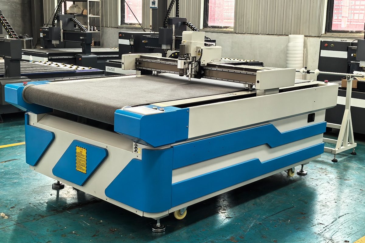
What Are the Main Components of Oscillating Knife Cutting Machines?
Oscillating knife cutting machines are advanced digital cutting systems designed to process a wide range of flexible, semi-rigid, and composite materials with high speed and precision. Unlike laser cutters, which use concentrated heat, or CNC routers, which remove material with a rotating bit, these machines use a rapidly reciprocating blade to separate the material mechanically. This cold-cutting process produces clean edges without burning, melting, discoloration, smoke, or heat-affected zones, making it especially suitable for foam, rubber, leather, textiles, cardboard, gaskets, composites, acoustic panels, and packaging materials.
The performance of oscillating knife cutting machines depends on the coordinated operation of several mechanical, electrical, pneumatic, and digital components. The cutting head generates the high-frequency up-and-down blade motion, while the tool holder and blade determine how effectively the machine handles different material thicknesses and densities. The motion system moves the cutting head accurately along the programmed path, and the cutting table supports and secures the material during processing. Vacuum systems, automatic feeding devices, material alignment tools, and conveyor systems may also be integrated to improve stability and production efficiency.
At the same time, the CNC controller, operating software, servo motors, sensors, and electrical system work together to translate digital designs into precise cutting movements. Safety devices, dust or debris collection systems, lubrication components, and protective structures help maintain reliable operation and protect both the operator and the machine.
Understanding the main components of oscillating knife cutting machines is essential when selecting equipment, evaluating cutting performance, planning maintenance, or troubleshooting production problems. Each component has a specific function, but overall cutting quality depends on how effectively all parts work together. This article explains the major components of oscillating knife cutting machines, their operating principles, their functions, and their influence on cutting accuracy, speed, flexibility, and long-term reliability.
Table of Contents
Machine Frame and Structural Base
The machine frame and structural base form the physical foundation of oscillating knife cutting machines. Every cutting movement, tool vibration, material-handling action, and positioning command depends on the rigidity and stability of this structure. Although the cutting head, control system, and software often receive the most attention, their performance can only be fully realized when the machine is supported by a strong, accurately manufactured frame.
During operation, the cutting head moves rapidly across the working area while the oscillating blade repeatedly travels up and down at high frequency. These movements create dynamic loads, vibration, and changes in direction. If the frame lacks sufficient strength or rigidity, the machine may experience deflection, shaking, resonance, or positioning errors. These problems can reduce edge quality, lower dimensional accuracy, shorten component life, and limit cutting speed.
A well-designed structural base maintains the correct relationship between the cutting table, gantry, motion system, and tool head. It also supports auxiliary equipment such as vacuum pumps, electrical cabinets, conveyor systems, pneumatic components, feeding devices, and material collection units. The following sections explain the principal structural elements of oscillating knife cutting machines and how they influence their performance.
Main Frame Structure
The main frame structure is the load-bearing skeleton of the oscillating knife cutting machine. It connects the machine bed, cutting table, gantry supports, drive system, electrical components, and auxiliary devices into a single integrated assembly. Its primary purpose is to provide the rigidity needed to maintain accurate motion under continuous operating loads.
Main frames are commonly manufactured from welded steel sections, structural steel plates, aluminum profiles, or a combination of these materials. Heavy-duty industrial machines generally use welded steel because it offers high strength, good resistance to deformation, and the ability to support large cutting areas. Smaller or lighter machines may use aluminum profiles to reduce weight and simplify assembly, although additional reinforcement may be required to achieve adequate stiffness.
The geometry of the frame is just as important as the material used. Crossbeams, longitudinal supports, braces, and reinforcing plates are arranged to distribute loads throughout the structure. Proper reinforcement prevents localized bending and torsional deformation when the gantry accelerates, decelerates, or changes direction. Machines designed for high-speed cutting require especially strong structural connections because rapid motion produces greater dynamic forces than slow positioning.
Welded steel frames often undergo stress-relief treatment after fabrication. Welding creates internal stresses that can cause the frame to distort gradually over time. Thermal stress relief, vibration stress relief, or controlled aging can reduce these residual stresses and improve long-term dimensional stability. After stress relief, critical mounting surfaces may be machined to ensure that guide rails, racks, motors, and table components are installed on flat and accurately aligned reference surfaces.
The main frame must also resist vibration generated by the oscillating cutting tool. Although oscillating knives produce less cutting force than a router spindle, their high-frequency motion can still transmit vibration into the machine structure. A rigid frame helps absorb and disperse this energy, preventing it from affecting blade tracking or the movement of the gantry.
Structural design also influences machine accessibility and maintenance. A well-planned frame provides space for wiring, air hoses, vacuum pipes, lubrication lines, control cabinets, and mechanical components. Removable panels and open service areas allow technicians to inspect the drive system, tighten fasteners, replace parts, and clean internal areas without dismantling large sections of the machine.
For machines equipped with automatic feeding or conveyor tables, the main frame must support both cutting and material transport. The structure must keep conveyor rollers, belts, guide rails, and cutting surfaces aligned over the full machine length. Any sagging or misalignment can cause material tracking problems and inaccurate cutting.
The strength of the main frame should be matched to the intended application. Cutting thin fabric requires less structural mass than processing thick rubber, dense foam, multilayer composites, or large sheets. However, even light-material machines benefit from a rigid structure because precision, speed, and repeatability depend on stable mechanical support.
Machine Bed
The machine bed is the central horizontal structure that supports the cutting table and provides the mounting base for the motion system. It defines the working area and plays a major role in maintaining flatness, alignment, and cutting accuracy.
In many oscillating knife cutting machines, the bed consists of a steel framework divided into multiple reinforced sections. These sections distribute the weight of the cutting table, materials, gantry, vacuum system, and optional conveyor equipment. The bed must remain flat and stable across the entire cutting area, especially on large-format machines where small structural deviations can become significant over several meters.
The cutting surface is mounted directly or indirectly on the machine bed. Depending on the machine configuration, the surface may be a stationary vacuum table, a felt-covered cutting bed, a conveyor belt, or a modular table divided into vacuum zones. The bed must support this surface uniformly so that the material remains level beneath the cutting tool.
Flatness is particularly important because oscillating knife cutting relies on controlled blade penetration. If the cutting surface is uneven, the blade may cut too deeply in some areas and fail to cut completely in others. Excessive blade penetration can damage the conveyor belt or cutting mat, increase tool wear, and place unnecessary stress on the tool head. Insufficient penetration can leave sections of the material uncut.
The machine bed also supports vacuum channels, air passages, and zoning structures used to hold materials in place. Vacuum tables are often divided into separate sections that can be activated according to the size and position of the material. The bed must be sufficiently sealed and structurally precise to maintain consistent suction across the working area.
On machines equipped with conveyor systems, the bed supports the conveyor belt and its associated rollers, tensioning devices, guides, and drive mechanisms. The structure must keep the belt level while allowing smooth movement during automatic feeding. Uneven support can cause belt wandering, material shifting, or inconsistent cutting depth.
The motion components may also be mounted along the sides of the bed. Linear guide rails, gear racks, drive belts, and protective covers require straight and accurately machined mounting surfaces. If the bed is twisted or misaligned, the gantry may bind, vibrate, or move unevenly. This can reduce positioning accuracy and accelerate wear on bearings, racks, motors, and guide blocks.
The machine bed may include integrated cable channels, vacuum connections, drainage points, or debris collection areas. These features improve organization and protect sensitive components from dust, fibers, and material fragments. Some designs also incorporate access openings for maintenance or modular sections that simplify transportation and installation.
High-quality machine beds should combine rigidity with practical weight distribution. Excessive weight increases transportation and installation requirements, while insufficient mass can reduce stability. Manufacturers therefore balance structural strength, machine size, expected speed, and production requirements when designing the bed.
Gantry Support Structure
The gantry support structure carries the cutting head and allows it to move across the width of the machine. It is one of the most important structural components because it directly affects positioning accuracy, acceleration, cutting speed, and tool stability.
Most oscillating knife cutting machines use a moving-gantry configuration. In this design, the gantry travels along the length of the machine while the tool carriage moves across the gantry beam. Together, these movements create the X-axis and Y-axis motion needed to follow programmed cutting paths.
The gantry normally consists of a horizontal beam supported by vertical side plates or columns. These supports connect the gantry to the guide rails and drive mechanisms mounted on the machine bed. The entire assembly must remain square and rigid while moving rapidly in both directions.
Gantry beams may be manufactured from steel, aluminum alloy, or specially designed extruded profiles. Steel provides high stiffness and strength but increases moving mass. Aluminum offers lower weight, allowing faster acceleration and reduced motor load, but it must be carefully designed to resist bending and torsion. Some high-performance machines use reinforced or hollow beam structures to combine low weight with high rigidity.
The balance between rigidity and mass is critical. A gantry that is too flexible may deflect during acceleration or when carrying multiple tool modules. This deflection can cause path deviation, poor corner accuracy, and inconsistent blade orientation. A gantry that is unnecessarily heavy may require larger motors and reduce the machine’s acceleration capability.
The gantry must support not only the oscillating knife head but also optional tools such as creasing wheels, drag knives, punching tools, milling spindles, marking pens, cameras, or laser positioning devices. Machines with several tool stations require a stronger gantry because the additional weight increases structural and drive-system loads.
The gantry support structure also contains or supports linear guides, gear racks, timing belts, cable chains, motor mounts, and sensor brackets. These components must remain aligned during continuous motion. Even small alignment errors can create uneven resistance, noise, vibration, or premature wear.
Dual-drive systems are often used on wide-format machines. In this arrangement, motors or drive units operate on both sides of the gantry. Electronic synchronization keeps the two sides moving together and prevents the gantry from twisting. The gantry support structure must be manufactured accurately enough to maintain squareness throughout the full travel range.
The connection between the gantry and the machine bed is another critical design area. Bearings or guide blocks must support vertical, lateral, and torsional loads while allowing smooth movement. Reinforced side plates help transmit acceleration forces into the bed without bending.
A rigid gantry improves cutting quality during rapid direction changes, small-radius curves, sharp corners, and detailed contour cutting. It also helps maintain accurate tool pressure and blade orientation. When the gantry remains stable, the control system can use higher acceleration and cutting speeds without sacrificing precision.
Protective covers are often installed around the gantry guides and transmission components. These covers reduce contamination from foam particles, textile fibers, cardboard dust, adhesive residues, and other debris generated during cutting. Keeping the guide system clean helps preserve motion accuracy and extends component life.
Leveling Feet and Foundation Supports
Leveling feet and foundation supports connect the machine structure to the workshop floor. Although they may appear to be simple components, they play an essential role in machine alignment, load distribution, vibration control, and long-term stability.
Industrial floors are rarely perfectly level. Without adjustable supports, the machine frame could twist or rest unevenly after installation. Leveling feet allow technicians to adjust the height of different points beneath the machine until the bed and guide systems are correctly aligned.
The number and position of the leveling feet depend on the machine’s size, weight, and structural design. Small machines may use four or six supports, while large-format machines may require many support points distributed along the bed. Each foot should carry an appropriate share of the machine load. Uneven load distribution can cause frame deformation or floor damage.
Leveling feet commonly consist of threaded bolts, steel plates, rubber pads, or vibration-damping elements. The threaded design allows precise height adjustment. Locking nuts are used after leveling to prevent movement during operation.
Some supports include rubber or elastomer pads that reduce the transmission of vibration between the machine and the floor. These pads can also improve grip and prevent the machine from shifting. However, the material must be sufficiently firm to avoid excessive movement under dynamic loads.
Heavy-duty or high-speed machines may require foundation bolts or anchor points. Anchoring secures the frame directly to the concrete floor and prevents movement during rapid gantry acceleration. Anchors are especially important for large machines, automated production lines, or installations where nearby equipment generates vibration.
The workshop foundation must be capable of supporting the machine’s total weight. This includes the frame, cutting table, gantry, vacuum pumps, feeding devices, materials, and auxiliary equipment. Weak or uneven flooring can settle over time and disturb machine alignment.
During installation, technicians normally use precision levels or laser measuring instruments to check the machine bed in both longitudinal and transverse directions. Adjustment is performed gradually across all support points. Over-tightening one foot can lift nearby supports and twist the frame, so leveling must be completed carefully.
After the machine has operated for a period, the supports may need to be checked again. Floor settling, vibration, temperature changes, or movement during maintenance can alter the original alignment. Periodic inspection helps maintain table flatness and gantry accuracy.
Foundation supports may also include separate bases for vacuum pumps, air compressors, loading systems, or collection devices. Isolating vibration-producing equipment from the main cutting machine can prevent external vibration from affecting cutting precision.
The machine frame and structural base provide the strength, alignment, and stability required for accurate oscillating knife cutting. The main frame connects all major mechanical and auxiliary systems and resists deformation caused by machine weight, tool vibration, and rapid motion. Its material, reinforcement, stress-relief treatment, and manufacturing precision directly influence the machine’s long-term reliability.
The machine bed supports the cutting surface, vacuum zones, conveyor system, and motion components. It must remain flat and rigid so that the blade maintains a consistent cutting depth across the entire working area. Accurate bed construction also ensures that guide rails and drive components remain properly aligned.
The gantry support structure carries the cutting tools and enables high-speed movement across the machine. A well-designed gantry balances low mass with sufficient rigidity, allowing rapid acceleration without excessive deflection or vibration. Its strength becomes especially important when the machine uses multiple tools or operates over a large cutting area.
Leveling feet and foundation supports ensure that the machine is installed correctly and that its weight is evenly distributed. Proper leveling prevents frame twist, supports accurate gantry movement, and reduces vibration. Together, these structural components create the stable platform needed for high cutting accuracy, smooth operation, efficient production, and extended machine service life.
Gantry and Axis Motion System
The gantry and axis motion system is responsible for moving the cutting tools accurately across the working area of oscillating knife cutting machines. It converts commands from the CNC controller and cutting software into coordinated mechanical motion, allowing the blade to follow straight lines, curves, corners, holes, and complex contours. The accuracy, speed, and stability of this system directly affect cutting quality, dimensional consistency, production efficiency, and the machine’s ability to process detailed designs.
Most oscillating knife cutting machines use a three-axis motion arrangement consisting of the X-axis, Y-axis, and Z-axis. Many machines also include a C-axis, which rotates the cutting tool so that the blade remains aligned with the direction of travel. These axes operate together through guide rails, drive systems, motors, gearboxes, couplings, encoders, and control devices.
Different transmission methods may be used depending on the machine size and performance requirements. Rack-and-pinion systems are common on long travel axes, timing belts are often used for lightweight and high-speed movement, and ball screws may be selected where short-travel precision is especially important. Servo motors are widely used in industrial machines because they provide closed-loop control, while stepper motors may be used in smaller or more economical systems.
A well-designed motion system must balance speed, rigidity, positioning accuracy, load capacity, and maintenance requirements. Every component must also remain correctly aligned to prevent vibration, backlash, uneven movement, and premature wear.
X-Axis Motion System
The X-axis motion system normally moves the gantry along the length of the machine bed. It usually has the longest travel distance of all the motion axes and therefore plays a major role in determining the overall cutting size and productivity of the machine.
In a moving-gantry configuration, the entire gantry assembly travels forward and backward along guide rails installed on both sides of the machine bed. The gantry carries the cutting head, tool carriage, cable chains, pneumatic lines, electrical wiring, and sometimes multiple tool modules. Because of this load, the X-axis drive system must provide sufficient force to accelerate and decelerate the gantry smoothly.
Wide-format oscillating knife cutting machines often use a dual-drive X-axis. In this design, each side of the gantry is driven independently by its own motor, rack, belt, or transmission mechanism. The control system electronically synchronizes both sides to keep the gantry square to the machine bed. If one side moves slightly ahead of the other, the gantry can twist, causing positioning errors, rail wear, vibration, and poor cutting accuracy.
Rack-and-pinion transmission is commonly used for the X-axis because it can provide long travel without the practical length limitations of a ball screw. A gear rack is mounted along each side of the bed, while pinion gears connected to the drive motors engage with the racks. Proper rack alignment, gear engagement, and lubrication are essential for smooth operation.
Some machines use timing belts for the X-axis, particularly when the gantry is lightweight and very high acceleration is required. Timing belts can operate quietly and quickly, but belt tension must be maintained to prevent positioning errors. Larger machines generally require reinforced belts or alternative drive systems because the long belt span can stretch under load.
The X-axis guide rails support the gantry and maintain its movement along a straight path. These rails must be mounted parallel to each other. Even a small difference in alignment can create binding or uneven loading on the guide blocks. For this reason, the frame and machine bed must provide accurately machined rail-mounting surfaces.
Acceleration settings are especially important on the X-axis because the gantry has significant moving mass. Excessive acceleration can cause vibration, frame stress, or loss of synchronization, while acceleration that is too conservative can reduce production efficiency. The controller must therefore match the motion profile to the gantry weight, motor capacity, and structural rigidity.
A stable X-axis allows the machine to maintain high cutting speeds over large sheets or continuous rolls. It is particularly important in applications such as packaging, textiles, foam products, automotive interiors, gaskets, and composite materials, where large cutting areas are common.
Y-Axis Motion System
The Y-axis motion system moves the cutting head or tool carriage across the width of the gantry. It works together with the X-axis to position the blade at any point within the machine’s cutting area.
Unlike the X-axis, which moves the entire gantry, the Y-axis usually moves a smaller carriage. This lower moving mass allows faster acceleration and more responsive directional changes. The Y-axis is frequently involved in detailed contours, short line segments, corners, and repeated lateral movements, so its dynamic performance strongly influences cutting speed and edge quality.
The Y-axis guide rail or rails are mounted on the gantry beam. The tool carriage travels along these rails using linear guide blocks. The beam must remain straight and resist bending because any deflection can change the position or cutting depth of the tool.
Timing-belt transmission is commonly used on the Y-axis because it provides rapid motion, low noise, and relatively low moving weight. The motor may be mounted at one end of the gantry, with a toothed belt transferring motion to the carriage. Belt tensioners and idler pulleys help maintain consistent engagement and prevent belt slippage.
Rack-and-pinion systems may also be used, especially on wide machines or machines carrying several heavy tools. A rack mounted along the gantry beam engages with a pinion on the tool carriage. This arrangement offers high stiffness and is less affected by long travel distances than a conventional belt.
Some precision machines use ball screws on the Y-axis. A rotating screw drives a ball nut connected to the tool carriage. Ball screws can provide excellent positioning accuracy and low backlash, but their speed and practical length may be limited compared with rack or belt systems.
The Y-axis must also support cables, air hoses, vacuum lines, and sensor wiring connected to the tool head. These services are usually routed through flexible cable chains. The cable chain must move freely without creating excessive resistance or interfering with the carriage.
Because the Y-axis changes direction frequently, motor tuning is important. Poorly adjusted acceleration, deceleration, or servo gain can cause overshoot, vibration, or rounded corners. Proper tuning allows the tool to enter and exit curves smoothly while maintaining the programmed path.
The accuracy of the Y-axis also affects the squareness of rectangular parts and the dimensions of narrow features. Any backlash, belt stretch, rail looseness, or structural deflection may appear as contour errors. Regular inspection of the carriage, belts, racks, bearings, and fasteners helps preserve reliable motion.
Z-Axis Motion System
The Z-axis motion system controls the vertical movement of the cutting tool. It raises and lowers the knife so that the machine can enter the material, maintain the correct cutting depth, move between separate contours, and retract safely after completing a cut.
Compared with the X-axis and Y-axis, the Z-axis normally has a much shorter travel distance. However, it requires precise control because even a small vertical error can affect cutting completeness, cutting mat wear, material compression, and tool life.
Before cutting begins, the Z-axis lowers the blade into the material to a programmed depth. The required depth depends on the material thickness, cutting tool, blade length, cutting surface, and desired cutting method. The blade may need to pass completely through the material and penetrate slightly into a sacrificial felt mat or conveyor belt.
If the blade is set too high, the material may not be cut completely. Uncut fibers, films, or backing layers can remain attached, making part separation difficult. If the blade is set too low, it may damage the cutting surface, increase blade wear, overload the tool head, or distort soft materials.
The Z-axis may be driven by a ball screw, lead screw, belt, pneumatic cylinder, or a combination of motorized and pneumatic mechanisms. Motorized Z-axes provide programmable height control and are suitable for machines that process materials of different thicknesses. Pneumatic systems can offer rapid raising and lowering but may provide less precise position control unless combined with sensors or mechanical stops.
Some machines use independent Z-axis controls for multiple tools. For example, oscillating knives, creasing wheel, drag knife, marking pen, and punching tool may each have separate vertical actuation. This allows the controller to activate only the required tool during a particular operation.
Automatic tool-height calibration may be used to improve consistency. A sensor or contact plate detects the tool tip and establishes a reference position. The controller then calculates the required working depth. This reduces manual setup errors and helps compensate for blade replacement or tool changes.
The Z-axis must also respond quickly during interrupted cutting paths. When moving between separate shapes, the tool should retract rapidly to avoid dragging across the material. However, excessively abrupt vertical motion may increase mechanical shock or reduce tool life.
For compressible materials such as foam, felt, rubber, or multilayer fabrics, the Z-axis may also affect cutting pressure. Some tool heads use spring-loaded, pneumatic, or electronically controlled pressure systems to maintain contact while adapting to surface variations.
Accurate Z-axis control is therefore essential for achieving complete cuts, protecting the cutting surface, and maintaining consistent quality across the entire work area.
C-Axis or Tangential Rotation Axis
The C-axis, also called the tangential rotation axis, rotates the cutting tool around its vertical centerline. Its purpose is to keep the blade aligned with the direction of the cutting path.
Oscillating knife blades are directional. Unlike a round rotary cutter, it cannot cut equally well in every orientation. The narrow blade must point in the direction of travel so that its cutting edge enters the material correctly. As the programmed path changes direction, the C-axis rotates the tool to follow the new angle.
The CNC controller calculates the required blade orientation continuously based on the geometry of the cutting path. During curves, the C-axis rotates smoothly while the X-axis and Y-axis move simultaneously. During sharp corners, the tool may pause, lift slightly, rotate to a new angle, and then continue cutting.
Tangential control is particularly important when cutting thick, dense, or rigid materials. If the blade is not correctly aligned, it may bend, drag sideways, enlarge the kerf, damage the edge, or place excessive load on the tool head. Misalignment can also create distorted corners and inaccurate small features.
The C-axis is usually driven by a compact servo motor or stepper motor integrated into the cutting head. A gearbox may be used to increase torque and improve angular control. Bearings support the rotating tool holder and allow it to turn without excessive play.
High-quality C-axis systems offer accurate angular positioning and rapid response. The axis must rotate quickly enough to follow complex contours without slowing overall production. At the same time, it must avoid overshoot or oscillation, which can cause visible marks at corners.
The control software may use different corner-processing strategies. For shallow direction changes, the blade can rotate continuously while moving. For sharp angles, the machine may use lift-and-turn, loop-corner, overcut, or controlled pivoting methods. The most suitable method depends on the blade type, material thickness, contour geometry, and desired edge quality.
C-axis calibration is essential. The actual blade direction must correspond precisely with the angle calculated by the controller. If the zero position is incorrect, the blade will remain slightly misaligned throughout the cut. Calibration may be performed manually or with the help of cameras, sensors, or test patterns.
A precise tangential rotation axis allows oscillating knife cutting machines to produce clean curves, sharp corners, narrow slots, and detailed shapes without twisting or damaging the material.
Linear Guide Rails
Linear guide rails provide the smooth, straight, and rigid movement required by the X-axis, Y-axis, and sometimes the Z-axis. They guide each moving component along a defined path while supporting vertical, lateral, and moment loads.
Typical linear guide systems consist of a hardened rail and one or more recirculating-ball guide blocks. The guide blocks contain rows of steel balls that circulate through internal tracks as the block moves. This design provides low friction, high load capacity, and accurate positioning.
The rails used on oscillating knife cutting machines must be straight, parallel, and securely attached to the supporting structure. X-axis rails are generally mounted along both sides of the machine bed, while Y-axis rails are installed on the gantry beam. Compact rails may also be used within tool heads and vertical motion assemblies.
Rail size and load rating must match the weight and dynamic forces of the moving assembly. The X-axis guide system supports the gantry, while the Y-axis rails support the tool carriage and cutting modules. Machines with heavy milling tools or multiple cutting heads may require larger rails and additional guide blocks.
Preloaded guide blocks are often used to reduce clearance and improve rigidity. Preload removes internal play between the balls and raceways, allowing the guide system to resist vibration and directional changes. Excessive preload, however, can increase friction and motor load.
Lubrication is necessary to reduce wear and protect the rail surfaces. Depending on the machine design, lubrication may be applied manually through grease fittings or automatically through a centralized lubrication system. Insufficient lubrication can cause noise, increased resistance, surface damage, and loss of accuracy.
Cutting debris can also affect rail life. Textile fibers, foam particles, cardboard dust, adhesive residue, and composite dust may enter the guide blocks if the rails are not protected. Bellows, covers, seals, wipers, and regular cleaning help prevent contamination.
Damaged or misaligned rails can cause vibration, jerky movement, uneven resistance, and visible cutting defects. Technicians should inspect the rails for corrosion, scoring, looseness, contamination, and abnormal noise. Guide block fasteners should also be checked periodically.
The quality of the linear guide system has a direct effect on machine repeatability. Smooth rails allow the motors and controller to position the cutting head accurately without overcoming irregular friction or mechanical play.
Rack-and-Pinion Drive System
The rack-and-pinion drive system converts rotary motor motion into linear axis movement. It is widely used on oscillating knife cutting machines, particularly for long X-axis travel and wide Y-axis configurations.
The system consists of a straight gear rack mounted along the axis and a circular pinion gear attached to the motor or gearbox. As the pinion rotates, its teeth engage with the rack and move the gantry or carriage along the machine.
Rack-and-pinion drives are suitable for large-format machines because the rack can be manufactured and installed in multiple sections. This allows nearly unlimited travel length without the critical-speed and sagging problems associated with very long ball screws.
Helical racks are often used in higher-performance machines. Their angled teeth engage gradually, resulting in smoother motion, lower noise, and greater tooth contact than straight racks. This can improve positioning stability during high-speed movement.
Backlash is an important consideration. Backlash is the small amount of free movement that can occur between the rack and pinion teeth when the direction reverses. Excessive backlash can cause dimensional errors, poor corners, and visible mismatches at the beginning and end of closed contours.
Manufacturers may reduce backlash by adjusting the pinion engagement, using spring-loaded pinions, installing dual-pinion systems, or applying software compensation. The pinion must be pressed against the rack firmly enough to minimize clearance but not so tightly that friction and wear increase excessively.
The rack must be installed parallel to the linear guide rail. Poor alignment can cause variable tooth engagement, vibration, noise, and uneven motor load. Sectional racks must also be joined carefully so that the pinion passes smoothly over each connection.
Lubrication protects the teeth from wear and corrosion. Automatic lubrication systems may apply grease at controlled intervals. Excessive grease should be avoided because it can collect dust and debris.
Rack-and-pinion systems provide high speed, good load capacity, and reliable operation over long distances. Their durability and scalability make them one of the most common transmission choices for industrial oscillating knife cutting machines.
Timing-Belt Drive System
Timing-belt drive systems use a toothed belt and matching pulleys to transmit motor power to a moving carriage or gantry. Timing belts are frequently used on Y-axes, lightweight X-axes, tool carriages, and compact cutting machines.
Unlike ordinary friction belts, timing belts have teeth that engage with the pulley grooves. This positive engagement prevents normal slippage and allows the motor rotation to correspond closely with linear movement.
Timing belts are lightweight, quiet, and capable of high acceleration. Their low moving mass makes them suitable for applications where the cutting head must change direction rapidly. They also require little or no lubrication, reducing maintenance and contamination.
The belt material may include rubber, polyurethane, steel cords, fiberglass cords, or aramid reinforcement. Internal tension members reduce stretching and help maintain positioning accuracy. The correct belt type depends on travel length, load, acceleration, environmental conditions, and required precision.
Belt tension is critical. A loose belt may vibrate, skip teeth, or introduce positioning errors. An over-tightened belt can overload motor bearings, pulley shafts, and support bearings. Tensioning devices are therefore used to establish and maintain the correct preload.
Long belt spans can produce elastic deformation during rapid acceleration. This temporary stretching may cause small positioning delays or oscillation. Wider belts, reinforced belts, dual-belt arrangements, or reduced acceleration may be used to control this effect.
Pulley alignment is also important. Misaligned pulleys can cause the belt to track sideways, wear at the edges, or generate abnormal noise. Flanges, guide rollers, and precise shaft alignment help keep the belt centered.
Timing belts should be inspected for cracks, missing teeth, exposed tension cords, contamination, and uneven wear. Belt tension may also need to be checked after installation because new belts can settle during initial operation.
Although timing belts may not offer the same stiffness as rack-and-pinion or ball-screw systems, they provide an effective combination of speed, low noise, low weight, and economical operation for many oscillating knife cutting applications.
Ball-Screw Drive System
Ball-screw drive systems convert rotary motion into precise linear movement using a threaded screw and a recirculating-ball nut. It is commonly used on short-travel axes, Z-axis assemblies, precision tool-positioning mechanisms, and some compact X-axis or Y-axis systems.
The ball nut contains steel balls that circulate between the screw and nut grooves. Rolling contact greatly reduces friction compared with a conventional sliding lead screw. This allows high mechanical efficiency, smooth movement, and accurate positioning.
Ball screws are valued for their rigidity and low backlash. Preloaded ball nuts can eliminate most internal clearance, improving repeatability during direction changes. This makes them suitable for applications requiring precise tool height or fine linear positioning.
The Z-axis often uses a ball screw because its travel is relatively short and cutting depth must be controlled accurately. The screw can hold and move the tool head with minimal vertical play.
Ball screws can also be used for compact cutting machines where the travel distance is limited. However, very long screws can become difficult to support. At high rotational speeds, a long screw may vibrate or whip, limiting axis speed. For this reason, rack-and-pinion or belt drives are generally more practical for large-format machines.
The screw must be aligned accurately with the guide rails. Misalignment can place side loads on the ball nut, increasing friction and wear. Fixed and floating bearing supports are used at the ends of the screw to control axial and radial movement.
Lubrication is necessary for the ball tracks. Dust, fibers, and abrasive particles must be kept away from the screw using seals, bellows, or protective covers. Contamination can damage the precision raceways and reduce service life.
Ball screws may be manufactured with different accuracy grades and lead distances. A smaller lead provides higher resolution and greater mechanical advantage, while a larger lead permits faster linear movement for each motor revolution.
When properly installed and maintained, a ball-screw system provides excellent positioning accuracy, smooth movement, and reliable control for the axes where precision is more important than extremely long travel.
Servo Motors
Servo motors are the most common drive motors in industrial oscillating knife cutting machines. They provide precise speed, position, and torque control through a closed-loop feedback system.
A servo system normally consists of a motor, servo drive, encoder, power supply, and CNC controller. The controller sends a command to the servo drive, which supplies power to the motor. The encoder measures the actual motor position and sends feedback to the drive. The drive continuously compares the commanded position with the actual position and corrects any difference.
This closed-loop operation allows servo motors to maintain high accuracy even when the load changes. For example, if gantry resistance increases slightly due to acceleration, tool weight, or mechanical friction, the servo system can increase torque to maintain the programmed motion.
Servo motors provide high acceleration and can operate over a wide speed range. They are well suited to digital cutting machines, where axes must move rapidly between long straight sections and detailed contours.
The X-axis and Y-axis commonly use AC servo motors. The motor capacity is selected according to gantry weight, carriage weight, travel speed, acceleration, transmission ratio, and friction. Oversized motors may increase cost and moving mass, while undersized motors may overheat or fail to achieve the required performance.
Servo tuning is important for motion quality. Parameters such as position gain, speed gain, acceleration, torque limits, and filtering must match the mechanical system. Poor tuning can cause vibration, overshoot, noise, unstable corners, or delayed response.
Servo drives can also detect abnormal conditions such as overload, encoder failure, excessive position error, overvoltage, or overheating. These alarms help protect the machine and simplify troubleshooting.
Some servo systems support absolute encoders, which retain axis position information after power is switched off. This can reduce the need for repeated homing procedures, although safety checks and reference verification may still be required.
The precision, responsiveness, and fault-monitoring capability of servo motors make them particularly suitable for high-speed, high-accuracy oscillating knife cutting machines.
Stepper Motors
Stepper motors convert electrical pulses into incremental rotational movement. Each input pulse causes the motor shaft to rotate by a defined step angle. They are commonly used in smaller, lower-cost, or less demanding cutting systems.
Traditional stepper motors operate in an open-loop configuration. The controller sends a specific number of pulses and assumes that the motor reaches the commanded position. Because no feedback is used, the system cannot automatically detect a missed step.
Stepper motors provide strong holding torque at low speed and are relatively simple to control. They are often used for Z-axis movement, C-axis tool rotation, light-duty carriages, auxiliary tools, or compact desktop cutting machines.
Their main limitation is that torque decreases as speed rises. If the motor is accelerated too quickly or subjected to excessive resistance, it may lose synchronization. The controller may continue operating without recognizing the position error, resulting in shifted contours or incorrect tool orientation.
Microstepping drives divide each full step into smaller electrical increments. This improves motion smoothness, reduces vibration, and increases command resolution. However, microstepping does not always provide the same practical positioning accuracy as a closed-loop servo system.
Closed-loop stepper motors are also available. These systems include an encoder and can detect position errors. They combine some of the simplicity of stepper technology with improved reliability and feedback control.
Stepper motors may be adequate when cutting speeds, moving loads, and accuracy requirements are moderate. However, servo motors are generally preferred for large industrial machines because they provide better high-speed torque, faster acceleration, and more reliable position control.
Proper motor sizing remains essential. A stepper motor should have sufficient torque reserve to accommodate acceleration, friction, blade rotation, and changes in load without losing steps.
Gearboxes and Couplings
Gearboxes and couplings transfer power from the motor to the rack, belt pulley, ball screw, or rotating tool assembly. They help match motor speed and torque to the requirements of the driven axis.
A gearbox reduces motor speed while increasing output torque. For example, a servo motor may rotate at several thousand revolutions per minute, while the pinion gear requires a lower speed and greater torque. A planetary gearbox can provide this reduction while maintaining compact dimensions and relatively low backlash.
Gear reduction also improves effective positioning resolution. When the motor rotates several times for one output revolution, small motor movements produce smaller changes at the driven axis. However, excessive reduction can limit maximum speed.
Low-backlash gearboxes are important for precision cutting. Mechanical clearance within the gearbox can appear as position error when the axis reverses direction. High-quality planetary gearboxes use precision gears and bearing arrangements to minimize this effect.
The gearbox must be selected according to torque, speed, duty cycle, backlash, mounting orientation, and expected service life. It must also be rigidly mounted to prevent movement under acceleration loads.
Couplings connect two rotating shafts, such as a motor shaft and ball screw, motor shaft and gearbox, or gearbox shaft and pinion. They transmit torque while accommodating small amounts of misalignment.
Flexible couplings can compensate for limited angular, parallel, or axial misalignment. Common designs include jaw couplings, bellows couplings, beam couplings, and disc couplings. The coupling type must provide sufficient torsional stiffness without transferring excessive misalignment forces to bearings.
A coupling with too much flexibility may reduce motion responsiveness, while a rigid coupling installed on misaligned shafts may cause vibration, bearing damage, or premature wear. Correct alignment is therefore still necessary even when flexible couplings are used.
Loose coupling screws or damaged elastic inserts can create backlash and irregular motion. Periodic inspection should include checking fasteners, wear, cracking, noise, and shaft alignment.
Together, gearboxes and couplings ensure that motor power is transmitted efficiently and accurately to the axis drive system.
Encoders and Position-Feedback Devices
Encoders and position-feedback devices measure the movement or position of motors, axes, and rotating tools. They allow the control system to verify that the machine follows commanded motion accurately.
A rotary encoder is commonly installed on the rear of a servo motor. It measures motor shaft rotation and sends electrical signals to the servo drive. The drive uses these signals to calculate position, speed, and direction.
Incremental encoders generate pulses as the shaft rotates. The controller determines movement by counting these pulses. After power is lost, an incremental system normally requires a homing procedure to establish the machine reference position.
Absolute encoders assign a unique value to each shaft position. They can retain or recover position information after power loss. This reduces setup time and may improve restart capability, particularly on automated production lines.
The C-axis may also use an encoder to verify blade orientation. Accurate angular feedback helps ensure that the cutting edge remains aligned with the programmed direction.
Some machines include linear encoders mounted directly along an axis. Unlike a motor encoder, which measures shaft rotation, a linear encoder measures the actual position of the moving gantry or carriage. This can compensate for errors caused by gearbox backlash, belt stretch, rack variation, thermal expansion, or coupling deformation.
Home sensors and limit switches are additional position-feedback devices. A home sensor establishes the axis reference point during startup. Limit switches prevent the axis from moving beyond its safe travel range. Proximity sensors, photoelectric sensors, and mechanical switches may be used depending on the machine design.
Tool-height sensors help establish the Z-axis reference position, while material-detection sensors may measure surface height or confirm material presence. Some machines also use camera systems for visual registration and contour correction.
Feedback signals must remain stable and protected from electrical interference. Shielded cables, correct grounding, secure connectors, and proper cable routing help prevent signal loss or false readings.
A damaged encoder or sensor can cause position errors, unexpected stops, alarm messages, or unstable motion. Diagnostic systems may monitor feedback consistency and stop the machine if the commanded and actual positions differ beyond an allowable limit.
Accurate feedback devices are essential for closed-loop control, reliable homing, blade orientation, safety monitoring, and repeatable cutting performance.
The gantry and axis motion system enables oscillating knife cutting machines to convert digital cutting files into accurate physical movement. The X-axis moves the gantry along the machine bed, while the Y-axis moves the cutting carriage across the gantry. The Z-axis controls blade height and cutting depth, and the C-axis rotates the directional blade so that it remains aligned with the cutting path.
Linear guide rails provide rigid and low-friction support for the moving assemblies. Rack-and-pinion drives are especially suitable for long travel and large-format machines, while timing belts offer lightweight, quiet, and high-speed movement. Ball screws provide high rigidity and low backlash for shorter axes and precise vertical positioning.
Servo motors deliver closed-loop control, strong high-speed performance, and rapid response, making them the preferred choice for industrial machines. Stepper motors offer a simpler and more economical solution for light-duty axes and auxiliary functions. Gearboxes increase torque and improve motion resolution, while couplings transfer motor power and accommodate minor shaft misalignment.
Encoders, home sensors, limit switches, and other feedback devices allow the control system to monitor actual position and detect errors. The performance of the complete motion system depends on accurate installation, correct motor tuning, controlled backlash, proper lubrication, stable feedback signals, and regular maintenance.
When all these components operate together correctly, the machine can achieve smooth acceleration, precise blade orientation, accurate contours, clean corners, and consistent repeatability. A high-quality gantry and axis motion system therefore forms one of the most important foundations of cutting accuracy, speed, productivity, and long-term machine reliability.
Oscillating Knife Cutting Head
The oscillating knife cutting head is the primary working unit of oscillating knife cutting machines. It holds the blade, generates the rapid reciprocating cutting motion, controls blade orientation, and regulates how the tool enters and passes through the material. While the gantry and motion system move the tool along the programmed contour, the cutting head performs the actual separation of the material.
Unlike a drag knife, which depends mainly on forward movement to pull a stationary blade through the workpiece, oscillating knives drive the blade rapidly up and down. This motion reduces cutting resistance and allows the machine to process thicker, denser, and more elastic materials. Typical applications include cutting foam, rubber, leather, corrugated cardboard, gasket materials, textiles, insulation, felt, honeycomb panels, composites, and multilayer fabrics.
The performance of the cutting head depends on several closely coordinated components. The cutting head body provides structural support, the oscillation motor supplies driving power, and the eccentric mechanism converts rotary motion into reciprocating blade movement. The blade guide maintains alignment, while the lifting and tangential rotation mechanisms control vertical positioning and blade direction. Cutting pressure, penetration depth, oscillation frequency, and stroke length must also be matched to the material.
Well-designed oscillating knife cutting heads should offer high rigidity, low vibration, precise blade guidance, reliable cooling, rapid response, and convenient tool replacement. Its design strongly influences edge quality, cutting speed, blade life, machine productivity, and the range of materials the machine can process.
Cutting Head Body
The cutting head body is the main structural housing of the oscillating knife tool. It supports and aligns the oscillation motor, eccentric transmission, blade holder, guide components, bearings, vertical lifting mechanism, and tangential rotation assembly. It also connects the complete tool module to the machine carriage.
The body must be rigid enough to resist vibration and deformation during high-frequency operation. Although the blade is relatively small, the rapid reciprocating movement produces repeated dynamic forces. If the head body flexes, the blade may move laterally, deviate from the programmed line, or produce uneven edges. Structural rigidity is especially important when cutting thick foam, dense rubber, composite panels, or multiple material layers.
Cutting head bodies are commonly manufactured from aluminum alloy, steel, or a combination of both materials. Aluminum is widely used because it is lightweight, corrosion-resistant, and easy to machine accurately. Reducing head weight lowers the load on the Y-axis carriage and allows faster acceleration. However, critical bearing seats, tool interfaces, and highly loaded areas may use hardened steel inserts or reinforced sections.
The body must maintain accurate alignment between the oscillation mechanism and the blade centerline. Even a small angular error can cause the blade to rub against the guide, generate heat, or experience unequal loading. Precision machining of bearing bores, mounting surfaces, and guide channels is therefore essential.
Heat management is another important function of the head body. The oscillation motor and bearings generate heat during continuous operation. Some tool heads rely on natural air circulation, while others include cooling fins, fans, compressed-air passages, or internal airflow channels. Effective cooling helps maintain stable dimensions and protects lubricants, seals, motor windings, and electronic components.
The head body may also provide passages for electrical cables, pneumatic hoses, sensor wires, and lubrication lines. These services must be routed securely so that they do not interfere with the rotating or reciprocating mechanisms. Cable strain relief and flexible connections are particularly important because the tool head moves continuously during production.
Many machines use modular cutting heads that can be removed or replaced without dismantling the complete tool carriage. Quick-release clamps, locating pins, electrical connectors, and pneumatic couplings simplify tool changes and maintenance. This is useful when the machine switches between oscillating knives, creasing wheels, rotary cutters, milling tools, or punching devices.
The head body may include protective covers to prevent dust, fibers, foam particles, and adhesive residue from entering the mechanism. These contaminants can damage bearings, increase friction, and reduce tool accuracy. Sealed or semi-sealed designs are therefore preferred in dusty production environments.
A well-manufactured cutting head body provides the stable foundation required for precise oscillation, accurate tangential rotation, controlled blade penetration, and long-term reliability.
Oscillation Motor
The oscillation motor provides the power needed to move the blade rapidly up and down. It is one of the most important components of the cutting head because its speed, torque, cooling capacity, and durability determine the available oscillation performance.
Depending on the head design, the oscillation motor may be a brushless DC motor, AC motor, servo motor, high-speed electric motor, or pneumatic motor. Electrically driven heads are common because they offer controllable speed, consistent output, and convenient integration with the CNC system.
Brushless motors are frequently used in industrial cutting heads. Unlike brushed motors, they do not rely on physical brushes that wear during operation. This reduces maintenance, improves reliability, and allows the motor to operate efficiently at high rotational speeds.
The motor does not normally move the blade directly. Instead, it rotates the eccentric drive mechanism, which converts the motor’s continuous rotation into vertical reciprocating movement. The relationship between motor speed and eccentric geometry determines the oscillation frequency and blade stroke.
Motor torque must be sufficient to overcome the resistance of the eccentric mechanism, blade guide, and material being cut. Dense materials place greater load on the blade, especially during deep penetration or high-speed contour cutting. If the motor is underpowered, oscillation speed may decrease under load, leading to rough edges, incomplete cutting, or overheating.
The control system may allow the operator to adjust motor speed according to the material. A lower oscillation rate may be suitable for thin fabrics or delicate materials, while thick rubber, foam, or gasket sheets may require higher frequency and greater cutting energy.
Continuous-duty performance is important in production environments. The motor may operate for many hours with few interruptions, so its bearings, windings, insulation, and cooling system must withstand sustained thermal and mechanical stress.
Overheating can reduce motor life and affect cutting consistency. For this reason, some cutting heads include temperature sensors that allow the controller to issue warnings or stop the machine if the motor exceeds a safe limit. Air cooling, fans, or compressed-air assistance may be used to remove heat.
The motor must also be dynamically balanced. Imbalance at high speed can generate vibration, increase bearing load, loosen fasteners, and reduce edge quality. Precision motor shafts and balanced rotating components help ensure smooth operation.
Noise is another factor. High-frequency cutting heads naturally generate mechanical sound, but a high-quality motor and transmission system can reduce unnecessary vibration and noise. Abnormal sound may indicate bearing wear, eccentric damage, loose fasteners, or insufficient lubrication.
The oscillation motor should be selected as part of the complete tool-head system rather than as an isolated component. Its speed range, torque curve, dimensions, mounting arrangement, cooling method, and compatibility with the controller must all match the intended cutting applications.
Eccentric Drive Mechanism
The eccentric drive mechanism converts the rotary motion of the oscillation motor into the rapid linear movement of the blade. It is the mechanical link between the motor shaft and the blade holder.
A typical eccentric mechanism includes an eccentric cam, offset crank, connecting rod, bearing, slider, and reciprocating shaft. As the motor rotates, the offset center of the eccentric component moves in a circular path. The connecting mechanism transforms this circular motion into an alternating upward and downward movement.
The amount of eccentric offset determines the blade stroke. A greater offset produces a longer stroke, while a smaller offset produces a shorter stroke. The geometry must be manufactured accurately to maintain consistent movement and prevent uneven loading.
Because the mechanism operates at high speed, its bearings and sliding surfaces are exposed to repeated cyclic forces. High-quality bearings, hardened contact surfaces, and proper lubrication are essential. Wear in the eccentric bearing or connecting components can create clearance, vibration, and irregular blade movement.
The mechanism must also be balanced to minimize lateral forces. Ideally, the blade should move vertically with very little side-to-side motion. Excessive lateral movement can increase friction between the blade and guide, widen the cutting kerf, damage delicate materials, or cause blade breakage.
Some cutting heads use counterweights or balanced crank structures to reduce vibration. These components oppose the inertial forces generated by the reciprocating blade assembly. Better balance allows higher oscillation frequencies while reducing stress on the tool carriage and machine structure.
The eccentric mechanism must be sufficiently rigid to transmit force without elastic deformation. At the same time, its moving parts should be lightweight to reduce inertia. This balance allows the blade to accelerate and reverse direction rapidly.
Lubrication may be permanent, grease-based, oil-based, or supplied through a maintenance port. Sealed bearings reduce contamination and maintenance requirements, but they must still be replaced when their service life is reached.
The eccentric drive mechanism is normally enclosed within the cutting head body to protect operators and prevent debris from entering. Covers should remain securely installed because exposed high-speed components can present a serious safety risk.
Signs of eccentric mechanism wear may include increased noise, reduced oscillation amplitude, irregular cutting, excessive heat, or visible vibration. Early inspection can prevent secondary damage to the motor, blade guide, or bearings.
A precisely manufactured and properly maintained eccentric mechanism ensures that motor power is converted into smooth, repeatable, and efficient blade movement.
Oscillation Frequency
Oscillation frequency refers to the number of complete up-and-down blade cycles performed within a given period, usually expressed in strokes per minute, cycles per minute, or hertz. It is one of the main operating parameters of oscillating knife cutting heads.
The frequency determines how often the blade penetrates and withdraws from the material as the tool moves along the cutting path. A higher frequency produces more cutting actions over the same travel distance, which can reduce resistance and improve edge smoothness.
High oscillation frequencies are particularly useful when cutting dense foam, rubber, thick cardboard, felt, or multilayer textiles. The rapid motion repeatedly shears the material instead of forcing the blade through it in one continuous movement.
However, the highest available frequency is not always the best setting. Excessive frequency can generate heat, increase vibration, accelerate bearing wear, and shorten blade life. It may also cause certain soft or adhesive materials to melt, smear, or stick to the blade.
Thin fabrics, films, and delicate materials may require a moderate frequency to prevent pulling, fraying, or distortion. The operator should therefore select a frequency based on material density, thickness, elasticity, fiber structure, adhesive content, and the required edge quality.
Frequency must also be coordinated with cutting speed. If the machine moves quickly while the oscillation frequency is too low, the distance between blade strokes becomes larger. This can produce rough edges or incomplete separation. Increasing frequency allows the blade to perform more cutting actions per unit of travel.
The ideal setting is usually established through sample testing. Operators may begin with a manufacturer-recommended baseline and adjust the frequency while evaluating edge quality, cutting resistance, blade temperature, and production speed.
Some machines allow the frequency to be changed directly through the control software. Advanced systems may store frequency settings in a material library so that the correct value is loaded automatically when a particular material and tool are selected.
Frequency stability is as important as maximum frequency. If motor speed fluctuates under load, edge quality may vary within the same part. The motor and drive system must therefore maintain the commanded speed during changes in material resistance.
The mechanical system also has practical frequency limits. Bearings, eccentric components, blade holders, and guides must withstand the repeated acceleration and reversal forces. Operating above the rated frequency can cause premature wear or failure.
A properly selected oscillation frequency reduces cutting force, improves edge quality, supports higher processing speeds, and helps extend blade life.
Blade Stroke
Blade stroke is the total vertical distance traveled by the blade during one oscillation cycle. It is normally determined by the eccentric offset or crank geometry within the cutting head.
A short stroke produces rapid, controlled blade movement and is often suitable for thin materials, fabrics, paperboard, leather, and fine-detail cutting. Because the moving mass travels a smaller distance, the head can usually operate at a higher frequency.
A long stroke provides greater vertical movement and cutting action. It is more suitable for thick foam, rubber, corrugated materials, honeycomb panels, insulation, and multilayer products. The longer movement helps the blade pass through a greater thickness and clear material from the cutting zone.
Stroke length should not be confused with maximum cutting thickness. The blade length, cutting depth, tool design, and material behavior also influence how thick a material the machine can cut. A blade may remain partially inside the material throughout the oscillation cycle, so the full material thickness does not always need to equal the stroke length.
However, the stroke must be sufficient to create effective shearing action. If it is too short for a dense or thick material, the blade may drag rather than cut efficiently. This can increase lateral force, heat, and edge roughness.
A stroke that is unnecessarily long can also create disadvantages. It increases the acceleration distance of the reciprocating components, producing greater inertial force and vibration. Longer strokes may reduce the maximum safe frequency and place more load on bearings and guides.
Some cutting heads have a fixed stroke determined by their mechanical design. Other heads may be available in different versions, such as short-stroke and long-stroke models. A small number of advanced systems may allow mechanical or electronic stroke adjustment.
The choice of stroke should consider material thickness, density, compressibility, cutting speed, blade shape, and desired quality. Thin, detailed materials generally benefit from a short, fast stroke, while thick, resilient materials often require a longer and more powerful cutting action.
Blade stroke must also remain consistent. Wear in the eccentric mechanism, connecting rod, bearings, or blade holder can reduce or destabilize the effective stroke. This may lead to inconsistent cutting depth or increased vibration.
Manufacturers often specify the stroke range and recommended applications for each cutting head. Selecting the correct head prevents operators from attempting to process materials beyond the tool’s mechanical capability.
The correct blade stroke improves cutting efficiency, reduces tool load, and ensures that the oscillating movement is appropriate for the physical characteristics of the material.
Blade Guide
The blade guide supports the oscillating blade and keeps it aligned during high-frequency movement. It prevents the blade from bending or moving excessively sideways as it penetrates the material.
Because oscillating blades are usually thin and narrow, they can flex under lateral cutting forces. This is especially likely when cutting thick, dense, elastic, or layered materials. The blade guide provides support near the cutting zone, reducing unsupported blade length and improving stability.
A typical blade guide may include precision bushings, guide slots, rollers, bearings, or hardened inserts. The guide opening is manufactured to closely match the blade thickness while still allowing free vertical movement.
The clearance between the blade and guide is critical. Excessive clearance allows lateral movement, which can create wider kerfs, inaccurate contours, angled edges, and premature blade fatigue. Insufficient clearance increases friction, heat, and wear.
The guide must remain accurately aligned with the oscillation shaft and blade holder. Misalignment can force the blade against one side of the guide, producing uneven wear and additional motor load.
Blade guides are often made from hardened steel, wear-resistant alloy, carbide, engineering polymer, or other low-friction materials. The appropriate material depends on oscillation speed, blade type, cutting load, and contamination level.
Some heads use replaceable guide inserts. These inserts can be changed when worn without replacing the complete tool head. This reduces maintenance cost and helps restore cutting accuracy.
Debris accumulation around the blade guide can interfere with movement. Fibers, adhesive residue, rubber particles, and foam dust may collect in the guide opening. Compressed air, brushes, vacuum extraction, or regular manual cleaning may be required.
Lubrication must be used carefully. While lubrication can reduce guide friction, excessive oil or grease may contaminate the workpiece or attract dust. Some guides are designed to operate dry, while others use small quantities of specialized lubricant.
The guide also influences blade temperature. Friction between the blade and guide can generate heat, particularly at high frequency. A worn, dirty, or misaligned guide can cause rapid temperature increase.
Operators should inspect the guide when replacing blades. Visible scoring, looseness, deformation, or uneven wear may indicate that the guide requires adjustment or replacement.
A stable blade guide allows the knife to follow the programmed path accurately and produce vertical, clean, and consistent cut edges.
Tool-Lifting Mechanism
The tool-lifting mechanism raises and lowers the oscillating knife relative to the material. It enables the blade to enter the workpiece, retract between separate contours, avoid obstacles, and move safely when cutting is not required.
The lifting function may be controlled by a pneumatic cylinder, electric actuator, servo-driven Z-axis, solenoid, cam mechanism, or a combination of these systems. The selected method depends on the required speed, precision, force, and stroke.
Pneumatic lifting is common because it provides fast response and a simple mechanical design. Compressed air drives a cylinder that lowers or raises the tool. Adjustable pressure regulators may control the downward force.
Motorized lifting provides more precise and programmable vertical positioning. A servo motor or stepper motor can move the tool to specific heights, making it suitable for materials with different thicknesses or applications requiring accurate depth control.
The lifting mechanism must operate quickly because the tool may need to rise and descend many times during one cutting program. Slow lifting increases non-cutting time and reduces productivity, especially when the layout contains many small, separate parts.
However, the movement should not be so abrupt that it creates excessive shock. Repeated impact can loosen fasteners, damage bearings, or reduce the life of the blade holder. Acceleration and deceleration may therefore be controlled electronically or damped mechanically.
The mechanism must provide sufficient clearance when the tool is raised. The blade should pass safely over the material, clamps, conveyor joints, previously cut parts, and surface variations.
During cutting, the lifting assembly must remain rigid. Any vertical looseness can cause inconsistent penetration depth. Preloaded bearings, linear guides, bushings, and mechanical stops may be used to remove play.
Some machines allow individual lifting of multiple tools mounted on the same carriage. The controller activates only the tool required for the current process, such as oscillating knives, creasing wheel, drag knife, or marking pen.
Position sensors may confirm whether the tool is raised or lowered. These sensors improve safety and allow the controller to detect a failed cylinder, obstruction, or incomplete movement.
Maintenance includes checking cylinders, seals, guide components, air pressure, lubrication, fasteners, and sensor operation. Air leaks or worn guides can reduce lifting speed and positional accuracy.
A reliable tool-lifting mechanism minimizes non-cutting time, prevents unwanted blade marks, and ensures consistent entry into the material.
Tangential Blade-Rotation Mechanism
The tangential blade-rotation mechanism turns the complete knife assembly around its vertical axis so that the blade remains aligned with the direction of movement. It performs the mechanical function of the C-axis.
Because oscillating knives have a defined cutting edge, it must point toward the direction in which the tool is traveling. If the blade is not aligned, it will be forced sideways through the material. This can bend the blade, damage the edge, distort the contour, and overload the cutting head.
The rotation mechanism usually includes a servo motor or stepper motor, gearbox, drive belt or gear set, bearings, rotating shaft, and tool holder. The motor receives angular commands from the CNC controller and rotates the blade to the calculated orientation.
High angular accuracy is essential. Even a small orientation error can become visible when cutting thick material or small-radius curves. The mechanism must therefore have low backlash and high torsional rigidity.
A planetary gearbox may be used to increase torque and improve angular resolution. Timing belts or precision gears may transfer power from the motor to the rotating tool shaft. Each method must be designed to minimize mechanical clearance.
Bearings support the rotating shaft and resist radial, axial, and moment loads. They must allow smooth rotation while preventing lateral movement. Worn bearings can cause blade wobble or angular inconsistency.
During curved cutting, the rotation axis moves continuously in coordination with the X-axis and Y-axis. During sharp direction changes, the machine may stop, lift the blade slightly, rotate it, and then resume cutting.
Different corner strategies may be used. Tangential corner rotation creates a sharp angle by changing blade orientation at the corner. Looping moves the tool outside the final contour to turn gradually. Overcutting extends the cut slightly to complete the corner. The best method depends on material thickness, blade shape, and quality requirements.
The mechanism must rotate rapidly enough to avoid limiting overall cutting speed. However, excessive angular acceleration can cause overshoot, vibration, or tool stress. Proper motor tuning is therefore important.
The zero-angle position must be calibrated so that the physical blade direction matches the controller’s reference angle. A calibration error will affect every contour cut by the tool.
The blade holder must also clamp the blade securely. Any movement between the blade and holder defeats the accuracy of the rotation mechanism. Tool holders may use screws, collets, clamps, or quick-change cartridges.
A precise tangential rotation mechanism enables the machine to cut sharp corners, smooth curves, narrow slots, and complex shapes with clean and accurate edges.
Cutting-Pressure and Penetration Control
Cutting pressure and penetration control determine how deeply and forcefully the oscillating blade enters the material. These functions are essential for achieving complete cuts without unnecessarily damaging the blade, workpiece, cutting mat, or conveyor belt.
Penetration depth refers to the vertical position of the blade relative to the material and cutting surface. The blade normally passes through the full thickness of the material and enters the sacrificial surface by a small controlled amount.
If penetration is insufficient, the lower layer of the material may remain attached. This is common with woven fabrics, coated materials, adhesive-backed products, or multilayer sheets. Incomplete cutting increases manual finishing and may damage parts during removal.
Excessive penetration causes the blade to cut deeply into the felt mat or conveyor belt. This accelerates surface wear, increases cutting resistance, creates more debris, and can bend or break the blade.
Depth may be controlled through a programmable Z-axis, mechanical stop, tool-height adjustment screw, pneumatic cylinder, servo actuator, or pressure-regulated system. Advanced machines store depth settings for different materials and tool types.
Automatic tool-height sensing can establish the exact blade tip position after installation. The tool touches a reference sensor or calibration pad, allowing the controller to calculate the required working height.
Material thickness measurement may also be used. A sensor, pressure foot, probe, or camera can identify the upper surface of the material and compensate for thickness variation.
Cutting pressure is especially important for compressible materials. Foam, felt, rubber, insulation, and layered textiles may deform when the tool presses downward. Excessive pressure can compress the material and change the final dimensions, while insufficient pressure can reduce cutting stability.
Some cutting heads use pneumatic pressure regulation. The air pressure applied to the cylinder determines the downward force. Operators can adjust this value according to material density and thickness.
Spring-loaded mechanisms may allow the tool to follow slight surface variations while maintaining a controlled force. Servo-controlled systems provide more precise and programmable pressure or position management.
A pressure foot may be installed around the blade to hold the material flat near the cutting point. This reduces lifting, stretching, or shifting, particularly when processing textiles, foam, or soft sheets. The foot pressure must be adjusted carefully to avoid marking or compressing the material.
Penetration control must also account for cutting-surface wear. Felt mats and conveyor belts become grooved over time, changing the local support height. Automatic table mapping or surface compensation can correct for these variations.
Blade wear affects effective cutting depth. As the blade tip becomes shorter or rounded, the original height setting may no longer produce a complete cut. Regular inspection and recalibration are therefore necessary.
Pressure and penetration settings should be tested together with cutting speed, oscillation frequency, stroke length, and blade type. A change in one parameter can affect the others. For example, increasing cutting speed may require greater penetration consistency or higher oscillation frequency.
Correct pressure and penetration control produce complete cuts, protect the cutting surface, reduce blade breakage, and maintain accurate part dimensions.
The oscillating knife cutting head is the component that performs the machine’s actual cutting action. Its body provides the rigid structural support required to keep the motor, eccentric mechanism, blade holder, guide, lifting assembly, and rotation axis correctly aligned.
The oscillation motor generates rotary power, while the eccentric drive mechanism converts that rotation into rapid vertical blade movement. Oscillation frequency determines how many cutting cycles occur within a given period, and blade stroke determines the distance traveled during each cycle. These parameters must be matched to the thickness, density, elasticity, and structure of the material.
The blade guide supports the knife and limits lateral deflection, helping the machine produce accurate contours and vertical edges. The tool-lifting mechanism raises and lowers the knife between cutting paths, reducing non-cutting time and preventing unwanted surface marks.
The tangential blade-rotation mechanism keeps the cutting edge aligned with the direction of travel. Accurate angular control is essential when cutting curves, corners, slots, and complex geometries, especially in thick materials.
Cutting-pressure and penetration control regulate how the blade enters and passes through the workpiece. Proper adjustment ensures complete separation while minimizing blade wear, material compression, and damage to the cutting surface.
The cutting head must combine structural rigidity, low moving mass, accurate alignment, stable frequency, effective cooling, and reliable control. Regular inspection of bearings, guides, blades, eccentric components, sensors, and lifting mechanisms is essential for maintaining performance.
When all cutting-head components operate correctly, the machine can cut a wide variety of flexible and semi-rigid materials with clean edges, high speed, precise dimensions, and consistent repeatability. The design and condition of the oscillating knife cutting head therefore have a direct influence on machine capability, production efficiency, operating cost, and finished-product quality.
Knife Blades and Blade Holders
Knife blades and blade holders are the parts of oscillating knife cutting machines that directly contact the material. Their design, material, geometry, installation accuracy, and condition have a major influence on cutting quality, production speed, edge smoothness, dimensional accuracy, and tool life. Even when the machine frame, motion system, and cutting head are operating correctly, an unsuitable or poorly installed blade can still produce rough edges, incomplete cuts, excessive drag, distorted corners, or premature tool failure.
Oscillating knife cutting machines can process many materials, including foam, rubber, leather, textiles, felt, corrugated cardboard, gasket sheets, insulation, honeycomb panels, composites, and packaging materials. However, these materials differ greatly in thickness, density, hardness, elasticity, fiber structure, and abrasiveness. For this reason, there is no single blade that performs equally well in every application.
Blade selection involves more than choosing a sharp edge. The operator must consider blade material, shape, length, thickness, cutting angle, tip geometry, and compatibility with the blade holder. The amount of blade exposed from the holder must also be adjusted carefully to provide sufficient cutting depth without allowing unnecessary flexing.
The blade holder must clamp the tool securely, maintain correct alignment, and transfer oscillating and rotational motion without looseness. Blade-wear monitoring is equally important because cutting performance gradually declines as the edge becomes rounded, chipped, contaminated, or shortened.
Selecting and maintaining the correct blade system allows the machine to cut efficiently with lower resistance, cleaner edges, reduced material deformation, and fewer production interruptions.
Blade Materials
Blade material determines hardness, toughness, wear resistance, corrosion resistance, heat resistance, and the ability to maintain a sharp cutting edge. The most common blade materials used in oscillating knife cutting machines include carbon steel, high-speed steel, tool steel, stainless steel, tungsten carbide, and specially coated alloys.
Carbon steel blades are widely used because they are economical, sharp, and easy to manufacture in many shapes. They can provide excellent initial cutting performance for paperboard, thin foam, leather, fabric, felt, and other relatively soft materials. However, carbon steel is more susceptible to corrosion and may lose sharpness faster when cutting abrasive or dense materials.
High-speed steel blades offer greater hardness and heat resistance than ordinary carbon steel. They maintain their cutting edge under higher mechanical loads and are suitable for thicker rubber, dense foam, gasket materials, plastics, and multilayer products. Their improved durability makes them useful in continuous industrial production, although they generally cost more than standard steel blades.
Tool steel blades are designed to provide a balance of hardness, toughness, and wear resistance. Depending on the alloy and heat treatment, they can resist chipping while maintaining a sharp edge. These blades are often selected for materials that produce high cutting resistance or contain reinforcing fibers.
Stainless steel blades provide better corrosion resistance and are useful when processing damp materials, food-contact packaging, medical products, or materials that may release corrosive substances. Stainless steel may not always offer the same edge retention as specialized tool steels, but it can be advantageous in hygienic or moisture-sensitive environments.
Tungsten carbide blades provide exceptional hardness and wear resistance. They are particularly suitable for abrasive materials such as fiberglass, carbon-fiber composites, reinforced gaskets, mineral-fiber insulation, and certain technical textiles. Carbide blades can remain sharp much longer than steel blades, reducing tool-change frequency.
However, carbide is more brittle than steel. It can chip or break if the blade is subjected to impact, excessive lateral force, incorrect installation, or sudden contact with the cutting table. Carbide blades therefore require precise tangential alignment, stable blade guidance, and careful handling.
Some blades use a steel body with a carbide cutting edge. This design combines the toughness of steel with the wear resistance of carbide. It can reduce the risk of complete blade breakage while extending edge life.
Surface coatings may also be applied to blades. Titanium nitride, titanium carbonitride, diamond-like carbon, and other low-friction or wear-resistant coatings can improve hardness, reduce material adhesion, and extend service life. Coated blades are useful when cutting sticky, abrasive, or resin-containing materials.
Blade material should be selected according to the workpiece rather than cost alone. A less expensive blade may need frequent replacement and create more downtime, while a premium blade may reduce operating costs through longer service life and more consistent cutting.
Material compatibility must also be considered. Adhesive-backed products may leave residue on certain blade surfaces, while abrasive composites can rapidly dull standard steel. Testing several blade materials under actual production conditions is often the most reliable way to identify the best option.
Blade Shapes
Blade shape determines how the cutting edge enters the material, how much resistance it encounters, how easily it turns through curves, and what type of edge it produces. Oscillating knife cutting machines use many blade geometries because different materials and contours require different cutting actions.
A pointed straight blade is one of the most common types. It has a narrow body and a sharp tip that penetrates the material easily. This blade is suitable for foam, rubber, corrugated cardboard, felt, leather, insulation, and many general-purpose cutting applications.
Double-edged blades have cutting edges on both sides. Depending on the machine and cutting strategy, this design may reduce resistance during changes in direction or allow longer service life. It may also provide symmetrical cutting behavior when the blade travels forward and backward.
Single-edged blades have one sharpened side and one flat or less-sharpened side. They can provide more controlled cutting and may influence which side of the material receives the cleaner edge. The operator must install the blade in the correct orientation.
Flat-tip blades are used when a sharp point is unnecessary or when the operator wants to reduce the risk of penetrating too deeply into the cutting mat. However, they may require greater initial force to enter the material.
Spear-point blades have cutting edges that meet at a central point. This symmetrical geometry can provide stable penetration and is often used for thicker, denser, or multilayer materials.
Hook blades have a curved or hooked cutting edge. They may be useful for certain textiles, carpets, flexible films, or materials that need to be pulled toward the cutting edge. However, their directional behavior requires careful tangential control.
Chisel blades have an angled tip and are sometimes used for V-cuts, bevels, grooves, or specialized edge preparation. The geometry can remove or separate material at a controlled angle rather than producing a purely vertical cut.
Narrow blades are preferred for small-radius curves, detailed patterns, narrow slots, and intricate contours. Their reduced width allows easier rotation and less material displacement. However, they are more flexible and may bend when cutting thick or dense materials.
Wide blades provide greater stiffness and are suitable for long straight cuts, thick foam, heavy rubber, or applications where edge verticality is more important than small-radius capability. Their greater width can limit turning performance.
Some blades have serrated or micro-serrated edges. These designs can improve cutting performance in fibrous, woven, or tough materials by creating a sawing action. However, they may leave a different edge texture and may not be suitable for all finished-product requirements.
Specialized blades may also be designed for kiss cutting, bevel cutting, perforation, grooving, notching, or cutting layered structures without penetrating the backing layer.
The blade shape must be compatible with the cutting path. A blade that works well on long straight contours may struggle with tight corners, while a highly flexible detail blade may deflect in thick material. Selecting the correct shape requires balancing penetration, stiffness, maneuverability, edge quality, and material behavior.
Blade Length
Blade length refers to the total length of the cutting blade or the usable distance from the holder to the tip. It affects maximum cutting depth, blade stiffness, vibration, and the risk of deflection.
Long blades are required for thick materials such as foam blocks, multilayer felt, rubber sheets, honeycomb panels, insulation, and composite structures. The blade must be long enough to pass through the full material thickness and enter the sacrificial cutting surface slightly.
However, using a blade that is much longer than necessary can reduce accuracy. The exposed portion of a long blade acts like a flexible cantilever. As cutting resistance increases, the blade may bend backward or sideways, creating angled edges, oversized parts, distorted curves, or incomplete cuts.
Blade deflection is particularly problematic in thick materials. The upper portion of the cut may follow the programmed path accurately while the tip drifts away from it. This creates tapered or nonvertical edges.
A shorter blade is generally more rigid and stable. It produces less vibration and can follow detailed contours more accurately. For this reason, the shortest blade that can safely cut through the material is usually preferred.
Blade length must also be matched to the stroke and cutting-head design. A long blade does not automatically increase the oscillation stroke. The stroke is determined by the eccentric mechanism, while blade length determines how deeply the tool can reach.
The blade should remain adequately supported by the blade guide and holder. If too much of the blade extends beyond the guide, lateral stability decreases. If too little extends, the blade may not reach through the workpiece.
The tip must also clear the pressure foot, blade guide, or other tool-head components. Incorrect blade length can cause interference, limit rotation, or prevent proper calibration.
When selecting blade length, operators should consider the uncompressed material thickness. Soft foam and felt may compress under the pressure foot, but the blade still needs sufficient length to reach through the material under actual cutting conditions.
Material unevenness must also be considered. A sheet with local thickness variation may require a small additional allowance, but excessive safety margin should be avoided.
Blade length can decrease over time due to sharpening, tip wear, or breakage. The effective cutting depth should therefore be checked whenever the blade is replaced, reused, or recalibrated.
Using the correct blade length improves edge verticality, reduces flexing, protects the cutting mat, and supports stable tangential control.
Blade Thickness
Blade thickness affects stiffness, cutting resistance, kerf width, corner accuracy, and suitability for different materials. Thin blades and thick blades each provide distinct advantages and limitations.
Thin blades create a narrow cutting kerf and require less force to pass through the material. They are well suited to detailed contours, small-radius curves, fine slots, thin textiles, leather, paperboard, and soft foam.
Because they displace less material, thin blades can produce cleaner edges and reduce distortion. They also rotate more easily during tangential movement and create less drag in tight curves.
However, thin blades are more flexible. They may bend, twist, or vibrate when cutting thick, dense, or highly resistant materials. Excessive side loading can cause the blade to deviate from the programmed path or break.
Thick blades provide greater rigidity and resistance to bending. They are suitable for thick foam, dense rubber, multilayer gaskets, heavy felt, corrugated materials, and applications requiring long straight cuts.
The increased stiffness helps maintain vertical cut walls and reduces tip deviation. Thick blades can also withstand greater cutting loads and may have longer service life.
The disadvantage is that a thicker blade creates a wider kerf and greater material displacement. It may require more force and may not follow very small curves accurately. In compressible materials, it can push the material sideways before cutting it.
Blade thickness must match the blade holder and guide. A blade that is too thin for the holder may not clamp securely, while a blade that is too thick may not fit or may bind inside the guide.
The clearance between the blade and guide must also correspond to blade thickness. Too much clearance permits lateral movement, while too little clearance increases friction and heat.
Thickness influences corner quality. When a thick blade turns inside the material, the rear portion may interfere with the cut wall. This can cause material tearing, corner enlargement, or additional tool-lifting movements.
Cutting software may compensate for blade thickness and geometry by applying tool offsets or specialized corner strategies. These settings must correspond to the actual blade installed.
Operators should choose the minimum thickness that provides sufficient rigidity for the material. This usually produces the best balance between low cutting resistance and dimensional stability.
Blade Angle
Blade angle refers to the geometry of the sharpened edge, the angle of the tip, or the angle at which the blade enters the material. It affects sharpness, edge strength, penetration force, cutting resistance, and the type of finish produced.
A small or acute cutting angle creates a sharper edge that enters the material easily. It requires less force and is suitable for soft foam, fabric, leather, paperboard, thin rubber, and delicate materials.
However, a very acute edge contains less supporting material behind the cutting edge. It can become dull, chipped, or rolled more quickly when cutting dense or abrasive materials.
A larger or more obtuse angle produces a stronger cutting edge. It resists chipping and is more suitable for hard rubber, dense gaskets, reinforced materials, and applications with high cutting resistance.
The disadvantage is that a wider angle requires more force and creates greater material displacement. It may compress soft materials or produce a wider cut.
The tip angle also affects penetration. A sharp pointed tip enters the material with little resistance and is useful for internal cutouts and frequent plunging. A broader tip is stronger but may require greater pressure.
Blade angle can influence edge verticality. A symmetrical double-bevel blade tends to separate material evenly on both sides. A single-bevel blade may push material toward one side and create different edge characteristics on the finished part and the waste.
This behavior may be used intentionally. For example, the operator may orient a single-bevel blade so that the cleaner or more accurate edge appears on the finished component.
Bevel blades are also used to create angled edges, V-grooves, chamfers, and folding lines. In these applications, the blade angle is part of the final product geometry rather than only a cutting parameter.
The best blade angle depends on hardness, thickness, compressibility, fiber direction, adhesive content, and desired edge quality. A sharp narrow angle is not automatically better if it wears too quickly or lacks sufficient strength.
Cutting speed and oscillation frequency must also be considered. A blade with a larger angle may require slower travel or higher oscillation energy to maintain clean separation.
Blade-angle selection is often optimized through sample testing. Operators should evaluate penetration force, edge smoothness, blade temperature, wear rate, dimensional accuracy, and material deformation.
Blade Holder
The blade holder secures the blade inside the oscillating cutting head and transfers vertical oscillation and tangential rotation to it. It must clamp the blade firmly while maintaining precise alignment with the tool centerline.
A typical blade holder consists of a shaft, clamping slot, locking screw, collet, wedge, cartridge, or quick-release mechanism. The design varies according to blade shape, head type, oscillation frequency, and manufacturer.
The holder must prevent axial movement, rotation, and lateral looseness. Even a small amount of play can produce vibration, noise, inaccurate contours, or blade breakage.
The blade should sit against accurate reference surfaces inside the holder. These surfaces establish the blade’s center position and angular orientation. Dirt, chips, or adhesive residue between the blade and holder can cause misalignment.
Clamping force must be sufficient to resist cutting loads, but excessive tightening can deform thin blades, damage threads, or make blade replacement difficult. Operators should follow the recommended tightening procedure and use the correct tools.
Some holders use a single screw, while others use multiple screws or a clamping plate. Multi-point clamping can improve stability but requires even tightening.
Quick-change blade holders reduce setup time in production environments. They may use cartridges that allow the operator to replace the complete blade-and-holder assembly rather than handling the blade directly at the machine.
This approach can improve repeatability because blade exposure and orientation can be preset outside the cutting head. It also reduces the risk of incorrect installation.
The holder material must withstand repeated oscillation and clamping loads. Hardened steel is common because it provides strength and wear resistance. Lightweight aluminum or alloy components may be used in less heavily loaded sections.
The holder must also be compatible with the blade guide. The blade must pass through the guide without binding while remaining centered.
Tangential calibration depends on accurate holder orientation. If the blade is installed at a slight angle within the holder, the C-axis cannot align it correctly with the cutting path.
Blade holders should be inspected for worn slots, damaged threads, burrs, corrosion, cracks, and looseness. A worn holder may continue to clamp the blade but no longer maintain precise alignment.
Keeping the holder clean is important. Adhesive residue, fibers, and dust can affect clamping and make the blade difficult to remove.
A high-quality blade holder allows quick replacement, repeatable positioning, reliable force transfer, and stable high-frequency operation.
Blade-Wear Monitoring
Blade-wear monitoring helps operators identify when the cutting edge can no longer produce acceptable results. Blade wear develops gradually, so it may not be immediately obvious during continuous production.
Common forms of wear include edge rounding, microchipping, tip breakage, surface scratching, corrosion, coating loss, bending, and adhesive buildup. Each type affects cutting performance differently.
A dull blade requires greater force to pass through the material. This can cause rough edges, material compression, fraying, incomplete cuts, slower processing, and increased load on the oscillation motor.
A chipped blade may leave repeated marks or irregular lines along the cut edge. A broken tip can prevent complete penetration, particularly at corners or internal starting points.
Blade bending can create tapered edges or dimensional errors. The machine may appear to follow the correct path at the blade holder while the tip deviates inside the material.
The simplest monitoring method is visual inspection. Operators can examine the blade under good lighting or magnification when changing materials or after a defined production period.
Cut-quality inspection is also important. Roughness, fiber pulling, increased burrs, incomplete separation, widened kerfs, or distorted corners may indicate blade deterioration.
Changes in cutting sound can provide another warning. A dull or damaged blade may produce more noise, vibration, or irregular contact with the material.
Motor current, drive torque, or cutting-force data can also be used to detect wear. As the blade becomes dull, the cutting head requires more force to maintain the same speed. Advanced machines may monitor this increase and issue a maintenance warning.
Automatic systems may record blade operating hours, cutting distance, oscillation cycles, or the amount of material processed. The controller can then recommend replacement after a predefined service interval.
However, fixed replacement intervals are only approximate because wear depends heavily on material abrasiveness, thickness, cutting speed, blade type, and operating conditions.
Camera systems may inspect cut edges or blade condition, while sensors may detect abnormal vibration or motor load. These technologies are more common in automated production lines where consistent quality is essential.
Adhesive contamination should not be mistaken for permanent blade wear. Some blades can be cleaned and returned to service if the cutting edge is still sharp. Cleaning methods must be compatible with the blade material and coating.
Operators should maintain a blade-change record that includes blade type, material, cutting distance, replacement reason, and observed edge quality. This information helps establish realistic service-life expectations.
Replacing a blade too early increases consumable cost, but continuing to use a worn blade can waste material, slow production, damage the cutting mat, and place additional stress on the cutting head.
Effective blade-wear monitoring therefore balances tool cost with product quality and machine efficiency.
Knife blades and blade holders are critical components because they directly determine how effectively oscillating knife cutting machines separate the material. The blade must be selected according to material thickness, density, hardness, elasticity, abrasiveness, contour complexity, and required edge quality.
Blade materials range from economical carbon steel to high-speed steel, tool steel, stainless steel, carbide, and coated alloys. Each provides a different balance of sharpness, toughness, corrosion resistance, and wear life.
Blade shape influences penetration, maneuverability, kerf width, and cutting resistance. Narrow pointed blades are well suited to detailed contours, while wider and stronger blades provide greater stability in thick or dense materials.
Blade length and thickness must be matched to the workpiece. The blade should be long enough to complete the cut but not so long that it bends. Thin blades reduce resistance and improve detail, while thicker blades provide greater rigidity.
Blade angle affects sharpness, edge strength, penetration force, and material displacement. Acute angles cut easily but may wear faster, while larger angles provide greater durability.
The blade holder must secure the tool without looseness and maintain accurate alignment with the oscillating and tangential axes. Correct blade exposure minimizes unsupported length while ensuring sufficient penetration.
Blade-wear monitoring helps prevent rough edges, incomplete cuts, dimensional errors, and excessive tool load. Visual inspection, cut-quality checks, operating-hour records, motor-load monitoring, and automated sensors can all support timely blade replacement.
When blade material, geometry, holder design, exposure, and maintenance are properly matched, the machine can produce cleaner edges, higher accuracy, lower cutting resistance, longer tool life, and more reliable production.
Interchangeable Tool Modules
Interchangeable tool modules greatly expand the capabilities of oscillating knife cutting machines. Instead of relying on a single cutting method, a modular machine can use different tools for through-cutting, kiss cutting, creasing, perforating, punching, beveling, routing, and marking. This flexibility allows one machine to process a wide variety of flexible, semi-rigid, and rigid materials while completing several manufacturing steps within the same digital workflow.
The tool modules are usually installed on one or more tool stations mounted to the cutting carriage. Depending on the machine design, the operator may replace a module manually, use a quick-release mounting system, or select among several tools already installed on a multifunction cutting head. Each module receives the mechanical motion, electrical power, pneumatic supply, rotation control, or vertical actuation needed for its particular operation.
Tool selection depends on material thickness, density, hardness, fiber structure, surface coating, contour geometry, required edge quality, and production speed. Electric oscillating tools may be suitable for foam and gasket materials, while a driven rotary tool may perform better on textiles. A creasing wheel can prepare cardboard for folding, a kiss-cutting tool can cut an adhesive layer without damaging the liner, and a routing spindle can machine rigid boards that cannot be separated efficiently with a knife.
The effectiveness of a modular system depends on accurate tool positioning, repeatable installation, proper Z-axis calibration, compatible software, and reliable tool recognition. The CNC controller must activate the correct module at the correct stage of the cutting program and apply suitable settings for speed, pressure, depth, oscillation, or rotation.
By combining multiple interchangeable tools, oscillating knife cutting machines can reduce manual handling, shorten production cycles, improve process consistency, and serve industries ranging from packaging and signage to automotive interiors, textiles, composites, insulation, and gasket manufacturing.
Electric Oscillating Tool
The electric oscillating tool is one of the most widely used modules on digital knife cutting machines. It uses an electric motor and eccentric transmission mechanism to drive the blade rapidly up and down. This reciprocating action reduces cutting resistance and allows the blade to pass through materials that would be difficult to cut with a stationary drag knife.
Electric oscillating tools are commonly used for foam, rubber, corrugated cardboard, felt, leather, gasket materials, insulation, honeycomb panels, soft plastics, and multilayer fabrics. Their exact capability depends on motor power, oscillation frequency, blade stroke, blade type, cutting-head rigidity, and material thickness.
One important advantage of an electric tool is precise control. The CNC system can activate or stop oscillation automatically and may allow the operator to adjust the frequency according to the material. Thin or delicate materials may require moderate oscillation, while thick, dense, or elastic materials may benefit from a higher frequency or longer stroke.
Electric oscillating modules are usually available in short-stroke and long-stroke versions. A short-stroke tool provides fast, controlled motion and is suitable for relatively thin materials and detailed contours. A long-stroke tool produces a stronger cutting action and is better suited to thick foam, heavy rubber, multilayer insulation, and similar products.
Because the blade is directional, the module is normally combined with a tangential rotation axis. The controller continuously rotates the blade so that the cutting edge remains aligned with the path. This is essential for producing clean curves, accurate corners, and narrow slots.
The motor and eccentric mechanism generate heat during continuous operation. The tool may therefore include cooling fins, fans, compressed-air cooling, temperature monitoring, or thermal protection. Effective cooling helps maintain consistent frequency and protects bearings, motor windings, seals, and lubricants.
Electric oscillating tools normally require less external infrastructure than pneumatic versions because they do not depend on a large compressed-air supply. This can simplify installation and reduce the operating cost associated with air compressors. However, the electrical motor, bearings, eccentric assembly, and wiring must still be maintained properly.
Blade selection is critical. The blade must match the tool holder, oscillation stroke, guide system, and intended material. Excessive blade exposure can cause bending, while an unsuitable blade shape can increase resistance or reduce corner accuracy.
The electric oscillating tool offers a strong balance of controllability, versatility, cutting power, and ease of integration. It is often the primary tool for general-purpose industrial cutting applications.
Pneumatic Oscillating Tool
The pneumatic oscillating tool uses compressed air to generate rapid blade movement. Instead of relying on an electric motor, it uses an internal pneumatic mechanism that converts airflow into high-frequency reciprocating motion.
Pneumatic tools are often selected for thick, dense, resilient, or highly resistant materials. They can provide strong cutting force and may perform effectively on heavy rubber, dense foam, thick gasket sheets, technical textiles, insulation, leather, and multilayer composites.
The tool requires a stable supply of clean, dry, and correctly regulated compressed air. Air pressure and flow must remain within the manufacturer’s specified range. If pressure falls during cutting, oscillation performance may become unstable, reducing cutting quality and increasing blade drag.
An air preparation system is therefore important. This system may include filters, pressure regulators, moisture separators, dryers, and lubricators. Contaminated or wet air can damage internal seals, cause corrosion, block air passages, and shorten the life of the pneumatic mechanism.
Pneumatic oscillating tools can offer a high power-to-weight ratio. Their internal design may be compact while still generating substantial cutting action. Because they do not contain an electric oscillation motor, they may also be less affected by motor overheating during certain demanding applications.
However, compressed-air generation is not energy-free. Air compressors consume significant electrical power, and leaks can increase operating costs. The complete pneumatic system should therefore be evaluated rather than considering only the cutting tool itself.
Air exhaust can create additional noise and may disturb lightweight dust, fibers, or material particles near the cutting area. Silencers, enclosed tool housings, and effective extraction systems can reduce these effects.
The operating characteristics of a pneumatic tool may be adjusted through air pressure, flow, blade type, stroke, and cutting speed. However, control may not always be as precise or programmable as with advanced electric oscillating tools.
Seals, valves, pistons, hoses, and fittings are common maintenance items. Air leakage can reduce performance and may initially appear only as a gradual loss of cutting efficiency. Regular inspection is therefore important.
Like electric oscillating tools, the pneumatic module is normally mounted on a tangential rotation axis. Accurate blade orientation remains necessary to prevent side loading and blade breakage.
Pneumatic oscillating tools are particularly valuable when high cutting force, compact construction, and continuous heavy-duty processing are more important than minimizing compressed-air use.
Driven Rotary Tool
The driven rotary tool uses a circular blade that rotates continuously as the machine moves along the programmed cutting path. Unlike a passive rotary blade that turns mainly because of contact with the material, the driven version has a motor that actively powers blade rotation.
This tool is especially effective for textiles, woven fabrics, nonwoven materials, fiberglass cloth, carbon-fiber fabric, carpet, vinyl, thin leather, flexible composites, and other materials that can stretch, pull, or fray when processed with a straight reciprocating blade.
The rotating edge creates a continuous slicing action. This reduces the pushing force applied to the material and helps prevent distortion. It can also produce smooth edges at high cutting speeds, particularly when processing single-layer or low-ply flexible materials.
Driven rotary tools are available with different blade diameters, edge profiles, motor speeds, and power levels. A larger blade can cut thicker material but may have difficulty following small curves. A smaller blade provides better maneuverability but offers less cutting depth and stiffness.
Circular blades may have smooth, serrated, wave-shaped, or specialized edges. Smooth blades are suitable for many fabrics and films, while serrated edges may improve grip on slippery, fibrous, or tough materials.
The tool must remain tangentially aligned with the cutting path. Because the blade is circular, it cannot instantly change direction at a sharp internal corner without repositioning. The software may use lifting, looping, overcutting, or corner-compensation strategies.
Blade rotation speed must be coordinated with machine travel speed and material characteristics. If the blade rotates too slowly, it may drag or pull the material. Excessive speed can generate heat, accelerate blade wear, or affect heat-sensitive synthetic fabrics.
The cutting table’s vacuum system is particularly important when using a rotary tool. Lightweight textiles must remain flat and stable so that the rotating blade does not lift or shift them.
Safety guarding is also necessary. A powered circular blade presents a different hazard from a narrow straight knife. Protective housings and automatic retraction mechanisms help reduce exposure when the tool is not cutting.
Blade buildup can occur when processing adhesive-coated fabrics or resin-containing composites. Regular cleaning helps maintain cutting performance.
The driven rotary tool provides high-speed, low-distortion cutting for many textile and composite applications and is an important alternative to reciprocating knife technology.
Drag-Knife Tool
The drag-knife tool uses a stationary blade that is pulled through the material by the movement of the machine. It does not oscillate or rotate under motor power. Its simplicity makes it lightweight, fast, economical, and easy to maintain.
Drag knives are suitable for thin and relatively easy-to-cut materials such as paper, cardboard, vinyl, films, labels, thin leather, soft plastic sheets, fabric, magnetic material, and certain gasket products.
Because there is no high-frequency motor or eccentric mechanism, the tool produces less mechanical noise and vibration. Its low mass also allows rapid movement and high acceleration.
Two main drag-knife arrangements are common. A tangential drag knife uses a controlled rotation axis to align the blade actively with the path. A swivel knife has an offset tip that passively rotates as the tool changes direction.
A tangential drag knife offers better control when cutting sharp corners, dense materials, or precise contours. The CNC controller commands the blade angle directly. A swivel knife is simpler and faster but may leave small loops or rounded corners because the blade needs distance to rotate into its new direction.
Blade offset must be considered in the software. The cutting edge is usually located slightly behind the tool’s rotation center. The controller compensates for this distance so that the blade tip follows the intended contour.
Drag knives apply less cutting energy than oscillating tools, so they are not suitable for every material. Thick foam, dense rubber, heavy felt, and rigid honeycomb structures may create too much resistance.
The tool performs best when the blade is sharp, and exposure is kept to the minimum necessary length. Excessive exposure causes flexing and makes corner control less accurate.
Cutting pressure and depth must be adjusted carefully. A drag knife may be used for complete through-cutting or for controlled surface cutting, depending on the blade and Z-axis settings.
The simple design gives the drag-knife tool low maintenance requirements. Operators mainly need to inspect the blade, holder, rotation mechanism, pressure foot, and tool-height calibration.
For suitable thin materials, the drag knife provides clean cutting at high speed with minimal energy use and limited mechanical complexity.
Kiss-Cutting Tool
A kiss-cutting tool cuts through the upper layer of a multilayer material without cutting completely through the backing or release liner. This process is widely used for adhesive labels, stickers, protective films, tapes, decals, vinyl graphics, foam tapes, and gasket products supplied on a carrier sheet.
The main challenge is depth control. The difference between the thickness of the top material and the full laminate may be very small. The blade must penetrate deeply enough to separate the desired layer while leaving the liner intact.
A kiss-cutting tool may use a precision drag blade, spring-loaded knife, tangential knife, or specially designed depth-controlled holder. Fine mechanical adjustments allow the operator to set blade exposure in very small increments.
Some tools use a glide foot or support shoe that rests on the material surface. The blade protrudes by a controlled distance below the foot. This arrangement helps maintain a consistent cutting depth even when the table or material is not perfectly flat.
Spring-loaded holders can absorb small thickness variations. The spring allows the tool to follow the surface while applying limited pressure. However, the spring force must be selected carefully because excessive force can compress soft laminates and cause the blade to reach the liner.
Digitally controlled Z-axis systems can provide programmable depth settings for different materials. Advanced machines may use surface-mapping, thickness sensing, or automatic tool calibration to improve consistency across large sheets.
Blade sharpness has a major effect on kiss cutting. A dull blade requires greater pressure and can tear the top layer or damage the liner. Very sharp, thin blades are generally preferred.
The release liner must remain strong enough to carry the cut parts through subsequent handling, weeding, printing, or application processes. Even small liner cuts can cause parts to detach unexpectedly or make automatic feeding unreliable.
Vacuum pressure should also be adjusted carefully. Excessive suction may pull thin films into table openings or cause local height variation, while insufficient suction allows the laminate to move.
Kiss-cutting quality is normally verified through peel testing. The upper part should remove cleanly, while the backing remains continuous and undamaged.
A precise kiss-cutting module allows digital cutting machines to manufacture custom labels, adhesive components, decorative films, and technical laminates without the need for dedicated dies.
Creasing Wheel
A creasing wheel creates controlled fold lines in sheet materials without cutting completely through them. It is widely used in packaging, display manufacturing, cardboard prototyping, folding cartons, corrugated products, foam board, polypropylene sheets, and similar applications.
The tool consists of a rotating wheel mounted in a holder. As the machine moves, the wheel presses into the material and creates a compressed groove. This groove guides the material during folding and helps produce a straight, repeatable bend.
Creasing wheels are available in different diameters, widths, edge profiles, and materials. A narrow wheel produces a concentrated crease, while a wider wheel distributes pressure over a broader area. Rounded, flat, or pointed profiles create different fold characteristics.
The correct wheel depends on the material thickness, flute structure, coating, surface finish, and folding direction. Thin paperboard may require a narrow, moderate-pressure crease, while thick corrugated board may need a wider wheel and greater force.
Some materials crease differently along and across their grain or flute direction. The operator may need separate pressure settings for different directions to avoid cracking, crushing, or uneven folding.
Downward force may be provided by a pneumatic cylinder, spring mechanism, or servo-controlled Z-axis. Pneumatic pressure is common because it can apply strong and adjustable force. Servo systems offer more precise programmable depth control.
Too little pressure creates a weak crease that does not guide folding properly. Too much pressure can break surface coatings, crush corrugated flutes, tear fibers, or weaken the finished package.
Some machines use a creasing matrix or channel beneath the material. The wheel presses the sheet into the channel to form a defined crease. Other systems crease directly against a flat cutting mat.
The creasing operation is often completed before cutting the final outline. This maintains sheet stability and prevents cut parts from shifting while the wheel applies pressure.
Tool-path direction and sequence are important. The software must distinguish cutting lines from crease lines and assign the correct tool and pressure settings to each.
Creasing wheels experience less edge wear than knife blades but can still become damaged, contaminated, or misaligned. Adhesive residue and crushed fibers should be removed regularly.
A properly selected creasing wheel produces accurate fold lines, reduces manual scoring, and supports rapid packaging development and short-run production.
V-Cut Tool
A V-cut tool removes material at an angle to create a V-shaped groove. This groove allows thick boards or panels to fold cleanly while maintaining an intact outer surface layer.
V-cutting is commonly used for honeycomb board, corrugated plastic, foam board, display board, cardboard, insulation panels, acoustic materials, and certain composite sheets. It is especially useful in packaging, exhibition displays, interior products, signs, and structural prototypes.
The tool may use one angled blade or two blades arranged to form both sides of the groove. Depending on the design, the machine may create the V shape in one pass or complete separate cuts from different directions.
Common groove angles include 45, 60, and 90 degrees, although other configurations may be available. The required angle depends on the final folding angle and material behavior.
Cutting depth must be controlled precisely. The tool should remove enough internal material to permit folding while leaving the face sheet or outer skin uncut. If the groove is too shallow, the board may resist folding. If it is too deep, the outer surface may tear or separate.
Material thickness consistency is important. Variations in board thickness can change the remaining skin thickness. Automatic surface sensing or carefully calibrated depth settings can improve reliability.
The blade must be sharp enough to produce clean groove walls. A dull blade may crush foam cores, tear paper facings, or pull fibers from composite structures.
The V-cut tool creates greater lateral force than a vertical knife because the blade works at an angle. The holder, tool carriage, and gantry must therefore provide sufficient rigidity.
Waste removal may also be necessary. The V-shaped strip or chips produced during grooving should not remain in the cutting area. Vacuum extraction or compressed air may help clear debris.
The software must account for tool geometry and offset. The actual cutting edges are displaced from the tool centerline, so compensation is required to position the groove correctly.
Corners and intersections require careful planning. The machine may need overcuts or adjusted endpoints to ensure that the groove is complete without damaging visible surfaces.
A V-cut module allows flat panels to be transformed into folded three-dimensional structures with clean exterior surfaces and accurate angles.
Bevel-Cutting Tool
A bevel-cutting tool produces an angled edge rather than a standard vertical cut. Beveled edges may be required for joining panels, creating decorative borders, preparing composite parts, producing picture-mat openings, or improving fit between components.
The tool typically holds the blade at a fixed or adjustable angle relative to the material surface. Common bevel angles include 15, 22.5, 30, 45, and 60 degrees, although available angles depend on the tool design.
Bevel cutting is used on foam board, gasket materials, rubber, cardboard, felt, honeycomb panels, insulation, composites, and display materials. The suitability of the tool depends on material thickness, rigidity, edge quality requirements, and the ability of the workpiece to resist compression.
Some bevel tools use a passive angled holder, while more advanced systems include an additional controlled rotation or tilt axis. A programmable tool can produce different angles without manual replacement, but it increases mechanical and control complexity.
The cutting path must be offset according to blade angle and material thickness. The point where the blade enters the upper surface is different from the point where it exits the lower surface. The software must compensate for this geometry to achieve the correct finished-part dimensions.
Blade length is important because the diagonal path through the material is longer than the vertical thickness. A blade that is adequate for straight cutting may be too short for a steep bevel.
Blade deflection can produce significant angular error. A rigid blade, limited exposure, stable guide, and appropriate cutting speed help maintain the desired bevel.
The finished quality may differ between the upper and lower edges. Material compression, fiber direction, blade bevel, and cutting direction can affect which side has the cleaner finish.
Multiple passes may be required for thick or resistant materials. A shallow initial pass can establish the path, followed by a deeper cut. However, repeated passes must align precisely to avoid stepped edges.
A bevel-cutting tool may also be used to prepare mating edges for welding, bonding, folding, or assembly. Consistent angles improve fit and reduce manual finishing.
Accurate calibration of blade angle, tool offset, penetration depth, and rotation center is essential. Small setup errors can produce visible dimensional differences.
Bevel-cutting modules allow digital cutting machines to create complex edge geometries that would otherwise require manual trimming or separate machining equipment.
Routing Spindle
A routing spindle uses a high-speed rotating cutting bit to remove material. It allows the machine to process rigid or dense materials that cannot be cut effectively with a knife.
Common routing applications include acrylic, PVC, wood, medium-density fiberboard, engineering plastics, aluminum composite panels, solid-surface materials, dense foam tooling boards, and certain reinforced composites. The actual range depends on spindle power, machine rigidity, extraction capacity, and tool selection.
The spindle may be air-cooled or water-cooled and can be driven by an electric motor controlled through a variable-frequency drive. Spindle power ranges from compact light-duty units to stronger systems capable of deeper cuts and larger tools.
Routing differs fundamentally from knife cutting. A knife separates material along a narrow line, while a router removes a volume of material and produces chips or dust. Feed rate, spindle speed, bit diameter, flute geometry, depth per pass, and cutting direction must all be coordinated.
Different router bits are used for profiling, pocketing, drilling, engraving, chamfering, and slotting. Single-flute tools are common for plastics because they provide chip clearance, while multi-flute tools may be used for harder materials or finer finishes.
The machine structure must be rigid enough to resist routing forces. A cutting platform designed only for lightweight knife work may not provide sufficient stiffness for aggressive machining. Machines equipped with routing spindles usually have reinforced gantries, stronger carriages, and secure material-holding systems.
Vacuum clamping is especially important because the router generates lateral force. Small parts may require tabs, bridges, clamps, or specialized fixtures to prevent movement.
Dust and chip extraction are essential. The spindle may include a dust shoe connected to an industrial extractor. Inadequate extraction can contaminate guide rails, bearings, electronics, vacuum pumps, and the workshop environment.
The cutting surface may also require protection. Routing operations commonly use a sacrificial board rather than a soft felt mat. The tool can cut slightly into this board without damaging the machine table.
Tool-length calibration establishes the position of the bit tip. Automatic tool setters can reduce setup time and improve depth accuracy.
Spindle bearings, collets, nuts, cooling systems, and cutting bits require regular inspection. A worn collet or unbalanced tool can create vibration, poor edge quality, excessive noise, and bearing damage.
A routing spindle transforms oscillating knife cutting machines into a broader digital fabrication platform, allowing knife cutting and chip-removal machining to be completed on one system.
Perforating Tool
A perforating tool creates a series of small cuts or holes that allow material to tear, fold, breathe, separate, or drain in a controlled manner. It is used in packaging, labels, textiles, leather, films, ventilation products, decorative materials, and tear-off components.
One common design uses a toothed perforation wheel. As the wheel rolls across the material, alternating teeth and gaps produce a repeated cut pattern. The size and spacing of the teeth determine the ratio between cut sections and uncut bridges.
Another design uses a reciprocating or punching mechanism that creates separate slots or holes at programmed intervals. This offers greater control over perforation length, spacing, shape, and location.
Perforation strength depends on bridge width, material thickness, fiber direction, and cut depth. A pattern with long cuts and small bridges tears easily, while larger bridges create a stronger connection.
For folding applications, perforation may be combined with creasing. The perforations reduce resistance, while the crease guides the fold. The sequence must be planned so that the sheet remains stable.
The tool must penetrate consistently without damaging the cutting surface unnecessarily. If penetration is insufficient, some perforations may remain closed. Excessive depth increases mat wear and can enlarge the cuts.
Perforating wheels are available with different diameters, tooth profiles, pitches, and edge designs. A fine pitch creates many small perforations, while a coarse pitch produces longer cut segments.
The material must remain flat because lifting or wrinkling can make the perforation pattern irregular. Vacuum hold-down and pressure feet may improve stability.
Cutting speed should be matched to the wheel or punching frequency. Excessive speed can cause skipped cuts, uneven spacing, or mechanical vibration.
Perforating tools should be inspected for bent teeth, dull edges, contamination, bearing wear, and loose mounting. Damaged teeth can create repeating defects throughout the production run.
A digital perforating module eliminates fixed dies and allows the pattern to be changed directly in the software, making it particularly useful for prototypes and short production runs.
Punching Tool
A punching tool creates individual holes, slots, notches, or repeated openings by pressing a shaped punch through the material. Unlike a perforating wheel, which usually creates a continuous pattern along a path, a punching tool performs separate vertical actions at programmed coordinates.
Punching tools are used for leather goods, textiles, rubber gaskets, foam components, cardboard packaging, ventilation products, automotive interiors, filter materials, and technical fabrics.
The mechanism may be pneumatic, electric, electromagnetic, or mechanically driven. Pneumatic punches are common because compressed air can provide a rapid and forceful downward stroke.
Punch shapes may include round, square, rectangular, oval, slotted, or customized profiles. Interchangeable punch inserts allow the machine to create different hole sizes without replacing the complete module.
Some punching systems work against a die or anvil beneath the material. This provides support and helps produce clean holes. Other tools punch into a sacrificial surface and rely on a hollow cutter or sharp-edged tube.
The required force depends on hole size, perimeter length, material thickness, density, and toughness. A large punch cutting thick rubber requires much more force than a small punch processing thin fabric.
Waste slugs must be removed reliably. Hollow punches may use compressed air, vacuum suction, internal ejectors, or mechanical pins to prevent material plugs from accumulating inside the tool.
If slugs are not removed, the punch can become blocked, producing incomplete holes or damaging the mechanism. Waste management is therefore an important part of the tool design.
Position accuracy depends on axis control and punch alignment. Because each hole is produced at a fixed coordinate, any backlash or calibration error becomes visible across repeated patterns.
The tool should retract completely before the machine moves to the next position. Moving while the punch remains engaged can tear the material or bend the tool.
Punching cycles may limit production speed when a design contains many holes. The controller should optimize the sequence to reduce unnecessary travel.
Regular maintenance includes sharpening or replacing punch edges, checking alignment, cleaning slug passages, inspecting seals, and verifying air pressure.
A punching module allows the machine to produce repeatable holes and slots without separate manual presses or dedicated dies.
Marking Pen
A marking pen module draws lines, symbols, numbers, alignment marks, assembly guides, fold indicators, sewing paths, and identification information directly onto the material.
It does not cut the material. Instead, the CNC system moves the pen along programmed paths in the same way it controls a cutting tool. This allows marking and cutting to remain accurately registered.
Marking pens are used on cardboard, foam, textiles, leather, rubber, gasket materials, composite fabrics, insulation, wood products, and packaging substrates. The ink formulation must be compatible with the surface.
Different pen types include permanent markers, water-based pens, disappearing fabric pens, paint markers, chalk holders, gel pens, and technical drawing pens. Some applications require marks that remain permanently visible, while others need temporary marks that disappear during washing, heating, or assembly.
The pen holder is often spring-loaded. This allows the tip to follow minor surface variations while maintaining controlled pressure. Without compliance, the pen may lose contact on uneven material or apply excessive force and damage the tip.
Pen pressure must be adjusted according to the surface. Soft foam can be compressed easily, while rough cardboard may require greater force. Excessive pressure increases friction and can distort flexible materials.
The Z-axis should lift the pen cleanly between separate marks to prevent unwanted lines. Rapid response is important when a job contains many short annotations.
Ink drying time must be considered. Fresh marks can smear if they contact rollers, pressure feet, conveyor belts, stacked parts, or the operator’s hands.
For absorbent materials, the ink may spread beyond the intended line. For nonporous films or coated surfaces, adhesion may be weak. Sample testing is therefore necessary.
The software may import text, barcodes, symbols, or vector lines. However, a standard pen cannot reproduce all printed graphics efficiently. It is best suited to line-based identification and process guidance rather than full-color printing.
Some machines use multiple pens with different colors. This can distinguish cutting, folding, sewing, assembly, or inspection instructions.
Pen holders should be kept clean and checked for dried ink, loose clamps, damaged springs, and tip wear. Caps should be replaced when the pen is not in use to prevent drying.
A marking pen adds useful production information directly to the workpiece and reduces the need for manual measuring, labeling, and layout work.
Interchangeable tool modules enable oscillating knife cutting machines to perform many operations beyond conventional reciprocating blade cutting. By installing the appropriate tool, the machine can through-cut, kiss-cut, crease, bevel, groove, perforate, punch, route, and mark a wide range of materials.
The electric oscillating tool provides controllable, high-frequency cutting for foam, rubber, gaskets, cardboard, and many general-purpose materials. The pneumatic oscillating tool offers strong cutting action for demanding applications but requires a stable supply of clean compressed air. Driven rotary tools provide smooth, low-distortion cutting for textiles and flexible composites, while drag knives offer a simple and fast solution for thin materials.
Kiss-cutting tools control penetration precisely so that the upper layer of adhesive laminates can be separated without damaging the backing. Creasing wheels create controlled fold lines in packaging and display materials. V-cut tools remove angled grooves for folding thick panels, while bevel-cutting modules produce sloped edges for assembly, decoration, or joining.
Routing spindles expand the machine’s capabilities to rigid boards, plastics, wood products, and composites by removing material with a rotating bit. Perforating tools create tear lines and ventilation patterns, while punching tools produce individual holes, slots, and shaped openings. Marking pens add assembly guides, identification information, and other process instructions without cutting the material.
Each module requires appropriate control of speed, pressure, depth, orientation, force, and tool geometry. Accurate calibration and repeatable mounting are essential because every tool has a different center point, working height, and mechanical behavior.
The most suitable tool should be selected according to material properties, thickness, design complexity, edge requirements, and downstream production needs. Proper maintenance of blades, wheels, spindles, punches, bearings, seals, holders, and sensors is also necessary.
A well-designed modular tool system allows manufacturers to complete multiple operations on one machine, reduce manual transfers, eliminate some dedicated dies and fixtures, shorten setup time, and respond efficiently to customized or short-run production requirements.
Tool Carriage and Multi-Tool Head
The tool carriage and multi-tool head form the working platform that carries, positions, and controls the cutting tools on oscillating knife cutting machines. While the gantry moves along one machine axis, the carriage travels across the gantry and brings the selected tool to every programmed point within the cutting area. Its rigidity, weight, alignment, and control accuracy directly influence contour precision, acceleration, cutting speed, and the consistency of tool changes.
Depending on the machine configuration, the carriage may support one tool, two independently controlled tools, or several modules arranged on the same head. A single-tool carriage offers a simple and lightweight solution for applications that use one cutting process repeatedly. Dual-tool and multi-tool systems allow the machine to combine operations such as oscillating cutting, creasing, kiss cutting, marking, punching, beveling, and routing without requiring the operator to stop and replace the tool manually.
However, adding tools also increases mechanical and control complexity. Each module has its own working center, height, weight, pressure requirements, and operating characteristics. The machine must therefore compensate for the positional offset between tools and activate only the module required for each part of the job. Tool-recognition systems, calibration procedures, quick-change interfaces, electrical connectors, pneumatic couplings, and software settings all help maintain reliable operation.
A well-designed carriage should provide high stiffness with the lowest practical moving mass. It must protect cables and air lines, support rapid tool lifting, resist vibration, and allow convenient maintenance. When correctly configured, the carriage and multi-tool head enable several processing steps to be completed in one setup, reducing manual handling and improving overall production efficiency.
Single-Tool Carriage
A single-tool carriage supports one active tool module at a time. This tool may be electric oscillating knives, pneumatic oscillating knives, drag knife, rotary cutter, creasing wheel, routing spindle, marking pen, or another compatible module.
The main advantage of a single-tool carriage is mechanical simplicity. Because it carries fewer components, it is usually lighter than a dual-tool or multi-tool assembly. Lower moving mass allows the Y-axis to accelerate, decelerate, and change direction more quickly. This can improve productivity when the cutting program contains many short lines, small contours, or repeated directional changes.
The lightweight structure also reduces the load on the gantry beam, linear guide rails, drive belts, racks, motors, and bearings. The machine may therefore achieve high dynamic performance with smaller drive components and lower energy consumption.
A single-tool arrangement is particularly suitable for production environments where one cutting method performs nearly all required operations. For example, a gasket manufacturer may use oscillating knives for most products, while a textile operation may rely primarily on a driven rotary tool.
The carriage normally includes a rigid mounting plate, vertical lifting mechanism, tangential rotation assembly, tool holder, cable routing system, sensors, and protective housing. The mounting surfaces must be machined accurately so that the tool centerline remains aligned with the controlled motion axes.
Because only one tool is installed, the software and calibration process are relatively straightforward. The controller primarily needs to know the tool-center position, working height, blade direction, and cutting parameters. There are no large positional offsets between simultaneously mounted modules.
Another benefit is improved access. Operators can inspect, clean, lubricate, or replace the installed module without working around several adjacent tools. Blade changes and tool-head maintenance may therefore be quicker and less complicated.
The principal limitation is reduced process flexibility. When a job requires a second operation, the machine may need to stop so that the operator can replace the tool. After replacement, the new module must be connected, recognized, and calibrated before production resumes.
Manual tool replacement increases setup time and creates opportunities for installation error. The operator may select the wrong module, install it at an incorrect height, fail to tighten the mounting system properly, or load unsuitable software parameters.
A single-tool carriage may still use a quick-change interface to reduce downtime. In this arrangement, different modules share a standardized mechanical mount and connection system. Although only one tool can operate at a time, the machine can be converted from one process to another relatively quickly.
Single-tool carriages are also useful where maximum clearance is required. Thick materials or large tool modules may leave insufficient space for several adjacent tools. A single module can be positioned close to the material without interference from neighboring equipment.
The carriage must remain sufficiently rigid even though it is lightweight. Tool vibration, cutting resistance, and rapid motion can produce bending or torsional forces. Reinforced aluminum structures, precision-machined plates, and short load paths help maintain stability.
For applications based on a consistent production process, a single-tool carriage provides a practical combination of low weight, high speed, simple maintenance, and economical construction.
Dual-Tool Carriage
A dual-tool carriage carries two tool modules on the same moving assembly. Each tool generally has an independent lifting mechanism, allowing the controller to lower one module while keeping the other raised.
Common combinations include oscillating knives with a creasing wheel, a drag knife with a marking pen, oscillating knives with a kiss-cutting tool, or a rotary cutter with a punching tool. The most suitable pairing depends on the materials and products being manufactured.
The main benefit is the ability to complete two processes within one setup. For example, a packaging job can be creased and cut without manually changing tools. The machine first lowers the creasing wheel to create folding lines, raises it, and then activates the knife to cut the package outline.
This reduces setup time and preserves registration between operations. Because the material remains fixed on the table, the crease lines, marks, holes, and cut contours maintain their intended relationship more accurately than if the sheet were transferred to another machine.
Each tool has its own center point. The CNC controller must know the exact X-axis and Y-axis offset between the two modules. When changing tools, the controller automatically shifts the carriage position so that the active tool follows the same programmed geometry.
Tool-height offsets must also be stored independently. A knife blade, creasing wheel, and pen tip do not extend to the same level. Each module therefore requires its own raised height, working height, penetration depth, and pressure setting.
The carriage structure must be strong enough to support both modules without excessive deflection. The additional weight increases the load on the Y-axis motor, guide rails, gantry, transmission system, and cable chain. Machine designers must balance versatility against moving mass.
The spacing between the two tools also requires careful design. They must be close enough to keep the carriage compact but far enough apart to prevent collision. The inactive module must retract sufficiently so that it does not touch the material, cut parts, pressure feet, or surface fixtures.
Independent pneumatic or motorized lifting systems are commonly used. Position sensors may confirm whether each tool is fully raised or lowered. The controller should prevent carriage motion or activation if a module is not in the expected position.
Some dual-tool carriages contain one fixed tool station and one interchangeable station. The primary tool remains installed permanently, while the second position accepts different auxiliary modules. This arrangement provides flexibility without requiring both stations to use complex quick-change systems.
Other designs use two identical mounting interfaces. The operator can choose any compatible combination according to the job. This is useful for manufacturers that process many materials and frequently change workflows.
Electrical power, compressed air, control signals, cooling lines, and sensor cables must be routed to both modules. Flexible cable management prevents these connections from interfering with carriage motion or tangential rotation.
A dual-tool carriage may increase productivity significantly when jobs regularly require two operations. However, the machine software must sequence the tools efficiently. Poor sequencing can create unnecessary lifting and travel movements, reducing the benefit of the second module.
The controller should also prevent accidental simultaneous engagement unless the machine is specifically designed for it. In most applications, only one tool should contact the workpiece at a time.
Calibration must be checked after tool replacement, collision, maintenance, or carriage adjustment. Even a small offset error can cause the crease, mark, or punch position to shift relative to the final cut.
When properly designed and calibrated, a dual-tool carriage offers an effective balance between machine speed, process flexibility, and mechanical complexity.
Multi-Tool Carriage
A multi-tool carriage supports three or more tools or processing modules on one head assembly. It allows a digital cutting machine to perform several operations automatically without repeated manual tool changes.
A typical multi-tool configuration may include oscillating knives, drag knife, creasing wheel, marking pen, kiss-cutting tool, perforating wheel, V-cut tool, or punching module. Some heavy-duty systems may also integrate a routing spindle or specialized bevel tool.
The main purpose of the multi-tool carriage is to create a complete digital processing platform. A single production file can contain cutting paths, crease lines, registration marks, labels, holes, and grooves. The software assigns each geometry type to the appropriate tool, and the machine executes the operations in a planned sequence.
This capability is valuable in packaging, displays, automotive interiors, footwear, upholstery, gasket manufacturing, composites, technical textiles, insulation, signage, and prototyping. These industries often require more than simple through-cutting.
The most important advantage is reduced material handling. The workpiece remains on the same table while multiple operations are completed. This minimizes registration errors, labor requirements, and the risk of damaging flexible or delicate materials during transfer.
A multi-tool system can also reduce dependence on dedicated equipment. Marking, cutting, creasing, perforating, and punching may be completed on one machine rather than several separate workstations.
The carriage structure must provide high rigidity because it supports more mass and a wider range of operating forces. Oscillating knives produce rapid vibration, a creasing wheel applies downward pressure, and a routing spindle generates lateral cutting forces. The carriage must resist all these loads without affecting tool alignment.
Weight distribution is important. If heavy modules are concentrated on one side, the carriage may create uneven guide-block loading or increased torsional stress. Designers may arrange tools symmetrically or reinforce critical areas.
The additional moving mass affects acceleration and travel speed. A machine with many modules may not accelerate as rapidly as a lightweight single-tool system. Stronger servo motors, larger guide rails, more rigid gantry beams, or adjusted motion profiles may be required.
Tool clearance becomes increasingly important as the number of modules grows. Every inactive tool must remain above the material and outside the movement envelope of the active module. Long blades, pressure feet, wheels, router bits, and punches can otherwise contact the sheet or previously cut parts.
Each module requires an individual lifting mechanism or an automatic indexing system. Independent lifting is common because it allows the controller to select tools directly. A rotating turret or automatic tool-changing mechanism may also be used on advanced machines.
The multi-tool head must manage many service connections. Electric motors require power and control cables, pneumatic tools need air lines, spindles may require cooling, and sensors need signal wiring. Cable chains, rotary joints, manifolds, quick connectors, and organized routing help prevent damage.
The control software must store a complete parameter set for every module. These parameters may include tool offset, cutting depth, lifting height, pressure, oscillation frequency, spindle speed, angular position, cutting speed, acceleration, corner strategy, and material-specific compensation.
Tool sequencing has a major effect on productivity and quality. Creasing, marking, or punching is often performed before the outline is cut because an intact sheet is easier to hold. Small internal features may also be completed before external contours to prevent part movement.
Routing may need to occur before knife cutting if the rigid sheet requires maximum vacuum support. In other cases, marking must be performed first to avoid drawing across separated parts. The software should optimize the sequence based on material behavior and process requirements.
Multi-tool carriages may include separate Z-axis controls for each station. This allows precise height adjustment and independent pressure control. Some systems also provide automatic surface detection or tool-length measurement for every module.
The tool stations should be modular so that the carriage can be configured for different production requirements. A manufacturer may install a creasing wheel for packaging work one day and replace it with a perforating or beveling module for another job.
Because of their complexity, multi-tool systems require disciplined maintenance. Operators should inspect mounting interfaces, lifting cylinders, guide components, cables, air fittings, sensors, and calibration values regularly.
A correctly configured multi-tool carriage offers exceptional flexibility and can turn the oscillating knife cutting machine into a complete finishing and fabrication center.
Tool-Position Calibration
Tool-position calibration establishes the exact relationship between each tool and the machine’s coordinate system. It ensures that different tools perform their operations at the correct physical location.
Every tool has a center point that may differ from the nominal center of the carriage. On a dual-tool or multi-tool head, these differences are called tool offsets. The controller uses them to compensate when switching between modules.
For example, if the creasing wheel is positioned 80 mm to the right of the oscillating knife, the carriage cannot remain at the same machine coordinate when changing tools. The controller must move by the stored offset so that the crease and cut follow their intended geometry.
Calibration generally includes X-axis offset, Y-axis offset, Z-axis working height, raised clearance, tangential zero angle, blade-tip position, and sometimes tool-radius or geometry compensation.
A common calibration method uses a test sheet. One tool creates a reference mark, hole, line, or cut, and the second tool performs another operation at the same programmed position. The technician measures the difference and enters correction values into the controller.
Camera-assisted calibration can improve speed and accuracy. A vision system detects marks produced by different tools and calculates the positional offset automatically. This is useful on machines with many modules or frequent tool changes.
A calibration plate or electronic sensor may be used to determine tool height. The tool is lowered until it touches the sensor, allowing the controller to record the tip position. Separate values are stored for knives, wheels, pens, punches, and router bits.
Blade-direction calibration is required for tangential tools. The physical blade edge must align with the C-axis zero position. If the angular reference is incorrect, the blade will cut slightly sideways even when the controller commands the correct direction.
Tool geometry also affects calibration. A circular creasing wheel contacts the material differently from a pointed blade. A bevel tool has an offset cutting edge, while a router bit has a measurable radius. The software must compensate for the actual working point of each module.
Tool calibration should be repeated after replacing a module, blade holder, router bit, pressure foot, lifting cylinder, carriage component, or sensor. It should also be checked after a collision or unexplained loss of registration.
Temperature, wear, and mechanical settling can cause gradual changes. Although these variations may be small, they can become significant in jobs requiring tight tolerances or exact alignment between cutting and creasing.
The calibration process should use the actual operating conditions whenever possible. Vacuum pressure, material thickness, tool pressure, blade exposure, and cutting-surface condition can all influence the apparent tool position.
Operators should avoid using old calibration values automatically after installing a different tool of the same type. Manufacturing tolerances, holder seating, and blade length may produce small differences.
Many control systems store calibration data under individual tool identities. When a recognized module is installed, the controller loads its position, height, and operating parameters automatically.
Accurate tool-position calibration is essential for maintaining registration between different processes and preventing dimensional errors across multi-tool jobs.
Tool-Recognition System
A tool-recognition system identifies which module is installed in each carriage position. It allows the machine controller to confirm that the correct tool is available before starting a job.
Recognition may be performed through mechanical switches, coded electrical contacts, identification resistors, magnetic sensors, RFID tags, memory chips, barcodes, or software selection. The level of automation depends on the machine design.
In a simple system, the operator selects the installed tool manually from the control interface. The machine then loads the corresponding parameters. This approach is economical but depends on correct operator input.
An automatic recognition system reduces the risk of selecting the wrong configuration. When the module is connected, the controller reads its identity and displays the tool name, model, or serial number.
The system may also load stored information such as tool offset, maximum speed, oscillation range, pressure limit, lifting height, maintenance interval, and compatible blade types.
Automatic identification is particularly useful on machines with quick-change modules. Operators may exchange tools frequently, and manual data entry would increase setup time and error risk.
Recognition can also improve safety. The controller can prevent a program from running if the required tool is missing, installed in the wrong station, or incompatible with the commanded operation.
For example, the machine should not attempt to activate oscillation if a marking pen is installed, nor should it command a spindle speed to a passive creasing tool. Tool identity helps the control system validate instructions before execution.
Some systems identify not only the module but also the blade, wheel, or accessory fitted to it. This may be achieved through coded cartridges or manually confirmed tool records. More detailed identification allows the controller to apply accurate geometry and service-life data.
A tool-recognition system may monitor connection status continuously. If a module becomes disconnected, the controller can stop the machine and issue an alarm. This protects the equipment from operating with incomplete electrical or pneumatic connections.
Tool usage data may be stored by serial number. The system can record operating hours, cutting distance, oscillation cycles, spindle runtime, or maintenance history for each module.
This information supports preventive maintenance. The controller can remind the operator when bearings, seals, blades, wheels, or lubrication require attention.
Recognition devices must be protected from contamination. Dust, fibers, adhesive residue, and repeated tool changes can affect contacts or sensors. Sealed connectors and non-contact identification methods improve reliability.
The system should also handle identification failures safely. It should not guess which tool is installed. Instead, it should stop operation or request verification.
An effective tool-recognition system simplifies setup, improves parameter consistency, supports maintenance records, and prevents tool-selection errors.
Quick-Change Connections
Quick-change connections allow tool modules to be removed and installed rapidly without extensive disassembly. They reduce setup time and make a single carriage adaptable to different production processes.
A complete quick-change interface may include a mechanical locking system, locating pins, electrical connectors, pneumatic couplings, cooling connections, sensor contacts, and software recognition features.
The mechanical connection must secure the module rigidly. Common designs include cam locks, clamping levers, dovetail mounts, bayonet fittings, captive screws, wedge clamps, and automatic locking mechanisms.
Speed alone is not enough. The interface must also reposition the tool accurately each time it is installed. Precision locating pins, hardened reference surfaces, tapered seats, and kinematic mounts help achieve repeatable alignment.
If the tool shifts slightly after every replacement, the operator must perform a complete calibration each time. A high-quality quick-change system minimizes this variation and may require only a brief verification.
The locking mechanism must resist vibration, cutting pressure, tangential torque, and acceleration loads. A loose connection can create noise, inaccurate contours, tool damage, or complete module separation.
Electrical quick connectors supply power to motors, solenoids, heaters, sensors, or identification devices. They should be keyed so that they cannot be connected in the wrong orientation.
Connectors must also have sufficient current and signal capacity for the installed module. Routing spindles or electric oscillating tools may require more power than a sensor or marking pen.
Pneumatic quick couplings supply air to lifting cylinders, pneumatic oscillating tools, pressure controls, cooling jets, or punching modules. Self-sealing couplings prevent large air losses when disconnected.
The air connection should be rated for the required pressure and flow. A coupling that is too small can restrict airflow and reduce tool performance.
Some systems use integrated connection blocks. When the module is locked mechanically, electrical and pneumatic connections engage automatically. This reduces setup steps and prevents the operator from forgetting a service connection.
Quick-change interfaces should also include protective features. Exposed electrical contacts and air ports may be covered when the module is removed. Dust caps and sealing surfaces help prevent contamination.
The operator should verify that the tool is fully locked before production. Mechanical indicators, sensors, or controller messages may confirm correct engagement.
Tool modules should not be forced into position. Difficulty during installation may indicate contamination, damaged locating pins, bent connectors, or incorrect orientation. Forcing the module can damage precision surfaces.
Quick-change systems require regular cleaning and inspection. Locating surfaces, locking levers, O-rings, electrical contacts, threads, and pneumatic seals may wear over time.
Storage is another consideration. Removed modules should be placed in protective holders or cases that prevent damage to blades, connectors, motors, and calibration surfaces.
After installation, the controller may recognize the tool automatically and load its calibration data. A short reference check may still be performed, especially for high-precision jobs.
Reliable quick-change connections allow operators to adapt the machine rapidly while maintaining structural rigidity, accurate positioning, and safe service connections.
The tool carriage and multi-tool head carry the working modules and connect them to the machine’s motion, control, electrical, and pneumatic systems. Their design directly affects cutting accuracy, process flexibility, acceleration, maintenance access, and production efficiency.
A single-tool carriage provides a lightweight and mechanically simple solution for applications that rely on one primary cutting process. Its low moving mass supports fast acceleration and straightforward calibration, although manual tool replacement may be required for secondary operations.
A dual-tool carriage allows two modules to remain installed simultaneously. It is useful for common process combinations such as cutting and creasing, cutting and marking, or through-cutting and kiss cutting. Independent lifting systems and accurate positional compensation allow the controller to switch between tools without moving the material.
A multi-tool carriage supports several processing methods on one machine. It can combine oscillating cutting, drag cutting, creasing, perforating, punching, marking, beveling, V-cutting, and routing. This reduces manual transfers and allows complex parts to be completed in one digital workflow, although it increases weight, service connections, calibration requirements, and control complexity.
Tool-position calibration establishes the X-axis, Y-axis, Z-axis, and angular relationship of every module. Accurate calibration is essential for maintaining registration between cutting, creasing, marking, punching, and other operations.
Tool-recognition systems identify installed modules and may automatically load their offsets, working parameters, and maintenance data. They also help prevent programs from running with incorrect or missing tools.
Quick-change connections reduce setup time by combining repeatable mechanical mounting with rapid electrical, pneumatic, and sensor connections. These interfaces must remain rigid, clean, correctly locked, and accurately located.
When the carriage, tool stations, recognition system, calibration data, and quick-change interfaces work together correctly, oscillating knife cutting machines can perform several processes with high accuracy and minimal manual intervention. This improves workflow efficiency, reduces setup errors, and gives manufacturers greater flexibility when handling varied materials, customized designs, and short production runs.
Cutting Table and Work Surface
The cutting table and work surface provide the platform on which materials are positioned, held, cut, creased, marked, perforated, or routed. Although the cutting head performs the actual processing, the quality of every operation depends heavily on the stability, flatness, permeability, and condition of the surface beneath the material. A poorly designed or worn table can cause incomplete cuts, inconsistent penetration, material movement, dimensional errors, excessive blade wear, and damage to the conveyor or machine structure.
Oscillating knife cutting machines generally use either a fixed cutting table or a conveyor cutting table. Fixed tables are suitable for sheets, panels, prototypes, and batch production within a defined working area. Conveyor tables use a continuous belt to feed roll materials or long sheets automatically, making them better suited to textile, packaging, leather, foam, and other continuous-production applications.
The visible work surface is commonly covered with a replaceable felt mat or another sacrificial material. Beneath it, a perforated support layer distributes vacuum suction and supports the workpiece. The table may be divided into independently controlled vacuum zones so that suction can be concentrated beneath the material instead of being wasted across the entire working area.
Table flatness is essential because the blade must maintain a controlled relationship with both the material and sacrificial surface. Even small height variations can produce incomplete cutting in high areas and excessive penetration in low areas. The table structure, vacuum system, support layer, mat condition, and installation alignment must therefore work together as a complete system.
A well-designed cutting table stabilizes the material, protects the blade and machine, supports accurate depth control, and allows high-speed operation without workpiece displacement.
Fixed Cutting Table
A fixed cutting table has a stationary work surface that remains in one position during loading, processing, and unloading. The material is placed manually or automatically onto the table, held in position, processed by the moving cutting head, and then removed before the next sheet is loaded.
Fixed tables are widely used for sheet materials, rigid panels, prototypes, small production batches, and applications where the workpiece fits completely within the available cutting area. Common materials include rubber sheets, gasket materials, foam boards, leather, corrugated cardboard, insulation, honeycomb panels, composites, acrylic, and technical textiles.
The table normally consists of a rigid structural frame, a sealed vacuum chamber or plenum, a perforated support layer, and a replaceable cutting mat. These components must remain level and stable while supporting the workpiece and resisting the downward force of knives, creasing wheels, punches, or other tools.
One of the main advantages of a fixed table is structural stability. Because the work surface does not move, it can be supported continuously by the machine bed. This makes it easier to maintain flatness and rigidity across the working area. Fixed tables are therefore often preferred for thick materials, precise component cutting, beveling, V-grooving, punching, and light routing.
A stationary table also simplifies the vacuum system. Suction can be applied through a sealed chamber beneath the full work area or through separately controlled zones. There is no need to maintain suction through a moving conveyor belt, which can reduce leakage and improve holding force.
Material positioning is relatively straightforward. Operators may align sheets against mechanical stops, edge guides, reference marks, projected outlines, cameras, or registration systems. Once the material is positioned and vacuum is activated, it remains stationary throughout the job.
Fixed tables can be designed with different working dimensions. Compact machines may have a table suitable for signs, samples, or packaging prototypes, while large-format industrial machines can accommodate full sheets of foam, rubber, cardboard, or composite board.
The table surface may include printed measurement scales, alignment lines, pin systems, or mechanical reference edges. These features help operators load sheets consistently and reduce material waste.
Some fixed tables are divided into removable or modular sections. This simplifies transportation, installation, maintenance, and replacement. However, the joints between sections must be aligned precisely. Uneven joints can affect mat support, vacuum distribution, and blade depth.
Fixed tables are particularly effective when the production cycle includes long cutting operations and relatively infrequent material changes. They are also useful when parts must remain in their original sheet position for inspection, labeling, or manual sorting.
Their main limitation is material handling efficiency. The operator or loading system must place each sheet on the table and remove the finished parts before the next cycle begins. For high-volume roll-material production, these manual steps may reduce throughput.
Very long products may also exceed the fixed working area. The material can sometimes be repositioned in sections, but this introduces alignment challenges and may leave visible transitions between cutting stages.
Automation can improve fixed-table productivity. Robotic arms, sheet loaders, lifting systems, and unloading devices can place materials and collect finished parts. However, these systems add cost and require sufficient space around the machine.
The fixed table must also support the specific tools installed on the machine. A routing spindle may require a rigid sacrificial board instead of soft felt, while a punching tool may need a dedicated insert or anvil. Some machines use interchangeable table sections to accommodate different processes.
The structural frame should resist sagging under the combined weight of the table, material, fixtures, and accessories. Reinforcing beams and cross members distribute the load and help preserve flatness.
Access for cleaning and maintenance is important. Dust, fibers, foam particles, and small cut pieces can enter the perforations or vacuum chamber. Removable panels and cleanout ports make it easier to remove debris.
A properly designed fixed cutting table provides a rigid, stable, and accurately referenced surface for sheet processing. It is especially valuable when precision, strong vacuum hold-down, and support for thick or semi-rigid materials are more important than continuous feeding.
Conveyor Cutting Table
A conveyor cutting table uses a continuous belt as the moving work surface. The belt carries material into the cutting area, supports it during processing, and transports finished parts or waste out of the machine.
Conveyor tables are commonly used for roll-fed textiles, fabrics, leather, artificial leather, felt, foam, flexible composites, carpet, filter media, packaging materials, and other products requiring continuous or repeated feeding.
The conveyor belt usually passes around rollers located at the front and rear of the machine. A drive motor advances the belt by a programmed distance after each cutting section. The next portion of material is then positioned beneath the gantry for processing.
One of the main advantages is the ability to process material longer than the physical cutting area. The machine divides a long design or nested layout into sections. After one section is completed, the conveyor advances the material and cutting continues.
This makes the table suitable for continuous rolls and large patterns such as garments, upholstery pieces, automotive interiors, tents, awnings, filters, and insulation components. The practical cutting length may be limited mainly by the available material roll and software rather than the machine bed.
The conveyor can also reduce manual unloading. Finished parts may travel automatically to a collection area, extension table, or sorting station. Waste can be removed separately or remain connected through bridges until unloading.
The belt itself normally functions as the sacrificial cutting surface. It may be covered or manufactured from dense felt that allows the blade to penetrate slightly without immediate damage. The felt also permits airflow through the surface for vacuum hold-down.
Conveyor-belt tracking is critical. The belt must remain centered as it moves around the rollers. If it drifts sideways, it can rub against the machine frame, damage its edges, disturb material alignment, or affect cutting accuracy.
Tracking systems may use adjustable rollers, edge sensors, automatic steering devices, or mechanical guides. Belt tension must also remain consistent across the width. Uneven tension can create wrinkles, stretching, or lateral movement.
The conveyor drive must advance the belt by an accurate and repeatable distance. Servo motors, gearboxes, encoders, and control software may be used to synchronize belt movement with the cutting program. Positioning errors between feeding cycles can create misaligned contours or visible steps in long parts.
The material feed system must also work with the conveyor. Roll holders, unwinding stands, edge guides, tension controls, dancers, and feeding rollers help deliver material smoothly. Excessive tension may stretch flexible material, while insufficient tension can create wrinkles or folds.
Vacuum hold-down on a conveyor table is more complex than on a fixed table. Air must pass through the porous belt while the belt moves over the vacuum chamber. The system must maintain sufficient suction despite leakage around the belt and machine edges.
The table is often divided into zones so that vacuum is concentrated within the active cutting region. Edge seals and support strips can also reduce air loss.
Conveyor belts gradually become cut, compressed, contaminated, and stretched. Repeated blade penetration creates grooves, while adhesive residue and fibers can block airflow. Periodic cleaning, resurfacing, tension adjustment, or replacement is therefore necessary.
The belt joint requires special attention. Some conveyors use an endless belt without a mechanical seam, while others have a bonded or stitched joint. The seam must pass smoothly over rollers and beneath the cutting head without creating a significant height difference.
A raised seam can alter cutting depth or leave incomplete cuts. The control system may avoid cutting directly over the joint or compensate for its location.
Material movement during belt advancement must be controlled carefully. Lightweight fabric may shift because of airflow, static electricity, or inertia. Vacuum, pressure rollers, edge guides, and synchronized feeding equipment help maintain alignment.
The cutter may use cameras or printed registration marks to correct the position of patterned or previously printed materials after each feed. This is important when graphics, fabric patterns, or printed packaging must align precisely with the cut.
Conveyor tables usually include front and rear extension surfaces. The front area supports incoming material, while the rear area receives completed parts. Long extension tables make unloading easier and prevent finished workpieces from falling or folding.
Safety devices should stop the belt if material becomes jammed, an operator enters a protected area, or the conveyor moves unexpectedly. Emergency-stop circuits, sensors, and protective covers are especially important around rollers and pinch points.
A conveyor cutting table improves automation, supports long or continuous materials, and reduces loading and unloading time. Its performance depends on accurate feeding, belt tracking, controlled tension, reliable vacuum, and consistent coordination with the cutting program.
Cutting Mat or Felt Surface
The cutting mat or felt surface is the replaceable sacrificial layer positioned directly beneath the material. It supports the workpiece, allows controlled blade penetration, protects the permanent table structure, and permits vacuum airflow.
Dense industrial felt is one of the most common surfaces used on oscillating knife cutting machines. Its fibrous structure allows the blade to enter slightly without contacting metal or another hard support layer. The blade can therefore cut completely through the material while avoiding severe tip damage.
The mat also allows air to pass through it. Vacuum suction from beneath the table travels through the felt and pulls the material downward. The felt must be porous enough to permit airflow but dense enough to support the workpiece evenly.
Different mat materials, thicknesses, and densities are available. A soft felt may provide good airflow and blade protection but can compress under heavy tools. A denser mat provides stronger support and may improve dimensional accuracy, although airflow resistance may be higher.
The correct surface depends on the material and tool. Thin textiles require uniform suction and a smooth surface, while thick rubber or dense foam may require stronger support. Routing operations generally require a rigid sacrificial board instead of felt because a rotating bit produces lateral forces and removes more material.
The felt must remain flat across the table. Wrinkles, stretched areas, raised seams, embedded debris, or local compression can change material height and cutting depth.
On fixed tables, the felt may be supplied as a sheet and attached using adhesive, clips, tensioning devices, or vacuum. On conveyor machines, the felt forms a continuous belt and is tensioned around the rollers.
Blade penetration should be limited to the smallest amount needed for complete cutting. Cutting too deeply into the mat creates grooves, increases wear, produces more fibers, and can enlarge the vacuum leakage path.
Repeated cutting eventually produces a network of lines in the felt. These grooves may reduce support beneath small parts or cause the blade to follow existing cuts. They can also affect airflow distribution.
The mat surface may become contaminated by adhesives, rubber particles, resin, foam dust, textile fibers, ink, and other residues. Contamination can block pores, reduce vacuum effectiveness, transfer marks to materials, or create uneven support.
Regular cleaning may include vacuuming, brushing, scraping, compressed-air treatment, or other manufacturer-approved methods. Care must be taken not to damage the fibers or drive debris deeper into the surface.
Some felt surfaces can be lightly sanded or resurfaced to remove raised fibers and minor irregularities. However, excessive resurfacing reduces thickness and may create uneven areas.
The mat should be inspected frequently around high-use zones. If most jobs are positioned in the same region, that area will wear faster than the rest of the table. Operators may rotate or reposition removable mats to distribute wear.
Conveyor felt requires additional inspection for stretching, edge damage, seam separation, and belt tracking. If the belt becomes longer through use, tensioning mechanisms may need adjustment.
Mat thickness must be considered during Z-axis calibration. Installing a new mat can raise the work surface, while a worn mat may lower it. The tool height should be recalibrated whenever the surface is replaced or significantly altered.
The surface color can also influence camera-based registration. A uniform, contrasting mat helps a vision system distinguish material edges and printed marks.
Static electricity may develop when synthetic materials move across the felt. Antistatic treatments, grounding devices, ionizers, or humidity control may be needed when processing lightweight films and fabrics.
The cutting mat is a consumable component rather than a permanent machine structure. Delaying replacement can reduce cut quality, vacuum performance, and depth consistency. Replacing it too frequently, however, increases operating cost.
The best replacement interval depends on cutting volume, blade penetration, material abrasiveness, tool type, work distribution, and quality requirements.
A clean, flat, and correctly selected felt surface provides uniform material support, reliable vacuum transmission, and protection for both the blade and permanent table components.
Perforated Support Layer
The perforated support layer is located beneath the cutting mat or conveyor surface. It supports the sacrificial layer while allowing vacuum airflow to pass upward toward the material.
This layer may be manufactured from perforated aluminum, steel, composite board, plastic panel, honeycomb structure, mesh, or another rigid porous material. The design must combine high airflow with sufficient stiffness.
The support layer prevents the felt from sagging into the vacuum chamber. Without uniform support, the work surface could develop depressions that change blade penetration and distort flexible materials.
Perforation size and spacing affect both airflow and support. Large holes provide low air resistance but leave wider unsupported areas. Small, closely spaced holes create a more uniform surface but may restrict airflow or become blocked more easily.
The pattern is normally designed to distribute suction evenly across the table. Irregular airflow can cause some areas to hold material firmly while other areas allow movement.
The support layer must remain flat and securely attached to the table structure. Loose panels can vibrate, lift under airflow, or move when the conveyor advances. Raised fasteners or panel edges may damage the felt from below.
On a fixed vacuum table, the perforated sheet forms the upper wall of the vacuum plenum. Seals around the edges prevent air from bypassing the work surface.
On a conveyor system, the felt belt moves across the support layer. The upper surface must therefore be smooth enough to avoid excessive friction and belt wear. Rounded hole edges, low-friction coatings, support strips, air cushions, or rollers may be used.
Friction between the conveyor and support layer affects motor load. Excessive friction can increase belt tension, cause stretching, produce heat, and reduce feed accuracy.
The support material must also resist deformation under vacuum pressure. A thin panel may bow downward when strong suction is applied, changing table flatness. Reinforcing ribs or honeycomb construction can improve stiffness without adding excessive weight.
Dust and cut debris can enter the perforations. Small foam pieces, textile fibers, adhesive particles, and cardboard dust may gradually block airflow. The support layer should therefore be accessible for cleaning.
Some tables use removable perforated panels. These can be lifted for vacuum-chamber cleaning or replaced if damaged. Panel joints must remain flush so that they do not create height differences in the felt.
The perforated layer may be divided into sections corresponding to vacuum zones. Internal seals or walls beneath the panels prevent air from moving freely between zones.
Material choice depends on the machine application. Aluminum is lightweight and corrosion-resistant, while steel provides strength. Plastic or composite panels may reduce friction and noise but must remain dimensionally stable.
For routing applications, the perforated vacuum support may be covered by a rigid spoilboard. The spoilboard is porous enough to transmit suction and can be resurfaced when worn.
The support layer should not contain sharp burrs or damaged edges. These defects can cut the underside of a conveyor belt or create local pressure points in the mat.
Inspection should include checking panel flatness, fastener condition, blocked holes, corrosion, cracks, deformation, and vacuum leakage.
An accurately manufactured perforated support layer creates the uniform airflow and mechanical support needed for stable material holding and consistent cutting depth.
Vacuum Zones
Vacuum zones divide the cutting table into separate suction areas that can be activated individually or in groups. This allows the system to concentrate vacuum beneath the actual material rather than drawing air through unused portions of the table.
A large open table can leak a substantial amount of air when the workpiece covers only a small area. If the full table remains active, the vacuum pump may struggle to create sufficient pressure beneath the material. Zoning reduces this loss and improves holding force.
Zones may be arranged as rectangular sections running along the length or width of the table. Large-format machines may contain many independently controlled areas, while compact machines may use only a few sections.
Each zone connects to a vacuum manifold through valves, dampers, or separate ducts. The operator or controller opens the required zones and closes unused ones.
Zone control may be manual. The operator selects switches, valves, or software buttons according to the material size and position. This system is simple but depends on correct setup.
Automatic zoning systems use the cutting file, material dimensions, camera data, or sensors to determine which sections should be active. The controller can switch zones as the cutting head or conveyor moves through different areas.
On conveyor machines, zones may be activated sequentially. Suction is concentrated in the active cutting area while material enters from the front and finished parts leave from the rear.
The effectiveness of zoning depends on the seals between sections. Air leakage through internal walls, valve connections, table edges, or panel joints reduces the pressure difference.
Material porosity also influences vacuum performance. Nonporous rubber sheets, vinyl, or films seal the table well and require relatively little airflow. Porous foam, textiles, cardboard, and mesh allow air to pass through the material, requiring higher flow.
Covering unused table areas with plastic film, waste sheet, or another nonporous material can improve suction when automatic zoning is unavailable or when the workpiece is highly porous.
Vacuum strength must be appropriate for the material. Strong suction stabilizes the workpiece but can compress soft foam, distort lightweight fabrics, mark delicate surfaces, or pull thin films into perforations.
The system may allow pressure or airflow adjustment. Different material profiles can store suitable vacuum settings along with cutting speed, blade depth, and tool parameters.
Small parts require special attention. After their outlines are cut, the vacuum area holding them becomes smaller. They may shift, lift, or be displaced by the blade. Strong local suction, cutting sequence optimization, tabs, or bridges can help keep them stable.
Vacuum zones also affect energy efficiency. Activating only the required sections reduces unnecessary airflow and may allow the pump to operate at a lower load.
However, frequent valve switching introduces additional components that require maintenance. Valves can become blocked by fibers and dust, while seals can wear or leak.
Vacuum pressure sensors may monitor the system and alert the operator if suction falls below a safe level. Advanced machines can pause cutting before material movement creates defective parts.
The vacuum manifold, ducts, filters, and pump must be sized for the combined airflow of the active zones. A well-zoned table cannot compensate for an undersized or poorly maintained vacuum system.
Filters protect the pump from fibers, foam particles, and other debris. Blocked filters reduce airflow and may create the false impression that the table or zones are leaking.
Operators should periodically test zone performance by measuring suction at different locations. Uneven pressure may indicate blocked perforations, damaged seals, valve failure, or duct leakage.
Properly designed vacuum zones improve material stability, reduce pump energy consumption, support small-sheet processing, and provide more consistent cutting across different workpiece sizes.
Table Flatness
Table flatness refers to the degree to which the cutting surface remains in one consistent plane across the entire working area. It is one of the most important conditions for accurate knife cutting.
The cutting head controls blade penetration relative to a calibrated surface height. If the table rises or falls across the working area, the actual penetration depth changes even when the Z-axis remains at the same programmed position.
In a high area, the blade may cut too deeply into the felt, increasing resistance, blade wear, vibration, and mat damage. In a low area, the blade may fail to pass completely through the material.
These problems are especially visible in thin, fibrous, multilayer, or adhesive-backed materials. A very small depth error can leave individual fibers, backing films, or lower layers uncut.
Flatness also affects creasing, kiss cutting, marking, and routing. A creasing wheel may apply excessive pressure in raised areas and insufficient pressure in low areas. Kiss-cutting tools may damage the release liner in one part of the table while failing to separate the upper layer elsewhere.
The table structure is the first factor influencing flatness. The machine bed must be rigid enough to resist sagging, twisting, and vibration. Large tables require carefully placed cross members and foundation supports.
Installation is equally important. Uneven leveling feet can twist the machine frame. Technicians should level the machine gradually and verify the table in both longitudinal and transverse directions.
Foundation settlement can alter flatness over time. A heavy machine installed on a weak or uneven floor may shift after several months of operation. Periodic leveling checks are therefore necessary.
The vacuum system can also deform the surface. Strong suction may pull thin perforated panels downward if they lack adequate support. Conveyor belts may be drawn into local openings or channels.
Felt thickness variation is another common cause of apparent flatness problems. A new mat may contain compressed rolls, wrinkles, seams, or uneven tension. A worn mat may develop grooves and low spots in heavily used areas.
On conveyor machines, belt tension affects the surface. Excessive tension can stretch the belt and create uneven loading, while insufficient tension may allow waves or wrinkles. Misaligned rollers can create a diagonal height difference.
The perforated support layer must remain flush. Loose panels, raised joints, bent sections, embedded debris, and protruding fasteners can all affect the surface above them.
Temperature changes may cause structural expansion. Large steel or aluminum tables can change dimensions when workshop temperatures vary significantly. Uniform environmental conditions help maintain accuracy.
Table flatness can be checked using precision straightedges, dial indicators, laser measurement systems, electronic levels, or machine-mounted height sensors.
Some advanced cutting systems perform automatic surface mapping. A probe or distance sensor measures the table height at multiple points, and the controller creates a compensation map. During cutting, the Z-axis adjusts slightly to follow the measured surface.
Surface mapping is particularly useful for large-format tables and precision kiss-cutting applications. However, it should not be used to hide serious structural problems. Excessive variation should still be corrected mechanically.
Table calibration should be repeated after replacing the felt, adjusting conveyor tension, moving the machine, servicing foundation supports, or repairing the vacuum table.
Material flatness must also be distinguished from table flatness. A perfectly level table cannot completely correct a warped board, wrinkled textile, or uneven foam sheet. Vacuum suction, pressure feet, and material conditioning may still be required.
Cutting tests can reveal flatness problems. Operators may create a shallow test pattern across the full work area and compare penetration or separation at different points.
Uniform blade marks in the sacrificial surface generally indicate consistent height, while areas with no contact or excessive grooves may require adjustment.
Maintaining table flatness protects the cutting mat, extends blade life, improves dimensional accuracy, and allows the same cutting parameters to be used reliably across the full working area.
The cutting table and work surface provide the foundation on which materials are supported, stabilized, and processed. Their design directly affects cutting depth, vacuum performance, material alignment, edge quality, and overall machine productivity.
A fixed cutting table offers a rigid and stationary platform for sheet materials, panels, prototypes, and precision processing. Its stable construction supports strong vacuum hold-down and is well suited to thick, semi-rigid, or dimensionally demanding workpieces.
A conveyor cutting table uses a moving belt to process roll materials, long patterns, and continuous production jobs. It reduces manual feeding and unloading while allowing products longer than the machine’s physical cutting area to be processed. Accurate belt tracking, tension, feeding, and positional synchronization are essential.
The cutting mat or felt surface acts as a sacrificial layer that supports the material, transmits vacuum airflow, and allows the blade to penetrate without contacting hard machine components. It must remain clean, flat, porous, and free from excessive grooves or contamination.
The perforated support layer beneath the mat distributes suction and prevents the surface from sagging. Its hole pattern, structural rigidity, cleanliness, and alignment influence both airflow and cutting-depth consistency.
Vacuum zones improve holding force by concentrating suction beneath the material. Proper zoning reduces air leakage, improves energy efficiency, and helps stabilize both large sheets and small components.
Table flatness ensures that the blade maintains a consistent relationship with the material and sacrificial surface. Structural distortion, uneven leveling, belt tension, worn felt, damaged support panels, and foundation settlement can all produce height variations.
When the table structure, conveyor, felt, support layer, vacuum zones, and leveling system are maintained correctly, the machine can hold materials securely, achieve complete cuts, reduce blade and mat wear, and preserve accuracy across the full working area.
Vacuum Hold-Down System
The vacuum hold-down system secures material against the cutting table while oscillating knife cutting machines perform cutting, creasing, marking, perforating, punching, or routing operations. Unlike mechanical clamps, which hold only selected edges or points, vacuum suction can apply distributed holding force across a large portion of the workpiece. This is particularly important when processing flexible, lightweight, porous, thin, or easily distorted materials.
During cutting, the blade generates horizontal and vertical forces that can pull, lift, stretch, or shift the material. Rapid gantry acceleration, tool rotation, airflow, static electricity, and conveyor movement can also disturb the workpiece. Even a small amount of movement may produce inaccurate dimensions, mismatched contours, rough corners, incomplete cuts, or poor registration between cutting and marking operations.
A typical vacuum hold-down system includes one or more vacuum pumps or blowers, a network of ducts, controllable valves, protective filters, silencers, vacuum zones, seals, and monitoring devices. Material-covering films may also be used to reduce air leakage when the workpiece is porous or covers only part of the table.
The system must provide the correct balance between vacuum pressure and airflow. Nonporous materials generally require strong pressure but relatively low airflow once sealed, while porous textiles, foam, cardboard, and mesh continuously allow air to pass through and therefore require greater airflow capacity. The vacuum equipment must be matched to the table size, material type, zoning arrangement, and required holding force.
A well-designed vacuum system stabilizes the material without excessive compression, protects the pump from contamination, limits operating noise, and uses energy efficiently. Its performance has a direct influence on cutting accuracy, production reliability, material utilization, and operator safety.
Vacuum Pump or Blower
The vacuum pump or blower generates the pressure difference that pulls material toward the cutting surface. It removes air from beneath the workpiece through the porous mat, perforated support layer, vacuum chamber, and ducting system.
Different types of vacuum-generating equipment may be used depending on table size, material porosity, required pressure, operating duration, noise limits, and energy-efficiency goals. Common choices include regenerative blowers, rotary-vane pumps, claw pumps, roots blowers, side-channel blowers, and other industrial vacuum units.
Regenerative or side-channel blowers are widely used on digital cutting tables because they can deliver high airflow continuously. This is useful for porous materials such as textiles, felt, foam, cardboard, and breathable composites. These materials allow air to leak through continuously, so the system must move a large volume of air to maintain useful suction.
Rotary-vane pumps can provide stronger vacuum pressure than many blowers. They may be suitable for less porous materials, smaller table areas, or applications that require concentrated holding force. Depending on the design, they may be oil-lubricated or dry-running.
Dry-running pumps reduce the risk of oil contamination and simplify certain maintenance procedures. However, their vanes, seals, and internal surfaces still wear and may require periodic replacement.
Oil-lubricated pumps can provide stable vacuum and long service life when maintained correctly. They require regular oil-level inspection, oil changes, separator replacement, and leak checks. Oil mist must be controlled to protect the workshop environment and finished materials.
Claw and roots-type pumps can offer high efficiency, strong airflow, and suitability for continuous industrial operation. They may be selected for large cutting tables or production lines with demanding duty cycles.
The correct pump size depends not only on table dimensions but also on leakage. A large table covered by a nonporous sheet may require less airflow than a smaller table processing open-cell foam or loose woven fabric. Manufacturers should therefore evaluate actual application conditions rather than selecting equipment by table area alone.
Vacuum pressure and airflow are related but different performance characteristics. Pressure indicates how strongly the system can pull against a sealed surface. Airflow indicates how much leaking air the system can remove. Porous materials usually require high airflow, while sealed materials benefit more from higher vacuum pressure.
Some machines use multiple pumps instead of one large unit. Separate pumps may serve individual table zones, operate in stages, or provide backup capacity. This arrangement can improve efficiency when only part of the cutting area is used.
Variable-frequency drives may control pump or blower speed. The controller can reduce output when processing nonporous materials or small sheets and increase it when cutting porous workpieces. This lowers energy consumption, heat generation, and noise.
Automatic pressure control may use vacuum sensors installed in the table or ducting. The controller monitors actual suction and adjusts motor speed or activates additional pumps when required.
Pump duty cycle is an important selection factor. Industrial machines may operate for several shifts without long cooling periods. The vacuum unit must therefore be rated for continuous operation and installed with sufficient ventilation.
Vacuum equipment generates heat. The pump room or enclosure must allow adequate airflow so that motors, bearings, seals, and electrical components do not overheat. Hot exhaust air should not be directed toward sensitive materials, control cabinets, or operators.
The pump should be installed on a stable base and isolated from the main cutting machine when possible. Rubber mounts, flexible connections, or separate foundations can reduce vibration transmission.
Maintenance requirements vary by pump type. Typical tasks include inspecting oil, bearings, vanes, belts, cooling fans, inlet filters, separators, electrical connections, and motor current. Abnormal noise, reduced suction, overheating, or increased power consumption can indicate developing problems.
An appropriately selected vacuum pump or blower provides stable material hold-down, supports high-speed cutting, and avoids unnecessary energy use or maintenance costs.
Vacuum Ducting
Vacuum ducting transports air from the cutting table and vacuum zones to the pump or blower. It includes pipes, hoses, manifolds, branches, elbows, connectors, expansion joints, and sealed plenums.
The ducting system must provide sufficient internal area to carry the required airflow without excessive resistance. Pipes that are too narrow create high air velocity, pressure loss, noise, and additional pump load. Oversized ducting occupies more space and increases cost but may improve airflow efficiency.
Duct diameter should be selected according to pump capacity, table zoning, material porosity, and the length of the airflow path. Long runs and multiple branches generally require larger ducts than short, direct connections.
The internal surfaces should be smooth. Rough surfaces, sharp bends, abrupt diameter changes, and unnecessary fittings increase turbulence and pressure loss. Gradual transitions and wide-radius elbows improve airflow.
Flexible hoses may be used between vibrating or movable components. They help isolate the pump from the machine and make installation easier. However, flexible hoses usually create more resistance than smooth rigid pipes and may collapse if they are not rated for vacuum service.
Ordinary ventilation hose may deform under negative pressure. Vacuum ducting should therefore use reinforced hose, rigid metal pipe, durable plastic pipe, or another material designed to withstand the operating vacuum.
All connections must remain airtight. Leaks reduce the suction available at the table and force the pump to move unnecessary air. Common leakage points include hose clamps, flanges, threaded fittings, valve connections, panel joints, and damaged seals.
Sealants, gaskets, O-rings, and properly tightened fasteners help maintain airtight connections. The material used for seals should resist heat, vibration, dust, adhesive residue, and aging.
The ducting layout should minimize total distance between the table and vacuum equipment. Locating the pump unnecessarily far from the machine increases pressure loss and installation complexity.
Manifolds distribute suction among different table zones. The manifold should be designed so that one zone does not receive much stronger airflow than another. Balanced branch lengths and properly sized outlets improve uniform performance.
On large tables, separate main ducts may serve the front, center, and rear zones. This reduces the distance air must travel and can improve response when valves open or close.
Ducting should include access points for inspection and cleaning. Fibers, foam particles, paper dust, small cutouts, and adhesive debris may enter the system despite the use of filters.
Cleanout ports, removable sections, and inspection covers make it easier to remove accumulated contamination. Without access, blockages may remain hidden until vacuum performance falls significantly.
Low points in the ducting can collect moisture, oil, or debris. Drain points may be needed in applications where condensation or liquid contamination is possible.
The ducting should be supported independently so that its weight does not pull on the cutting table, pump inlet, or valve connections. Brackets, hangers, and floor supports prevent stress and misalignment.
Vibration from the pump may travel through rigid pipes. Flexible connectors or expansion joints can isolate this vibration and reduce noise.
The ducting should also avoid interference with electrical cables, compressed-air lines, conveyor mechanisms, access doors, and operator walkways. Protective guards may be necessary where pipes could be struck by carts, forklifts, or material-handling equipment.
Some systems include pressure-measurement ports at several points. Comparing vacuum levels at the table, manifold, filter, and pump inlet can help identify leakage or blockage.
A low vacuum reading at the table combined with normal pump performance may indicate duct leakage, a clogged filter, or an incorrectly positioned valve. Monitoring points make troubleshooting faster.
The duct material should be compatible with the processed materials. Static electricity can accumulate when dust or fibers move through plastic ducting. Grounding, conductive hose, or antistatic materials may be required in certain environments.
If combustible dust is generated, the complete extraction and vacuum arrangement must be assessed according to relevant dust-hazard and fire-safety requirements. The standard hold-down system should not automatically be treated as a safe dust-collection system.
Well-designed vacuum ducting preserves suction, distributes airflow evenly, reduces operating noise, and makes the system easier to inspect and maintain.
Vacuum Valves
Vacuum valves control which sections of the cutting table receive suction. They allow unused zones to be isolated so that the pump’s capacity is concentrated beneath the material.
Valves may be operated manually, pneumatically, electrically, or automatically through the machine controller. The choice depends on the number of zones, automation level, response-speed requirements, and production workflow.
Manual valves are simple, reliable, and economical. The operator opens the zones covered by the workpiece and closes the others before cutting. This arrangement is suitable for machines that process similar sheet sizes and do not require frequent zone changes.
The main limitation of manual control is operator dependence. Incorrect valve selection can leave part of the material unsecured or waste airflow through uncovered zones.
Pneumatic valves use compressed air to open or close internal dampers. They can respond quickly and integrate easily with machine automation. Solenoid valves control the air supplied to each actuator.
Electrically actuated valves use motors or solenoids to change position. They reduce the need for pneumatic equipment but must be selected for the required duct diameter, airflow, contamination level, and switching frequency.
Automatic valve control can use the cutting file, nesting area, camera-detected material position, conveyor location, or zone sensors. The controller activates only the sections needed for the current stage of the job.
On conveyor machines, valves may open and close sequentially as the material moves through the cutting area. Suction can remain concentrated beneath the active cutting zone while released areas allow finished parts to move more easily.
The valve opening must be large enough to avoid restricting airflow when fully open. A small internal passage can create substantial pressure loss even when the connected duct is correctly sized.
The valve should also seal effectively when closed. A leaking closed valve allows air to enter through unused table areas and reduces the efficiency of zoning.
Dust, fibers, foam particles, and adhesive residue may collect around the valve seat or damper. Contamination can prevent complete closing and create persistent leaks.
Valve materials and seals must resist wear and repeated cycling. Soft seals improve airtightness but can deteriorate when exposed to heat, dust, chemicals, or abrasive particles.
Position sensors may confirm whether a valve is open or closed. The controller can compare commanded and actual valve positions and issue an alarm if movement is incomplete.
This feedback is useful on automated production lines because a failed valve may otherwise remain unnoticed until material begins shifting.
The valve-control sequence should be coordinated with pump operation. Opening many zones suddenly can cause a temporary pressure drop. The controller may open valves gradually, increase pump speed first, or delay cutting until the required vacuum level is reached.
Closing zones can also cause rapid pressure changes. Pressure-relief devices or controlled motor speed may protect the system from excessive vacuum in highly sealed conditions.
Emergency-stop behavior must be considered. Depending on the application, the system may need to maintain vacuum temporarily after machine motion stops so that large or unstable workpieces do not shift unexpectedly.
Manual override should be available for setup, testing, maintenance, and unusual material sizes. However, the system should clearly display which zones are active.
Valve labels, status indicators, and graphical table maps help operators understand the current configuration.
Regular maintenance includes checking valve movement, seals, actuators, electrical connections, pneumatic lines, sensors, and accumulated debris.
Properly controlled vacuum valves improve holding force, reduce air leakage, lower pump energy consumption, and allow the system to adapt to different material sizes and production stages.
Vacuum Filters
Vacuum filters prevent dust, fibers, particles, cut scraps, and other contaminants from entering the pump or blower. They are essential for protecting internal components and maintaining stable airflow.
Oscillating knife cutting can generate loose fibers, foam dust, cardboard particles, rubber fragments, felt debris, adhesive residue, and small waste pieces. Vacuum suction naturally draws some of this contamination through the cutting mat and support layer.
Without filtration, debris may enter pump chambers, damage vanes, score internal surfaces, block cooling passages, contaminate oil, unbalance impellers, or accelerate bearing wear.
The filtration system may include several stages. A coarse prefilter captures larger fibers and scraps, while a finer filter removes smaller particles before the air reaches the pump.
Coarse filters may use mesh screens, baskets, cyclone separators, filter bags, or removable collection chambers. They should be easy to inspect and empty because they may accumulate material quickly.
Fine filters may use pleated cartridges, fabric elements, foam media, or high-efficiency particulate filters. The required filtration level depends on pump type, material dust, and workshop requirements.
A filter that is too coarse does not adequately protect the vacuum equipment. A filter that is unnecessarily fine may create excessive resistance and reduce table suction.
Filter sizing is therefore important. The filter should have sufficient surface area for the expected airflow and contamination load. A small element can become blocked quickly and create a large pressure drop.
Differential-pressure gauges or sensors can monitor the restriction across the filter. As contamination accumulates, the pressure difference increases. The controller can then issue a cleaning or replacement reminder.
Without monitoring, a blocked filter may be mistaken for pump failure or table leakage. Operators may increase pump speed unnecessarily, raising energy consumption and heat while suction remains poor.
Filter housings must be airtight. A damaged gasket or loose cover can allow unfiltered air to bypass the element and enter the pump.
The housing should also withstand the operating vacuum without collapsing. Transparent sections may help operators inspect contamination, but they must be made from suitable material and protected from damage.
Filters should be positioned where they are accessible. Maintenance becomes less likely when technicians must dismantle ducts or enter confined areas to reach the element.
Some systems use automatic filter cleaning. Pulsed compressed air, mechanical shaking, reverse airflow, or rotating brushes may remove accumulated dust without stopping production.
Automatic cleaning is useful in high-volume environments but adds valves, controls, air consumption, and maintenance requirements. The removed dust must still be collected safely.
Filter maintenance frequency depends on material type. Textile fibers and open-cell foam may load filters differently from cardboard dust, rubber particles, or abrasive composites.
Adhesive materials can create sticky deposits that are difficult to remove. Disposable elements may be more practical than washable filters in these applications.
Washable filters must be dried completely before reinstallation. Moisture can damage certain pumps, encourage corrosion, or cause dust to form a dense blockage.
Operators should use appropriate protective equipment when cleaning filters, especially when the captured dust may irritate the skin, eyes, or respiratory system.
The vacuum hold-down filter should not automatically be relied upon as the primary fume or hazardous-dust control device. Separate extraction equipment may be required for routing, composites, contaminated materials, or processes generating harmful airborne substances.
Used filters and collected material should be disposed of according to the nature of the processed workpiece. Dust from ordinary cardboard differs significantly from residues containing glass fibers, carbon fibers, chemicals, or contaminated gaskets.
Maintenance records can help identify abnormal filter loading. A sudden reduction in service interval may indicate excessive blade penetration, damaged felt, missing table screens, a duct leak, or a material change.
Proper filtration protects the vacuum pump, maintains airflow, reduces unplanned downtime, and extends the service life of the complete hold-down system.
Vacuum Silencers
Vacuum silencers reduce the noise generated by pumps, blowers, high-velocity airflow, exhaust outlets, and control valves. Vacuum equipment may operate continuously and can become one of the loudest systems in the cutting area.
Noise is produced by several mechanisms. The pump motor and internal components generate mechanical sound, while air passing through narrow openings, bends, valves, and exhaust ports creates aerodynamic noise.
Regenerative and side-channel blowers can produce a strong tonal sound at specific frequencies. High-speed exhaust air may add a sharp rushing or whistling noise.
Silencers, also called mufflers or acoustic attenuators, are installed at pump inlets, exhaust outlets, pressure-relief lines, or duct sections. They use internal chambers, absorptive materials, perforated tubes, or flow-path changes to reduce sound energy.
An inlet silencer reduces noise travelling backward through the suction duct. An exhaust silencer reduces sound released into the workshop or outdoor environment.
The silencer must be sized for the pump’s airflow. An undersized unit may reduce noise but create excessive restriction, lowering vacuum performance and increasing motor load.
Pressure loss across the silencer should therefore be considered alongside acoustic performance. The quietest component is not necessarily suitable if it significantly reduces airflow.
Silencer materials must resist heat. Pump exhaust air can become warm during continuous operation, especially when filters are blocked or the unit operates near its pressure limit.
The internal acoustic material must also resist contamination. Dust, oil mist, moisture, and fibers can block the silencer and reduce both airflow and noise-control performance.
Oil-lubricated pumps may require oil-mist separators rather than ordinary acoustic silencers. These devices capture lubricant droplets while also reducing exhaust noise.
Silencers should be installed in accessible locations so that they can be inspected, cleaned, or replaced. A blocked silencer can create backpressure and cause overheating or reduced pump capacity.
The orientation of the exhaust outlet matters. Exhaust air should not be directed toward operators, cutting materials, control cabinets, walls that reflect sound, or areas where dust can be disturbed.
Ducting the exhaust outdoors can reduce indoor noise and heat, but the added pipe length creates resistance. Weather protection, drainage, and environmental requirements must also be considered.
Placing the pump in an acoustic enclosure or separate equipment room can provide additional noise reduction. The enclosure must include adequate ventilation so that heat does not accumulate.
Acoustic panels, vibration-isolation mounts, flexible duct connections, and properly maintained bearings can complement the silencer. Noise should be controlled at both the airflow and mechanical sources.
Valve switching may create short bursts of noise. Pneumatic exhaust silencers can reduce the sound produced when actuators release compressed air.
Silencers themselves do not correct abnormal mechanical noise. Grinding, rattling, knocking, or a sudden increase in sound may indicate bearing wear, loose components, pump damage, air leakage, or a blocked filter.
Noise measurements can help determine whether additional control is necessary. Workplace exposure requirements vary by location, so operators should follow applicable occupational-noise standards.
A properly selected vacuum silencer improves the working environment without creating unacceptable airflow restriction or overheating.
Material-Covering Films
Material-covering films are thin, low-permeability sheets placed over unused table areas, porous workpieces, or the complete material surface to reduce vacuum leakage and improve holding force.
They are particularly useful when the material does not create a good seal against the cutting table. Open-cell foam, loose textiles, porous felt, mesh, corrugated board, and perforated products allow large quantities of air to pass through them.
When air leakage is high, the vacuum pump may provide strong airflow but still fail to create enough pressure difference to hold the material securely. Covering film limits the amount of air entering the system and allows suction to concentrate beneath the workpiece.
One common method is to cover unused portions of the cutting table. If a small sheet occupies only part of a large vacuum zone, plastic film, paper, rubber sheet, or waste material can seal the exposed surface.
This manual technique can improve suction significantly and may reduce the need to operate additional pumps. It is especially helpful on machines with limited vacuum zoning.
Another method places a thin film over the top of the workpiece. Vacuum pulls the film down around the material, creating a temporary sealed envelope. The blade cuts through both the film and the workpiece.
Top-cover films can stabilize lightweight fabrics, fibrous insulation, stacked sheets, foam, and irregularly shaped materials. They may also help prevent small parts from lifting after their outlines are cut.
The film must be thin enough to cut easily without placing significant additional load on the blade. At the same time, it should be strong enough to resist tearing prematurely as suction is applied.
Stretchable film can conform to surface irregularities and compress around edges. However, excessive tension may distort flexible materials or pull them out of alignment.
Film thickness and elasticity should therefore be selected according to the workpiece. Very soft foam may compress under tightly drawn film, changing part thickness and dimensions.
Transparent film is useful when cameras, projectors, printed registration marks, or manual alignment references must remain visible. Reflective or glossy films may interfere with some vision systems and lighting arrangements.
The film should be compatible with the material surface. Static electricity can cause thin films to cling, wrinkle, or attract dust. Antistatic film, grounding, ionizers, or humidity control may be necessary.
Adhesive films may provide stronger local stabilization, but they can leave residue on the workpiece, blade, felt, or pressure foot. Non-adhesive covering materials are generally easier to remove and reuse.
Film may also protect the material from contamination caused by felt fibers, dust, marking ink, or operator handling. This can be useful for light-colored textiles, decorative surfaces, and finished panels.
However, covering film adds consumable cost and waste. Manufacturers should balance the improved hold-down against material use, labor, recycling options, and environmental considerations.
Reusable covering sheets can reduce waste when the same material sizes are processed repeatedly. They may be made from flexible plastic, rubber, or coated fabric.
Cutting sequence becomes important when using top film. As the blade creates more openings, vacuum leakage gradually increases. The software may cut internal features first and external outlines last to preserve the seal for as long as possible.
Small parts may remain held beneath the film even after cutting, simplifying unloading. However, excessive adhesion or suction can make part removal slower.
The film must not wrap around rotary tools, wheels, punches, or router bits. It is most suitable for knife-based operations and should be tested before use with other modules.
Operators should confirm that the film does not melt, smear, stretch into the kerf, contaminate the blade, or change the required cutting depth.
Film residue and scraps should be removed from the cutting table and filters. Loose film can block vacuum openings, wrap around conveyor rollers, or enter ducting.
Material-covering films are a simple but effective way to improve suction when processing porous, small, lightweight, or irregular workpieces.
The vacuum hold-down system keeps material stable while the cutting machine performs high-speed and precision operations. It distributes holding force across the workpiece and reduces shifting, lifting, stretching, and distortion that could otherwise cause dimensional errors or poor edge quality.
The vacuum pump or blower generates the required pressure difference and airflow. High-airflow blowers are generally effective for porous materials, while stronger vacuum pumps may be advantageous for sealed workpieces. Pump type, capacity, duty rating, energy consumption, and cooling must be matched to actual production conditions.
Vacuum ducting carries air between the table and pump. Correct pipe diameter, smooth routing, airtight joints, balanced manifolds, and accessible cleaning points help preserve suction and reduce pressure loss.
Vacuum valves divide the table into controllable zones. By closing unused areas, they concentrate airflow beneath the material and reduce wasted pump capacity. Automated valves can respond to material size, cutting position, and conveyor movement.
Vacuum filters protect pumps and blowers from fibers, foam dust, cardboard particles, adhesive residue, and small scraps. Clean, correctly sized filters maintain airflow and prevent premature equipment wear.
Vacuum silencers reduce mechanical and airflow noise at pump inlets, exhaust outlets, and pneumatic valves. They must provide effective sound attenuation without creating excessive flow restriction or heat buildup.
Material-covering films reduce leakage through exposed table areas or porous workpieces. They can improve holding force, stabilize lightweight materials, and keep small parts in position after cutting.
The complete system must balance vacuum pressure, airflow, table zoning, material porosity, noise, filtration, and energy use. Regular inspection of pumps, ducts, valves, seals, filters, silencers, and covering materials is essential.
When properly designed and maintained, the vacuum hold-down system allows the machine to cut faster, preserve accurate registration, reduce material waste, protect delicate workpieces, and achieve consistent results across a wide range of flexible and semi-rigid materials.
Material-Feeding and Handling System
The material-feeding and handling system moves raw material into the cutting area, maintains its position and tension during processing, and transfers finished parts and waste away from the machine. It is especially important on oscillating knife cutting machines equipped with conveyor tables, although fixed-table machines may also use automatic sheet loaders, alignment devices, and unloading equipment.
Materials processed by oscillating knife cutting machines vary considerably in form and behavior. Some are supplied as individual sheets or rigid panels, while others arrive in continuous rolls. Textiles, leather, artificial leather, felt, flexible foam, carpet, filter media, technical fabrics, and packaging materials may stretch, wrinkle, curl, drift sideways, or deform under uneven tension. Rigid boards and heavy sheets present different challenges because they require lifting, accurate placement, and safe removal.
A complete handling system may include roll supports, powered or passive unwinding devices, tension-control mechanisms, edge-guiding sensors, conveyor drives, belt-tracking devices, automatic sheet loaders, alignment stops, unloading tables, sorting stations, and waste collectors. These components must operate in coordination with the cutting table, vacuum hold-down system, CNC controller, nesting software, and safety system.
The goal is not simply to move material quickly. Feeding must remain accurate enough to preserve dimensional consistency and registration between successive cutting sections. Excessive tension can stretch the workpiece, while insufficient tension can produce wrinkles. Poor edge control can cause gradual sideways drift, and inaccurate conveyor movement can create visible mismatches in long parts.
A well-designed material-feeding and handling system reduces manual labor, shortens non-cutting time, supports continuous production, minimizes material waste, and prevents finished parts from being damaged during loading or unloading.
Roll-Material Support
The roll-material support holds rolls of fabric, leather, foam, film, felt, carpet, composite reinforcement, or other flexible material before they enter the cutting machine. It must carry the roll securely while allowing it to rotate smoothly and feed material without uncontrolled movement.
A typical support includes a steel frame, shaft, expanding air shaft, cones, chucks, bearings, roll stops, and height-adjustment components. The design depends on roll width, core diameter, total weight, material stiffness, and production speed.
Simple systems use a horizontal shaft passing through the cardboard or plastic roll core. The shaft rests on bearings or support brackets on both sides. Locking collars or cones prevent the roll from shifting laterally.
Expanding air shafts provide a more secure connection. When compressed air is applied, internal lugs or strips expand against the roll core. This centers the roll and allows torque to be transferred evenly during powered unwinding.
Shaftless supports use two movable chucks that engage the roll core from opposite sides. This design makes loading heavy rolls easier because a long shaft does not need to be inserted manually. It can also accommodate different roll widths.
The support structure must be rated for the maximum roll weight. A full roll may be significantly heavier than expected, particularly when processing rubber sheet, dense felt, carpet, vinyl, or multilayer technical material.
The frame must resist bending and tipping. Wide rolls create substantial loads at the support points, and an unstable stand can affect feeding accuracy or create a serious safety hazard.
Roll position should align with the centerline of the conveyor. If the support is offset or angled relative to the machine, the material may enter diagonally and require continuous correction from the edge-guiding system.
Adjustable lateral positioning allows different-width rolls to be centered. Scales, handwheels, motorized adjustment, or sliding rails may be used.
The roll should rotate with controlled resistance. If it spins too freely, excess material can unwind and accumulate on the floor. If resistance is too high, the web may stretch, or the feeding system may slip.
Brakes, friction clutches, magnetic-particle brakes, or motor control can regulate rotation. Their settings should match the roll diameter and material sensitivity.
As the roll becomes smaller, its rotational speed increases for the same linear feed rate. The support and control system must accommodate this change without creating unstable tension.
Roll supports may be floor-mounted, integrated into the machine frame, or installed on a separate feeding platform. Separate systems reduce the transmission of roll vibration to the cutting table but require careful alignment.
Heavy rolls may require lifting equipment, loading ramps, pneumatic lifters, hydraulic trolleys, or overhead cranes. Manual lifting should be avoided when roll weight creates injury risk.
Core condition also affects support stability. A crushed or deformed core may not rotate concentrically, causing cyclic changes in web tension. Operators should inspect rolls before loading.
Protective guards may be installed around rotating shafts, drive components, brakes, and pinch points. Emergency-stop devices should be accessible from the loading area.
A correctly sized and aligned roll support provides stable material delivery and creates the foundation for accurate unwinding, tension control, and edge guidance.
Unwinding Mechanism
The unwinding mechanism releases material from the roll and feeds it toward the cutting table. It may operate passively, under braking resistance, or through a powered motor synchronized with the conveyor.
A passive unwinder allows the conveyor or feed rollers to pull the material from the roll. The roll rotates as tension increases in the web. This arrangement is mechanically simple and suitable for lightweight materials with low and predictable resistance.
However, passive unwinding can create changing tension as the roll diameter decreases. A full roll has greater rotational inertia than a nearly empty roll, and the braking force may not remain constant throughout production.
A controlled braking system improves stability. Friction brakes, pneumatic brakes, magnetic-particle brakes, or motor-generated resistance can prevent the roll from continuing to rotate after the conveyor stops.
Powered unwinders use an electric motor and gearbox to rotate the roll actively. The motor may be controlled through a variable-frequency drive, servo drive, or torque-control system.
A powered system reduces the pulling force applied to the material. This is useful for stretchable fabrics, thin films, soft foam, and delicate laminates that could deform if the conveyor had to pull the full roll weight.
The controller must coordinate unwind speed with conveyor movement. If the roll feeds too slowly, tension rises, and the material stretches. If it feeds too quickly, slack loops form and can create wrinkles or tracking problems.
A dancer roller is often installed between the roll and cutting machine. This roller moves vertically or along an arc as tension changes. Its position provides feedback to the unwind drive.
When tension increases, the dancer rises or falls depending on the design, and the controller commands the unwinder to release more material. When slack increases, the drive slows or applies braking force.
Loop-control systems use photoelectric, ultrasonic, or mechanical sensors to monitor a hanging loop of material. The unwinder starts and stops to keep the loop within a defined range.
This method isolates the cutting conveyor from the roll’s inertia. The machine pulls material from the controlled loop rather than directly from the roll.
The unwinding path may include support rollers, spreader rollers, tension bars, and anti-curl devices. These components help flatten the material and guide it into the cutting area.
Material orientation must be considered. Some rolls have a finished face that must remain upward, while others require the adhesive, coating, grain, pile, or printed side to enter the machine in a specific direction.
The unwinder may therefore need reversible rotation or adjustable web routing. Operators should confirm the correct direction before production begins.
Rolls with irregular winding can create lateral movement or uneven tension. Telescoped rolls, loose edges, wrinkles, and damaged cores should be corrected when possible before cutting.
Acceleration and deceleration should be smooth. Sudden motor torque can jerk the web, shift registration, or create waves in lightweight material.
The system may use soft-start control and programmable ramps to coordinate with conveyor motion. Braking should also be gradual unless an emergency stop requires immediate action.
An emergency stop must prevent uncontrolled roll rotation. A mechanical brake or motor holding function may be required for heavy rolls.
Powered unwinders need regular maintenance of motors, gearboxes, bearings, brakes, sensors, shafts, and electrical connections. Passive systems require inspection of bearings, clutches, friction surfaces, and shaft alignment.
A properly controlled unwinding mechanism delivers material smoothly, reduces web tension, prevents slack accumulation, and supports accurate continuous cutting.
Material-Tension Control
Material-tension control regulates the longitudinal force applied to roll material as it moves from the unwinder to the cutting area. Correct tension keeps the material flat and stable without stretching, narrowing, distorting, or damaging it.
Tension requirements vary widely. Woven textiles may tolerate moderate force, while knitted fabrics, flexible foam, thin films, and elastic laminates can deform significantly under very low loads.
Excessive tension stretches the material before cutting. Parts may appear accurate while held on the table but shrink after vacuum is released. This can create undersized components, distorted curves, misaligned patterns, or inconsistent assembly.
High tension can also narrow flexible webs, alter fabric grain, separate laminated layers, or damage delicate coatings.
Insufficient tension allows slack, wrinkles, waves, or folds to form. These defects prevent the material from lying flat and can lead to inaccurate cutting depth, blade snagging, or poor vacuum contact.
A basic tension system may use adjustable mechanical brakes on the roll shaft. The operator sets resistance manually according to the material.
More advanced systems use load cells installed beneath guide rollers. These sensors measure the actual web force and send feedback to the controller.
The controller adjusts the unwinding motor or brake to maintain a programmed tension value. Closed-loop control compensates for changes in roll diameter, acceleration, and material behavior.
Dancer rollers provide another form of tension regulation. The dancer position changes as the web becomes tighter or looser. Springs, pneumatic cylinders, counterweights, or servo mechanisms apply a controlled force.
Dancer systems also store a small amount of material between the unwinder and cutter. This buffer absorbs sudden changes in feed speed and reduces the effect of roll inertia.
Tension should remain uniform across the web width. Uneven tension causes one edge to move faster than the other, leading to diagonal wrinkles, curling, or sideways tracking.
Bent rollers, misaligned roll supports, tapered rolls, damaged cores, or uneven brake force can create cross-web tension differences.
Spreader rollers may be used to remove wrinkles and distribute tension. Bowed rollers, spiral rollers, and expanding rollers gently move material outward from the center.
The system must be matched to the material surface. Rough or delicate materials may be marked by high-contact-pressure rollers. Soft coatings can stick to roller surfaces and require specialized finishes.
Tension settings may be stored in material profiles within the machine software. When the operator selects a material, the controller loads the recommended unwinding torque, dancer force, conveyor speed, and vacuum level.
Production testing is still necessary because rolls from different suppliers or batches may behave differently. Humidity, temperature, coating, winding tightness, and storage conditions can alter material elasticity.
Tension should be evaluated while the conveyor is accelerating, running steadily, decelerating, and stopping. A system that appears stable at constant speed may create spikes during movement changes.
Printed or patterned materials require especially stable tension. Stretching changes the relationship between printed registration marks and the intended cutting contours.
The tension-control system must also coordinate with the vacuum table. The material should not remain under strong web tension after it is held by vacuum, because the tension may pull against the hold-down force.
Some machines release or reduce unwinding tension once the material is positioned. This allows the vacuum system to hold the web in a relaxed state.
Regular maintenance includes calibrating load cells, inspecting dancer movement, checking pneumatic pressure, cleaning rollers, adjusting brakes, and verifying motor torque control.
Stable material tension improves dimensional accuracy, prevents wrinkles, protects delicate surfaces, and allows long layouts to be cut consistently.
Edge-Guiding System
The edge-guiding system keeps roll material centered as it travels toward and across the cutting table. It detects lateral drift and corrects the roll, guide rollers, or feeding mechanism before the material moves outside the intended path.
Lateral drift can result from misaligned rolls, uneven winding, varying tension, conveyor tracking errors, tapered material, or differences in friction across the web.
Even small sideways movement accumulates during long production runs. The material may eventually leave the cutting area, create waste, misalign printed graphics, or contact machine structures.
An edge-guiding system normally includes a sensor, controller, actuator, and movable guiding assembly. The sensor monitors one edge of the material or, in some applications, a printed line or center reference.
Ultrasonic sensors detect the presence of material without requiring a particular color or transparency. They are suitable for fabrics, films, paper, and many other webs.
Photoelectric sensors use transmitted or reflected light. They can provide high accuracy but may be affected by transparent, reflective, dark, or patterned materials.
Infrared, laser, pneumatic, or camera-based sensors may also be used. Camera systems can identify complex printed edges or central pattern features when conventional edge sensors are insufficient.
The sensor sends positional data to the controller. If the web moves away from its target position, an actuator shifts the unwinder frame, steering roller, or guide assembly.
A pivoting guide frame changes the angle at which the material enters the machine. This gradually steers the web back toward the center.
Some systems move the entire roll support laterally using an electric or hydraulic actuator. This corrects the source position before the material enters the conveyor.
The correction must be smooth. Aggressive steering can create oscillation in which the material repeatedly moves from one side to the other.
Controller sensitivity, response speed, and dead band should be adjusted according to web width, feed speed, and material flexibility.
The sensor should be positioned where it can detect drift early but not so far from the correction mechanism that response is delayed.
The edge may not always be a reliable reference. Irregularly cut, frayed, or scalloped material can cause unstable sensor readings. Center-guiding systems use two edge sensors to calculate the web center and may perform better in such cases.
Printed textiles and graphics may require registration guidance rather than simple edge guidance. A camera or line sensor follows a printed reference to compensate for variable margins.
Sensor cleanliness is important. Dust, fibers, adhesive residue, and loose material fragments can block the detection path or create false readings.
The guiding mechanism should move freely without backlash or binding. Worn bearings, loose frames, and damaged actuators reduce correction accuracy.
Edge-guiding performance should be checked after loading each new roll. The operator should confirm that the sensor sees the correct edge and that the correction direction is not reversed.
A reliable edge-guiding system maintains a consistent material reference, reduces side waste, supports printed-pattern cutting, and prevents long webs from drifting out of the cutting area.
Conveyor Drive System
The conveyor drive system moves the cutting belt and material through the machine. It must provide accurate, synchronized, and repeatable feeding while carrying the weight of the material, finished parts, and conveyor surface.
A typical drive system includes an electric motor, gearbox, drive roller, bearings, shaft, belt or chain transmission, tensioning device, encoder, and CNC interface.
Servo motors are commonly used when precise feeding is required. Closed-loop control allows the conveyor to move a programmed distance and correct positional error.
Induction motors with variable-frequency drives may be used in less demanding systems. They provide reliable speed control but may require additional encoders or sensors for accurate indexing.
The motor usually drives one of the main conveyor rollers through a gearbox. The gearbox increases torque and reduces rotational speed to a range suitable for belt movement.
Direct-drive designs connect the motor and roller with minimal transmission components. This can reduce backlash and maintenance but may require a specially sized motor.
Chain, timing-belt, or gear transmission may be used between the motor and drive roller. Each method must be protected from dust and inspected for wear.
The drive roller must transfer force to the conveyor without slipping. Surface coatings, rubber lagging, knurling, or mechanical engagement can improve traction.
Insufficient traction causes the roller to rotate without moving the belt accurately. Excessive clamping or roughness can damage the underside of the conveyor.
The conveyor drive must coordinate with the X-axis and Y-axis motion system. In segmented cutting, the machine completes one portion of the layout, advances the material, and continues from a precisely calculated reference.
Feed distance must account for overlap, registration marks, conveyor stretch, and the geometry of long parts. Any accumulated error may produce gaps or overlaps at section boundaries.
Encoders measure drive-roller or belt movement. A motor-mounted encoder measures shaft rotation, while a separate measuring wheel can monitor actual conveyor travel.
Direct belt measurement may be more accurate because it detects errors caused by gearbox backlash, roller slip, belt stretch, or coupling movement.
Acceleration and deceleration should be smooth enough to prevent material shifting. Lightweight sheets may move relative to the belt if the conveyor starts abruptly.
Vacuum suction may remain active during feeding at a reduced level, or it may be released temporarily. The correct method depends on material friction, porosity, and the table design.
The drive system must have sufficient torque to overcome belt tension, table friction, vacuum drag, material weight, and roller resistance.
An undersized motor may stall, overheat, or produce inconsistent feeding. An oversized system can increase cost and make abrupt motion more difficult to control.
Emergency stopping requires careful design. The conveyor should stop quickly enough to protect operators and prevent jams, but not so violently that heavy rolls or material continue moving uncontrollably.
Brakes may be added to the motor or drive roller. The unwinding system must also respond to the stop to prevent excess material from feeding forward.
Drive components should be guarded to prevent contact with rotating shafts, chains, pulleys, and pinch points.
Regular maintenance includes checking gearbox oil, motor temperature, coupling tightness, chain or belt tension, roller bearings, encoder signals, and drive-roller condition.
A precise conveyor drive system allows the machine to process long designs, maintain registration between cutting sections, and automate material movement without sacrificing accuracy.
Conveyor-Tracking System
The conveyor-tracking system keeps the cutting belt centered on the machine rollers. It prevents the belt from drifting sideways, rubbing against the frame, damaging its edges, or carrying material away from the intended cutting coordinates.
Tracking errors may result from uneven belt tension, misaligned rollers, contamination, uneven loading, worn bearings, frame distortion, or differences in belt length across its width.
A manually adjusted conveyor uses movable roller bearings or threaded tensioners. Technicians change the angle or position of one roller until the belt runs centrally.
This method can be effective when conditions remain stable, but it may require repeated adjustment as the belt stretches or environmental conditions change.
Automatic tracking systems use edge sensors to monitor the belt position. If the belt moves laterally, an actuator adjusts a steering roller.
The steering roller may pivot slightly to guide the belt back toward the center. Corrections should be gradual because excessive adjustment can cause side-to-side oscillation.
Mechanical tracking guides may use flanges, V-guides, crowned rollers, or guide strips attached to the underside of the belt. These features provide passive alignment.
A V-guide running in a matching roller groove can prevent drift, but it must be installed accurately. Misalignment can create edge stress or tear the guide from the belt.
Crowned rollers have a slightly larger diameter at the center than at the edges. Under suitable tension, the belt naturally tends to remain near the crown.
This method is simple but may be less effective on very wide belts, low-tension systems, or belts carrying uneven loads.
Belt tension must be equal across the width. If one side is tighter, the conveyor will tend to move toward one direction.
Tension is usually adjusted through rear-roller screws, hydraulic systems, pneumatic cylinders, or spring-loaded mechanisms. Both sides should be changed in small, measured increments.
The belt seam can influence tracking. A poorly aligned seam creates unequal stiffness or thickness and may pull the belt sideways during each rotation.
Material loading should also remain centered. Repeatedly placing heavy sheets on one side can create uneven wear and lateral force.
Vacuum pressure can affect tracking by pulling the belt against the perforated support surface. Uneven zoning or blocked airflow may create different friction levels across the width.
The tracking system should operate throughout feeding, not only during initial setup. Belt behavior can change with speed, temperature, humidity, and contamination.
Sensors must be protected from dust and fibers. A false edge signal can cause the actuator to steer the belt in the wrong direction.
Operators should inspect the belt edges regularly. Fraying, polishing, dark marks, or uneven wear often provide early evidence of tracking problems.
Repeated correction without identifying the cause can hide mechanical issues. Misaligned rollers, damaged bearings, frame twist, or uneven support should be repaired rather than compensated indefinitely.
A stable conveyor-tracking system protects the belt, preserves cutting coordinates, reduces downtime, and supports reliable continuous feeding.
Sheet-Loading System
The sheet-loading system places individual sheets, panels, or blanks onto the cutting table. It may range from simple manual supports to fully automatic equipment using vacuum lifters, robots, lifting tables, or gantry loaders.
Manual loading is common for lightweight cardboard, foam, rubber, leather, and small composite sheets. Operators lift the material, align it on the table, and activate vacuum hold-down.
This method requires little equipment but can limit productivity and create ergonomic risks when sheets are large, flexible, sharp-edged, or heavy.
Roller tables or ball-transfer tables can assist manual loading. They reduce friction and allow large panels to slide into position with less effort.
However, rollers may mark delicate surfaces, and uncontrolled sliding can cause material to strike stops or machine components.
Vacuum lifting devices use suction cups to grip the upper sheet from a stack. They are effective for smooth, relatively nonporous panels and can be operated manually or automatically.
Porous cardboard, foam, and textured sheets may require high-flow vacuum cups, foam grippers, needle grippers, or mechanical clamps.
Automatic gantry loaders move over a material stack, lift one sheet, transfer it to the cutting table, and place it at a reference position.
Robotic arms can perform similar tasks and may also unload finished parts. Robots provide flexible motion but require careful programming, guarding, and end-effector selection.
Lifting tables keep the top of a sheet stack at a consistent working height. As sheets are removed, the platform rises automatically.
This reduces vertical travel for the loader and improves operator ergonomics. Sensors monitor stack height and prevent overtravel.
Separating one sheet from a stack can be difficult. Static electricity, surface adhesion, vacuum between sheets, coatings, and material weight can cause double-sheet pickup.
Air knives, separation fingers, brushes, suction pulsation, corner lifters, and thickness sensors may be used to prevent or detect multiple sheets.
Flexible sheets can sag during transfer. A loading frame may require many suction cups distributed across the surface to prevent folding or misalignment.
Rigid panels need fewer gripping points but may require higher lifting capacity. The system must account for the heaviest and largest sheet expected in production.
The loader should place material gently. Dropping or sliding a sheet can damage the cutting mat, disturb alignment, trap air beneath the workpiece, or create wrinkles.
Sensors may confirm that the sheet has been loaded and lies within the expected area. Vision systems can measure its orientation and allow software compensation for small placement errors.
Printed or patterned sheets may require registration marks to be visible after loading. The gripping system should avoid covering or damaging these references.
Sheet loaders should integrate with the production schedule. The next sheet can be prepared while the current one is cutting, reducing idle time.
Safety fencing, light curtains, scanners, interlocks, and emergency stops are necessary around automatic loading equipment. The system must not move into areas occupied by operators.
Regular maintenance includes inspecting suction cups, hoses, filters, cylinders, robot joints, sensors, lifting chains, guide rails, and stack-positioning devices.
An effective sheet-loading system reduces manual effort, shortens setup time, and places each workpiece consistently for accurate processing.
Material-Alignment Stops
Material-alignment stops provide fixed reference points for positioning sheets or panels on the cutting table. They help operators load workpieces squarely and consistently relative to the machine coordinate system.
Stops may be installed along one edge, at two perpendicular edges, or at selected points around the table. Common forms include pins, blocks, fences, retractable bars, and pneumatic locating cylinders.
A simple arrangement uses one longitudinal stop and one transverse stop. The operator pushes the material gently against both references to establish its origin and orientation.
Stops must be positioned accurately relative to the machine axes. If the reference edge is not square, every loaded sheet may produce rotated or offset parts.
Retractable stops are useful because they can rise during loading and lower before cutting. Lowering prevents interference with the tool carriage, pressure feet, or conveyor movement.
Pneumatic cylinders commonly operate these stops. Sensors confirm whether they are raised or retracted.
The controller should prevent cutting if a stop remains in a position that could cause a collision.
Stops must be strong enough to resist loading force without bending. However, operators should not strike material against them aggressively, as this can damage the sheet edge or shift the stop.
Delicate or finished materials may require padded contact surfaces. Hard steel references can scratch paint, polished plastics, printed graphics, or decorative panels.
Adjustable stops accommodate different sheet sizes. They may slide along T-slots, linear rails, or calibrated scales.
Motorized positioning can move stops automatically according to job dimensions. This reduces setup time but adds mechanical complexity.
Some tables use pop-up pins installed beneath the cutting surface. These pins rise through openings to locate the sheet and retract flush before processing.
Vacuum hold-down should be applied after the material contacts the stops. Activating suction too early may prevent the sheet from sliding into its final position.
Once vacuum is established, the stops may retract so that the material remains held without mechanical restraint.
Alignment stops are less suitable when raw sheet edges are irregular or not square. In these cases, camera registration, probing, or software edge detection may provide more accurate positioning.
Flexible textiles may not maintain a straight edge against rigid stops. Edge guides, projected alignment lines, or vacuum-assisted loading may be more effective.
Stops should remain clean. Dust, fibers, scraps, and adhesive residue can prevent the material from contacting the true reference surface.
Their position should be verified periodically using measuring equipment or test cuts. Impacts, maintenance work, and repeated loading can gradually alter alignment.
Well-maintained material stops provide fast, repeatable loading and reduce the need to manually locate every sheet using measurements or visual estimation.
Automatic Unloading System
The automatic unloading system removes finished parts, remaining sheet skeletons, or processed material from the cutting area. It reduces manual handling and allows the next production cycle to begin sooner.
On conveyor machines, the belt naturally carries finished parts toward an unloading table. Operators can collect, sort, inspect, or package them while the machine continues processing the next section.
A basic unloading system consists of an extension conveyor or flat collection table. The surface must support parts without allowing them to fold, fall, or become mixed with waste.
Powered unloading conveyors may run continuously or in synchronization with the main cutting belt. Their speed should match material flow to prevent bunching or stretching.
Robotic unloading systems use suction grippers, mechanical fingers, needle grippers, or customized end effectors to pick parts from the table.
Robots can sort components by size, job, production order, or assembly station. This is valuable when one nested sheet contains many different parts.
Part recognition may use the cutting file, camera vision, barcode data, or known coordinates. The controller communicates the position and identity of each part to the robot.
Flexible parts can be difficult to pick because they sag, curl, or remain attached by fibers. Multiple gripping points and part-specific movement paths may be required.
Small parts may be lifted by airflow or remain embedded in the felt. Vacuum grippers must generate enough holding force without drawing excessive fibers or dust.
Parts with porous surfaces may require foam vacuum grippers, high-flow systems, mechanical clamps, or needle grippers.
Automatic sorting equipment may include trays, bins, stacking platforms, labeling stations, and conveyors leading to downstream assembly.
Stacking must account for part shape and flexibility. Uneven stacks can collapse, damage edges, or make later handling difficult.
Finished parts should remain identifiable. The system may print labels, apply barcodes, mark pieces before cutting, or separate them into job-specific containers.
Unloading sequence matters when parts are nested closely together. Removing an external skeleton first may expose components, while lifting small parts prematurely can disturb neighboring pieces.
The control system may leave temporary bridges or tabs to keep parts connected until they reach the unloading area. Operators or automated devices then separate them.
On fixed tables, automated unloading may use a sweeping bar, transfer belt, tilting table, gantry picker, or robot.
Sweeping devices push lightweight parts onto a collection conveyor. They are simple but may not be appropriate for delicate surfaces or complex shapes.
Tilting tables use gravity to move parts into bins or onto conveyors. This approach requires careful control to prevent impact damage or mixing.
Vacuum release must be coordinated with unloading. Parts cannot be lifted reliably while strong table suction remains active.
The controller may shut off selected vacuum zones, activate air-blow assistance, or briefly reverse airflow to release the material.
Safety systems must protect operators from moving conveyors, robots, sweepers, and lifting mechanisms. Guarding should not make routine part collection unnecessarily difficult.
Regular maintenance includes inspecting conveyor belts, grippers, suction cups, robot calibration, sensors, guide rails, and stacking devices.
An automatic unloading system reduces machine idle time, supports continuous production, improves part organization, and lowers the risk of damage from repeated manual handling.
Waste-Collection System
The waste-collection system gathers offcuts, sheet skeletons, trim strips, dust, small scraps, and unusable material produced during cutting. Effective waste control keeps the cutting area clean and prevents debris from interfering with the conveyor, vacuum system, sensors, and finished parts.
Waste form depends on the process. Knife cutting typically produces sheet skeletons, narrow trim pieces, film fragments, fibers, and small internal cutouts. Routing creates larger quantities of chips and dust.
On conveyor machines, the remaining web skeleton may travel to the rear of the machine after finished parts are removed. It can be wound onto a waste roll, dropped into a bin, cut into shorter sections, or transferred to a compactor.
Waste rewinders use a powered shaft to collect continuous skeleton material. Torque control keeps the waste roll tight without pulling excessively on the cutting conveyor.
This method is suitable when the remaining web is continuous and strong enough to wind. Fragile foam, loose textile scraps, or heavily perforated skeletons may tear and require a different method.
Trim strips from the edges of roll material may be guided into separate bins or suction ducts. Keeping them away from the main conveyor prevents wrapping around rollers.
Small scraps may fall through collection openings or be removed by vacuum. The suction level should be sufficient to capture waste without pulling finished parts out of position.
Dedicated scrap conveyors can transport waste to a central container. These may run beneath or beside the main cutting table.
Brushes, air jets, rotating rollers, or scraper bars can help separate scraps from the felt surface. They must not damage the conveyor or scatter lightweight debris into the workshop.
Waste bins should be sized according to production volume. Small containers require frequent emptying and can interrupt operation.
Level sensors may alert operators when a bin is nearly full. Automatic compactors reduce waste volume for foam, cardboard, textiles, and similar materials.
Material segregation improves recycling and disposal. Different bins may be used for cardboard, foam, rubber, fabric, plastic film, composites, and contaminated waste.
Mixed waste is often more difficult or expensive to recycle. Production planning may group similar materials to simplify collection.
Dust and fibers entering the vacuum hold-down system should be captured by filters rather than allowed to reach the pump. However, the hold-down system should not replace dedicated extraction when hazardous or heavy dust is produced.
Routing spindles require a dust shoe and industrial extraction unit. Composite dust, glass fibers, carbon fibers, and certain gasket residues may require specialized filtration and handling.
Static electricity can cause film and textile scraps to cling to machine surfaces. Ionizers, grounding, conductive brushes, and humidity control can improve collection.
Waste should not be allowed to accumulate near drive rollers, linear guides, racks, cables, or cooling openings. Debris can cause jams, wear, overheating, and inaccurate motion.
Cutting sequence and nesting affect waste handling. Common-line cutting and efficient nesting reduce the total skeleton area, while strategically placed bridges can keep waste in manageable sections.
Very small loose scraps may be avoided by adjusting part spacing, cut order, or minimum-feature settings. This can reduce the chance of debris entering the vacuum table.
Operators should inspect the waste system regularly for blockages, full containers, damaged hoses, wrapped scraps, belt wear, and filter restriction.
The disposal method should reflect the material’s properties. Clean cardboard or thermoplastic scraps may be recyclable, while adhesive-backed, fiber-reinforced, or contaminated materials may require controlled disposal.
A well-designed waste-collection system keeps the production area orderly, protects machine components, supports recycling, and reduces downtime caused by scrap accumulation.
The material-feeding and handling system manages the movement of raw material, finished parts, and waste before, during, and after cutting. Its performance has a direct effect on production speed, material utilization, dimensional accuracy, operator workload, and process reliability.
Roll-material supports carry and center flexible material rolls while allowing controlled rotation. The unwinding mechanism releases material smoothly and may use passive pulling, brakes, powered motors, dancer rollers, or loop-control sensors.
Material-tension control prevents excessive stretching and insufficient web control. Mechanical brakes, load cells, dancer systems, and closed-loop motor control help maintain stable force throughout changes in roll diameter and machine speed.
Edge-guiding systems detect lateral movement and steer the roll or web back toward its reference position. Accurate guidance prevents gradual drift, reduces edge waste, and supports registration with printed or patterned materials.
The conveyor drive system advances the belt by controlled distances and synchronizes feeding with the cutting program. Servo motors, gearboxes, rollers, and encoders must work together to avoid slippage and accumulated positioning error.
Conveyor-tracking systems keep the belt centered through manual adjustments, steering rollers, sensors, V-guides, or crowned rollers. Correct tracking protects the belt and preserves the relationship between material position and machine coordinates.
Sheet-loading systems range from manual supports to automatic gantries, vacuum lifters, robots, and lifting tables. Material-alignment stops provide repeatable reference points for positioning individual sheets.
Automatic unloading equipment transfers finished parts from the cutting area, while conveyors, robots, stacking devices, and sorting systems help prepare components for downstream production. Waste-collection systems remove skeletons, trims, scraps, fibers, chips, and dust while supporting recycling and protecting machine components.
All handling components must be coordinated with vacuum hold-down, cutting sequence, safety controls, and material-specific parameters. When properly configured and maintained, the system enables smooth continuous feeding, reliable alignment, reduced manual intervention, faster cycle times, and consistent cutting quality across both sheet-fed and roll-fed applications.
CNC Controller and Motion-Control Hardware
The CNC controller and motion-control hardware form the electronic command center of oscillating knife cutting machines. While the mechanical structure supports the equipment and the cutting tools physically separate the material, the control system determines where, when, how fast, and in what sequence every movement occurs. It converts digital cutting files into coordinated commands for the X-axis, Y-axis, Z-axis, tangential rotation axis, conveyor, vacuum valves, tool-lifting mechanisms, oscillating motors, marking devices, and other auxiliary systems.
Modern oscillating knife cutting machines must coordinate several processes simultaneously. The gantry may travel along the machine bed while the tool carriage moves across it, the blade rotates to remain tangent to the cutting path, and the Z-axis controls penetration depth. At the same time, the controller may regulate oscillation frequency, vacuum zones, material feeding, conveyor indexing, tool changes, safety interlocks, and registration-camera data. Small timing or positioning errors between these functions can produce distorted contours, damaged materials, tool collisions, or incomplete cuts.
The control architecture commonly includes an industrial computer, motion-control card, programmable logic controller, servo drives, stepper-motor drivers, input and output modules, human-machine interface, handheld pendant, and data-storage system. Some machines combine several of these functions within one integrated controller, while others use a distributed architecture in which specialized devices communicate through an industrial network.
The quality of the control hardware affects positioning accuracy, acceleration, contour smoothness, fault detection, production speed, and long-term reliability. A high-performance system should process complex files without delay, generate smooth motion commands, provide stable communication, protect data, support diagnostic functions, and operate reliably in an industrial environment containing vibration, dust, electrical noise, and temperature variation.
Industrial Computer
The industrial computer is the main computing platform used to run the machine-control software, process cutting files, manage production data, and communicate with motion-control and automation hardware. It performs many of the higher-level functions that determine how a digital design is converted into an executable cutting job.
Unlike an ordinary office computer, an industrial computer is designed for continuous operation in manufacturing environments. It normally uses a reinforced enclosure, industrial-grade power supply, secure connectors, improved cooling, and components selected for long service life. Fanless models may be used to reduce dust intake, while fan-cooled units generally include filters and protected airflow passages.
The computer receives design files from CAD, nesting, or workflow software. These files may contain part contours, internal openings, crease lines, marking paths, tool assignments, material information, and processing parameters. The software interprets this information and prepares it for the motion controller.
One of the computer’s most important functions is path preparation. The control software may calculate tool offsets, cutting order, entry and exit paths, corner strategies, acceleration limits, tool-lifting points, blade rotation angles, and transitions between different operations.
For example, a packaging design may contain crease lines, through-cut contours, perforations, and marking information. The industrial computer identifies which tool is assigned to each path and organizes the operations into an efficient sequence. Creasing and marking may be completed before external cutting so that the sheet remains stable.
The computer may also run nesting software. Nesting arranges parts within the available sheet or roll area to reduce waste and improve material utilization. Advanced nesting systems consider part rotation, grain direction, material defects, pattern matching, common-line cutting, spacing requirements, and unloading order.
Real-time motion is often handled by a dedicated motion-control card rather than the computer’s general operating system. Ordinary operating systems can experience delays caused by background processes, graphics updates, file access, or network activity. The industrial computer therefore generates high-level commands, while specialized hardware executes time-critical motion.
The computer communicates with the motion controller, PLC, servo drives, cameras, barcode scanners, printers, sensors, and factory networks. Communication interfaces may include Ethernet, EtherCAT, CAN bus, RS-232, RS-485, USB, PCI Express, or manufacturer-specific fieldbus systems.
Processing power must be sufficient for complex cutting layouts. Large nested files may contain thousands of curves, small holes, text marks, and short line segments. If the computer lacks adequate processing capacity or memory, file loading, path calculation, screen response, and production preparation may become slow.
Graphics capability is also relevant because the operator interface often displays the cutting layout, active tool path, machine coordinates, alarm history, vacuum zones, and real-time production status. However, industrial reliability is usually more important than high-end visual performance.
The computer should include adequate random-access memory to run the operating system, machine software, nesting applications, camera software, and production databases simultaneously. Insufficient memory can cause delays or system instability.
Storage devices are commonly solid-state drives rather than mechanical hard disks. Solid-state drives contain no rotating parts, making them more resistant to vibration and impact. They also provide faster startup, file loading, and data access.
The operating system may be a standard industrial version of Windows, Linux, or a proprietary platform. The selected system must remain compatible with machine drivers, control software, security requirements, and long-term technical support.
Software stability is essential. Automatic operating-system updates, unauthorized programs, antivirus scans, and internet activity can interfere with machine operation if they are not managed carefully. Manufacturers often configure the industrial computer as a dedicated control device rather than a general-purpose workstation.
User-access levels may restrict changes to critical parameters. Operators may load jobs and adjust approved settings, while technicians or administrators can access servo tuning, calibration, network configuration, and system recovery functions.
Industrial computers must be protected from dust, fibers, moisture, electrical interference, and heat. They are usually installed inside a sealed or ventilated electrical cabinet. Cabinet air filters, cooling fans, heat exchangers, or air conditioners maintain an acceptable operating temperature.
Backup and recovery functions are important because computer failure can stop the entire machine. A recovery image, replacement drive, configuration backup, and software-license record can shorten downtime.
The industrial computer therefore serves as the platform for design interpretation, production preparation, operator interaction, data management, and communication with the machine’s lower-level control hardware.
Motion-Control Card
The motion-control card generates the precise, time-coordinated commands required to move the machine axes. It receives path information from the industrial computer and converts it into control signals for servo drives or stepper-motor drivers.
Oscillating knife cutting requires continuous multi-axis coordination. The X-axis and Y-axis must move together to follow curves, while the C-axis rotates the blade to remain aligned with the direction of travel. The Z-axis may lift, lower, or adjust cutting depth at specific positions.
The motion-control card calculates the commanded position, velocity, and acceleration of each axis at very short time intervals. These calculations create a continuous motion trajectory from the geometric information in the cutting file.
Interpolation is one of its core functions. Linear interpolation coordinates axes to produce straight lines, while circular and spline interpolation produce curves. More advanced algorithms handle complex contours composed of many small segments.
Without effective interpolation, the machine may pause or change speed abruptly between path segments. This can leave marks, distort corners, increase vibration, or reduce productivity.
The controller also performs look-ahead processing. It examines upcoming sections of the tool path before the machine reaches them. This allows it to reduce speed before sharp corners, maintain higher speed through gentle curves, and avoid unnecessary stopping.
Look-ahead capability is especially important for complex nested designs. A path may contain thousands of small lines and arcs. The controller must smooth the motion while remaining within dimensional and acceleration limits.
Jerk control regulates how rapidly acceleration changes. Sudden acceleration changes can excite vibration in the gantry, tool carriage, blade, and machine frame. Controlled jerk produces smoother motion and reduces mechanical shock.
The motion-control card may output pulse-and-direction signals to stepper drivers or analog, digital, and fieldbus commands to servo drives. Modern industrial systems increasingly use high-speed digital networks such as EtherCAT.
Digital fieldbus control reduces wiring and allows commands, feedback, alarms, and diagnostic data to travel through the same network. It also improves synchronization between multiple axes.
The motion controller must maintain deterministic timing. This means it performs control calculations and signal updates at predictable intervals. Timing consistency is essential for accurate contouring and coordinated tangential blade rotation.
The C-axis presents a special control challenge. The required blade angle is derived from the direction of the X-axis and Y-axis path. The controller must rotate the blade smoothly through curves and apply special strategies at sharp corners.
At a tight corner, the machine may lift the blade, rotate it to the new angle, lower it, and continue cutting. The motion controller coordinates this sequence so that the corner remains accurate and the blade is not forced sideways.
The card may also control conveyor indexing as an additional axis. When cutting a design longer than the table, the system must move the conveyor by a precise distance and continue the geometry without visible misalignment.
Electronic gearing allows one axis to follow another according to a defined ratio. It may be used to synchronize dual X-axis motors on opposite sides of a wide gantry or coordinate conveyor movement with another feed mechanism.
Electronic cam functions can coordinate non-linear relationships between axes or tools. These functions may be useful for specialized punching, feeding, or automated handling processes.
The controller also manages homing procedures. At startup, each axis moves toward a home sensor to establish a known reference position. The card then applies stored offsets to define the machine coordinate system.
Soft travel limits are stored in the control software and prevent the machine from commanding motion beyond the allowed range. Hardware limit switches provide an additional layer of protection.
Position compensation may be used to correct known mechanical errors. The system can compensate for rack pitch variation, screw lead error, gantry squareness, backlash, or table geometry within practical limits.
Some controllers support linear-scale feedback. Instead of relying only on motor encoders, they receive position information directly from scales mounted along the machine axes. This can improve accuracy by measuring actual carriage movement.
The motion card may also generate tool-control signals based on position. It can activate oscillation, lower a tool, open a vacuum zone, fire a punch, or start a marking device at exactly the required point in the path.
Emergency-stop and safety functions are usually handled through dedicated circuits or safety controllers rather than relying only on software. However, the motion controller must respond immediately by disabling movement when a safety signal is received.
Diagnostic functions display commanded position, actual position, following error, axis velocity, motor torque, limit status, and communication condition. These values help technicians identify mechanical resistance, tuning problems, encoder faults, or network interruptions.
Controller performance should match the machine’s maximum speed, number of axes, file complexity, and accuracy requirements. An underpowered card may create slow processing, poor contour transitions, or limited expansion capability.
Firmware and configuration files should be backed up. Replacement hardware must contain the correct axis settings, scaling factors, limits, compensation values, communication parameters, and machine-specific logic.
The motion-control card is therefore the component that transforms geometric cutting paths into synchronized, smooth, and precise machine movement.
Programmable Logic Controller
The programmable logic controller, commonly called the PLC, manages machine sequencing, auxiliary equipment, interlocks, and automation functions. While the motion controller focuses on precise axis movement, the PLC supervises the wider operating process.
The PLC receives signals from sensors, switches, buttons, relays, pressure devices, valves, safety equipment, and auxiliary systems. It processes these inputs according to programmed logic and activates the appropriate outputs.
For example, before cutting begins, the PLC may check that the emergency-stop circuit is reset, safety doors are closed, compressed-air pressure is adequate, vacuum is available, the correct tool is installed, and no axis alarm is active.
If all required conditions are satisfied, it permits the motion system to operate. If one condition is missing, it prevents startup and displays an alarm or status message.
The PLC controls sequences such as tool lifting, vacuum-zone activation, conveyor feeding, roll unwinding, material clamping, waste collection, and automatic unloading. Each sequence may involve several devices that must operate in the correct order.
A tool-change sequence illustrates this role. The PLC may command the active tool to rise, verify its raised-position sensor, release the tool lock, activate the replacement mechanism, confirm the new tool identity, connect pneumatic or electrical services, and report completion to the CNC system.
Pneumatic functions are often managed by the PLC. It opens and closes solenoid valves controlling lifting cylinders, pressure feet, punching tools, material stops, clamping devices, and automatic loaders.
The PLC can monitor air-pressure switches and prevent a pneumatic tool from operating when pressure is insufficient. This protects the workpiece and avoids incomplete tool movements.
Vacuum control is another common function. The PLC may start the blower, open selected table zones, monitor vacuum pressure, and delay cutting until adequate hold-down is achieved.
On a conveyor machine, the PLC coordinates unwinding, edge guidance, tension control, belt indexing, and unloading. It uses sensor feedback to confirm that material is present and positioned correctly.
Interlocks prevent conflicting commands. The conveyor should not advance while a knife remains lowered, and a tool should not descend while the carriage is outside a safe area. The PLC enforces these conditions.
Safety PLCs or safety relays may manage emergency stops, light curtains, door interlocks, laser scanners, and safe-speed functions. Safety-rated hardware provides monitored outputs and redundant circuits designed to meet applicable machinery-safety standards.
A standard PLC should not be assumed to provide certified safety functions unless it is specifically designed and programmed for that purpose.
PLC programs are commonly organized into routines for startup, automatic operation, manual control, alarm handling, maintenance, and shutdown. A clear programming structure makes troubleshooting and future modification easier.
Timers and counters are widely used. A timer may control how long a valve remains open, while a counter records tool cycles, material feeds, completed parts, or maintenance intervals.
The PLC can monitor equipment condition over time. Excessive motor temperature, low lubrication level, blocked filter indication, vacuum loss, or repeated tool faults can trigger warnings before major failure occurs.
Alarm messages should identify the problem clearly. A message such as “Tool 2 Lower Sensor Not Detected” is more useful than a general “Machine Error.” Detailed alarms shorten diagnostic time.
The PLC exchanges data with the industrial computer and motion controller. The CNC system may request a conveyor feed, and the PLC carries out the necessary sequence before reporting that motion may continue.
Communication may use Ethernet, Profinet, EtherNet/IP, Modbus TCP, CAN bus, EtherCAT, serial protocols, or digital input and output signals.
The PLC should continue to operate predictably even if the industrial computer interface becomes temporarily unresponsive. Critical interlocks and shutdown functions should not depend solely on the graphical software.
Program backups are essential. They should include logic, hardware configuration, network settings, variable definitions, and comments. Without a backup, replacing a failed PLC can require extensive recommissioning.
Unauthorized program changes should be restricted. Access levels, passwords, and change records help prevent accidental alteration of safety or sequence logic.
The PLC provides the dependable logical coordination needed to connect the machine’s motion system with its pneumatic, vacuum, feeding, handling, and safety components.
Servo Drives
Servo drives control the power supplied to servo motors and regulate their position, speed, and torque. They form the electronic link between the motion controller and the motors that move the gantry, tool carriage, Z-axis, tangential blade axis, conveyor, or other precision mechanisms.
The motion controller sends a command representing the required axis movement. The servo drive receives this command and energizes the motor accordingly.
At the same time, the motor encoder reports actual shaft position and speed. The drive continuously compares this feedback with the command and corrects any difference.
This closed-loop control allows the system to respond to changing loads. If friction increases or the gantry accelerates rapidly, the drive increases motor torque to maintain the commanded trajectory.
Servo drives may operate in position, velocity, or torque mode. Position mode is common for cutting-machine axes because the exact location must be controlled. Velocity mode may be used for certain conveyors or spindles, while torque mode may support tension-control applications.
Modern servo systems often use a digital fieldbus connection. The motion controller sends synchronized commands to multiple drives, while the drives return position, torque, temperature, alarm, and status data.
Drive tuning determines how the motor responds to commands. Parameters include position-loop gain, speed-loop gain, acceleration limits, filtering, inertia ratio, resonance suppression, and torque limits.
If tuning is too weak, the axis may respond slowly, round corners, or lag behind the command. If tuning is too aggressive, the system may vibrate, overshoot, produce noise, or trigger instability alarms.
Automatic tuning functions can estimate mechanical inertia and suggest control parameters. However, final adjustment may still require an experienced technician, especially on large gantries or flexible belt-driven axes.
Wide machines often use two servo drives for the X-axis, one on each side of the gantry. The controller synchronizes them electronically.
Some systems compare the positions of both sides continuously and apply correction to maintain gantry squareness. If the error becomes excessive, the machine stops to prevent binding or structural damage.
Servo drives can detect many abnormal conditions. Typical alarms include overcurrent, overload, encoder failure, excessive following error, overvoltage, undervoltage, overheating, communication loss, and motor-phase problems.
Following error is the difference between commanded and actual position. A growing error may indicate mechanical obstruction, insufficient motor torque, excessive acceleration, loose coupling, drive tuning problems, or encoder failure.
Torque monitoring can reveal mechanical condition. Increasing torque over time may indicate contaminated guide rails, poor lubrication, belt tension problems, rack misalignment, or damaged bearings.
Regenerative energy is produced when a moving axis decelerates. The motor acts temporarily as a generator, returning energy to the drive’s DC bus.
The drive may dissipate this energy through a braking resistor, share it with other axes, or return it to the electrical supply through a regenerative system. Incorrect braking-resistor sizing can cause overvoltage alarms during rapid deceleration.
Servo drives require adequate cooling. They are usually mounted in the electrical cabinet with spacing for airflow. Cabinet fans, heat exchangers, or air conditioners remove heat.
Dust accumulation on heat sinks and fans reduces cooling efficiency. Electrical-cabinet filters should therefore be cleaned and replaced regularly.
Motor power cables and encoder cables should be routed separately where possible to reduce electrical interference. Shielding and grounding must follow the manufacturer’s recommendations.
Drive parameters are specific to the motor, gearbox, transmission, encoder, and machine axis. Replacing a drive without restoring the correct configuration can cause unsafe or inaccurate movement.
Some servo drives support safe-torque-off functions. When activated by a safety circuit, this function prevents the motor from generating torque without completely removing power from the drive.
Safe-torque-off can reduce restart time while supporting machine safety, but it must be integrated and validated correctly.
Servo drives are essential for achieving the high acceleration, smooth contouring, accurate position feedback, and reliable fault detection expected from industrial oscillating knife cutting machines.
Stepper-Motor Drivers
Stepper-motor drivers regulate current and pulse sequences for stepper motors. They are commonly used on auxiliary axes, compact machines, tool-rotation systems, Z-axis mechanisms, marking devices, and other functions with moderate speed and load requirements.
A stepper motor moves in defined angular increments. The driver energizes the motor windings in a controlled sequence, causing the shaft to advance one step or microstep for each command pulse.
The motion controller normally sends pulse-and-direction signals. The pulse frequency determines motor speed, while the number of pulses determines commanded movement.
Traditional stepper systems operate open loop. The controller assumes that the motor follows every command, but no encoder verifies the actual position.
If the motor is overloaded, accelerated too quickly, or mechanically obstructed, it may miss steps. The machine then loses position without necessarily detecting the error.
Closed-loop stepper systems include an encoder. The driver compares actual and commanded motion and can correct small errors or issue an alarm when the motor fails to follow.
These systems improve reliability while retaining many of the cost and simplicity advantages associated with stepper motors.
Microstepping divides each full motor step into smaller electrical increments. This makes motion smoother, reduces vibration, and lowers audible noise.
Higher microstep settings increase command resolution, but they do not automatically guarantee equivalent mechanical accuracy. Motor torque, transmission stiffness, load, and driver quality still determine practical positioning performance.
The driver must provide the correct current for the motor. Excessive current causes overheating, while insufficient current reduces torque and increases the risk of missed steps.
Many drivers automatically reduce current when the motor is stationary. This lowers heat while maintaining enough holding torque to keep the axis in position.
Supply voltage affects high-speed performance. Higher voltage allows motor current to rise more quickly as step frequency increases, improving torque at speed. The driver and motor must remain within their rated electrical limits.
Acceleration profiles are important because stepper motors cannot change speed instantly. Excessive acceleration may cause loss of synchronization, especially when moving a heavy tool or rotating a blade against material resistance.
Resonance can occur at certain speeds. Microstepping, mechanical damping, altered acceleration, and driver anti-resonance functions can reduce vibration.
Stepper drivers may provide alarms for overcurrent, overheating, short circuits, overvoltage, and encoder error in closed-loop models.
Unlike servo drives, basic stepper drivers usually provide limited diagnostic information. Troubleshooting may therefore rely more heavily on physical inspection and test movement.
The driver’s pulse resolution must correspond with the software’s axis scaling. Incorrect settings can cause the axis to move the wrong distance or rotate the blade by an incorrect angle.
For a tangential axis, lost steps may produce continuous blade misalignment. For a Z-axis, they may change penetration depth. Closed-loop feedback can be valuable in these applications.
Stepper drivers should be installed in a clean, ventilated electrical cabinet. Heat sinks need adequate airflow, and signal wiring should be protected from interference.
Connectors and terminal screws should be checked because repeated machine vibration can loosen electrical connections. Poor contacts may cause intermittent motor operation.
Stepper-motor drivers offer an economical and effective control solution where loads and speeds remain within suitable limits. Their correct sizing and configuration are essential for avoiding hidden position errors.
Input and Output Modules
Input and output modules connect the controller to the machine’s sensors, switches, valves, relays, lamps, actuators, and auxiliary equipment. They allow the control system to observe physical conditions and command devices throughout the machine.
An input receives a signal from a field device. Examples include home sensors, limit switches, pressure switches, vacuum sensors, tool-presence sensors, door interlocks, material detectors, emergency-stop contacts, and temperature alarms.
An output sends a command to a device. Examples include solenoid valves, contactors, warning lights, buzzers, vacuum-zone valves, lubrication pumps, cooling fans, tool-lifting cylinders, and material stops.
Digital inputs detect two basic states, such as on or off, open or closed, or present or absent. They are widely used for switches and proximity sensors.
Digital outputs also control two-state devices. A PLC output may energize a relay that starts a blower or activate a solenoid valve that lowers a tool.
Analog inputs measure continuously variable signals. They may receive pressure, temperature, vacuum, load-cell, tension, current, or position values.
Common analog standards include 0–10 V and 4–20 mA. The controller converts the electrical signal into an engineering value such as pressure, temperature, or web tension.
Analog outputs command variable devices. They may set blower speed, valve position, pneumatic pressure, spindle speed, or another adjustable operating value.
High-speed inputs are required for encoder pulses, registration sensors, or other rapidly changing signals. Ordinary PLC inputs may not respond quickly enough for precise timing.
Distributed input and output modules may be installed near different sections of the machine. This reduces the amount of wiring returning to the main cabinet.
Remote modules communicate with the PLC or motion controller through an industrial network. Their location may be near the tool carriage, conveyor, loader, or vacuum manifold.
Tool carriages often use remote I/O because many sensors and valves move with the gantry. A single network cable and power supply can replace a large bundle of individual control wires.
Modules must have sufficient channel capacity for the present machine configuration and reasonable future expansion. Adding an automatic loader or extra tool may require additional inputs and outputs.
Electrical isolation protects the controller from voltage spikes, ground differences, and field-device faults. Optically isolated inputs and relay outputs are common methods.
Inductive loads such as solenoid valves and contactors produce voltage spikes when switched off. Suppression devices protect output modules and reduce electrical interference.
Input filtering prevents false signals caused by vibration or electrical noise. However, excessive filtering can delay response, so safety and high-speed signals require careful configuration.
Signal naming and documentation are important. Each terminal should correspond clearly with the electrical drawing and PLC program.
Examples of useful labels include “X Positive Limit,” “Tool 1 Up Sensor,” and “Vacuum Zone 4 Valve.” Clear identification shortens maintenance time.
Diagnostic LEDs on the modules show whether each channel is active. Technicians can compare the physical sensor condition with the electrical input state.
A sensor that is activated physically but not shown at the module may have a wiring, power, alignment, or sensor failure. If the module sees the signal but the software does not, the problem may be in configuration or communication.
Output testing functions allow maintenance personnel to activate devices manually. These functions should be protected by access controls because unexpected actuator movement can create hazards.
Spare channels may be reserved for later accessories. However, undocumented modifications can make the system difficult to service.
Electrical drawings, I/O lists, network addresses, module configurations, and program mappings should be updated whenever changes are made.
Input and output modules provide the essential interface between digital control logic and the physical equipment installed throughout the cutting machine.
Human-Machine Interface
The human-machine interface, or HMI, is the main screen through which the operator interacts with the cutting machine. It presents operating information, accepts commands, displays alarms, and provides access to machine settings.
The HMI may run directly on the industrial computer through a monitor and keyboard, or it may use a separate touchscreen panel connected to the PLC and CNC controller.
A well-designed interface should make common operations clear and efficient. Operators should be able to load a job, select material settings, assign tools, set the origin, activate vacuum zones, start cutting, pause production, and review status without navigating through unnecessary menus.
The main operating screen often shows a graphical representation of the cutting layout. It may display the current tool position, completed paths, remaining operations, material boundary, vacuum zones, and job progress.
Machine coordinates and workpiece coordinates should be displayed clearly. The operator must understand whether a position refers to the machine reference, material origin, camera correction, or local job offset.
Tool information may include the installed module, blade type, cutting depth, oscillation frequency, stroke, pressure, tangential angle, and service status.
Material libraries allow operators to select preset process parameters. The HMI may display recommended settings and permit controlled adjustment within approved limits.
Production information can include estimated job duration, elapsed time, completed quantity, material usage, cutting distance, and remaining roll length.
Alarm handling is one of the interface’s most important functions. The HMI should identify the affected device, likely cause, and required action.
A useful alarm might state that vacuum pressure is below the minimum required level and suggest checking active zones, filters, table coverage, and blower status.
Alarm history helps diagnose intermittent problems. The system may record the date, time, duration, machine state, and reset action for each event.
Manual-control screens allow maintenance personnel to move axes, operate valves, test sensors, activate tools, and verify auxiliary equipment.
These functions should require appropriate permission and should prevent unsafe combinations. For example, manual conveyor motion should not be allowed while a tool is lowered.
User-access levels protect critical settings. Operators may have access to normal production functions, while supervisors can change material parameters and technicians can modify calibration or servo settings.
Password protection should not be so restrictive that authorized maintenance becomes impractical, but important machine parameters should not be changed accidentally.
The HMI may support several languages. Clear translation is important because ambiguous tool names or alarm messages can lead to incorrect operation.
Symbols, colors, and status indicators should be used consistently. A green indicator might show that a device is ready, while a red indicator shows an alarm. Color should not be the only method of conveying critical information.
Touchscreen buttons must be large enough for reliable industrial use. Operators may wear gloves, and small controls can lead to incorrect selections.
The interface should confirm actions that could damage material or equipment. Deleting calibration data, changing machine limits, or starting an automatic sequence may require an additional confirmation.
Tutorials, maintenance instructions, electrical diagrams, or spare-parts information may be stored within the HMI. This provides useful reference material at the machine.
Camera images may also appear on the screen for material-edge detection, printed-mark registration, defect avoidance, or tool calibration.
Network functions can show production schedules and allow operators to download approved jobs. File-management permissions should prevent accidental modification of master designs.
HMI performance must remain responsive while the machine is processing large files. Delayed buttons or frozen graphics can confuse operators even if real-time motion continues normally.
The screen, touchscreen overlay, cooling vents, and connectors require maintenance. Dust, adhesive residue, oils, and repeated contact can affect readability and touch accuracy.
The HMI is the operator’s primary view into the machine. Its design strongly influences setup speed, error prevention, training requirements, and day-to-day productivity.
Handheld Control Pendant
The handheld control pendant provides portable access to selected machine functions. It allows an operator or technician to stand close to the cutting area while positioning axes, setting the workpiece origin, calibrating tools, or inspecting movement.
A pendant is especially useful on large-format machines where the main control screen may be several meters away from the point being adjusted.
Typical controls include axis-selection buttons, directional jog keys, speed selection, start, pause, stop, tool raise and lower commands, vacuum control, and an emergency-stop button.
Some pendants include a handwheel, also called a manual pulse generator. Rotating the wheel commands the selected axis to move in small increments.
The operator may choose a movement scale such as 0.01 mm, 0.1 mm, or 1 mm per pulse. Fine increments are useful for tool calibration and origin setting, while larger increments speed up positioning.
A display may show axis coordinates, selected tool, movement mode, machine status, and alarm information.
Wired pendants communicate through a flexible cable. They provide stable communication and power but require cable management to prevent tripping, crushing, or entanglement.
The cable should be long enough to reach the necessary work areas without allowing excessive slack near conveyors, gantries, or moving equipment.
Wireless pendants improve mobility and eliminate the trailing cable. However, they require secure communication, battery monitoring, reliable signal coverage, and safe behavior during connection loss.
A wireless pendant must not continue commanding motion if communication becomes uncertain. Safety functions should use certified technology where required.
The pendant’s emergency-stop device must be integrated correctly into the machine safety circuit. A non-safety-rated stop button should not be treated as equivalent to a certified emergency stop.
Jogging speed should be limited when the operator is close to the machine. A hold-to-run or enabling switch may require continuous intentional pressure before movement is permitted.
Three-position enabling switches are used on some industrial pendants. Motion is enabled only when the switch is held in the middle position. Releasing it or squeezing it fully stops movement.
This design helps protect the operator during setup and maintenance.
The pendant should clearly indicate which axis and tool are selected. Accidentally moving the conveyor instead of the gantry or lowering the wrong tool can damage material or equipment.
Tool-calibration functions may allow the operator to lower a blade toward a sensor, align a creasing wheel with a test mark, or adjust the C-axis zero position while observing the tool directly.
Material alignment can also be performed from the pendant. The operator may move the cutting head to a sheet corner, camera mark, or defect location and record the coordinate.
The enclosure should resist dust, impact, and industrial handling. Buttons must remain readable and provide clear tactile response.
The pendant should have a secure storage holder. Leaving it on the cutting table or machine frame creates a risk of collision or cable damage.
Regular inspection should include the cable, connector, emergency stop, buttons, enclosure, handwheel, display, and wireless battery where applicable.
The handheld pendant improves setup convenience and visibility, but its movement permissions and safety functions must be controlled carefully.
Memory and Data-Storage System
The memory and data-storage system retains machine software, cutting files, calibration values, material profiles, production records, alarm histories, and configuration data. Reliable storage is essential because loss or corruption of this information can stop production or reduce machine accuracy.
Several types of memory may be used. Volatile memory, such as RAM, stores data temporarily while the industrial computer or controller is operating. Its contents are normally lost when power is removed.
Nonvolatile memory retains information without power. Examples include solid-state drives, flash memory, PLC memory cards, controller storage, and encoder memory.
The industrial computer’s main storage device contains the operating system, control software, device drivers, user files, and production database.
Solid-state drives are preferred because they provide fast access and resist vibration better than mechanical hard disks. Industrial-grade drives may offer improved temperature range, endurance, and power-loss protection.
Motion controllers and PLCs often contain separate memory. They store firmware, programs, axis parameters, I/O configuration, communication settings, and machine logic.
Servo drives may also store motor data, tuning values, electronic gearing ratios, alarm histories, and safety settings.
The complete machine configuration is therefore distributed across several devices. Backing up only the industrial computer may not be sufficient.
Calibration data are particularly important. These include tool offsets, axis scaling, home positions, travel limits, gantry squareness, compensation maps, camera calibration, conveyor feed factors, and table-height maps.
Incorrect or missing calibration can cause dimensional errors, collisions, or misalignment between tools.
Material profiles contain process settings for different workpieces. A profile may include blade type, cutting speed, acceleration, oscillation frequency, blade stroke, cutting pressure, penetration depth, vacuum level, tool sequence, and corner strategy.
Protecting these profiles helps maintain consistent production across operators and shifts.
Cutting files may be stored locally, transferred through a network, or downloaded from a production server. File names and revision status should be controlled so that operators do not cut an outdated design.
A centralized file-management system can separate approved production files from drafts. Barcode scanning may load the correct job automatically.
Production records can include operator name, machine number, start and finish time, material batch, quantity, tool used, alarms, and rejected parts.
These data support traceability, quality control, maintenance planning, and cost calculation.
Alarm logs help identify recurring faults. A repeated vacuum-low alarm at a specific time may indicate filter loading, while repeated axis-overload alarms may reveal mechanical wear.
Tool-life records may track cutting distance, oscillation cycles, spindle hours, punching cycles, or blade replacement history.
Storage capacity should be sufficient for expected data volume. Camera images, large nested files, production reports, and remote-service logs can consume significant space.
The system should monitor available capacity. A full drive can prevent file saving, software updates, log recording, or proper system operation.
Backups should be created regularly and stored separately from the machine. A backup kept only on the same internal drive does not protect against drive failure, electrical damage, or malware.
External storage, network servers, secure cloud systems, or offline media may be used according to factory policy. At least one backup should be available even when the machine computer cannot start.
The backup should include software installers, licenses, configuration files, controller programs, PLC programs, servo parameters, calibration data, material libraries, and critical production files.
Recovery procedures should be documented and tested. An untested backup may be incomplete or incompatible when urgently needed.
Access control protects data from accidental deletion or unauthorized modification. Operators may load jobs, while only supervisors or administrators can change master profiles and calibration files.
Audit logs can record who changed a parameter and when. This helps identify the cause of unexpected production differences.
Power interruptions can corrupt data if the system shuts down during writing. An uninterruptible power supply can provide enough time for a controlled shutdown.
The UPS may protect the industrial computer, controller, network equipment, and data-storage devices. It is not necessarily intended to operate the entire cutting machine during an outage.
Controller batteries may preserve real-time clocks, absolute-position data, or volatile memory. Battery condition should be monitored and replacement performed according to the manufacturer’s procedure.
Cybersecurity is increasingly relevant when machines connect to factory networks or remote-support services. Strong passwords, limited user permissions, firewall rules, controlled software installation, and secure remote access reduce risk.
USB ports can introduce corrupted files or malicious software. Some factories restrict removable media and use approved transfer procedures.
Software versions should be documented. Updating one component without checking compatibility with motion-card firmware, PLC logic, drivers, or licenses can make the machine unusable.
The memory and storage system therefore protects not only cutting files but also the complete digital identity and configuration of the machine.
The CNC controller and motion-control hardware coordinate every movement, tool action, auxiliary function, and production sequence performed by oscillating knife cutting machines. These electronic components translate digital designs into synchronized physical operations while monitoring position, equipment status, material handling, and safety conditions.
The industrial computer runs the machine software, prepares cutting paths, manages nesting, stores production information, and provides communication with factory networks and peripheral devices. Its computing power, storage reliability, cooling, and software stability influence the usability and availability of the complete machine.
The motion-control card generates deterministic multi-axis commands for the X-axis, Y-axis, Z-axis, tangential rotation axis, and conveyor. Interpolation, look-ahead processing, acceleration planning, jerk control, electronic gearing, and position compensation allow the machine to follow complex contours smoothly and accurately.
The programmable logic controller manages logical sequences, pneumatic devices, vacuum control, feeding equipment, interlocks, alarms, and auxiliary automation. It ensures that each operation occurs in the correct order and only when the required conditions are satisfied.
Servo drives provide closed-loop position, speed, and torque control for high-performance machine axes. They use encoder feedback to correct errors and detect overload, overheating, communication failure, and other abnormal conditions. Stepper-motor drivers provide a simpler control method for lower-load or auxiliary axes, although open-loop versions may not detect missed steps.
Input and output modules connect the controller to sensors, valves, relays, switches, and monitoring devices throughout the machine. They form the interface between the electronic control system and the physical equipment.
The human-machine interface gives operators access to cutting files, material parameters, machine coordinates, alarms, production data, and manual controls. The handheld pendant provides convenient local positioning and calibration near the cutting area.
The memory and data-storage system preserves software, machine programs, calibration values, material libraries, production records, and maintenance data. Reliable backups, access control, power-loss protection, and cybersecurity measures reduce the risk of extended downtime or configuration loss.
When these components are correctly selected, integrated, configured, and maintained, the control system can deliver smooth motion, accurate tool coordination, rapid fault diagnosis, consistent cutting quality, and reliable automated production.
Cutting Software and Digital Workflow
The cutting software and digital workflow convert design data into an organized sequence of machine instructions. Mechanical components determine how accurately oscillating knife cutting machines can move, but software determines what the machine cuts, which tool it uses, how the contours are approached, how parts are arranged on the material, and how production jobs are scheduled. The quality of this digital workflow directly affects cutting accuracy, material utilization, cycle time, edge quality, operator workload, and production traceability.
A typical workflow begins with a drawing created in CAD, illustration, packaging design, pattern making, or manufacturing software. The cutting system imports the file, checks its geometry, repairs unsuitable paths, assigns tools and processing parameters, creates toolpaths, and arranges parts within the available sheet or roll area. The completed job is then sent to the CNC controller, which converts the software instructions into coordinated axis and tool movement.
Oscillating knife cutting machines often perform several processes within one job. One file may contain through-cut contours, kiss-cut paths, crease lines, perforations, bevels, printed registration marks, and text that must be drawn with a marking pen. The software must distinguish these operations and assign each one to the appropriate module. It must also compensate for blade width, blade orientation, corner behavior, material thickness, and tool-center offsets.
Modern systems may connect with cameras, barcode scanners, enterprise software, production databases, material inventories, and remote service platforms. This allows jobs to move from design to cutting with less manual data entry and fewer opportunities for error.
A well-designed software workflow should be accurate, repeatable, easy to operate, and flexible enough to support different materials, tools, and production volumes. It should automate routine decisions while still allowing experienced operators to adjust critical parameters when necessary.
Design-File Import
Design-file import is the process of transferring geometric and production information from external design software into the cutting-machine software. The imported file provides the shapes, dimensions, layers, markings, and other data needed to prepare the cutting job.
Oscillating knife cutting systems may support file formats such as DXF, DWG, AI, EPS, PDF, SVG, PLT, HPGL, NC, XML, and various industry-specific pattern or packaging formats. The exact range depends on the software package and the industries the machine is intended to serve.
DXF and DWG files are widely used for two-dimensional CAD geometry. They commonly contain lines, arcs, circles, polylines, splines, layers, blocks, and text. Packaging designers may use specialized formats containing crease, cut, perforation, and annotation information. Textile and leather applications may use pattern files containing grain direction, notch locations, drill points, seam allowances, and size variants.
Import accuracy is essential. The software must preserve dimensions, curve shapes, part orientation, and the relationship between internal and external contours. A scale error can cause every part to be produced at the wrong size.
Unit interpretation is a common source of problems. A design created in inches may be imported as millimeters, or the file may not contain a clear unit definition. The software should identify or request the correct unit before toolpath generation.
Layer information can help automate process assignment. A designer may place cutting contours on one layer, creasing lines on another, and marking paths on a third. The cutting software can map each layer to a particular tool or operation.
Color-based import is also common. Different line colors may represent cutting, kiss cutting, creasing, perforating, or drawing. The software should preserve these attributes and allow the operator to review the mapping.
Curves may be represented differently by different design programs. A smooth spline in the original application may be converted into many short line segments during export. Excessive segmentation can increase file size, reduce motion smoothness, and slow processing.
The import system should therefore support native curves when possible or provide curve-fitting functions that reconstruct smooth geometry from segmented paths.
Fonts and text can create compatibility problems. Text that has not been converted into outlines may depend on fonts unavailable on the machine computer. The software may substitute another font or fail to display the text correctly.
For reliable marking or cutting, important text should often be converted into vector outlines before export. The operator should still verify legibility and size after import.
Images embedded in PDF or illustration files are not automatically usable as cutting paths. Raster artwork must be vectorized or processed by contour-detection software before the machine can follow its edges.
Printed-material workflows may combine vector cut paths with raster graphics and registration marks. The software must preserve the correct relationship between the printed image and the cutting geometry.
File import should also identify unsupported objects. Three-dimensional entities, hatches, dimensions, construction lines, hidden layers, fills, and annotations may not be intended for cutting. The system should allow these elements to be removed or ignored.
Blocks and grouped objects may need to be exploded before individual contours can be processed. However, unnecessary exploding can create duplicate or disconnected geometry. The operator should inspect the result rather than applying the command automatically.
Some files contain multiple copies of the same line directly on top of each other. If these duplicate paths are not removed, the machine may cut the same contour several times, increasing cycle time and damaging the material or cutting mat.
Import previews help detect these problems. The software should display the complete design, part count, overall dimensions, layer structure, and detected open or overlapping paths before the job proceeds.
The system may also compare the imported design with the machine’s working area. Oversized geometry, negative coordinates, or parts located far from the main drawing can indicate an export error.
Automatic file-validation rules can prevent unsuitable jobs from reaching production. The software may flag zero-length segments, missing contours, unsupported entities, abnormal scales, or parts outside the material boundary.
For repeated jobs, import settings may be saved as templates. A particular customer or design department may always use the same layers, colors, units, and naming conventions. Presets reduce manual setup and improve consistency.
A reliable design-file import process preserves the intended geometry and production information while identifying conversion problems before material is placed on the cutting table.
Geometry Processing
Geometry processing cleans, repairs, simplifies, and organizes the imported design so that it can be converted into stable cutting paths. Design files that appear correct visually may still contain defects that create problems during machining.
Open contours are one of the most common issues. A line may appear connected to another line on the screen, but a small gap can prevent the software from recognizing the shape as closed. This may affect nesting, inside-outside identification, offset calculation, and part separation.
The software can join endpoints that fall within a specified tolerance. The tolerance should be chosen carefully. A value that is too small may leave intended connections open, while an excessively large value can join unrelated features.
Overlapping segments should also be detected. If two lines partially occupy the same location, the machine may pass over the area twice. This wastes time and can cause excessive cutting depth or edge damage.
Duplicate contours may occur when geometry is copied between software packages or when visible and hidden layers are exported together. Automated duplicate removal reduces unnecessary tool motion.
Self-intersecting contours create ambiguity. The software may not know which side of the line is the finished part or how to apply blade compensation. These intersections should be repaired or separated into valid shapes.
Very short line segments and tiny arcs can produce rapid changes in axis commands. The machine may slow repeatedly, vibrate, or create rough edges. Geometry simplification removes unnecessary points while preserving the intended contour within a defined tolerance.
The simplification tolerance should reflect part accuracy requirements. Excessive smoothing can change dimensions, round sharp features, or remove intentional details.
Curve fitting converts a series of small line segments into arcs or splines. This reduces file size and allows smoother continuous movement. It is especially useful for imported logos, scanned patterns, and converted illustration files.
Arc recognition can identify points that lie on a common radius and replace them with a true circular arc. This improves motion planning and often produces a cleaner edge.
Geometry processing also determines which contours are internal and which are external. Internal holes are usually cut before the outer boundary so that the part remains stable on the material.
Nested contour relationships may include several levels. A hole may contain an island, and that island may contain another opening. The software must understand these relationships to create a logical sequence.
Direction can also be assigned to each contour. Clockwise or counterclockwise cutting may influence edge quality, blade deflection, bevel orientation, routing behavior, and the finished side of the part.
For a single-bevel blade or angled cutting tool, direction is especially important because the blade may push material toward one side. The software may reverse the contour to place the cleaner edge on the required component.
Geometry may need to be divided into separate process categories. Solid lines may represent cutting, dashed lines may represent perforation, and centerlines may represent creasing or marking.
The software may convert dashed graphic lines into a true sequence of cut and uncut segments. The operator can define perforation pitch, cut length, bridge length, and endpoint behavior.
Small holes and narrow slots should be evaluated against the selected blade geometry. A blade cannot produce an internal radius smaller than its physical turning capability. The software may warn the operator or modify the path.
Minimum-feature checks can compare slot width, hole diameter, corner radius, and spacing against tool limitations. This prevents impossible or unreliable geometry from reaching the machine.
Sharp cusps and extremely acute corners can force the blade to reverse orientation abruptly. The software may insert a loop, lift-and-turn sequence, or controlled overcut to complete these features.
Geometry may also be scaled, mirrored, rotated, or stretched. These operations should be applied intentionally because changing one dimension can alter fit, grain direction, print registration, or assembly relationships.
For textiles and leather, seam allowance may be added automatically around a pattern. The system offsets the original contour by a defined distance while preserving notches, internal marks, and alignment points.
Material defects may require geometry repositioning. A camera or manually defined defect map identifies areas that parts must avoid. The software then adjusts the layout without changing the part shapes.
Processed geometry should be validated before tool assignment. The system may report the number of open paths, duplicate lines, self-intersections, tiny entities, and unsupported features.
The operator should review repaired geometry visually. Automatic correction is valuable, but it can sometimes change intentional design details.
Effective geometry processing creates clean, connected, and machine-compatible contours that support accurate toolpaths, efficient nesting, and smooth motion.
Tool Assignment
Tool assignment links each geometric feature to the physical module that will perform the required operation. It tells the machine whether a line should be cut, creased, perforated, marked, routed, punched, kiss cut, beveled, or processed by another tool.
Assignments may be based on design layers, line colors, line types, object attributes, feature names, or manual selection. A standardized file structure allows much of this work to occur automatically.
For example, a packaging file may use one layer for external cutting, another for creasing, and a third for perforation. The software maps these layers to the oscillating knife, creasing wheel, and perforating tool.
Tool assignment must consider whether the required module is installed on the machine. If the job calls for a V-cut tool that is not present, the software should issue a clear warning rather than silently substituting an inappropriate tool.
The software may communicate with a tool-recognition system. It can compare the assigned tools with the modules detected on the carriage and prevent production if they do not match.
Each tool assignment normally includes a parameter set. Through-cut oscillating knives may require a specified blade, stroke, oscillation frequency, depth, speed, acceleration, and corner strategy.
A creasing wheel requires pressure, depth, wheel type, direction, and possibly different settings for lines parallel and perpendicular to corrugated flutes.
A kiss-cutting tool requires extremely accurate depth and pressure settings. The software may associate the operation with a specific blade holder and table-height compensation map.
Marking pens require line speed, contact pressure, lift height, and sometimes drying delays. Different colors or pen types may be assigned to different drawing layers.
Routing tools require spindle speed, feed rate, depth per pass, cutting direction, bit diameter, and dust-extraction activation.
V-cut and bevel tools need angle, tool offset, material thickness, direction, and remaining-skin settings. Incorrect assignment can damage the finished surface.
The same geometric line can sometimes support several possible operations. A fold line might be created with a creasing wheel, a partial-depth knife cut, or a perforating wheel. The correct choice depends on material behavior and downstream requirements.
Material profiles can automate tool selection. When an operator chooses a particular cardboard grade, the software may recommend a specific creasing wheel and knife combination.
The assignment system should allow exceptions. One feature may require a different blade or pressure from other contours on the same layer.
Tools may also be assigned according to feature size. Large contours could be cut with fast oscillating blades, while small details use a narrower precision blade.
On machines with several installed tools, the software should minimize unnecessary changes. Grouping operations by tool reduces lifting, repositioning, and idle time.
However, process order must take priority over reducing tool changes. Internal holes, marks, and creases may need to be completed before the external contour regardless of the number of tool switches.
The software should distinguish between tool identity and tool station. The same tool type may be installed in different carriage positions with different offsets or capabilities.
Calibration data should be linked to the actual tool station or recognized module. This ensures that the controller uses the correct X, Y, Z, and angular compensation.
Tool assignment screens should present the mapping clearly. Operators should be able to select a line or layer and immediately see which module and parameter profile will be used.
Color-coded previews are helpful, but text labels should also be available because color alone can be misinterpreted.
The system may estimate cutting time and tool wear based on the assigned operations. A job containing extensive routing or punching will have a different cycle profile from one using only a drag knife.
For traceability, the final production record may include the actual tool, blade, wheel, bit, or module used for each operation.
Accurate tool assignment ensures that every feature is processed with the correct physical method and operating parameters.
Toolpath Generation
Toolpath generation converts processed geometry and tool assignments into an ordered sequence of movements and actions that the CNC controller can execute. It defines where the tool travels, when it enters the material, how it follows the contour, and how it moves between separate features.
The toolpath includes both cutting and non-cutting movement. Cutting movement follows the actual production geometry, while rapid or traverse movement carries the tool between contours with the blade raised.
A well-generated toolpath minimizes unnecessary travel without sacrificing quality, safety, or material stability.
The software determines the start point of each contour. Start-point placement can influence edge appearance, part strength, and cutting time.
A start point should generally avoid highly visible edges, small corners, critical sealing surfaces, and areas where the material is likely to lift. It may be placed on a straight, noncritical section.
Lead-in paths guide the blade from outside or inside the final contour into the cutting line. They can reduce the mark created when the blade first penetrates the material.
Lead-outs move the tool away from the final edge after the contour is completed. They may prevent the blade from dragging across the finished part.
For knife cutting, long lead-ins are not always necessary, but they can be valuable for thick, dense, or appearance-sensitive materials.
The software determines when the blade should lower and when it should lift. Excessive lifting increases cycle time, while insufficient lifting can leave scratches or unwanted connecting cuts.
Travel paths should avoid clamps, raised material stops, previously cut parts, and tool-change structures. Collision zones may be defined in the machine configuration.
The sequence of contours affects material stability. Internal holes, slots, and marks are normally completed before the external outline.
Small parts may be cut later so that the surrounding sheet continues to support them. Alternatively, small features may be processed first if they become inaccessible after nearby cutting.
The software may leave tabs or microjoints that keep parts attached to the surrounding material. These connections prevent movement during cutting and conveyor feeding.
Tab width and location should balance stability with ease of removal. Too-small tabs can break prematurely, while large tabs require more manual finishing.
For roll-fed jobs, toolpath generation must coordinate with conveyor sections. The software divides long layouts into cutting windows while preserving geometry across feed boundaries.
Overlap regions may be used to maintain continuity. The controller must avoid cutting the same line twice unless a deliberate overlap is required.
Path optimization reduces empty travel. The software may calculate an efficient order based on contour location, tool changes, internal-external relationships, and process priorities.
The shortest possible path is not always the best. A sequence that saves travel but releases the material too early can create defective parts.
Acceleration and speed limits may vary along the path. Long straight lines can use high cutting speed, while small curves and corners require slower movement.
The toolpath generator may mark sections with curvature-dependent speed limits. This allows the controller to maintain smooth motion without exceeding blade or axis capability.
For oscillating knives, the software also creates C-axis orientation commands. The blade angle changes continuously according to the tangent of the X-Y path.
At sharp corners, the toolpath may include a blade lift, stationary rotation, and re-entry. Other strategies include looping, overcutting, reversing, or rounding the motion slightly.
Bevel and V-cut toolpaths require compensation for the angled cutting edge. The programmed centerline may differ from the visible groove or finished part boundary.
Routing paths may require multiple depth passes, ramp entries, pocket-clearing patterns, and climb or conventional cutting direction.
Punching toolpaths consist of individual coordinates and vertical cycles. The software should optimize their order while ensuring complete tool retraction before travel.
Perforation toolpaths may alternate between contact and lift or may use a toothed wheel continuously. The path must match the selected mechanism.
The software may simulate the complete job before sending it to the machine. Simulation displays tool movement, sequence, tool changes, conveyor feeds, and potential collisions.
Estimated cycle time can be calculated from path lengths, speeds, accelerations, lifting actions, and tool-change delays. This supports production planning and quotation.
Toolpath data should be post-processed for the specific machine controller. Different machines may use different command formats, axis conventions, tool numbers, and control logic.
A post-processor translates generic process information into machine-compatible instructions. Using the wrong post-processor can create incorrect motion or tool activation.
The final path should be reviewed for missing contours, incorrect directions, excessive rapid movement, unexpected tool changes, and inefficient sequence.
Effective toolpath generation balances accuracy, edge quality, material stability, machine capability, and production speed.
Nesting Software
Nesting software arranges parts within the available material area to maximize utilization and reduce waste. It is particularly important when cutting irregular shapes from expensive textiles, leather, foam, rubber, composites, gasket sheets, and packaging materials.
Manual arrangement may be acceptable for a small number of simple parts, but complex production jobs can contain hundreds or thousands of components. Automatic nesting evaluates many possible positions and rotations much faster than an operator can.
The software considers the outer boundary of every part and the dimensions of the sheet or roll. It places parts close together while preserving the minimum spacing required for reliable cutting.
Part spacing depends on blade width, material stability, vacuum performance, edge quality, and whether common-line cutting is allowed.
Flexible materials may require more spacing because adjacent contours can distort after one side is released. Rigid sheet materials may allow tighter placement.
Rotation rules are important. Some materials can be cut in any orientation, while others have grain, weave, stretch, flute, pattern, or surface-direction constraints.
A fabric pattern may require all parts to follow the warp direction. Upholstery pieces may need matching stripes or motifs. Corrugated packaging may require crease lines to remain aligned with flute direction.
The software can lock part rotation, allow only 180-degree rotation, restrict it to specified increments, or permit free rotation.
Mirroring may also be controlled. Some components can be mirrored to improve utilization, while left-hand and right-hand parts must remain distinct.
Part quantities are included in the nesting calculation. The system may arrange several different part types and quantities within one sheet or production batch.
Priority rules can place urgent, large, or difficult components first. Small filler parts may then occupy remaining spaces.
Part-in-part nesting may place small pieces inside large internal openings, provided this does not interfere with production or part removal.
This technique can improve utilization significantly when components contain large cutouts.
Nesting for leather and natural materials may include a defect map. A camera scans the hide and identifies holes, scars, wrinkles, weak edges, and usable quality regions.
Parts are assigned to zones according to quality requirements. Visible components can be placed in high-grade areas, while hidden reinforcement pieces use lower-grade regions.
Printed and patterned materials may require visual matching. The nesting system aligns parts with repeat patterns, graphics, stripes, or logos rather than focusing only on minimum waste.
Roll nesting differs from fixed-sheet nesting. The software can extend the layout continuously along the roll and optimize the used length.
It may also divide the nest into conveyor sections and maintain spacing near feed boundaries.
Dynamic nesting allows jobs to be added or removed from the production queue and recalculates the layout based on current priorities and material availability.
Mixed-order nesting combines parts from several customer orders on the same sheet. This improves utilization but requires strong identification and sorting procedures.
The software may print or mark part numbers to help operators separate mixed jobs after cutting.
Nesting can account for tool sequence. Parts requiring the same tool or material parameter may be grouped to reduce changes.
It may also consider unloading. Parts can be arranged in zones or rows corresponding to collection bins, assembly groups, or production orders.
Material remnants can be stored digitally. If a sheet is only partially used, the remaining area and shape are recorded for future jobs.
Remnant nesting places new parts into these stored irregular pieces. Accurate inventory records are necessary so that the physical remnant can be located and matched with its digital representation.
The software reports material utilization as a percentage or as used and wasted area. This information supports costing and process improvement.
However, a mathematically dense nest is not always practical. Extremely tight spacing can make unloading difficult, weaken the remaining skeleton, or reduce vacuum hold-down.
The operator may need to balance material savings with cycle time, part stability, and labor requirements.
Nesting algorithms may use different optimization levels. A rapid mode provides a layout quickly, while a deeper calculation may run longer and achieve slightly better utilization.
For expensive materials and large batches, a small improvement in utilization can justify additional calculation time.
Nesting results should be reviewed for trapped parts, weak bridges, difficult unloading, poor grain alignment, and defects near critical edges.
Effective nesting software reduces raw-material cost, supports production planning, and allows customized or mixed-order jobs to be processed efficiently.
Common-Line Cutting
Common-line cutting uses one cutting path as the shared boundary between two adjacent parts. Instead of leaving a gap and cutting both edges separately, the software places compatible contours directly against each other and cuts the shared line once.
This technique can reduce total cutting distance, processing time, and material waste. It is particularly effective for rectangular packaging, straight-edged gaskets, repetitive panels, and parts with matching boundary segments.
The software identifies edges that have the same length and geometry. It then aligns them within a specified tolerance and replaces the two individual paths with one common path.
Material suitability is important. Common-line cutting works best when the cutting process produces a narrow kerf and the material remains stable after separation.
Oscillating knives create a relatively narrow cut, making them suitable for many common-line applications. However, blade thickness and bevel geometry still affect the resulting edge.
Two finished parts receive opposite sides of the same cut. If the blade is single-beveled or tends to push material sideways, the edge quality may differ between the parts.
Common-line cutting may therefore be unsuitable when both components require the same high-quality finished edge.
Material compression can also affect dimensions. A thick blade may displace the adjacent parts differently, causing small size variations.
The nesting software must account for blade offset and kerf behavior when deciding whether a shared line is acceptable.
Curved common edges are more difficult than straight ones. They require very accurate matching and may produce unstable material behavior.
Most systems focus on straight or simple matching segments. Some advanced software supports compatible curves under controlled conditions.
Cut sequence is critical. Cutting a shared line too early may release both neighboring parts and reduce their support.
The software may process internal features first, then selected common lines, and finally the remaining outer boundaries.
Tabs may be added to keep parts connected temporarily. These tabs can prevent small components from shifting after common edges are cut.
Vacuum hold-down must remain strong enough to secure both parts as their surrounding material is removed.
Common-line cutting can complicate part identification. Adjacent pieces may separate immediately and become mixed. Marking, labeling, or planned unloading order may be required.
Not all part combinations should share edges. Grain direction, surface appearance, coating orientation, and assembly requirements may prevent one part from being rotated or mirrored into the required position.
The software should allow minimum shared-line length and permitted angle settings. Very short shared segments may save little time while increasing sequence complexity.
Common-line cutting also affects waste skeleton strength. Removing most spacing between parts leaves narrow or disconnected waste sections that may be difficult to unload.
For conveyor production, a weak skeleton can tear during belt advancement and enter rollers or the vacuum system.
The operator should evaluate the full process rather than focusing only on utilization percentage.
Common-line calculations must preserve part dimensions. Any geometric mismatch should be resolved before combining edges.
Simulation and preview should show which boundaries are shared. This allows the operator to verify that critical edges have not been combined unintentionally.
When used appropriately, common-line cutting can shorten cycle time, reduce blade travel, and increase material utilization without compromising quality.
Blade-Offset Compensation
Blade-offset compensation corrects the difference between the programmed contour and the actual position of the cutting edge. Without compensation, the physical blade geometry can cause the finished part to be larger, smaller, or shifted relative to the design.
The required offset depends on blade thickness, blade bevel, holder geometry, tool-center position, cutting direction, material compression, and the selected operation.
For a centered double-bevel blade, the cutting edge may follow closely to the tool centerline. However, the blade still creates a finite kerf that can affect tight tolerances.
A single-bevel blade removes or displaces material more strongly toward one side. The software may offset the path so that the required finished edge remains on the correct side of the blade.
The system must identify whether each contour represents an outside boundary, internal hole, or open line. External contours are offset outward or inward according to the finished-part side, while internal contours require the opposite direction.
Incorrect inside-outside identification can reverse the compensation and produce significant dimensional errors.
Open paths such as crease lines, marks, and partial cuts may not use normal profile compensation. Their intended position may correspond directly with the tool centerline.
Blade offset should be distinguished from tool-station offset. Tool-station offset corrects the physical location of a module on the carriage, while blade compensation corrects the cutting geometry around the contour.
The actual compensation value may be based on nominal blade dimensions, but practical cutting behavior should also be considered.
Soft foam can compress around the blade, producing a different kerf from dense rubber. Woven fabric may separate with almost no measurable material removal.
The operator may perform calibration cuts and measure finished parts. Small corrections are then stored in the material and blade profile.
Compensation may differ by cutting direction. A blade can deflect slightly toward one side under load, especially when cutting thick material.
Clockwise and counterclockwise contours may therefore produce different dimensions. Advanced systems can store direction-dependent values.
Cutting speed also affects blade deflection. Higher speed increases lateral force and may require a larger practical correction.
Blade exposure is another factor. A long unsupported blade can bend inside thick material even if the holder follows the correct offset.
Software compensation can correct predictable systematic error, but it cannot fully correct unstable or varying blade deflection.
Bevel tools require more complex compensation because the cutting edge is angled through the material. The top and bottom boundaries occur at different positions.
The operator must define whether the design dimension refers to the top edge, bottom edge, centerline, or visible finished face.
V-cut tools also require compensation based on groove angle and depth. The tool centerline does not necessarily coincide with either groove edge.
Blade wear can change effective geometry. As the edge becomes rounded or the tip shortens, the original compensation may no longer produce the same result.
For critical parts, test cuts should be repeated after blade replacement or when changing material thickness.
Tool libraries can store nominal offset values for each blade model. Material profiles can add correction values based on actual production results.
The software should display compensated paths clearly or allow the operator to preview the relationship between the design line and tool movement.
Excessive compensation can create self-intersections or remove small features. The system should warn when the offset is larger than the available radius, slot width, or wall thickness.
Accurate blade-offset compensation helps maintain dimensional accuracy while allowing different blades, materials, and cutting directions to be used predictably.
Corner Compensation
Corner compensation controls how the blade moves and rotates when the cutting path changes direction. It is necessary because oscillating knives have a directional cutting edge and cannot always pivot perfectly at the geometric corner while remaining fully engaged in the material.
When the path reaches a sharp angle, the X-axis and Y-axis direction changes rapidly. The C-axis must rotate the blade to align with the next segment.
If the blade rotates inside thick material without sufficient clearance, its sides can push against the cut walls. This may tear the edge, enlarge the corner, bend the blade, or shift the workpiece.
Several compensation strategies are available. The correct choice depends on material thickness, blade width, corner angle, required appearance, and production speed.
Lift-and-turn compensation raises the blade at or near the corner, rotates it to the new direction, and lowers it before continuing. This produces accurate orientation with minimal side loading.
Its main disadvantage is additional cycle time. A design containing many corners may require thousands of lifting and lowering actions.
A partial lift may be used instead of full retraction. The blade remains near the material but gains enough clearance to rotate.
Loop-corner compensation extends the path outside the final contour in a small loop. The blade changes direction gradually while remaining in motion.
This can be faster than repeated lifting and may produce smooth tangential control. However, it requires waste space outside the part and cannot be used where adjacent parts are nested too closely.
Overcut compensation extends one or both segments slightly beyond the theoretical corner. This ensures complete material separation at the intersection.
Overcutting is useful for thick foam, rubber, and fibrous materials that may remain connected at sharp internal corners. The extension must be controlled so that it does not damage visible areas.
Undercut compensation stops the blade before the theoretical intersection in applications where overcut marks are unacceptable. It may leave a small radius or uncut connection.
Corner rounding replaces an impossible sharp corner with a small radius that the blade can follow continuously. This is useful when the design allows a slight geometric change.
A narrow blade can produce a smaller practical corner radius than a wide blade. The software should compare feature geometry with the installed blade.
Swivel drag knives require offset compensation around corners because the blade tip trails behind the rotation center. The controller may create small loops or special pivot motions.
Tangential drag knives can rotate actively, but they still require lift-and-turn strategies in thick or resistant material.
Internal and external corners may use different methods. An external corner can often be looped into surrounding waste, while an internal corner has limited space.
The corner angle also matters. A gentle directional change may be handled through continuous C-axis rotation, while a 90-degree or acute corner requires a more deliberate action.
The software may use an angle threshold. Corners below the threshold trigger lift-and-turn behavior, while smoother transitions remain continuous.
Cutting speed should decrease as the blade approaches a demanding corner. This reduces bending and improves positional control.
The controller’s look-ahead function helps plan this deceleration. Abrupt slowing directly at the corner can leave marks or create vibration.
Corner compensation must account for material elasticity. Soft materials may close behind the blade and remain connected even when the geometric path is complete.
A small overcut can improve separation. Brittle or appearance-sensitive materials may require a different method to avoid visible marks.
Multi-layer stacks create additional difficulty because lower layers can shift or remain connected at corners. Lower speed, stronger vacuum, and adjusted overcut may be necessary.
The software may store corner settings in the material profile. Operators should not need to configure the strategy manually for every job.
However, special designs may require local overrides. One visible corner may need lift-and-turn, while internal waste corners can use faster overcutting.
Simulation should display the actual compensated path, including loops and extensions. This helps prevent interference with neighboring parts.
Tight nesting should consider corner motion before placement. Two contours may appear to have enough geometric spacing but collide once loops or overcuts are added.
Proper corner compensation allows the machine to produce sharp, complete, and dimensionally accurate features without excessive blade stress or material damage.
Material-Parameter Library
The material-parameter library stores tested cutting settings for different combinations of material, thickness, tool, blade, and process. It allows operators to retrieve proven parameters instead of configuring every job from the beginning.
A material profile may include material name, supplier, grade, thickness, density, surface finish, layer count, and roll or sheet characteristics.
Cutting settings can include tool type, blade model, blade exposure, oscillation frequency, stroke, cutting speed, acceleration, penetration depth, downward pressure, vacuum level, and corner strategy.
For conveyor materials, the profile may also contain unwinding tension, edge-guide settings, feed speed, overlap distance, and conveyor vacuum behavior.
Creasing profiles include wheel type, pressure, depth, speed, and different settings for grain or flute direction.
Kiss-cut profiles contain very fine depth values, pressure, liner type, and table-height compensation.
Routing profiles store bit type, spindle speed, feed rate, depth per pass, tool direction, cooling, and extraction requirements.
V-cut and bevel profiles include angle, blade type, depth, remaining skin, direction, and geometric offset.
A material library improves consistency between operators and shifts. The same approved settings can be used whenever the material returns to production.
It also shortens setup time. Operators select the material and thickness, and the software loads the associated tool and process parameters.
Profiles should be based on actual test results rather than generic assumptions. Two foam sheets with the same thickness may differ greatly in density and cutting resistance.
Supplier, batch, temperature, humidity, coating, adhesive content, and storage conditions can all affect cutting behavior.
The library may therefore contain separate profiles for materials that appear similar but require different settings.
Version control is important. Parameters may be improved over time, but older production records should still indicate which version was used.
An approval system can prevent untested settings from replacing validated production profiles. Operators may create temporary trial values, while supervisors approve permanent changes.
Access permissions should limit who can modify critical parameters. Accidental changes to depth or pressure can damage material, blades, or the cutting surface.
The library may define acceptable adjustment ranges. Operators can fine-tune speed or vacuum within limits but cannot exceed safe tool values.
Notes and photographs can be attached to profiles. They may show correct material orientation, recommended blade installation, expected edge quality, or known supplier variations.
Profile names should be clear and standardized. A name such as “Black EPDM 5 mm—Supplier A—Long-Stroke EOT” is more useful than “Rubber Setting 2.”
Search and filtering tools help operators locate profiles by material family, thickness, supplier, tool, or customer.
Barcode or QR-code scanning can load the correct profile automatically from a material label. This reduces selection errors in busy production environments.
The software may compare the selected profile with installed tools. If the required blade or module is missing, it can stop the setup process and display instructions.
Maintenance information can also be linked to material profiles. Abrasive composite materials may trigger shorter blade-inspection intervals than soft foam.
The system may record actual production results, including speed changes, rejected parts, blade life, and operator comments.
This history helps optimize future parameters. If several operators reduce speed for the same material, the original profile may be too aggressive.
Statistical analysis can compare cycle time, quality, and tool life across settings. Factories can use these data to establish the most economical process rather than simply the fastest cut.
Material libraries should be backed up with the rest of the machine configuration. Losing years of tested process knowledge can create significant downtime and waste.
When a software update occurs, profile compatibility should be verified. Parameter units, names, or ranges may change between versions.
A well-maintained material-parameter library transforms individual operator experience into standardized production knowledge and improves repeatability across a wide range of jobs.
Production-Queue Management
Production-queue management organizes cutting jobs according to priority, material, due date, machine availability, and production status. It allows operators and planners to control what the machine should process next.
A basic queue displays a list of prepared jobs. The operator selects one, loads the corresponding material, and starts production.
More advanced systems receive work orders automatically from scheduling, manufacturing, or enterprise software. Each job may include customer information, part quantity, material code, revision, deadline, and downstream destination.
Jobs can be prioritized according to urgency. A rush order may move ahead of normal work, while jobs waiting for unavailable material remain on hold.
Grouping jobs by material can reduce roll changes, sheet-loading time, blade changes, and parameter adjustments. Several orders using the same foam or textile may be nested together.
Mixed-order nesting can combine compatible parts from different jobs on one sheet or roll. The queue must then maintain accurate part identification and completion records.
The system may display whether a job is ready, awaiting approval, missing material, waiting for a tool, currently running, paused, completed, or rejected.
Clear status information helps prevent duplicate production or forgotten orders.
Revision control is essential. If a design changes after a job has entered the queue, the system should identify the outdated version and prevent it from being cut.
Approved files should have unique revision identifiers. Operators should not need to guess whether two similarly named files are different.
Quantity tracking records how many parts have been completed and how many remain. If production stops because of a material shortage or machine alarm, the job can resume with the correct remaining quantity.
Partial completion may occur when several sheets or rolls are required. The queue should preserve progress and record which batches have been processed.
Barcodes can link physical material, job travelers, and cutting files. Scanning the work order may load the correct design, material profile, quantity, and nesting plan.
The software can verify that the scanned material code matches the scheduled job. This reduces the risk of cutting the correct shape from the wrong material.
Estimated cycle time helps production planning. The queue can calculate expected start and completion times based on current jobs and machine speed.
Actual cycle time can be compared with the estimate. Significant differences may reveal parameter changes, machine problems, or unrealistic planning assumptions.
Tool availability may affect scheduling. A job requiring a routing spindle cannot run while that module is under maintenance.
The system may also consider blade life. An abrasive job could be scheduled after critical appearance-sensitive work to avoid using a partially worn blade on high-quality parts.
Material remnants can be assigned to queued jobs. The software checks available offcuts and may choose them before opening a new sheet.
Queue management should support pause, reorder, split, merge, and cancel functions. These actions should be recorded for traceability.
Operator notes can identify special requirements such as surface orientation, color matching, packaging instructions, or inspection points.
Completed jobs may automatically generate labels, production reports, material-consumption records, and notifications to downstream departments.
When several cutting machines are available, centralized queue management can assign work according to table size, installed tools, workload, speed, and maintenance status.
Load balancing reduces idle time and prevents one machine from becoming a bottleneck.
A queue may also reserve time for maintenance, calibration, and cleaning. Continuous scheduling without planned service can increase unplanned downtime.
Security permissions should determine who can alter job priority or cancel production. Operators may run assigned work, while supervisors manage schedules.
Reliable production-queue management connects individual cutting jobs with wider factory priorities and helps maintain an orderly, traceable workflow.
Network and Data Integration
Network and data integration connect the cutting machine with design departments, production servers, inventory systems, enterprise software, cameras, scanners, and other manufacturing equipment. This reduces manual file transfer and creates a more continuous digital workflow.
A basic network connection allows operators to access approved cutting files stored on a shared server. This is more reliable than moving files repeatedly with USB devices.
Central storage ensures that designers and production staff use the same revision. Access permissions can prevent operators from modifying master files.
The machine may connect with a manufacturing execution system. The MES sends work orders and receives production status, quantities, cycle times, alarms, and machine utilization data.
Enterprise resource planning integration links cutting activity with customer orders, purchasing, inventory, and cost accounting.
When a job is completed, the system may deduct material usage, update the work-order status, and notify the next production stage.
Material inventory integration helps confirm whether the required roll or sheet is available. The system may reserve material when the job enters the production queue.
Barcode and RFID systems identify work orders, material rolls, blades, tools, and finished-part containers. Scanning reduces manual data entry and improves traceability.
A roll barcode may provide material type, width, batch, remaining length, supplier, color, and inspection status. The cutting software can compare these details with job requirements.
Camera systems also generate data that must be integrated. Vision software may detect sheet edges, printed registration marks, leather defects, fabric patterns, or material deformation.
The corrected geometry or transformation data are sent to the cutting software so that toolpaths align with the actual material.
Network integration may support automatic job download. Once planning approves a work order, the machine receives the file and places it in the production queue.
After cutting, the machine uploads completion data. This creates a closed information loop without requiring paper records.
Standard communication protocols may include OPC UA, MQTT, REST APIs, SQL connections, shared folders, FTP, Modbus TCP, and manufacturer-specific interfaces.
The selected method should provide reliable data exchange, authentication, error handling, and compatibility with factory IT policies.
Real-time machine monitoring can display operating state, active job, cycle progress, alarm status, energy use, and tool condition on dashboards.
Supervisors can compare several machines and identify idle time, bottlenecks, or repeated faults.
Data quality is important. Inconsistent material names, part numbers, units, and revision identifiers can cause integration errors even when the network connection works correctly.
Factories should establish standardized naming and data structures before automation is expanded.
Time synchronization helps correlate machine alarms, production records, camera data, and server events. Network time protocols can keep device clocks aligned.
Cybersecurity must be considered whenever industrial equipment connects to business networks or the internet. The machine should not be treated as an ordinary office computer.
Network segmentation can separate production equipment from general user devices. Firewalls limit unnecessary communication, and remote access should require secure authentication.
Default passwords should be changed, and user permissions should follow actual job roles.
Software updates should be managed carefully. Unplanned operating-system or security changes can interfere with control drivers or machine software.
Data transfer should include error checking. A partially copied or corrupted file should not enter production unnoticed.
The system may use checksums, file-status flags, or approval records to confirm that the complete correct design has arrived.
Temporary loss of network connection should not automatically stop an active cutting job. The machine should continue safely using locally stored production data where possible.
When communication returns, completed records can be synchronized with the server.
Data retention policies determine how long job records, alarms, images, and production reports are stored. Excessive data can fill machine storage, while insufficient retention reduces traceability.
Backup systems should protect central databases as well as local machine files.
Integration can extend to downstream equipment. Part labels, sorting instructions, assembly sequences, and quality checkpoints can be generated directly from the cutting job.
Digital thread concepts link the original design, material batch, machine parameters, operator, inspection results, and finished product within one traceable record.
Effective network and data integration reduce manual errors, improve scheduling, support traceability, and allow the cutting machine to operate as part of a coordinated manufacturing system.
Remote Diagnostics
Remote diagnostics allow authorized technicians, manufacturers, or service personnel to inspect machine data and assist with troubleshooting from another location. This can reduce downtime when the problem is related to software, configuration, communication, or identifiable component status.
A remote-support connection may provide access to the industrial computer, HMI, controller logs, PLC status, servo-drive alarms, sensor states, and network configuration.
Technicians can review alarm history, machine coordinates, tool settings, communication errors, vacuum status, and recent software changes.
Screen sharing allows the service technician to observe exactly what the operator sees. The technician can guide the operator through tests or adjust approved settings.
Remote access may also allow file transfer. Diagnostic logs, configuration backups, screenshots, and test programs can be exchanged without relying on verbal descriptions.
PLC and controller monitoring can show real-time input and output states. A technician may determine whether a sensor is physically failing, electrically disconnected, or simply not recognized by the program.
Servo diagnostics can reveal following error, motor torque, encoder status, temperature, overload history, and communication faults.
These data help distinguish mechanical resistance from electronic or parameter problems.
Remote camera access may allow technicians to observe tool movement, conveyor tracking, material feeding, or alarm behavior. However, video alone cannot replace physical inspection where safety or mechanical damage is involved.
The machine manufacturer may use remote diagnostics to verify software versions, licenses, controller firmware, and parameter compatibility.
Configuration comparison tools can identify values that differ from the original factory setup.
Remote maintenance may include backing up settings, restoring approved profiles, updating software, or installing corrected post-processors.
Any change that affects motion, safety, or machine configuration should be controlled carefully and documented.
Remote diagnostics cannot solve every problem. A damaged bearing, loose rack, worn belt, blocked filter, broken blade, air leak, or distorted frame may still require local inspection and repair.
The remote technician should clearly distinguish between confirmed findings and conditions that require on-site verification.
Secure access is essential. Remote-control software should not remain permanently open with weak or shared passwords.
Connections may use virtual private networks, encrypted service platforms, multi-factor authentication, time-limited access, or customer-approved sessions.
The machine owner should control when access is enabled. A physical or software permission step can prevent unauthorized connection.
User activity should be logged. Records may include who connected, when the session occurred, which files were transferred, and which settings were changed.
Remote access should be restricted according to role. A service technician may inspect diagnostics without receiving unrestricted access to customer production files.
Customer intellectual property must be protected. Cutting designs, order details, material information, and production volumes may be commercially sensitive.
Network segmentation and firewall rules should limit the remote service path to the required machine devices.
USB, email, and unverified software downloads should not be used casually during troubleshooting because they can introduce malware or incompatible files.
Remote systems may also support condition monitoring. The machine can upload selected operating data such as motor load, pump temperature, filter pressure, tool cycles, and alarm frequency.
Service software can identify abnormal trends and recommend inspection before a complete failure occurs.
This predictive approach is more useful when sensor data are reliable and interpreted within the actual application context.
Automatic fault notifications may be sent to maintenance personnel when critical alarms occur. The message can include the machine name, time, active job, and diagnostic code.
Remote training is another benefit. Service staff can demonstrate software functions, calibration procedures, and workflow settings while the operator follows at the machine.
A recovery plan is necessary in case remote changes create unexpected behavior. Original settings should be backed up before modification.
After the session, the machine should be tested in a controlled mode before returning to full production.
Remote diagnostics shorten response time, improve access to specialist knowledge, and help resolve many software and control problems without an immediate site visit. Their value depends on secure access, accurate data, disciplined change control, and clear cooperation between remote technicians and on-site personnel.
The cutting software and digital workflow transform design information into organized, machine-ready production instructions. They determine how geometry is interpreted, which tools are used, how contours are compensated, how parts are nested, and how jobs move through the production system.
Design-file import brings CAD, illustration, packaging, pattern, and production files into the cutting environment. Accurate unit handling, layer recognition, curve conversion, and file validation prevent errors before processing begins.
Geometry processing repairs open paths, removes duplicates, resolves intersections, simplifies excessive points, identifies internal and external contours, and prepares the design for reliable machining.
Tool assignment links each line or feature to the correct cutting, creasing, marking, punching, routing, kiss-cutting, or beveling module. It also connects the operation with the appropriate material and tool parameters.
Toolpath generation creates the actual sequence of cutting and non-cutting motion. It controls start points, leads, contour order, tool lifting, conveyor sections, acceleration, tool changes, and material-stability strategies.
Nesting software arranges components within sheets, rolls, hides, or remnants to reduce waste. It may account for grain direction, pattern matching, defects, part priority, unloading order, and mixed production quantities.
Common-line cutting allows compatible adjacent parts to share one boundary, reducing cutting distance and material consumption. It must be used carefully to preserve edge quality, part stability, and waste-skeleton strength.
Blade-offset compensation corrects the relationship between the tool center and actual cutting edge. Corner compensation manages blade rotation, overcuts, loops, and lift-and-turn movements so that sharp features are completed cleanly.
The material-parameter library stores tested values for tools, blades, cutting speed, pressure, depth, oscillation, vacuum, feeding, and other process conditions. This converts production experience into repeatable standardized settings.
Production-queue management controls job priority, quantities, revisions, material grouping, scheduling, and completion status. Network and data integration connect the machine with design servers, MES, ERP, inventory, cameras, scanners, and production databases.
Remote diagnostics allow authorized specialists to inspect software, alarms, controller data, and machine configuration without an immediate site visit. Secure access, backups, activity records, and controlled testing are essential.
When these software functions are integrated correctly, the oscillating knife cutting machine can move efficiently from digital design to finished part with less manual intervention, lower material waste, shorter setup time, stronger traceability, and more consistent cutting quality.
Vision, Registration, and Measurement Systems
Vision, registration, and measurement systems help oscillating knife cutting machines identify the actual position, orientation, dimensions, thickness, and printed features of the material before and during processing. While the CNC controller knows the programmed geometry, it does not automatically know whether a sheet has been loaded slightly crooked, whether a printed image has stretched, whether the material edge is irregular, or whether a newly installed blade is positioned at the correct height. Sensors, cameras, projectors, and recognition devices provide this missing physical information.
These systems are particularly important when cutting printed graphics, patterned textiles, leather hides, irregular sheets, laminated materials, adhesive products, and workpieces with variable thickness. They allow the software to compare the digital design with the real material and apply positional, rotational, scaling, or distortion corrections before the cutting tool follows the final path.
A registration camera can locate printed marks, while an overhead camera can capture a large portion of the cutting area. A head-mounted camera provides close-range measurement and follows the tool carriage to inspect specific points. Projectors display layouts and positioning guidance directly on the material. Edge-detection systems establish the usable material boundary, and thickness sensors help the machine control tool depth. Tool-calibration sensors locate the actual blade or tool tip, while barcode and QR-code readers connect physical materials and work orders with the correct digital files and parameter profiles.
The performance of these systems depends on camera resolution, lens quality, lighting, calibration, software algorithms, sensor repeatability, and integration with the machine coordinate system. When configured correctly, they reduce manual alignment, compensate for material variation, prevent file-selection errors, and improve dimensional consistency throughout the cutting workflow.
Registration Camera
A registration camera detects printed reference marks, contour features, alignment symbols, or known graphic elements on the material. It allows the cutting software to align the programmed toolpath with the actual printed image rather than assuming that the sheet or roll is positioned perfectly.
This function is essential in applications such as printed signs, labels, packaging prototypes, advertising displays, digitally printed textiles, decorative films, upholstery, and patterned composite materials. Printing, laminating, drying, winding, and handling can cause the physical image to shift, rotate, stretch, shrink, or distort relative to the original design file.
Registration marks are usually added to the print file during design preparation. They may appear as circles, crosses, squares, corner targets, coded marks, or other high-contrast symbols that the vision software can recognize reliably.
The camera captures one or more marks and calculates their positions within the machine coordinate system. The software then compares these measured locations with their expected positions in the digital file.
If the material has moved sideways or forward, the system applies a translational correction. If it has been loaded at an angle, the software calculates rotational compensation. When several marks are used, the system may also identify changes in scale or nonuniform distortion.
A basic two-mark system can correct position and rotation. Additional marks improve the ability to compensate for scaling, skew, and local deformation. Large printed sheets or long roll layouts often require several marks distributed across the work area.
The quality of the printed mark has a major influence on recognition. Marks should have sufficient contrast, clear boundaries, and adequate size. Blurred, damaged, reflective, or partially covered marks may not be detected consistently.
The background material also matters. A black mark on white vinyl is easy to identify, while a dark mark on patterned fabric may be difficult to separate from the surrounding design. In such cases, colored targets, specialized lighting, or more advanced recognition algorithms may be needed.
Lighting must remain stable. Shadows, glare, changing daylight, glossy lamination, and reflective coatings can alter the camera image. Many registration systems include controlled LED illumination around the lens to reduce dependence on workshop lighting.
Polarizing filters may help reduce reflections from glossy films or laminated graphics. Diffused lighting can minimize hot spots and improve edge recognition on textured surfaces.
The camera may be mounted on the cutting head, gantry, or a separate bridge. A head-mounted registration camera moves to each expected mark location and captures a close-range image. This arrangement provides high local accuracy but requires additional travel time.
An overhead camera can inspect several registration marks at once, reducing setup time. However, its larger field of view may provide lower local resolution unless a high-resolution sensor is used.
The software must know the geometric relationship between the camera center and the active cutting tool. This camera-to-tool offset is established through calibration. If the offset is incorrect, the detected mark may be accurate while the resulting cut remains shifted.
Calibration commonly uses a reference pattern. The machine cuts or marks a known point, the camera locates it, and the software calculates the difference between the camera and tool coordinate centers.
Lens distortion must also be corrected. Wide-angle lenses can make straight lines appear curved and alter measurements near the edge of the image. Camera-calibration software uses a known grid or target to create a distortion-correction model.
For flexible printed materials, simple rigid correction may not be sufficient. Textiles, films, and banners can stretch differently in separate areas. Advanced software uses multiple registration marks to create a localized deformation map.
The cutting paths are then warped digitally to follow the actual printed image. This can improve alignment around long contours and widely separated graphic elements.
Registration accuracy should be evaluated under real production conditions. Conveyor movement, vacuum pressure, material tension, camera vibration, lighting changes, and print quality all affect the final result.
The system should provide an error message if a mark cannot be found or if the measured distortion exceeds an allowed limit. It should not continue automatically using uncertain coordinates.
Operators may be allowed to confirm a mark manually on the screen when automatic detection fails. Manual correction can save a job, but frequent intervention may indicate poor mark design, lighting, or camera calibration.
A reliable registration-camera system enables the machine to cut around printed graphics accurately even when the material is not loaded perfectly or has changed dimensions during earlier processing stages.
Overhead Camera
An overhead camera is mounted above the cutting table and captures a wide view of the material, work area, or complete machine bed. It is used for material positioning, contour recognition, defect mapping, part identification, pattern alignment, and production monitoring.
Unlike a head-mounted camera, which inspects a small area from close range, an overhead camera can view a large section of the table in one image or in a small number of images. This reduces scanning travel and provides a clear overview of material position.
Overhead vision is especially useful for leather hides, printed sheets, irregular offcuts, patterned textiles, foam remnants, gasket materials, and manually placed components. These workpieces may not have straight edges or predictable positions.
For leather processing, the camera can capture the full hide boundary and visible defects such as scars, holes, wrinkles, weak areas, discoloration, or edge damage. The operator or software identifies usable quality zones before nesting.
Parts can then be arranged around defects according to their quality requirements. Visible product surfaces may be placed in premium regions, while hidden or less critical components use lower-grade areas.
For irregular remnants, the overhead camera detects the available material outline. The nesting software uses this actual shape instead of assuming a full rectangular sheet.
This helps manufacturers reuse offcuts that might otherwise be discarded. The software can place compatible parts inside the detected boundary while maintaining edge clearances.
Printed graphics can also be recognized directly. Instead of relying only on registration marks, advanced systems may detect the graphic contour, printed edge, logo, or known visual feature.
This is useful when registration marks are absent, damaged, or outside the remaining sheet area. However, natural images and complex patterns are more difficult to recognize consistently than dedicated high-contrast targets.
The camera may capture the entire table in one image or use several cameras to cover a large working area. Multi-camera systems require accurate stitching so that their images form one consistent coordinate map.
Image stitching must correct lens distortion, camera angle, perspective, and overlap differences. Calibration targets placed across the table help establish the relationship between image pixels and physical coordinates.
Camera height influences the field of view and resolution. Mounting the camera higher allows it to see a larger area but reduces the number of pixels representing each millimeter of material.
High-resolution sensors can compensate partially, but large images require more processing power and storage. The system must balance coverage, accuracy, cost, and image-processing speed.
The camera mounting structure must remain stable. Vibration, gantry movement, building movement, or accidental impact can change the camera position and invalidate calibration.
A rigid overhead frame or ceiling support is usually required. If the camera is attached to a structure that moves with the machine, its relationship with the table should remain predictable.
Lighting is one of the greatest challenges. The complete field of view should be illuminated evenly. Shadows from the gantry, operators, roll stands, or nearby equipment can affect edge recognition.
Large diffuse LED panels, controlled light bars, or enclosed lighting structures may be used. Color temperature and brightness should remain stable so that the software sees consistent contrast.
Glossy materials can produce reflections across the wide field. Polarized light and filters may reduce glare, while angled illumination can improve texture and edge visibility.
The background cutting surface should contrast with the material. A dark felt table makes light foam or paper easy to detect, while dark rubber may require a lighter reference layer or specialized illumination.
Automatic exposure and white balance can help cameras adapt, but excessive automatic adjustment may cause inconsistent measurements. Industrial systems often use fixed calibrated image settings for repeatability.
The overhead camera can support interactive nesting. The operator places material on the table, captures an image, and drags digital parts directly onto the visible workpiece representation.
This approach is useful for one-off jobs, remnants, prototypes, and defect-sensitive natural materials. It connects visual judgment with digital path planning.
Vision software may also monitor whether all cut parts have been removed before the next sheet is loaded. Remaining pieces, tools, or debris can be detected and trigger a warning.
Some systems compare the captured image after cutting with the expected part layout. Missing or incorrectly positioned parts may indicate material movement, incomplete cutting, or unloading errors.
An overhead camera can support remote production observation, but it should not replace machine safety devices. A standard vision image is not automatically a safety-rated presence-detection system.
Calibration should be checked after camera maintenance, lens replacement, machine relocation, table-height changes, or impact to the mounting frame.
The overhead-camera system provides a broad digital view of the actual cutting environment and is especially valuable when materials are irregular, variable, patterned, or difficult to position using conventional mechanical references.
Head-Mounted Camera
A head-mounted camera is installed on the gantry or tool carriage close to the cutting tools. It moves with the cutting head and captures detailed images of selected points on the material.
Because it operates at a short working distance, it can provide higher local resolution than many overhead systems. This makes it suitable for precise registration-mark detection, edge measurement, tool calibration, small-feature inspection, and local material recognition.
The camera position relative to the cutting tools remains fixed mechanically, although the exact offset must be calibrated. Once calibrated, the machine can move the camera to a target, measure it, and then shift the tool to the corresponding cutting position.
Head-mounted cameras are frequently used for printed-material registration. The machine travels to the expected mark location, pauses, captures an image, and searches within a defined region.
If the mark is detected, its actual center is recorded. The machine repeats this process for the remaining marks and calculates the required path transformation.
The search area should be large enough to account for normal loading variation but not so large that the software confuses the mark with unrelated graphics.
Close-range imaging allows the system to detect relatively small marks. This can reduce the visible impact of registration targets on printed products.
The camera may include integrated lighting around or beside the lens. Ring lights create even illumination around the mark, while angled lights help reveal edges or surface texture.
The lighting and camera should be protected from dust, fibers, adhesive residue, and impact. A transparent protective window may be installed in front of the lens.
This window must remain clean. Even a thin film of dust or adhesive can reduce contrast and cause recognition failures.
The camera mount must be rigid. Any movement between the camera and tool carriage changes the calibrated offset. Loose fasteners or accidental collisions can therefore create systematic cutting errors.
The camera should be positioned so that the active tool, pressure foot, cable chain, or protective cover does not block its field of view.
A head-mounted camera can also detect material edges locally. The machine scans several points along the sheet and determines its angle, width, or boundary.
This is useful when the material is too large for one camera image or when high local edge accuracy is required.
Pattern matching allows the system to identify a known visual feature rather than a simple mark. For example, it may locate a printed corner, hole, logo, or component outline.
The software compares the live image with a stored template. Differences in rotation, scale, contrast, or deformation can affect recognition reliability.
Some systems use the camera to inspect cut results. The head returns to a critical area after cutting and captures an image of the edge, hole, or mark.
Automated inspection may verify presence or approximate position, but evaluating edge roughness, lower-layer separation, or verticality generally requires additional sensing or human inspection.
The camera may also assist in finding material defects, although scanning a complete large surface with a head-mounted camera can take considerable time. It is more suitable for checking targeted regions than broad-area imaging.
When combined with a projector, the camera can verify the location of projected references and improve alignment between displayed and physical coordinates.
Head-mounted cameras add moving mass to the carriage. The module should therefore be compact and lightweight so that it does not reduce acceleration or increase gantry vibration unnecessarily.
Cables must move continuously with the carriage. Flexible industrial camera cables, protected routing, and strain relief are necessary to prevent intermittent communication.
Image transfer may use Ethernet, USB, Camera Link, or another industrial interface. The communication system must provide sufficient speed and remain resistant to electrical interference.
Trigger timing is important. The camera should capture the image only after the carriage has stopped vibrating or reached a stable position.
Some machines apply a short settling delay before exposure. This improves image sharpness but adds time to each registration point.
Faster shutters and controlled lighting can reduce the required delay. However, the system must still maintain adequate image brightness and signal quality.
Camera calibration includes lens distortion correction, pixel-to-distance scaling, camera angle, and offset to each tool station.
On a multi-tool carriage, the camera may have a different offset to the oscillating knife, creasing wheel, pen, and router spindle. The controller should store each relationship separately.
A head-mounted camera provides precise local measurement and flexible point-by-point inspection, making it an important component for high-accuracy registration and calibration tasks.
Projector System
A projector system displays digital information directly onto the cutting table or material. It can show part outlines, sheet boundaries, alignment references, defect locations, material-use zones, text instructions, and unloading guidance.
Projection does not physically measure the material by itself, but it provides a visual link between digital files and the real work surface. Operators can see where the machine intends to cut before processing begins.
This is particularly useful for leather hides, foam remnants, textiles with visible patterns, manually positioned parts, prototypes, and low-volume production.
The operator can place an irregular material on the table and view projected part outlines over it. Parts can be moved, rotated, or reassigned in the software until they avoid defects and fit within the usable area.
For leather and natural materials, the projector may show quality zones or defects identified by an overhead camera. Operators can verify that critical parts are located in suitable regions.
Projection can also assist manual material alignment. A rectangle, origin mark, centerline, or reference edge is displayed on the table, and the operator positions the sheet accordingly.
This may reduce the need for physical stops when materials vary in size or shape. However, projection alignment depends on accurate calibration and operator judgment.
During unloading, the projector can identify which cut parts belong to a particular order, assembly, size, or production batch. Different groups may be highlighted sequentially.
This is valuable for mixed-order nests containing many similar components. The operator follows the projected guidance and places each group into the correct container.
The system can display part numbers, names, orientation arrows, or assembly positions. This reduces reliance on printed paperwork and helps prevent sorting errors.
Projection may also guide manual inspection. Critical features, missing parts, or areas requiring additional work can be highlighted directly on the material.
The projector is normally mounted above the table. Its field of view may cover the entire working area, or several projectors may be used for large machines.
Multiple projectors require alignment and blending so that displayed lines remain continuous across overlap areas.
Projection geometry must account for perspective. A projector aimed at the table from an angle can distort shapes unless the image is corrected digitally.
Calibration maps digital coordinates to physical table coordinates. A reference grid is projected, measured, and adjusted until the displayed lines match known points across the working area.
Lens distortion and uneven table height can affect alignment. Large-format systems may use local calibration zones to improve accuracy.
Projector mounting must remain rigid. Movement of the projector changes the relationship between the image and the table, requiring recalibration.
Brightness should be sufficient for the workshop lighting and material color. Dark materials usually provide good contrast with bright lines, while white or reflective materials may make projection difficult to see.
High ambient light can reduce visibility. Local shading or controlled lighting may improve contrast.
Different projection colors can represent different operations or groups. For example, one color may indicate cutting contours, another crease lines, and another part-identification information.
However, the chosen colors must remain visible on the actual material. The software may allow color adjustment based on surface appearance.
The projector should not be treated as a precision cutting sensor unless its calibration accuracy supports the required tolerance. It is usually best used for guidance, placement, verification, and sorting.
The displayed image may be temporarily blocked by the gantry, operator, material roll, or handling equipment. Workflow design should account for these shadows.
Projector lenses and ventilation openings require cleaning. Dust accumulation reduces brightness and can affect focus.
The light source gradually loses output over time. Lamp-based projectors may require lamp replacement, while laser or LED projectors generally offer longer service life.
Focus should remain consistent across the table. A table that is not level or a projector mounted at an angle may show sharp lines in one area and blurred lines elsewhere.
Some systems combine overhead cameras and projectors in one interactive workflow. The camera captures the material, the software nests the parts, and the projector displays the resulting layout on the physical surface.
This combination allows operators to confirm the arrangement visually before starting the cut.
A projector system improves human interaction with the digital cutting process and is especially helpful for material placement, defect avoidance, part sorting, and one-off production.
Material-Edge Detection
Material-edge detection identifies the physical boundary, position, angle, and usable dimensions of a sheet, roll, hide, panel, or remnant. It allows the cutting software to establish the actual material coordinate system instead of relying entirely on manual alignment.
Edge detection may use cameras, photoelectric sensors, laser sensors, ultrasonic sensors, touch probes, or mechanical switches. The appropriate method depends on material color, transparency, thickness, surface texture, and flexibility.
Camera-based detection analyzes contrast between the material and cutting surface. The software identifies the transition from the background table to the workpiece.
A uniform, contrasting cutting mat improves reliability. Light-colored material on a dark surface is generally easy to detect, while dark material on dark felt may require adjusted lighting or a temporary contrasting layer.
Transparent films are difficult for conventional cameras because their visible edge may have little contrast. Backlighting, polarized lighting, laser sensors, or ultrasonic detection may perform better.
Reflective materials can create glare that hides the true edge. Diffuse illumination and controlled exposure help reduce this problem.
For rectangular sheets, the system may detect several points along two or more edges. It calculates the sheet angle, corner position, width, and length.
The software can then rotate and translate the cutting layout to match the loaded material. This reduces the need for perfect manual positioning.
If the sheet dimensions differ from the planned size, the system may warn the operator or adjust the nesting area. This helps prevent contours from extending beyond the workpiece.
Roll-material edge sensors are commonly installed near the feeding system. They monitor lateral position continuously and send correction data to the edge-guiding mechanism.
Ultrasonic edge sensors are useful for materials with variable color or transparency because they detect changes in sound transmission rather than visual contrast.
Photoelectric sensors can provide fast, economical edge detection for opaque materials. Their performance depends on sensor alignment, material reflectivity, and background conditions.
Laser displacement sensors can identify edges and height transitions with high resolution. They may be suitable for rigid sheets, boards, and materials with clearly defined thickness.
A touch probe physically contacts the material boundary. This method does not depend on color or transparency, but it is slower and may deform soft materials.
Mechanical edge detection is generally unsuitable for delicate, sticky, or easily displaced workpieces.
Natural materials such as leather hides have irregular edges. Camera software traces the complete usable boundary rather than fitting a simple rectangle.
The outline may include holes, narrow projections, damaged areas, and internal defects. The nesting software uses this irregular polygon as the available cutting area.
Foam remnants and offcuts can also be scanned and stored as irregular shapes. This supports remnant reuse and reduces raw-material waste.
Material edges may curl upward or lie unevenly. A camera can mistake a shadow for the true edge, while a sensor may detect the raised curl instead of the intended boundary.
Vacuum hold-down, flattening rollers, or manual smoothing may be required before measurement.
The system should distinguish the material edge from printed borders, protective films, shadows, and table seams. Image-processing thresholds and trained recognition models may improve reliability.
Edge-detection accuracy should match the required part tolerance. A measurement error that is acceptable for large foam packaging may be unsuitable for precision gaskets.
The system may apply a safety margin inside the detected boundary. This prevents parts from being placed too close to irregular or damaged edges.
For sheet-fed production, the detection process should be fast enough that it does not create a significant setup delay. Capturing a full image is usually faster than scanning the edge point by point.
Detection results should be displayed for operator review. A visible outline helps identify false edges before cutting begins.
Material-edge detection improves loading flexibility, supports irregular materials, reduces alignment time, and protects against cutting beyond the actual workpiece.
Automatic Thickness Measurement
Automatic thickness measurement determines the distance between the upper and lower surfaces of the material or measures the height of the workpiece above the cutting table. The result helps the machine select or verify cutting depth, tool clearance, blade exposure, pressure, and process parameters.
Thickness is particularly important for oscillating knife cutting because the blade must pass through the material completely while penetrating the sacrificial surface only slightly.
If the programmed thickness is too small, the lower layer may remain uncut. If it is too large, the blade may enter the felt or conveyor too deeply, increasing wear and cutting resistance.
Automatic measurement is valuable when material thickness varies between batches, when operators process many different products, or when sheets are not labeled reliably.
Measurement methods may include contact probes, laser displacement sensors, ultrasonic sensors, pressure feet, mechanical gauges, and servo-controlled tool-touch routines.
A contact probe lowers onto the material until a sensor detects contact. The system compares this height with the known table surface position and calculates thickness.
The probe force must be low enough to avoid compressing soft foam, felt, rubber, or textiles. Otherwise, the measured value represents compressed rather than natural thickness.
For compressible materials, the system may deliberately measure under a defined pressure that matches the cutting condition. This produces a more useful working-thickness value.
Laser displacement sensors measure surface height without contact. They project a light spot or line and calculate distance from the reflected signal.
They are fast and avoid mechanical compression, but surface color, gloss, transparency, texture, and angle can affect the reading.
Dark rubber may absorb the laser signal, while glossy film may reflect it away from the receiver. Sensor selection and mounting angle should account for the expected material range.
Ultrasonic sensors measure distance using sound waves. They can work with many colors and transparent surfaces, but small targets, air turbulence, temperature, and soft irregular surfaces may influence accuracy.
A pressure foot can act as both a material stabilizer and a height-measurement device. Its vertical position is monitored when it contacts the surface.
This approach measures the material close to the cutting point and may follow local height changes. However, pressure-foot deformation and material compression must be calibrated.
Some systems measure thickness at one reference point, while others sample several locations. Multiple-point measurement is useful for warped boards, variable foam, multilayer stacks, and uneven natural materials.
A height map can be created by scanning the material surface. During cutting, the Z-axis adjusts to follow local variation.
Surface mapping improves kiss cutting, shallow scoring, engraving, and other depth-sensitive processes. It can also help maintain consistent knife penetration across large sheets.
Thickness measurement should be distinguished from table-height calibration. The system needs an accurate reference for the bare or covered table before it can calculate material thickness correctly.
The cutting mat wears and compresses over time, changing the reference height. Table mapping and tool calibration may therefore need to be updated periodically.
Material thickness data can be compared with the selected material profile. If the measured value differs significantly, the system may warn that the wrong material or layer count has been loaded.
For stacked materials, the system can verify whether the expected number of layers is present. However, air trapped between layers may affect the measurement.
The machine may use thickness to choose a suitable blade length or tool module. A job should not run if the installed blade cannot safely reach through the measured material.
Thickness also affects tangential behavior and corner strategy. Thick materials may require slower cutting, longer blade stroke, stronger oscillation, and lift-and-turn corner processing.
Creasing pressure, V-cut depth, bevel offset, and punching force may also be calculated partly from thickness.
Automatic values should remain within approved limits. The control system should not increase penetration excessively based on an abnormal sensor reading.
Sensors require regular calibration using known reference blocks or measured materials. Dust, adhesive residue, lens contamination, probe wear, and mounting movement can reduce accuracy.
The system should repeat or reject unstable readings. A single incorrect value can damage the cutting surface or cause incomplete parts.
Automatic thickness measurement reduces manual setup, detects loading errors, and allows depth-sensitive operations to adapt more reliably to real material conditions.
Tool-Calibration Sensor
A tool-calibration sensor determines the actual position, length, height, or center of a knife blade, router bit, creasing wheel, pen, punch, or other tool. It establishes the physical relationship between the installed module and the machine coordinate system.
Tool calibration is necessary because replacing a blade or module can change the exact working position. Even tools with the same part number may differ slightly in length, seating depth, tip shape, or holder installation.
The most common calibration function is Z-axis tool-length measurement. The machine lowers the tool onto a sensor surface until contact is detected.
The controller records the axis position and calculates the tool-tip height relative to the cutting table. It then uses this value to set the correct working depth and safe raised position.
Contact sensors may use mechanical switches, electrical contact plates, load cells, strain gauges, or pressure-sensitive devices.
An electrical contact plate detects when a conductive tool touches the sensor. This method is common for router bits but may not work with nonconductive tools or coated blades.
Mechanical touch sensors can detect many tool materials. Their repeatability depends on switch quality, contact force, surface cleanliness, and mechanical stiffness.
A force sensor can detect the small increase in load when the tool contacts the calibration pad. It may provide precise results, but the detection threshold must prevent blade damage.
Noncontact laser tool setters measure the interruption of a laser beam. They can detect tool length, diameter, breakage, and sometimes runout.
Laser systems are useful for router spindles and rotary tools but may be affected by dust, coolant, fibers, and transparent or very thin blades.
The sensor must be positioned outside the normal cutting area or protected so that it does not interfere with material. The machine moves to a known calibration station before measurement.
A protective cover may open automatically during calibration and close afterward to keep debris away from the sensor.
For oscillating knives, calibration should consider whether the blade is stationary and at which point in the oscillation cycle the tip is measured. The control logic should establish a repeatable condition.
The blade should normally be measured without active high-frequency oscillation unless the system is specifically designed for dynamic calibration.
C-axis calibration establishes blade orientation. The system must know which angular position corresponds to the blade pointing along the machine’s reference direction.
This may be performed with a camera, mechanical gauge, optical sensor, or test-cut pattern. The measured angular error is stored as a C-axis zero offset.
X-axis and Y-axis tool-center calibration determines the lateral position of the working point. This is particularly important for multi-tool carriages.
A camera or reference plate can compare marks produced by different tools and calculate their relative offsets.
Creasing wheels require calibration of the actual wheel contact line. A wheel may be centered mechanically but still produce a slight lateral offset due to bearing position or holder geometry.
Pens and punches also need individual center and height values. An incorrect pen offset causes markings to shift relative to cut contours, while a punching offset misplaces every hole.
Bevel and V-cut tools require more complex calibration because the cutting edge is not located directly beneath the rotation center. Tool angle, material thickness, and blade geometry affect the true working point.
Calibration data should be linked to the recognized module and accessory. Changing the blade holder, wheel, router bit, or cartridge may require recalibration.
Automatic systems can load the appropriate values when the tool-recognition system identifies the module. They may also prevent cutting if calibration data are missing or outdated.
The sensor surface must remain clean and undamaged. Felt fibers, adhesive, dust, or chips can create a false contact height.
Calibration frequency depends on tool type, accuracy requirements, and risk. It may be performed after every tool change, at the start of each shift, after a collision, or according to a scheduled interval.
Tool-wear monitoring can use repeated calibration results. A gradual reduction in blade length may indicate tip wear or breakage.
However, edge dullness does not always change tool length, so height calibration should not replace cut-quality inspection.
Sensor repeatability should be verified with repeated measurements. Large variation may indicate contamination, loose mounting, probe wear, electrical noise, or inconsistent tool contact.
A reliable tool-calibration sensor reduces setup error, protects the cutting surface, improves registration between modules, and supports automated tool changes.
Barcode and QR-Code Recognition
Barcode and QR-code recognition connects physical materials, work orders, tools, and finished parts with the correct digital information. Scanning a code allows the machine to retrieve a job, verify a material, load a parameter profile, record production status, or identify a batch without extensive manual entry.
Codes may be printed on work-order sheets, material labels, roll cores, protective films, tool cartridges, pallets, or product tags.
A conventional one-dimensional barcode stores a relatively short identifier. The system uses that identifier to retrieve detailed information from a local or network database.
A QR code can store more data and remains readable even when partially damaged, depending on its error-correction level. It may contain a job number, file path, material code, batch, quantity, dimensions, or web address.
Recognition devices include handheld scanners, fixed readers, head-mounted cameras, overhead cameras, and mobile terminals.
A handheld scanner is simple and flexible. The operator scans the work order or material label before loading the job.
A fixed scanner can read codes automatically as sheets, rolls, pallets, or tool holders pass a known location. This reduces operator steps but requires consistent label placement.
The cutting-machine camera may also read a code printed directly on the material. The software locates the code within the image and decodes its contents.
Once a job code is scanned, the system may load the approved cutting file, quantity, material profile, tool assignment, nesting plan, and customer information.
This reduces the risk of selecting a similarly named but incorrect file.
Material verification is another important use. The machine compares the scanned material code with the job requirement.
If the job requires 5 mm EPDM rubber but the loaded sheet is labeled 3 mm foam, the software can prevent production and display a mismatch warning.
Roll labels may contain width, length, color, batch, supplier, inspection grade, and expiration information. These data support inventory control and traceability.
The system can update remaining roll length after production. When the roll is removed, a new label may be printed showing the current quantity.
Tool modules and blade cartridges may also carry codes. Scanning them can load tool geometry, calibration values, service history, and operating limits.
This is useful where visually similar blades have different thicknesses, angles, or material compatibility.
Finished parts or part groups can be marked with codes before cutting. The code may identify the order, component number, assembly position, or quality status.
A marking pen, label printer, or inkjet device can create these identifiers. They simplify unloading, sorting, assembly, and shipping.
Mixed-order nesting benefits greatly from code-based identification. Parts from several customer orders can share one material layout without becoming difficult to trace afterward.
The recognition system should validate the code content rather than accepting every readable identifier. Invalid formats, outdated revisions, duplicated jobs, or unauthorized materials should trigger warnings.
Revision control is critical. A scanned job code should link to a specific approved file revision rather than a general folder containing several versions.
The system may record who scanned the code, which machine processed it, when cutting occurred, and which parameter profile was used.
This creates a production history for quality audits and troubleshooting.
Code readability depends on print quality, size, contrast, surface texture, curvature, and contamination. Wrinkled textile labels, reflective film, damaged roll tags, and dusty tool cartridges can be difficult to scan.
QR codes tolerate some damage, but the system should still use appropriate label materials and protected placement.
Lighting affects camera-based reading. Integrated illumination improves reliability on dark, glossy, or uneven surfaces.
Codes must be large enough for the expected camera distance and resolution. A mark that is readable by a handheld scanner may be too small for an overhead camera.
Automatic scanners need a defined reading zone. Labels outside the field of view or facing the wrong direction will not be detected.
The workflow should include a manual fallback for damaged labels. Authorized operators may enter the identifier directly, but the system should record the exception.
Network availability must also be considered. If the code contains only a database identifier, the machine may be unable to retrieve the job during a network outage.
Frequently used or scheduled data can be cached locally so that production continues safely when communication is temporarily unavailable.
Security controls should prevent a code from launching unapproved software or accessing unrestricted network locations. The scanner input should be treated as production data, not as an automatically trusted command.
Barcode and QR-code recognition reduce manual data entry, prevent material and file mismatches, strengthen traceability, and connect the physical cutting process with the wider digital production system.
Vision, registration, and measurement systems allow oscillating knife cutting machines to compare their programmed instructions with the actual material, tool, and production environment. They help the machine compensate for loading variation, printed-image distortion, irregular material boundaries, thickness differences, tool changes, and identification errors.
Registration cameras locate printed marks and calculate positional, rotational, scale, and distortion corrections. This allows cutting paths to remain aligned with printed graphics even when the sheet or roll has shifted, stretched, or shrunk.
Overhead cameras provide a wide view of the cutting table. They can capture irregular material outlines, leather defects, remnants, printed patterns, and part positions. Head-mounted cameras provide higher local resolution for registration, edge measurement, tool calibration, and targeted inspection.
Projector systems display digital layouts, part outlines, alignment references, defect zones, and unloading instructions directly on the material. They improve visual confirmation and help operators position, sort, and inspect workpieces.
Material-edge detection establishes the actual boundary, angle, and dimensions of sheets, rolls, hides, and remnants. Camera, ultrasonic, photoelectric, laser, and contact-based methods may be used according to the material.
Automatic thickness measurement helps the controller select suitable blade depth, pressure, clearance, and process parameters. Single-point measurement, multipoint sampling, and surface mapping can improve consistency on uneven or variable-thickness materials.
Tool-calibration sensors determine the actual position and length of blades, wheels, pens, punches, and router bits. They support accurate Z-axis setup, tool-center compensation, C-axis alignment, and repeatable multi-tool operation.
Barcode and QR-code recognition connect physical materials, tools, work orders, and finished parts with the correct files, parameter profiles, and production records. They reduce manual selection errors and improve traceability.
All these systems depend on accurate mechanical mounting, controlled lighting, reliable calibration, clean sensors, stable communication, and suitable software integration. When maintained correctly, they shorten setup time, improve print-to-cut registration, reduce material waste, support automation, and increase the consistency of complex cutting operations.
Electrical System
The electrical system supplies, distributes, controls, filters, and protects the power required by an oscillating knife cutting machine. Although the cutting process is mechanical, nearly every major function depends on electrical equipment. Servo motors move the gantry and tool carriage, the oscillation motor drives the blade, vacuum blowers secure the material, conveyor motors feed the workpiece, sensors monitor machine conditions, and the CNC controller coordinates the complete production cycle.
A typical electrical system includes a main electrical cabinet, disconnect switch, circuit-protection devices, power supplies, transformers, electromagnetic-interference filters, cooling equipment, cable carriers, grounding conductors, terminals, relays, contactors, and network components. These elements must deliver stable power to devices with very different requirements. High-power motors may operate on three-phase alternating current, while controllers, sensors, encoders, and communication modules normally require low-voltage direct current.
The electrical design must also protect operators and equipment from short circuits, overloads, phase loss, voltage fluctuations, electrical noise, insulation failure, overheating, and improper grounding. Motion-control systems are especially sensitive because encoder signals, camera data, sensor inputs, and industrial-network communication can be disrupted by interference from servo drives, motors, contactors, vacuum pumps, or poorly routed cables.
The system should be organized so that technicians can identify components, isolate faults, and perform maintenance safely. Correct wire labeling, cabinet ventilation, grounding, cable separation, and circuit documentation are essential for long-term reliability.
A well-designed electrical system provides clean and stable power, protects sensitive electronics, supports accurate motion control, and allows the cutting machine to operate continuously with minimal electrical downtime.
Main Electrical Cabinet
The main electrical cabinet houses and protects the majority of the machine’s electrical and electronic components. It acts as the central distribution and control enclosure for power circuits, motion-control hardware, automation devices, safety components, and communication equipment.
Typical cabinet contents include the main disconnect, circuit breakers, fuses, contactors, relays, transformers, power supplies, servo drives, stepper-motor drivers, programmable logic controllers, input and output modules, motion controllers, safety relays, network switches, terminal blocks, filters, braking resistors, and cooling devices.
The cabinet must provide enough space for all installed components while maintaining proper clearances for ventilation, wiring, inspection, and future expansion. Components mounted too closely together may overheat or become difficult to service.
High-power devices such as servo drives, variable-frequency drives, transformers, and contactors generate heat and electrical noise. They are generally separated from sensitive control equipment such as PLCs, industrial computers, encoder interfaces, and communication modules.
The internal layout is often divided into functional areas. High-voltage incoming power and motor circuits may be located in one section, low-voltage control circuits in another, and network or signal components in a third. This separation reduces electromagnetic interference and simplifies troubleshooting.
Mounting plates and DIN rails support the electrical devices. DIN-rail construction allows relays, terminals, circuit breakers, and control modules to be installed in an organized and modular way.
Wire ducts route conductors between components. Their covers protect wires and keep the cabinet orderly. Power, control, encoder, and network cables should not be mixed carelessly in the same duct.
Terminal blocks provide organized connection points between internal cabinet wiring and cables running to the machine. They make it easier to test circuits, disconnect components, and replace damaged cables.
Every wire, terminal, breaker, relay, and device should be labeled according to the electrical drawings. Clear identification reduces diagnostic time and helps prevent incorrect reconnection after maintenance.
The cabinet enclosure must protect internal equipment from dust, fibers, foam particles, humidity, oil mist, and accidental contact. The required enclosure rating depends on the workshop environment.
Cutting textiles, cardboard, foam, felt, and composites can generate large quantities of lightweight debris. If this material enters the cabinet, it may block cooling passages, coat circuit boards, reduce insulation resistance, or create fire risks.
Cabinet doors normally include seals around their edges. Damaged or compressed seals should be replaced because even small gaps can allow contamination to enter.
Cable glands or sealed connectors are used where cables pass through the cabinet wall. Open holes should not be left around cable entries because they reduce both contamination protection and airflow control.
The cabinet door may contain the main disconnect handle, emergency-stop devices, status lamps, operator switches, cooling controls, and maintenance outlets. These components must remain clearly labeled and accessible.
Some machines place the industrial computer inside the cabinet and mount only the display on an external console. Other systems use a separate control cabinet for the computer and HMI.
The cabinet should be installed where operators and technicians can access it without obstructing material handling. It should not be positioned directly beside sources of water, heat, severe vibration, or heavy dust.
Sufficient clearance must be provided for the doors to open fully. Technicians should be able to reach terminal blocks, drives, and filters without dismantling unrelated machine structures.
The cabinet structure should be rigid enough to resist vibration during machine operation. Loose mounting can damage terminals, connectors, and circuit boards over time.
Servo drives and power supplies often require specific mounting orientation and spacing. Manufacturers usually specify minimum clearance above, below, and beside these devices for cooling airflow.
Braking resistors generate significant heat and may be mounted in a ventilated section or outside the main cabinet. They must be kept away from heat-sensitive cables and components.
The cabinet may include an internal service light so that technicians can inspect wiring safely when the main lighting is poor. A maintenance outlet may also be provided for test equipment or a laptop.
Cabinet wiring should have adequate bend radius and strain relief. Conductors pulled tightly between terminals can loosen or break as the machine vibrates.
Ferrules, lugs, and properly crimped terminals improve connection reliability. Bare wire strands should not be inserted loosely beneath terminal screws.
Power terminals must be tightened according to the manufacturer’s torque specifications. Loose high-current connections generate resistance and heat, which can damage insulation or cause fire.
Thermal imaging may be used during preventive maintenance to detect unusually warm breakers, contactors, terminals, transformers, or power supplies.
The electrical drawings should match the actual cabinet. Undocumented modifications make fault finding difficult and can create safety problems when technicians rely on inaccurate diagrams.
Spare terminals, wire-duct capacity, communication ports, and mounting space are useful when future tools or automation systems are added. However, expansion should not compromise cooling or circuit protection.
The main electrical cabinet is therefore not merely a storage enclosure. Its construction and organization strongly influence electrical safety, thermal management, signal reliability, maintenance efficiency, and the overall service life of the machine.
Main Disconnect Switch
The main disconnect switch provides a means of isolating the cutting machine from its incoming electrical supply. It is one of the most important safety and maintenance components in the electrical system.
When the switch is turned off, it disconnects the machine’s main power conductors from the facility supply. This allows authorized technicians to perform electrical inspection, repair, or component replacement with the equipment isolated.
The switch is commonly mounted on the electrical cabinet door, with the switching mechanism located inside the cabinet. A rotary external handle allows the operator or technician to control it without opening the enclosure.
The disconnect should be clearly labeled so that it can be identified quickly. Its on and off positions must be unambiguous.
Many designs prevent the cabinet door from opening while the disconnect remains in the on position. This door-interlock feature reduces the risk of accidental contact with energized equipment.
Authorized maintenance personnel may have a controlled means of defeating the door interlock when live testing is absolutely necessary. Such work should be limited to qualified persons using appropriate procedures and protective equipment.
The disconnect switch must be rated for the machine’s supply voltage, phase configuration, maximum current, short-circuit conditions, and load type. An undersized device can overheat or fail to interrupt the circuit safely.
Three-phase machines normally use a multi-pole disconnect that opens all active phase conductors together. Depending on local electrical practice, the neutral conductor may or may not be switched.
The protective-earth conductor must not be disconnected by the main switch. Grounding should remain continuous even when the machine is isolated from power.
The disconnect may be fused or non-fused. A fused disconnect combines isolation with overcurrent protection, while a non-fused design relies on separate upstream or internal circuit breakers and fuses.
A lockable handle is important for maintenance safety. When the switch is in the off position, a technician can apply a lock and identification tag so that another person cannot restore power unexpectedly.
Lockout procedures should address not only incoming electrical power but also stored or alternative energy sources. Pneumatic pressure, vacuum, gravitational loads, moving conveyor components, and charged capacitors may remain hazardous after the disconnect is opened.
Servo drives and variable-frequency drives can retain electrical energy in their DC bus capacitors for a period after power is removed. Technicians should wait for the specified discharge time and verify the absence of hazardous voltage before touching conductors.
Some machines contain more than one electrical supply. A separate circuit may power cabinet lighting, a computer, air conditioner, vacuum system, or external accessory. Warning labels should identify any circuits that remain energized when the main disconnect is off.
The switch may include auxiliary contacts that inform the controller of its position. These contacts can support controlled shutdown, status display, and diagnostic functions.
Turning off the main disconnect should not normally be used as the routine method for stopping active machine motion. The machine should first be stopped through the normal control system, allowing tools, drives, and software to shut down correctly.
Abruptly removing power may interrupt file writing, corrupt data, leave pneumatic tools in an unexpected position, or increase mechanical stress.
The disconnect should remain easily accessible and should not be blocked by stored materials, bins, pallets, or auxiliary equipment.
Its condition should be inspected periodically. Signs of overheating, discoloration, stiffness, cracking, loose terminals, or damaged handles require attention.
Internal contacts can wear after repeated switching, especially if the device interrupts heavy load current frequently. The switch should be used within its rated operating category.
The main disconnect establishes the primary isolation point for the cutting machine and supports safe maintenance, emergency isolation, and compliance with industrial electrical practices.
Circuit-Protection Devices
Circuit-protection devices limit damage caused by short circuits, overloads, ground faults, phase problems, and abnormal electrical conditions. They prevent one failed component from damaging the entire machine and reduce the risk of overheating or fire.
Common protection devices include molded-case circuit breakers, miniature circuit breakers, motor-protection breakers, fuses, overload relays, residual-current devices, surge-protection devices, phase-monitoring relays, and electronic protective modules.
The main incoming circuit breaker protects the machine’s primary distribution system. It must have an adequate voltage rating, current rating, and interrupting capacity for the available fault current at the installation site.
Interrupting capacity is especially important. A breaker must be capable of safely interrupting the maximum short-circuit current that the facility supply can deliver.
Branch circuit breakers protect individual loads such as servo drives, vacuum blowers, conveyors, power supplies, cooling systems, and auxiliary equipment. Dividing the machine into separate branches improves fault isolation.
If one auxiliary circuit fails, the correct branch protection should operate without unnecessarily removing power from unrelated circuits, provided continued operation remains safe.
Fuses are often used for semiconductor devices, control transformers, power supplies, and drive inputs. High-speed fuses can protect sensitive electronic components more quickly than standard circuit breakers.
The fuse type and rating must match the protected equipment. Replacing a fuse with a larger rating or incorrect speed can eliminate the intended protection.
Spare fuses should be stored near the machine and identified clearly. However, repeated fuse failure indicates an underlying problem that must be diagnosed rather than bypassed.
Motor-protection breakers and overload relays protect motors from sustained overcurrent, phase loss, and stalling. They are commonly used for vacuum pumps, cooling fans, conveyors, and other motors connected through contactors.
An overload relay does not necessarily provide complete short-circuit protection. It is often combined with a breaker or fuse.
Electronic motor-protection devices may monitor current imbalance, temperature, phase sequence, locked rotor, and operating time. They can provide more detailed diagnostics than traditional thermal overloads.
Phase-monitoring relays check three-phase supply conditions. They may detect phase loss, reversed phase sequence, voltage imbalance, under-voltage, and overvoltage.
Incorrect phase sequence can cause pumps, fans, or conveyors to rotate backward. Phase loss can overheat three-phase motors and create unstable drive operation.
Residual-current or ground-fault protection detects current leaking from active conductors to ground. The appropriate device type and sensitivity depend on machine design, drive technology, local regulations, and leakage characteristics.
Servo drives, filters, and variable-frequency drives can produce normal leakage currents. An unsuitable residual-current device may trip repeatedly even when no dangerous fault is present.
Protection selection should therefore consider electronic-drive manufacturers’ recommendations and applicable installation requirements.
Surge-protection devices limit transient overvoltages caused by lightning, utility switching, contactor operation, or disturbances from large nearby equipment.
Surges can damage power supplies, PLCs, communication devices, servo drives, and industrial computers. Protection may be installed at the facility distribution panel and within the machine.
Surge devices deteriorate after absorbing repeated events. Status indicators should be checked, and failed modules should be replaced.
DC control circuits may use electronic circuit protectors instead of traditional fuses. These modules monitor each low-voltage branch and disconnect it when current exceeds the configured limit.
Selective electronic protection prevents one shorted sensor or cable from collapsing the entire 24 VDC power supply.
Some devices provide individual status signals to the PLC. The HMI can identify which branch has tripped, shortening diagnostic time.
Safety circuits may use protected power supplies and separately fused branches. A wiring failure in a non-safety accessory should not disable the controlled safety function unpredictably.
Circuit protection must be coordinated. The upstream and downstream devices should operate selectively so that the device closest to the fault clears it first where practical.
Poor coordination can cause the machine’s main breaker to trip for a small branch fault, increasing downtime and complicating troubleshooting.
Wire size and insulation rating must match the protective device. A breaker protects the conductor only when its trip characteristics are suitable for the cable and load.
Protection devices should not be oversized to stop nuisance tripping. Frequent trips may indicate excessive load, damaged wiring, poor ventilation, incorrect acceleration settings, a failing motor, or unstable supply voltage.
Trip history should be recorded when possible. A servo-drive alarm, motor overload, and breaker trip may together reveal the actual sequence of failure.
Protective devices must remain accessible for reset and replacement, but live terminals should be guarded against accidental contact.
Technicians should identify the cause before resetting a tripped breaker repeatedly. Re-energizing a damaged circuit can increase equipment damage or create a hazard.
Circuit-protection devices form the machine’s electrical defense system. Correct selection, coordination, inspection, and maintenance help contain faults and protect both operators and valuable control equipment.
Power Supplies
Power supplies convert incoming electrical power into the stable voltages required by control and electronic devices. Most oscillating knife cutting machines use several different power-supply circuits because motors, controllers, sensors, cameras, and communication equipment have different voltage and current requirements.
The most common control voltage is 24 VDC. It is widely used for PLCs, input and output modules, proximity sensors, solenoid valves, relays, safety devices, indicator lamps, and network components.
Other voltages may include 5 VDC, 12 VDC, 36 VDC, 48 VDC, or manufacturer-specific values. Cameras, industrial computers, stepper drivers, LED lighting, and tool modules may require separate supplies.
Servo drives and variable-frequency drives often receive alternating-current line voltage directly and create their own internal DC buses. They should not be confused with low-voltage control power supplies.
A power supply must provide sufficient continuous current for all connected devices. It should also have enough reserve capacity to handle startup loads, solenoid activation, relay inrush, sensor expansion, and future accessories.
An undersized supply may experience voltage drop or overload shutdown. This can produce intermittent sensor failures, PLC resets, communication loss, or unstable valve operation.
Excessive oversizing increases cost and cabinet heat without necessarily improving reliability. A reasonable design margin is preferable to extreme oversizing.
Industrial power supplies commonly use switched-mode technology. They are compact, efficient, and capable of accepting a range of input voltages.
The output voltage may be adjustable within a limited range. Slight adjustment can compensate for cable voltage drop, but the voltage must remain within the ratings of every connected device.
Parallel operation may be used to increase capacity, but only power supplies designed for current sharing should be connected in parallel.
Redundant power systems use two supplies and a redundancy module. If one supply fails, the other continues supporting the critical control circuit.
Redundancy may be valuable for controllers, safety systems, networks, or data equipment where unexpected power loss would create serious downtime.
Separate supplies can isolate sensitive circuits from noisy loads. For example, cameras and industrial networks may use one supply, while solenoid valves and contactors use another.
When a valve coil switches, it can create a temporary voltage disturbance. Separating these loads reduces the risk of controller or communication problems.
DC circuits should be divided into protected branches. A short circuit in one sensor cable should not shut down every control device.
Power-supply status contacts may send a warning to the PLC if the output voltage falls below a threshold. The controller can then stop the machine in a controlled manner.
Some supplies support diagnostic communication, allowing the system to monitor output current, temperature, operating time, and predicted service life.
Power supplies generate heat, especially when heavily loaded or installed in a warm cabinet. They require the manufacturer’s specified ventilation clearance.
High cabinet temperature reduces capacitor life and may cause thermal shutdown. Cooling problems can therefore appear as intermittent low-voltage faults.
Input protection normally includes a circuit breaker or fuse. Output branches may use fuses or electronic circuit protectors.
Output grounding configuration should follow the machine design. A DC circuit may have its negative conductor bonded to protective earth or may be monitored as a floating circuit.
Changing this arrangement without understanding the control architecture can create ground loops, sensor problems, or safety faults.
Voltage should be measured under actual load, not only when the machine is idle. A supply may appear normal until multiple valves or devices activate simultaneously.
Excessive ripple or unstable voltage can disturb analog sensors, encoders, cameras, and communication equipment. Oscilloscope testing may be required when ordinary voltage measurements do not reveal the problem.
Electrolytic capacitors inside power supplies age over time, particularly at high temperature. A unit may gradually lose its ability to support transient loads.
Maintenance technicians should inspect for discoloration, swelling, unusual noise, overheating, and unstable output.
Replacement power supplies should match input voltage, output voltage, current capacity, mounting method, approvals, and environmental rating. Terminal arrangement and grounding should also be verified.
An uninterruptible power supply may provide temporary backup to the industrial computer, controller, and storage devices. This allows files to be saved and the system to shut down safely during an outage.
A UPS is not normally sized to operate high-power servo axes, vacuum pumps, or routing spindles for extended periods.
Power supplies provide the clean low-voltage energy on which the entire control system depends. Their sizing, separation, protection, cooling, and monitoring have a direct effect on machine stability.
Transformers
Transformers change alternating-current voltage levels and provide electrical isolation between circuits. They may be used when the facility supply voltage does not match the voltage required by machine components or when a separate control voltage is needed.
A machine manufactured for one market may be designed around a particular three-phase or single-phase voltage. When installed in a factory with a different supply, a step-up or step-down transformer may be required.
For example, a transformer may convert a higher facility voltage to the level required by servo drives, vacuum equipment, or auxiliary systems. The exact arrangement depends on the machine design and local supply.
Control transformers provide lower alternating-current voltage for contactors, relays, lighting, or legacy control devices. Modern machines often use DC power supplies for control circuits, but transformers may still supply those power supplies or other AC loads.
Isolation transformers electrically separate the secondary circuit from the incoming supply. This can reduce the transfer of certain electrical disturbances and provide a defined local power system.
Isolation does not eliminate the need for grounding, overcurrent protection, or safe wiring. The secondary grounding method must be designed correctly.
Transformers are rated by apparent power, commonly expressed in volt-amperes or kilovolt-amperes. The rating must exceed the combined load while accounting for startup current and duty cycle.
Motors, contactors, and power supplies may draw high inrush current. A transformer sized only for steady-state current can experience excessive voltage drop during startup.
Voltage drop may cause relays to chatter, drives to alarm, or controllers to reset. Sufficient capacity and appropriate impedance are therefore important.
Three-phase transformers must match the supply frequency, primary voltage, secondary voltage, and required connection arrangement.
Tap connections may allow limited adjustment for facilities whose actual voltage differs from the nominal value. Tap changes should be performed only with power isolated and according to the transformer documentation.
Transformers generate heat through winding and core losses. They require adequate ventilation and should not be installed directly beneath heat-sensitive equipment.
Large transformers may be mounted in a separate ventilated enclosure or outside the main control cabinet. Their weight also requires adequate structural support.
Transformer vibration can produce audible humming. Loose laminations, mounting hardware, or enclosure panels may increase noise.
Rubber isolation mounts can reduce transmitted vibration, but grounding continuity must be maintained.
Primary and secondary circuits require suitable protection. Fuses or breakers protect the conductors and transformer from short circuits and overloads.
The protective-device rating must consider transformer inrush current. A breaker that trips during every normal energization is unsuitable, but increasing its rating without analysis can leave the transformer insufficiently protected.
The transformer enclosure and exposed metal parts must be grounded. Terminals should be covered against accidental contact.
Dust accumulation restricts cooling and can absorb moisture. Transformers installed in dirty environments should be inspected and cleaned safely.
Overheating may result from overload, blocked ventilation, high ambient temperature, low supply voltage, harmonic currents, loose connections, or internal winding faults.
Temperature sensors may be installed in larger transformers. Their signals can trigger an alarm or disconnect the load before severe damage occurs.
Harmonics generated by drives and switching power supplies can increase transformer heating. A transformer supplying many nonlinear loads should be selected with these conditions in mind.
Voltage should be measured on both the primary and secondary sides under load. An abnormal difference may indicate overload, incorrect taps, poor connections, or facility-supply problems.
Transformers should not be treated as a universal correction for unstable power. Severe voltage fluctuation, phase imbalance, or repeated disturbances may require additional power-conditioning measures.
Correctly selected transformers allow the cutting machine to operate from the available facility supply while providing suitable voltage, isolation, and power capacity for its electrical loads.
Electromagnetic-Interference Filters
Electromagnetic-interference filters reduce unwanted electrical noise entering or leaving the machine. They help protect control signals, communication networks, sensors, encoders, cameras, and nearby equipment from disturbances generated by high-frequency switching devices.
Servo drives, stepper drivers, variable-frequency drives, switching power supplies, contactors, relays, and motors can all generate electromagnetic interference. Rapid voltage and current changes create both conducted and radiated noise.
Conducted interference travels through power and signal cables. Radiated interference travels through the air as an electromagnetic field and can couple into nearby wiring.
Symptoms may include unexplained sensor activation, encoder errors, camera disconnection, network communication loss, inaccurate analog readings, controller resets, or irregular motor behavior.
Line filters are installed on the incoming power to drives, power supplies, or the entire machine. They use inductors and capacitors to reduce high-frequency noise.
The filter must be rated for the circuit voltage, current, phase configuration, leakage current, and frequency. An undersized filter can overheat, while an incorrectly selected unit may provide little benefit.
Filters should be installed close to the noise-producing device or power-entry point. Long unfiltered cable sections can radiate interference before the filter acts.
The connection between the filter housing and the grounded mounting surface should have low impedance. Paint, corrosion, or long grounding wires can reduce high-frequency effectiveness.
Shielded cables are commonly used for servo motors, encoders, cameras, and industrial networks. The cable shield provides a path for interference currents away from the signal conductors.
Shield termination is critical. A long thin “pigtail” connection has higher impedance at high frequency than a broad 360-degree clamp.
Motor-cable shields are generally bonded to grounded metal surfaces at the drive and motor ends according to the equipment manufacturer’s instructions.
Signal-cable shield practices can vary. Incorrect bonding may create ground loops or reduce interference protection, so the complete system design should be followed.
Ferrite cores can be installed around cables to suppress high-frequency common-mode noise. They are often used on motor, communication, or power cables where additional filtering is needed.
Cable routing is one of the most effective interference-control measures. Motor-power and braking-resistor cables should be separated from encoder, sensor, analog, and network cables.
Where power and signal cables must cross, they should generally cross at approximately right angles rather than running parallel for long distances.
The electrical cabinet should maintain separate wire ducts for high-power and low-level signal circuits. Outside the cabinet, cable carriers may include divided compartments.
Contactors and relay coils generate voltage spikes when switched off. Suppression components such as diodes, resistor-capacitor networks, or varistors reduce these transients.
DC coils commonly use flyback diodes, while AC coils may use resistor-capacitor suppressors or varistors. The device must be matched to the coil voltage and switching requirements.
Solenoid valves located on the moving carriage should also include suitable suppression. Their wiring runs near camera, encoder, and network cables and can introduce disturbances.
A proper grounding and bonding system is fundamental to electromagnetic compatibility. Filters cannot function effectively when the machine structure and cabinet are poorly bonded.
Separate pieces of the frame, gantry, cabinet doors, conveyor structures, and cable trays may require bonding conductors or straps.
Communication networks should use the specified cable type, connectors, termination resistors, and topology. Improvised network wiring can make the system vulnerable to electrical noise.
Ethernet-based industrial networks may use shielded twisted-pair cables. Fiber-optic communication can provide strong electrical isolation in particularly noisy or long-distance connections.
Analog sensor signals are especially sensitive. Current-based signals such as 4–20 mA generally resist interference better than low-level voltage signals over long cable runs.
Differential signaling also improves noise immunity. Encoder and serial communication systems often use differential pairs.
Interference problems should be diagnosed systematically. Replacing filters without checking grounding, cable routing, shielding, and noise sources may not solve the issue.
An oscilloscope, spectrum analyzer, network diagnostic tool, or temporary cable rerouting may help identify the source.
Noise problems that appear only during motor acceleration, vacuum-pump startup, contactor switching, or spindle operation provide useful clues.
Filters contain capacitors connected toward ground and may create normal leakage current. This must be considered when selecting ground-fault protection.
Filter capacitors can retain charge briefly after power is removed. Safe discharge time should be observed during maintenance.
Electromagnetic-interference control is a system-wide task involving filters, shielding, routing, grounding, suppression, and component placement. When these measures are coordinated, the machine can maintain reliable motion feedback and data communication in a demanding electrical environment.
Cooling Fans and Air-Conditioning Systems
Cooling fans and air-conditioning systems remove heat from the electrical cabinet and keep electronic components within their safe operating temperatures. Thermal management is essential because servo drives, power supplies, transformers, braking resistors, computers, and control modules continuously generate heat.
Excessive temperature shortens the service life of capacitors, insulation, displays, batteries, connectors, and semiconductor devices. It may also trigger drive alarms, computer shutdowns, communication faults, or intermittent control problems.
The required cooling method depends on cabinet heat load, enclosure size, ambient temperature, contamination level, humidity, and machine duty cycle.
A basic ventilated cabinet uses intake and exhaust fans. Cool workshop air enters through a filtered opening, passes across the components, and exits through another opening.
The intake is often positioned low and the exhaust high because warm air rises. Actual airflow design should ensure that heat-producing devices receive adequate cooling rather than allowing air to bypass them.
Filters prevent dust and fibers from entering with the cooling air. They are especially important near machines cutting textiles, cardboard, foam, felt, and composites.
A clogged filter dramatically reduces airflow. The fan may continue running while cabinet temperature rises.
Filter inspection and replacement should therefore be included in routine maintenance. The interval depends on workshop cleanliness and production volume.
Using an excessively fine filter can also restrict airflow. The filter grade should balance contamination protection with cooling performance.
Fans should be selected for the required airflow and static pressure. Small low-pressure fans may not move enough air through dense filters and narrow cabinet passages.
Fan failure can be monitored through airflow switches, rotation sensors, temperature alarms, or current monitoring.
The controller may display a warning before the cabinet reaches a shutdown temperature. Early warning allows operators to clean filters or replace a failed fan.
Open-loop fan ventilation draws workshop air into the cabinet. It is unsuitable where the air contains excessive dust, corrosive vapor, oil mist, or moisture.
In harsher environments, a closed-loop heat exchanger can transfer heat from the cabinet interior to outside air without mixing the two air streams.
Air conditioners provide active cooling and can maintain cabinet temperature below the workshop temperature. They are useful in hot factories, sealed cabinets, and machines with high electronic heat loads.
A cabinet air conditioner contains a refrigeration system with separate internal and external airflow paths. The internal side cools and recirculates cabinet air, while the external side rejects heat into the workshop or outdoors.
Cooling capacity must exceed the combined cabinet heat load and external heat gain. An undersized unit may run continuously without maintaining the required temperature.
Oversizing can cause short cycling and poor humidity control. Appropriate capacity and control settings are important.
Condensation is a major concern. If cabinet surfaces are cooled below the dew point, moisture may form on electrical components.
The air conditioner should maintain a safe temperature relative to ambient humidity. Setting the cabinet unnecessarily cold can increase condensation risk.
Condensate drains must remain open and routed safely. A blocked drain can cause water to leak into the cabinet.
Drain hoses should not rise, kink, or terminate where debris can block them. Regular inspection is necessary.
Air-conditioner coils and external filters collect dust and require cleaning. Restricted condenser airflow reduces cooling capacity and increases compressor temperature.
Door-mounted cooling units must not interfere with cabinet access or place excessive weight on the hinges. Their mounting seals must prevent dust and water entry.
Some machines use thermoelectric coolers for small sealed enclosures. These have no refrigerant compressor but are generally suitable only for limited heat loads.
Cabinet heaters may be installed in cold or humid environments. They prevent condensation when the machine is idle by keeping the internal temperature slightly above the surrounding dew point.
Hygrostats and thermostats can control heaters and fans automatically.
Internal circulation fans help eliminate hot spots even when the cabinet uses air conditioning. A cabinet can have an acceptable average temperature while a servo drive or power supply experiences localized overheating.
Component spacing and orientation remain important. Cooling equipment cannot compensate fully for blocked drive heat sinks or devices installed against each other.
Wire ducts should not cover ventilation openings. Loose drawings, spare parts, or filters should not be stored where they obstruct airflow.
The industrial computer may contain its own fans and filters. These require separate inspection from the main cabinet system.
Temperature data can be displayed on the HMI and stored in alarm logs. Repeated high-temperature alarms may reveal seasonal workshop changes, blocked filters, excessive drive load, or degraded cooling capacity.
Unexpected cooling failure should trigger a controlled response. The machine may complete a safe stop and prevent restart until cabinet temperature returns to an acceptable range.
Cooling devices consume energy. Variable-speed fans and temperature-based control can reduce consumption when the machine is lightly loaded.
However, fans should not be switched so infrequently that repeated thermal cycling damages components or allows condensation.
Electrical-cabinet cooling is not simply an operator-comfort issue. Maintaining a stable internal environment is essential for reliable control, accurate electronics, and long component life.
Cable Carriers
Cable carriers, also known as drag chains or energy chains, guide and protect moving cables, hoses, and service lines as the gantry and tool carriage travel. They allow repeated movement without excessive bending, tangling, abrasion, or contact with the cutting area.
Oscillating knife cutting machines may contain cable carriers along the X-axis, Y-axis, conveyor, automatic loader, and other moving systems.
The carrier may contain servo-motor power cables, encoder cables, camera cables, network cables, sensor wiring, pneumatic hoses, vacuum tubes, lubrication lines, and tool power connections.
Each cable must be rated for continuous flexing. Ordinary stationary cable can develop conductor fatigue and insulation cracking after repeated movement.
Flex-rated cables use fine-stranded conductors, durable insulation, and controlled internal construction. They are designed for a specified bend radius, travel distance, speed, acceleration, and number of cycles.
The carrier bend radius must meet or exceed the minimum radius of the stiffest cable or hose inside it. Bending a cable too tightly accelerates conductor breakage and shield damage.
A larger carrier radius usually improves cable life but requires more installation space.
The carrier should not be packed completely full. Cables need room to move slightly during bending and should not press tightly against one another.
Manufacturers commonly recommend a maximum fill level. Excessive fill creates friction, heat, and twisting.
Different service types may require separation. Motor-power cables should be separated from encoder, camera, sensor, and communication cables to reduce electromagnetic interference.
Divider plates or separate internal compartments maintain spacing and prevent cables from crossing over each other.
Pneumatic hoses and coolant lines may expand, contract, or move differently from electrical cables. Separation prevents them from rubbing against delicate signal cables.
Cables should be laid flat without twisting. A twisted cable attempts to rotate during every carrier movement and can fail prematurely.
The cable should be removed from the coil by rolling it out rather than pulling loops from the side, which introduces torsion.
Both cable ends require strain relief. The conductors should not carry the pulling force created by carrier movement.
Clamps should secure cables at fixed and moving ends according to the carrier manufacturer’s recommendations. Over-tightening can damage insulation or restrict movement.
The carrier must be sized for travel speed, acceleration, unsupported span, and installation orientation. A long unsupported chain can sag, strike machine parts, or generate vibration.
Gliding carriers may move within a guide trough for long travel distances. The upper section slides on the lower section or on a low-friction support surface.
Guide trough alignment is important. Misalignment can cause side wear, chain breakage, or increased motor load.
Cable carriers should move smoothly without snapping, lifting, or rubbing against the machine frame. Abnormal noise often indicates incorrect length, damaged links, overfilling, or poor alignment.
The carrier’s fixed and moving connection points must be rigid. A loose bracket changes the bend path and can damage cables.
Tool-carriage carriers require special attention because they undergo frequent direction changes and high acceleration. Lightweight low-friction carriers reduce moving mass.
Head-mounted cameras and industrial networks may require cables with tightly controlled electrical characteristics. Not every flex-rated cable is suitable for high-speed data transmission.
Ethernet, USB, encoder, and camera cables should be selected specifically for continuous-flex applications and the required data rate.
Pneumatic hoses should resist kinking at the carrier radius. A partially collapsed hose can reduce pressure to tool-lifting cylinders or pneumatic oscillating tools.
Vacuum or extraction hoses may require spiral reinforcement to prevent collapse. Their large diameter can make carrier design more difficult.
Connectors at moving components should be secured against vibration. Locking screws, latches, and strain relief reduce intermittent disconnection.
The carrier should protect cables from cut material, sharp scraps, adhesive contamination, and operator contact. Open-style carriers allow easy access but may provide less debris protection than enclosed designs.
Debris accumulation inside the chain should be removed. Foam fragments, fibers, dust, and small offcuts can increase abrasion.
Inspection should include links, crossbars, separators, end brackets, cable jackets, hose surfaces, and signs of rubbing.
A cable may fail internally before external damage becomes visible. Intermittent faults that occur only at certain gantry positions often indicate conductor breakage inside a moving cable.
Technicians can monitor the fault while moving the axis slowly to identify the affected section.
Replacing one failed cable should include investigation of the carrier arrangement. Installing a new cable without correcting an undersized bend radius or overfilled chain will lead to repeated failure.
Cable length must be correct. Excessive length creates loops and movement inside the carrier, while insufficient length places tension on connectors.
Spare conductors or communication capacity may be included for future accessories, but they must not exceed the carrier’s fill limit.
Cable carriers preserve the organized movement of electrical and pneumatic services and are essential for reliable long-term operation of the machine’s moving axes and tool systems.
Grounding System
The grounding system connects exposed conductive parts and designated electrical circuits to a common protective-earth network. It helps protect people from electric shock, provides a path for fault current, supports circuit-protection operation, and reduces electromagnetic interference.
Protective grounding begins at the facility supply. The machine’s protective-earth conductor is connected to the main grounding terminal inside the electrical cabinet.
From this point, grounding conductors and bonding straps connect the cabinet enclosure, mounting plate, machine frame, gantry, motors, conveyor structure, control console, transformer enclosure, cable trays, and other metal parts.
If an energized conductor contacts an exposed metal structure, the grounding path carries fault current back toward the source. This allows a breaker or fuse to operate quickly.
Without an effective ground path, the machine frame could remain at a hazardous voltage while drawing too little current to trip the protective device.
Ground conductors must have adequate size and secure terminations. They should not depend only on painted bolted joints between machine sections.
Paint, corrosion, grease, thread-locking compound, and mechanical movement can increase resistance between metal parts.
Dedicated bonding conductors or braided straps are used across hinges, moving joints, bolted frame sections, and vibration-isolated mounts.
Cabinet doors require flexible bonding conductors because hinges alone may not provide dependable electrical continuity.
The gantry moves continuously and may need a flexible bonding connection through the cable carrier or another protected path.
Motor frames are grounded through dedicated protective conductors in their power cables or through separate connections.
Cable shields are not normally intended to replace protective-earth conductors. Shielding and safety grounding serve related but different functions.
The grounding arrangement also affects electromagnetic compatibility. Servo drives and filters generate high-frequency currents that require low-impedance paths to the grounded metal structure.
A long thin ground wire may have acceptable resistance at power frequency but poor performance at high frequency. Wide metal mounting surfaces and braided straps provide lower high-frequency impedance.
Servo drives should be mounted on conductive grounded panels with good surface contact. Paint may need to be removed at designated bonding points.
Motor-cable shields are commonly clamped over a broad area near the drive and motor connections. This directs high-frequency interference currents away from control circuits.
The main grounding terminal should provide an organized reference point. Multiple unrelated conductors should not be stacked carelessly beneath one screw.
Grounding bars allow individual conductors to be connected, labeled, inspected, and tested.
The control-system reference may be bonded to protective earth at a defined point. Multiple unintended connections can create ground loops.
Ground loops allow circulating currents to flow between points at slightly different electrical potential. These currents can interfere with analog measurements, communication, cameras, and encoder signals.
The solution is not to remove protective grounding. Instead, signal-reference and shield connections should follow the designed topology.
Analog sensor cable shields may be connected at one or both ends depending on frequency, system design, and manufacturer guidance. Improvised changes can worsen noise.
Static electricity is another concern. Conveyor belts, synthetic textiles, plastic films, foam, and vacuum airflow can generate charge.
Static discharge may disturb electronics, attract dust, shock operators, or damage sensitive components.
Conductive brushes, grounding rollers, ionizing bars, antistatic belts, humidification, and bonded material-handling structures can reduce static buildup.
The cutting table felt itself may not conduct charge effectively. Static-control devices should be positioned where the material enters, moves, or separates from the conveyor.
Flexible hoses and plastic ducts can also accumulate static charge when dust or air moves through them. Conductive or antistatic versions may be required for certain applications.
If combustible dust or vapor is present, static control and grounding require specialized hazard assessment. Ordinary machine grounding should not be assumed sufficient for an explosive environment.
Ground continuity should be tested during installation and periodic maintenance. Measurements verify that exposed metal parts have a low-resistance connection to the main protective-earth terminal.
Visual inspection alone cannot confirm electrical continuity. A connection may appear secure while paint or corrosion isolates the surfaces.
The facility grounding system must also be suitable. A well-grounded machine cannot compensate for an incorrect or damaged building protective-earth conductor.
Neutral and protective earth should not be interchanged. Their bonding arrangement is determined by the facility distribution system and local electrical requirements.
Loose grounding connections may cause both safety hazards and difficult-to-diagnose control faults. Symptoms can include intermittent communication, encoder alarms, unstable camera images, or nuisance protective-device trips.
Ground conductors should be protected from mechanical damage and should not be routed where material, forklifts, or maintenance work can pull them loose.
Machine modifications must include grounding for newly added cabinets, tools, pumps, loading systems, and metal structures.
Grounding labels and conductor colors should follow applicable conventions so that technicians can identify protective-earth wiring immediately.
A complete grounding system provides electrical-fault protection, stable signal reference, static-charge control, and effective electromagnetic-interference management. It is one of the most fundamental requirements for safe and reliable machine operation.
The electrical system distributes power, protects circuits, supports control hardware, and connects the machine’s stationary and moving components. Its design affects operator safety, motion accuracy, communication stability, equipment life, and the ability to diagnose faults efficiently.
The main electrical cabinet houses servo drives, controllers, circuit-protection devices, power supplies, relays, communication equipment, and terminals. Its layout must separate high-power and sensitive circuits, maintain adequate cooling, prevent contamination, and provide clear access for maintenance.
The main disconnect switch isolates the machine from the incoming electrical supply. A correctly rated and lockable disconnect supports safe maintenance and prevents unexpected re-energization, although stored electrical, pneumatic, and mechanical energy must also be controlled.
Circuit breakers, fuses, motor-protection devices, overload relays, phase monitors, surge protectors, and electronic branch protectors limit damage from short circuits, overloads, phase faults, voltage disturbances, and leakage currents. Correct rating and coordination prevent small faults from disabling or damaging the entire machine.
Power supplies provide stable low-voltage DC power for PLCs, sensors, relays, valves, cameras, and communication modules. Their capacity, thermal condition, branch protection, and separation from noisy loads directly influence control reliability.
Transformers adapt supply voltages, provide control power, or electrically isolate selected circuits. They must be sized for steady-state load, startup current, heat generation, harmonics, and available installation space.
Electromagnetic-interference filters, shielded cables, suppression devices, proper component placement, and separated cable routes help prevent drives and motors from disrupting encoder signals, cameras, sensors, networks, and controllers.
Cooling fans, filtered ventilation, heat exchangers, cabinet air conditioners, and heaters maintain suitable cabinet temperature and humidity. Clean filters, unobstructed airflow, working condensate drains, and temperature monitoring are essential for preventing thermal failures.
Cable carriers guide continuously flexing power, signal, network, and pneumatic lines along moving axes. Correct bend radius, fill level, cable separation, strain relief, alignment, and inspection reduce intermittent faults and premature cable failure.
The grounding system bonds the cabinet, machine frame, gantry, motors, conveyor, and other conductive structures to protective earth. It supports electrical-shock protection, fault-current flow, electromagnetic compatibility, and static-charge control.
When the cabinet, protection devices, power-conversion equipment, filtering, cooling, moving cable systems, and grounding network are designed and maintained as one coordinated system, the oscillating knife cutting machine can operate safely, accurately, and reliably throughout long production cycles.
Pneumatic System
The pneumatic system supplies and controls compressed air for the air-powered functions of an oscillating knife cutting machine. Although the primary cutting motion and axis movement are often electrically driven, compressed air remains essential for many supporting operations. It may raise and lower cutting tools, activate pressure feet, operate pneumatic oscillating heads, control material stops, move punching tools, switch vacuum valves, assist automatic tool changing, and remove dust or debris from selected areas.
A typical pneumatic system includes an air-preparation unit, solenoid valves, cylinders, pressure sensors, hoses, fittings, manifolds, regulators, and an air dryer. These components receive compressed air from the factory supply, remove contaminants, regulate pressure, distribute airflow, and convert pneumatic energy into controlled mechanical movement.
Air quality has a direct effect on system reliability. Moisture, oil, rust, and solid particles can damage valve seals, block small passages, corrode cylinders, and reduce the performance of pneumatic oscillating tools. Unstable pressure can also cause slow tool lifting, incomplete punching, inconsistent creasing force, or failure of automated mechanisms.
The pneumatic system must therefore provide air that is clean, dry, correctly regulated, and available at sufficient flow. It must also respond quickly to commands from the programmable logic controller while preventing leaks and uncontrolled movement.
Properly designed pneumatic equipment is compact, fast, and relatively simple to maintain. However, poor filtration, incorrect pressure settings, damaged hoses, or worn seals can create intermittent problems that are difficult to diagnose. Regular inspection of the complete air path is essential for maintaining accurate, safe, and repeatable machine operation.
Air-Preparation Unit
The air-preparation unit conditions compressed air before it enters the machine’s valves, cylinders, and pneumatic tools. It is commonly installed near the machine’s main air inlet and may combine a filter, pressure regulator, pressure gauge, water separator, lubricator, and shutoff valve.
Compressed air supplied by a factory system is not always clean enough for direct machine use. It may contain water droplets, oil mist, rust particles, pipe scale, dust, and other contamination. If these materials enter precision pneumatic components, they can damage seals, block valve passages, increase friction, and cause inconsistent movement.
The filter is the first major element of the preparation unit. It removes solid particles from the airflow and may also separate condensed moisture. Filter fineness should match the requirements of the downstream equipment. General cylinders may tolerate moderate filtration, while precision valves and pneumatic oscillating tools may require cleaner air.
A filter that is too coarse may allow damaging contamination to pass through. A filter that is unnecessarily fine can create excessive pressure loss, especially when airflow demand is high. The system designer must therefore balance air quality with flow capacity.
Many filter bowls include a transparent section so that operators can inspect accumulated water and contamination. The bowl should be made from a material compatible with the surrounding environment and protected from impact where necessary.
Moisture collected in the filter must be drained regularly. Drainage may be manual, semi-automatic, or automatic. A manual drain requires the operator to open a valve periodically, while an automatic drain releases accumulated liquid without direct intervention.
Automatic drains are useful in humid environments or machines operating for several shifts. However, they can become blocked by oil, rust, or debris and should still be inspected.
The pressure regulator reduces the incoming air pressure to the level required by the machine. Factory compressors may supply pressure higher than the operating requirement of the tool-lifting cylinders, punching modules, or valve actuators.
Excessive pressure increases air consumption, accelerates seal wear, creates harsh cylinder movement, and may damage delicate tools or materials. Insufficient pressure can cause slow movement, incomplete strokes, weak clamping, or failure to activate a pneumatic oscillating head.
The regulator should maintain a stable downstream pressure even when upstream pressure or airflow demand changes within its rated range. A pressure gauge allows operators to verify the setting.
Some machines use several regulators for different functions. The main supply may operate at one pressure, while creasing wheels, pressure feet, pneumatic knives, and punching tools use individually adjusted values.
Separate regulators improve process control because each tool may require a different downward force or airflow rate. For example, a soft textile may need very low pressure under a pressure foot, while a punch processing thick rubber requires much greater force.
The regulator adjustment should be lockable or protected against accidental changes. Uncontrolled pressure changes can alter product quality or create unsafe movement.
A manual shutoff valve is normally installed at the machine inlet. It allows the air supply to be isolated during maintenance. Some shutoff valves include a lockable exhaust function that releases downstream pressure after isolation.
Removing the air supply alone does not always eliminate stored energy. Cylinders may remain extended, vertical loads may move under gravity, and trapped air can remain between closed valves. Maintenance procedures should include verification that pressure has been released safely.
A soft-start valve may gradually increase pressure when the machine is reconnected to compressed air. This prevents cylinders and actuators from moving suddenly during startup.
When the valve reaches a defined pressure, it opens fully and allows normal flow. Soft-start devices improve safety and reduce mechanical shock, especially on machines with several pneumatic actuators.
A lubricator may add a controlled quantity of oil mist to the airflow. Older pneumatic tools and certain air motors may require lubrication, while many modern cylinders and valves are designed for non-lubricated operation.
Oil should not be added unless the component manufacturer requires it. Once a system has been operated with lubricated air, removing lubrication later may cause seals to dry or wear differently.
Lubricated air can also contaminate materials, cameras, sensors, and the cutting surface. For applications involving textiles, medical materials, packaging, or clean products, oil-free pneumatic operation is generally preferred.
The air-preparation unit must be sized for the machine’s maximum flow demand. A unit with small ports or limited flow capacity can create a major pressure drop when several cylinders or a pneumatic cutting tool operate simultaneously.
Pressure should be checked while the machine is active, not only when idle. A gauge may show the correct static pressure but fall sharply during high airflow demand.
The preparation unit should be installed in an accessible location where filters can be replaced, drains emptied, and pressure adjusted without dismantling other components.
Airflow direction is normally marked on the body. Installing the unit backward can prevent proper filtration or regulation.
Bowls, seals, and internal elements should be inspected for cracks, cloudiness, corrosion, and contamination. Certain cleaning chemicals can damage transparent polymer bowls and should not be used without confirmation.
The air-preparation unit is the first line of protection for the pneumatic system. Its filtration, pressure control, drainage, and isolation functions strongly influence the reliability of every downstream component.
Solenoid Valves
Solenoid valves control the direction, timing, and availability of compressed air. They convert electrical commands from the PLC or controller into pneumatic actions such as extending a cylinder, retracting a tool, opening a vacuum-zone damper, or activating a punching mechanism.
A solenoid contains an electrical coil that creates a magnetic field when energized. This field moves an internal plunger or pilot mechanism, changing the position of the valve spool.
The spool directs compressed air toward selected outlet ports while allowing air from other chambers to exhaust. Different valve configurations are used according to the required actuator movement.
A two-port valve may simply open or close airflow. A three-port valve commonly controls a single-acting cylinder, while a five-port valve is often used for double-acting cylinders.
A double-acting cylinder requires air pressure on both sides of the piston. The valve alternates which chamber receives pressure and which chamber exhausts.
Valves may be normally closed, normally open, single-solenoid, or double-solenoid. A normally closed valve blocks airflow when electrical power is absent. This may be preferred when the function should stop or release during power loss.
The correct safe state depends on the application. A pressure foot may need to rise when power is removed, while a clamp may need to remain engaged temporarily to prevent material movement.
Single-solenoid valves commonly use a spring to return the spool when the coil is de-energized. Their default position is therefore mechanically defined.
Double-solenoid valves may remain in their last commanded position when both coils are off. This can preserve actuator position but requires careful safety analysis because the system may not return automatically to a known state during power loss.
Valve response speed affects machine productivity. Tool-lifting cylinders may operate hundreds or thousands of times during a complex job. Slow valves increase non-cutting time.
Response depends on valve design, port size, pilot pressure, hose length, cylinder volume, and exhaust restriction. A fast valve connected through long narrow tubing may still produce slow actuator movement.
Valves must have sufficient flow capacity for the connected device. Flow is often expressed using a coefficient or rated volumetric value. A pneumatic oscillating tool requires much greater airflow than a small tool-lifting cylinder.
An undersized valve creates pressure loss and may overheat or wear prematurely under continuous high-flow operation.
Valve manifolds are commonly used to organize multiple solenoid valves. A manifold shares a main pressure inlet and exhaust path among several valve stations.
This reduces tubing, simplifies wiring, and creates a compact assembly. Individual valve modules can often be replaced without rebuilding the entire system.
The manifold may be installed inside the electrical cabinet, in a separate pneumatic enclosure, or near the moving tool carriage. Locating valves close to the cylinders reduces hose volume and improves response.
However, carriage-mounted manifolds add moving weight and require flexible air supply and electrical communication through the cable carrier.
Modern valve islands may integrate electrical connectors, network communication, and diagnostic functions. A single industrial bus cable can control several valves and report coil or communication faults.
Manual override buttons allow technicians to actuate a valve during setup or maintenance. They are useful for checking cylinder movement independently of the control program.
Manual overrides should be used cautiously because they can bypass normal software sequencing. The operator must ensure that no person, tool, or material is in the actuator’s path.
Exhaust silencers are often installed on valve exhaust ports. They reduce the sharp sound produced when compressed air is released.
Silencers can become clogged by oil, dust, or moisture. A blocked exhaust restricts cylinder movement and may cause slow retraction or incomplete strokes.
Flow-control fittings may be installed at cylinder or valve ports to regulate movement speed. They restrict exhaust or inlet airflow so that the actuator does not move too quickly.
Meter-out control, which restricts the air leaving the cylinder, generally provides stable speed control for many pneumatic movements. The correct arrangement depends on the load and actuator orientation.
Valve coils must match the control voltage, commonly 24 VDC. Applying the wrong voltage can cause weak actuation, overheating, or coil failure.
Electrical suppression is important because a solenoid coil generates a voltage spike when switched off. Diodes, varistors, or other suppressors protect PLC outputs and reduce electromagnetic interference.
LED indicators may show when each coil is energized. This helps technicians determine whether a problem is electrical or pneumatic.
If the LED is on but the cylinder does not move, the problem may involve pressure, tubing, spool contamination, or the actuator. If the LED remains off despite a command, wiring, control logic, or the output module should be checked.
Contaminated air can cause the valve spool to stick. Symptoms may include delayed motion, intermittent operation, air leakage, or failure to return.
Valves should not normally be disassembled or lubricated arbitrarily. The manufacturer’s maintenance instructions should be followed because incompatible oils or cleaning agents can damage seals.
Continuous air leakage from an exhaust port may indicate worn seals, a damaged spool, incorrect tubing, or an internal cylinder leak.
Solenoid valves provide the rapid and repeatable switching needed to automate pneumatic machine functions. Their flow rating, response, safe state, cleanliness, and control integration have a direct effect on production reliability.
Pneumatic Cylinders
Pneumatic cylinders convert compressed-air pressure into linear mechanical movement. They are widely used in oscillating knife cutting machines because they are compact, fast, economical, and easy to integrate with automated control.
Typical applications include raising and lowering cutting tools, applying pressure through a creasing wheel, moving alignment stops, operating clamps, actuating punching tools, adjusting guides, opening dampers, and controlling automatic loading or unloading devices.
A cylinder contains a piston that moves inside a sealed barrel. Compressed air applied to one side of the piston creates force and moves the piston rod.
Single-acting cylinders use air pressure in one direction and a spring or external load for return. They are suitable for simple functions where the required return force is limited.
Double-acting cylinders use compressed air for both extension and retraction. They provide greater control and force in both directions and are common in industrial cutting machines.
The available cylinder force depends on air pressure and piston area. A larger bore produces greater force at the same pressure.
Actual output is lower than the theoretical value because of seal friction, pressure loss, and mechanical resistance. Designers should include a suitable force margin without selecting an unnecessarily oversized cylinder.
Excessive cylinder force can damage materials, tools, stops, and carriage structures. A creasing wheel that presses too strongly may crush corrugated board, while a pressure foot can deform foam or leave marks on delicate surfaces.
Individual pressure regulators may limit force for sensitive applications. Some systems use proportional regulators so that the controller can change pressure automatically according to the selected material profile.
Cylinder stroke must match the required movement. A tool-lifting cylinder needs enough travel to clear the thickest material and any cut parts, but excessive stroke adds size and increases cycle time.
Mechanical stops may define the final position more accurately than the cylinder alone. Adjustable stops are useful when tool height or pressure-foot position must be repeated precisely.
Cylinders can move very quickly when unrestricted. Sudden impact at the end of the stroke creates noise, vibration, and wear.
Adjustable pneumatic cushioning slows the piston near the end of travel by restricting exhaust flow. Shock absorbers, elastomer bumpers, or software-controlled pressure ramps may also reduce impact.
The cylinder mounting must accommodate the direction of force. Side loading on the piston rod increases seal and bearing wear.
Misaligned tool heads, bent brackets, or poorly positioned hinges can force the rod sideways. Guide rails or guided cylinders should be used when the actuator must resist lateral or moment loads.
Guided cylinders combine the piston with external guide rods or linear bearings. They are suitable for pressure feet, tool plates, punches, and other mechanisms that require stable orientation.
Compact cylinders provide short stroke within a small installation space. They are common on crowded multi-tool carriages.
Rodless cylinders provide long motion without extending a piston rod beyond the barrel. They may be used in material stops, guides, doors, or handling systems where space is limited.
Rotary pneumatic actuators convert air pressure into angular movement. They may operate dampers, gates, tool locks, or mechanical indexers.
Position sensors are often installed on cylinders. Magnetic switches detect a magnet built into the piston and confirm extended or retracted position.
These sensors provide feedback to the PLC. The controller can verify that the tool has risen before allowing carriage travel or confirm that an alignment stop has retracted before cutting begins.
Sensor position must be adjusted accurately. A sensor mounted too close to the stroke midpoint may change state before the mechanism has fully reached its safe position.
For critical movements, separate sensors may monitor both ends of the stroke. The PLC can generate an alarm if the expected signal does not appear within a defined time.
Cylinder speed is controlled using flow-control valves. The setting should allow fast production without causing impact or unstable movement.
Changes in load, air pressure, hose length, and seal condition can alter speed. Settings should therefore be checked under actual operating conditions.
Vertical cylinders require special consideration. When pressure is removed, gravity may cause the tool or mechanism to fall.
Spring-return cylinders, rod locks, counterbalances, pilot-operated check valves, or mechanical supports may be required to prevent uncontrolled descent.
Compressed air is elastic, so a pneumatic cylinder does not provide the same rigid positional control as a servo-driven actuator. It can compress under changing load.
For operations requiring exact programmable depth, such as precision kiss cutting, a motorized Z-axis or mechanical stop may be more suitable.
Cylinder seals gradually wear. Internal leakage allows air to pass around the piston, reducing force and causing slow or incomplete movement.
External leakage may occur around the piston rod or fittings. Dust accumulation around a rod seal can indicate escaping air or lubricant.
The piston rod should remain clean and free from scratches, corrosion, and adhesive residue. Damage can destroy seals and introduce contamination into the barrel.
Cylinders located near cutting debris may require wipers, covers, or bellows. Foam dust, textile fibers, cardboard particles, and abrasive composite dust can attach to the rod.
Lubrication requirements depend on cylinder design. Many modern cylinders use permanent grease and do not need oil in the compressed air.
Introducing oil unnecessarily may wash away the original grease or make future non-lubricated operation unreliable.
Mounting bolts, brackets, clevis pins, and rod ends should be inspected for looseness and wear. Repeated rapid cycles can enlarge pivot holes or loosen threaded joints.
Cycle counters may support preventive maintenance. A punching or lifting cylinder may perform millions of strokes during its service life, and seals can be replaced before failure based on operating history.
A properly selected and maintained pneumatic cylinder provides rapid, repeatable movement for the machine’s tools, stops, clamps, valves, and material-handling mechanisms.
Pressure Sensors
Pressure sensors monitor the availability and condition of compressed air. They help ensure that pneumatic tools and actuators operate only when sufficient pressure is present.
A basic pressure switch changes an electrical output when air pressure rises above or falls below a preset level. The PLC uses this signal as an interlock.
For example, the controller may prevent a pneumatic oscillating tool from starting if supply pressure is below the required value. It may also stop automatic operation if pressure falls during production.
Low pressure can cause incomplete cylinder strokes, slow tool lifting, weak punching force, inconsistent creasing pressure, or failure of a tool-locking mechanism.
A pressure switch should be set below the normal operating value but above the minimum safe pressure. If set too close to normal pressure, ordinary fluctuations may cause nuisance alarms.
If set too low, the machine may continue operating after pneumatic performance has already become unreliable.
Digital pressure sensors provide a numerical pressure reading rather than only an on-off signal. The value can be displayed on the HMI and recorded in diagnostic logs.
This allows operators to see gradual pressure reduction and helps maintenance personnel distinguish between supply problems and local restrictions.
Analog pressure sensors may output 0–10 V or 4–20 mA signals. The controller converts the signal into an engineering value.
Current-based signals are generally robust over longer cable distances and in electrically noisy environments.
Some sensors provide both digital switching outputs and a numerical display. They allow local setup while also communicating status to the PLC.
Pressure may be monitored at several points. One sensor can measure the main machine inlet, while others monitor specific tool circuits, cylinders, or regulated branches.
A correct main pressure reading does not guarantee adequate pressure at a high-flow pneumatic tool. Narrow tubing, clogged filters, undersized valves, or long hoses can create downstream pressure loss.
For this reason, critical high-flow devices may require sensors close to their inlet.
Dynamic pressure should be evaluated while the device is operating. Static pressure may appear normal until a cylinder moves or a pneumatic knife begins oscillating.
A sensor with sufficient response speed can reveal temporary pressure drops that conventional gauges do not show clearly.
Differential-pressure sensors can monitor filters. They measure the pressure difference between the inlet and outlet.
As the filter becomes blocked, the pressure difference increases. The controller can issue a maintenance warning before airflow becomes inadequate.
Pressure sensors may also support force control. Because cylinder force is related to pressure, monitoring a regulated tool circuit gives an indirect indication of applied force.
However, actual force is also affected by piston area, friction, seal condition, mechanical leverage, and acceleration. Pressure alone is not an exact force measurement.
Proportional pressure regulators may include built-in sensors. The controller commands a pressure value and receives feedback confirming the actual output.
This allows the machine to adjust creasing force, pressure-foot load, or clamping pressure automatically for different materials.
Sensor installation should avoid severe vibration, high heat, and locations where liquid water or contamination can collect.
Small passages leading to the sensor can become blocked by oil, rust, or debris. Protective filters or appropriate connection orientation may be needed.
The pressure range should match the expected system conditions. A sensor with an unnecessarily high range may provide poor resolution at normal operating pressure.
Overpressure beyond the sensor rating can damage its measuring element. Pressure spikes should be considered in circuits with rapidly switching valves.
Electrical connectors and cables must be secured against vibration. Intermittent connections can appear as sudden pressure-loss alarms.
Sensor accuracy should be checked periodically against a calibrated reference gauge. Drift may occur due to age, contamination, mechanical stress, or temperature.
The HMI should distinguish between low main supply pressure, low regulated tool pressure, and sensor failure. Clear alarm descriptions shorten troubleshooting.
A failed sensor should not create an unsafe assumption that pressure is available. Critical interlocks may require fail-safe switching logic or redundant confirmation.
Pressure sensors give the control system visibility into pneumatic conditions and help prevent defective cutting, incomplete actuator movement, and equipment damage caused by inadequate air supply.
Air Hoses and Fittings
Air hoses and fittings carry compressed air between the preparation unit, valves, regulators, cylinders, sensors, and pneumatic tools. Although they are relatively simple components, their size, routing, condition, and connection quality have a major influence on system performance.
Pneumatic tubing is commonly made from polyurethane, nylon, polyethylene, rubber, or specialized antistatic and heat-resistant materials. The correct choice depends on pressure, flexibility, temperature, chemical exposure, movement, and workshop conditions.
Polyurethane tubing is flexible and widely used in moving cable carriers and tool carriages. Nylon tubing offers good pressure resistance and dimensional stability but may be less flexible.
Rubber hose may be used for larger airflow demands or connections to external compressors and blowers. It should be rated for industrial compressed-air service.
Tubing outside diameter, inside diameter, and wall thickness determine flow capacity and pressure rating. Long narrow tubing creates significant pressure loss.
A small cylinder may operate correctly through compact tubing, while a pneumatic oscillating tool requires much larger internal flow area.
Undersized hoses can make a tool appear weak even when the compressor and regulator show adequate pressure. The pressure falls locally when the device demands high airflow.
Hose length should be minimized where possible. Valves mounted close to cylinders improve response because less air volume must be filled and exhausted.
However, moving assemblies require enough flexible length to complete their full travel without pulling or kinking.
Hoses inside cable carriers must be rated for repeated flexing. Ordinary rigid tubing can crack after many cycles.
The minimum bend radius should be respected. Tight bends reduce airflow and create stress that may cause splitting.
A kinked hose can produce intermittent problems as the gantry moves. The tool may work in one area of the table but lose pressure in another.
Push-to-connect fittings are common because they allow rapid installation. The tube is inserted into a gripping and sealing mechanism, and the connection can be released by pressing a collar.
The tube end should be cut squarely using a proper cutter. Angled, crushed, or scratched ends may not seal correctly.
The tube must be inserted fully. Partial insertion can create leakage or allow the hose to pull out during motion.
Threaded fittings connect valves, cylinders, regulators, and manifolds. Threads may be tapered or parallel and require the correct sealing method.
Thread seal tape, liquid sealant, O-rings, or bonded washers may be used according to the fitting design. Excess seal tape can break off and enter valve passages.
Fittings should not be overtightened. Excessive force can crack aluminum valve bodies, damage threads, deform seals, or change elbow orientation.
Swivel fittings allow the hose direction to be adjusted after tightening. They reduce bending stress near moving cylinders and crowded tool heads.
Bulkhead fittings pass through panels or machine structures while maintaining a secure connection. They are useful at cabinet walls and moving-station interfaces.
Quick-disconnect couplings allow tools or external air supplies to be connected rapidly. They should provide sufficient flow and seal automatically when disconnected where required.
A coupling with a small internal passage can restrict a high-flow tool even if the attached hose is large.
Color-coded tubing may identify different circuits. For example, separate colors can indicate main pressure, regulated tool pressure, cylinder extension, cylinder retraction, or vacuum-control air.
Clear identification speeds maintenance and reduces incorrect reconnection.
Hoses should be labeled at both ends. On a multi-tool carriage, many similar lines may run through the same cable carrier.
Incorrect connections can reverse cylinder movement, activate the wrong tool, or prevent the machine from completing its startup checks.
Routing should protect hoses from blades, sharp metal edges, hot surfaces, conveyor rollers, and moving joints.
Clamps and guides prevent loose tubing from rubbing or entering the cutting area. However, clamps should not crush the hose.
Pneumatic lines and electrical cables may share a carrier, but they should be organized so that they do not cross, twist, or abrade each other.
Air leaks are a major source of wasted energy. Even a small continuous leak forces the compressor to run longer and may reduce available pressure during peak demand.
Leak detection may be performed by listening for hissing, applying approved leak-detection solution, monitoring pressure decay, or using ultrasonic instruments.
Soap solution should be used carefully around electrical equipment and cleaned afterward. Ultrasonic detectors allow leaks to be located without applying liquid.
Common leak points include push fittings, threaded connections, damaged tubing, cracked manifolds, worn cylinder seals, and unused ports.
Unused ports should be sealed with proper plugs. Temporary improvised closures can loosen or leak.
A hose that has hardened, become cloudy, flattened, cracked, or abraded should be replaced. Repeated flexing near fittings is a common failure location.
Sudden hose separation can cause uncontrolled actuator movement and create a whipping hazard. Retaining devices may be required for larger high-pressure hoses.
Before disconnecting a line, pressure should be isolated and released. A fitting can eject forcefully if removed under pressure.
Spare tubing and fittings should match the original material, size, pressure rating, and thread standard. Similar-looking metric and imperial fittings may not seal correctly together.
A well-routed, correctly sized, and leak-free hose network ensures that compressed air reaches every device with the pressure and flow needed for consistent operation.
Air Dryer
The air dryer removes water vapor from compressed air before it reaches the cutting machine. It provides more complete moisture control than a standard water separator, which mainly captures liquid droplets already condensed in the air stream.
Atmospheric air naturally contains moisture. When a compressor raises the air pressure, the concentration of water vapor also increases. As the compressed air cools in the receiver, pipes, or machine, part of this vapor condenses into liquid water.
Moisture can corrode valves, cylinders, fittings, and pneumatic-tool components. It can also wash lubricant from surfaces, damage seals, block small passages, and freeze in cold environments.
Water inside a pneumatic oscillating tool can cause unstable frequency, reduced power, internal wear, and premature failure.
Moisture may also reach the workpiece. Water droplets released near textiles, paperboard, leather, insulation, or decorative surfaces can create stains, swelling, contamination, or adhesion problems.
An air dryer lowers the dew point of the compressed air. The dew point is the temperature at which water vapor begins to condense.
Air with a lower dew point can cool further without producing liquid water. The required dew point depends on workshop temperature, pipe routing, environmental humidity, and equipment sensitivity.
Refrigerated dryers are widely used for general industrial compressed-air systems. They cool the air so that moisture condenses, separate the liquid, and then reheat the dried air slightly before discharge.
They provide adequate dryness for many indoor cutting-machine applications and are relatively economical to operate.
A refrigerated dryer must be sized for airflow, inlet pressure, inlet temperature, ambient temperature, and required dew point.
Performance declines if the incoming air is hotter or the airflow is greater than the rated condition. A dryer selected only by nominal compressor output may be inadequate during hot weather.
Condensate drains remove the separated water. A blocked drain allows moisture to pass downstream and may make the dryer appear ineffective.
Drain operation should be checked regularly. Condensate may contain compressor oil and should be handled according to facility environmental requirements.
Desiccant dryers use materials that attract and hold water vapor. They can provide much lower dew points than refrigerated dryers.
They are useful where extremely dry air is required, where pipes pass through cold areas, or where sensitive pneumatic tools must operate with minimal moisture.
Desiccant dryers may use twin towers. One tower dries the air while the other regenerates by releasing accumulated moisture.
Regeneration may consume a portion of the compressed air or use heat. Operating cost and airflow loss should be considered.
Desiccant gradually degrades due to oil contamination, dust, mechanical breakdown, and repeated cycling. Replacement intervals depend on air quality and operating conditions.
Membrane dryers use hollow fibers that allow water vapor to pass through the membrane wall while drier air continues downstream.
They are compact and may be suitable for point-of-use applications with moderate flow. However, they consume purge air and require good upstream filtration.
A dryer may be installed centrally for the entire factory or locally near the cutting machine. Central drying can provide consistent air quality to many machines.
A local point-of-use dryer offers additional protection when the main plant air is humid, pipe runs are long, or one pneumatic tool has stricter requirements.
The dryer should be installed downstream of aftercoolers and moisture separators where practical. Removing liquid water before the dryer reduces its load.
Filters are often installed before and after certain dryer types. A prefilter protects the drying medium from oil and particles, while an afterfilter captures desiccant dust.
Differential-pressure indicators help identify blocked filters. Excessive restriction reduces airflow and causes downstream pressure drop.
Dew-point monitoring provides direct confirmation of dryer performance. A sensor can display the actual pressure dew point and trigger an alarm if moisture rises above the acceptable level.
Without dew-point monitoring, a failed dryer may remain unnoticed until corrosion or valve problems appear.
Dryer bypass valves are useful for maintenance but should be controlled carefully. Leaving the bypass open sends untreated air directly to the machine.
Valve positions should be labeled clearly, and the control system may monitor bypass status in critical installations.
Piping downstream of the dryer must remain clean. Installing a dryer does not immediately remove water, rust, or oil already accumulated in old pipes.
The system may need to be drained, cleaned, or replaced to prevent existing contamination from continuing to reach the machine.
Pipe slope and drain points help remove condensation before it reaches the dryer or equipment. Dead legs and low points can collect water.
The air receiver also supports moisture separation by allowing compressed air to cool and liquid to settle. It should be drained regularly.
Oil from lubricated compressors affects dryer selection. Coalescing filters may be required to remove oil aerosols before the air enters a desiccant or membrane system.
Oil-free compressors reduce oil contamination but do not eliminate water or solid particles. Drying and filtration remain necessary.
Dryer maintenance may include cleaning condenser coils, checking refrigerant condition, inspecting drains, replacing desiccant, changing filters, and calibrating dew-point sensors.
A refrigerated dryer with blocked cooling fins can overheat and lose moisture-removal capacity. Adequate ventilation must be provided around the unit.
Energy-saving controls may shut down or cycle the dryer when airflow demand is low. However, the system must still provide dry air immediately when the cutting machine resumes production.
The dryer should be matched to actual peak airflow, including pneumatic cutting tools, cylinders, blow-off nozzles, and other machines sharing the supply.
Insufficient drying capacity can produce acceptable air during low demand but allow moisture breakthrough during full production.
A properly selected and maintained air dryer protects pneumatic components from corrosion and contamination, stabilizes tool performance, and helps prevent moisture-related defects in the processed material.
The pneumatic system provides compressed-air power for tool lifting, pressure control, punching, clamping, material positioning, valve actuation, pneumatic oscillation, and other automated functions within an oscillating knife cutting machine.
The air-preparation unit filters contamination, separates liquid moisture, regulates pressure, and provides a safe isolation point. Correct filtration and stable pressure protect downstream valves, cylinders, sensors, and pneumatic tools.
Solenoid valves convert electrical commands into controlled airflow. They determine when cylinders extend or retract, which tool is activated, and how pneumatic sequences are coordinated with the CNC and PLC systems. Proper flow capacity, electrical suppression, exhaust control, and clean air are essential for reliable valve operation.
Pneumatic cylinders convert air pressure into linear movement. They are used for lifting tools, applying pressure, moving stops, operating punches, and controlling handling mechanisms. Cylinder bore, stroke, mounting, cushioning, force, and position sensing must match the intended function.
Pressure sensors confirm that adequate air is available and help detect supply loss, filter restriction, or local pressure drop. Digital and analog sensors can provide machine interlocks, process monitoring, and maintenance warnings.
Air hoses and fittings distribute compressed air throughout the machine. Correct diameter, flex rating, bend radius, sealing, labeling, and routing prevent pressure loss, leakage, and intermittent failures on moving components.
The air dryer removes water vapor that ordinary filters cannot fully control. Refrigerated, desiccant, or membrane dryers may be used according to the required dew point and airflow. Dry air reduces corrosion, valve sticking, seal damage, and contamination of sensitive workpieces.
The complete pneumatic system must provide adequate pressure and flow under real operating conditions, not only while the machine is idle. Regular drainage, filter replacement, leak detection, hose inspection, sensor calibration, and cylinder maintenance are necessary.
When compressed air is clean, dry, stable, and correctly controlled, the pneumatic system enables rapid tool movement, consistent applied force, dependable automation, and long service life for air-powered components.
Dust, Fume, and Debris-Management System
The dust, fume, and debris-management system removes or contains the particles, fibers, chips, odors, vapors, and scraps produced during cutting and related processing. Although oscillating knife cutting is a cold mechanical process and normally generates fewer fumes than laser or thermal cutting, it can still release significant amounts of airborne and surface contamination. Foam dust, cardboard fibers, rubber particles, textile lint, composite fragments, adhesive residue, routing chips, and small offcuts can accumulate around the cutting head, work surface, drive components, and vacuum system.
The type and amount of contamination depend on the material and tool being used. A sharp oscillating blade may separate clean foam with minimal dust, while a routing spindle machining plastic, fiber-reinforced board, or wood-based material can produce large volumes of chips and fine particulate matter. Adhesive-backed materials may release odors or leave sticky particles, and previously coated or contaminated workpieces may produce fumes that require more specialized extraction.
A complete management system may include a local extraction hood, dust collector, chip-collection equipment, replaceable filter elements, waste trays, static-control devices, ducts, hoses, separators, and collection containers. These components must capture contamination close to its source, maintain sufficient airflow, and prevent collected material from returning to the work area.
Effective debris management protects guide rails, bearings, racks, belts, cameras, sensors, electrical equipment, vacuum pumps, and cutting surfaces. It also improves visibility, reduces cleaning time, supports safer working conditions, and helps preserve consistent cutting performance.
The system should be selected according to the material hazard, particle size, production volume, tool type, and applicable workplace-safety requirements. Ordinary dust collectors are not automatically suitable for toxic, combustible, explosive, or chemically contaminated materials. Such applications require a specific risk assessment and appropriately rated equipment.
Local Extraction Hood
A local extraction hood captures dust, chips, fibers, and fumes close to the point where they are generated. By collecting contamination before it spreads across the table or enters the surrounding air, the hood improves extraction efficiency and reduces the airflow required to control the process.
The hood may be mounted around the cutting tool, attached to the tool carriage, positioned beside the cutting area, or integrated into a router-spindle dust shoe. Its shape and location depend on the tool’s movement, material behavior, and direction in which particles are released.
For oscillating knife cutting, a compact hood may be positioned near the blade or pressure foot. It can collect foam particles, textile fibers, paper dust, and small debris created as the blade enters and exits the material. The hood must remain close enough to capture contamination without interfering with blade rotation, vertical lifting, tangential movement, or the workpiece.
Routing spindles normally require a more enclosed dust shoe. The shoe surrounds the rotating bit and directs chips toward the extraction hose. Flexible brush skirts may extend around its lower edge to contain particles while allowing the tool to move over uneven surfaces.
The brush length should match the cutting depth and material thickness. Brushes that are too short leave large openings through which chips escape. Brushes that are too long may bend excessively, create drag, obscure the cutting area, or disturb small parts.
A dust shoe should not press so strongly against the material that it shifts the workpiece or increases load on the Z-axis. The vacuum table must continue to hold the sheet securely while the hood moves across it.
The hood opening should be designed to create useful capture velocity at the contamination source. A very large open hood may move a high volume of air without creating sufficient velocity near the blade. A smaller, well-positioned opening can often capture particles more effectively.
However, an opening that is too restrictive may clog with chips, offcuts, or fibrous material. The hood and connecting hose should provide enough cross-sectional area for the expected debris.
Airflow should follow the natural direction of particle movement where possible. Routing chips may be thrown tangentially by the rotating bit, while light textile fibers may rise or drift with surrounding air currents.
The hood should capture particles without pulling the material upward. Thin films, lightweight fabrics, loose foam pieces, and small cut parts can be lifted if extraction suction is excessive.
Extraction airflow and table vacuum therefore need to be balanced. The hold-down system should remain strong enough to keep the workpiece flat while the local hood removes debris.
The hood may require automatic height adjustment when processing materials of different thicknesses. Some designs move with the Z-axis, while others have an independent lifting mechanism.
An independently controlled hood can remain close to the material even when the cutting tool moves vertically through several passes. This improves collection but adds weight and control complexity to the carriage.
Tool changes also affect hood design. A multi-tool machine may require separate extraction attachments for the oscillating knife, routing spindle, perforating tool, or other modules.
Quick-change extraction connections allow the hose to be moved between tools. Automatic valves may direct suction only to the active module.
The hose must remain flexible enough to follow carriage motion without creating excessive resistance. It should be routed through or beside a cable carrier and supported so that its weight does not pull on the cutting head.
Large extraction hoses can add significant moving mass and may limit acceleration. Lightweight, abrasion-resistant hose is therefore preferred where practical.
The minimum bend radius should be respected. A collapsed or sharply bent hose restricts airflow and increases the risk of blockage.
Internal hose surfaces should be smooth enough to prevent fibers and chips from catching. Corrugated hose is flexible but creates more airflow resistance than smooth rigid ducting.
Transparent sections can help operators see whether material is moving through the hose, although transparent hose must still have suitable strength, antistatic properties, and wear resistance.
The hood should be easy to open or remove for blade changes, bit replacement, cleaning, and inspection. Complicated disassembly encourages operators to run the machine without proper extraction.
Viewing windows or transparent sections may improve visibility during setup. These surfaces must remain resistant to scratches and should not create glare that interferes with cameras.
Contamination can accumulate around brush skirts, internal corners, and narrow outlets. Adhesive residue is particularly likely to trap dust and reduce airflow.
Regular cleaning should include removing wrapped fibers, packed chips, hardened adhesive, and fragments caught around the tool.
The hood must not contact rotating blades, moving belts, clamps, registration marks, or previously cut parts. Collision zones should be considered during toolpath generation.
Sensors may confirm whether the hood is installed or correctly positioned. The controller can prevent routing or high-debris operations if extraction is unavailable.
Airflow sensors or pressure switches may monitor whether suction is present. A blocked hose or disconnected duct can otherwise go unnoticed until debris spreads across the machine.
The hood material should resist impact and abrasion. Metal, engineering plastic, transparent polycarbonate, and flexible polymer components may be used according to the application.
If sparks, hot particles, corrosive fumes, or combustible dust may be present, the hood and duct system require application-specific construction. Standard plastic components may be unsuitable.
A properly designed local extraction hood captures contamination at its source, improves collector efficiency, and reduces the amount of dust and debris reaching the machine and workplace.
Dust Collector
The dust collector creates the airflow needed to draw contaminated air away from the cutting area and separates particles before the air is discharged or recirculated. It is the main collection unit within the debris-management system.
A typical dust collector includes a fan or blower, filter housing, collection bin, duct inlet, filter-cleaning system, pressure monitor, and exhaust outlet. Larger systems may also include cyclones, spark arrestors, explosion-protection devices, automatic discharge valves, or centralized duct networks.
The required collector capacity depends on the extraction-hood design, duct diameter, hose length, number of active tools, particle type, and required capture velocity. Selecting a collector only by motor power can lead to poor performance because airflow must be evaluated through the complete installed system.
The collector must overcome resistance from the hood, ducting, bends, filters, silencers, separators, and exhaust path. As filters accumulate dust, resistance increases and available airflow decreases.
A machine using only oscillating knives may require relatively modest extraction for lint and light debris. A routing spindle processing wood-based board, plastics, or composites generally needs much greater airflow and filtration capacity.
Some machines use a compact mobile collector dedicated to one cutting system. This simplifies installation and allows the collector to be placed close to the machine.
Centralized systems can serve several machines through a common duct network. They may provide higher capacity and easier waste handling, but branch balancing and isolation valves are necessary to ensure that each machine receives adequate suction.
The fan should be positioned according to the collector design. In some systems, contaminated air passes through the fan before filtration. In others, the fan is located on the clean-air side.
Placing the fan after the filters protects its impeller from abrasive dust and reduces contamination. However, the collector housing must remain airtight so that outside air does not leak into the negative-pressure system.
The fan impeller should be suitable for the particle load. Long fibers, film strips, and sticky debris can wrap around or adhere to unsuitable impellers.
A pre-separator may be installed before the main filter. Cyclone separators use centrifugal motion to remove heavier chips and particles from the airflow.
Removing large debris first reduces filter loading and extends filter service life. Cyclones are particularly useful for routing chips and high-volume dry particles.
However, very fine dust may remain in the airflow and still require efficient filtration. A cyclone should not be treated as a complete replacement for the main filter.
Collection bins, drums, bags, or drawers store separated waste. Their capacity should match the production rate so that they do not require excessively frequent emptying.
A full bin can block the collection path, allow material to reach the filter, or cause waste to be drawn back into the airflow. Level sensors may provide an alarm before the container is full.
The container should seal tightly to the collector. Air leakage around a bin lid or bag connection reduces suction at the cutting head.
Dust disposal should minimize the release of collected particles. Disposable liners, sealed drums, or enclosed transfer systems may be appropriate for fine or irritating dust.
Fine dust can remain suspended when a bin is emptied. Operators may need suitable respiratory, eye, and skin protection depending on the processed material.
The collector exhaust may be returned to the workshop or discharged outdoors. Recirculated air requires filtration suitable for the particle hazard and applicable indoor-air requirements.
Outdoor discharge removes heat and residual contamination from the workplace but may require environmental approval, weather protection, and replacement air for the building.
Exhausting large volumes outdoors can create negative pressure inside the workshop. This may affect doors, heating, cooling, and other extraction systems.
Noise is another consideration. Fans and high-speed airflow can create continuous sound. Silencers, acoustic enclosures, flexible connectors, and vibration-isolation mounts may be needed.
The collector should be installed far enough from operators to reduce noise exposure but close enough to avoid unnecessary duct length and pressure loss.
Variable-frequency control can adjust fan speed according to demand. The system may reduce airflow during knife cutting and increase it automatically when a routing spindle is activated.
This can lower energy consumption, noise, and filter loading. Airflow sensors should confirm that the minimum required capture level is maintained.
Automatic dampers can close inactive branches and concentrate suction at the active tool. Their position should be monitored so that a failed damper does not leave a process without extraction.
Dust collectors generate heat through the motor and compressed airflow. Adequate ventilation is required around the unit.
Motor overload, bearing wear, blocked exhaust, and filter restriction can cause overheating. Temperature and current monitoring provide useful early warnings.
The collector housing and waste container should be inspected for leaks, corrosion, dents, damaged seals, and loose access doors.
A leak on the dirty side can release contamination, while a leak on the clean-air side reduces system efficiency.
Combustible dust presents special risks. Dust from wood, certain plastics, textiles, rubber, paper, and other organic materials may form an explosive mixture under specific conditions.
A standard workshop collector should not automatically be assumed safe for combustible dust. A qualified hazard assessment should determine whether explosion venting, suppression, isolation, conductive construction, spark detection, or outdoor installation is required.
Metal particles and sparks from routing or contaminated materials can also create ignition risks. Mixing incompatible dust types within one collector may be unsafe.
Hazardous materials such as carbon fiber, fiberglass, mineral fiber, chemically treated gasket material, or contaminated insulation may require specialized filtration and disposal procedures.
The dust collector should therefore be selected based on the actual material safety information and production process, not only on visible dust quantity.
Regular maintenance includes emptying containers, cleaning or replacing filters, checking fan rotation, inspecting belts and bearings, verifying airflow, testing alarms, and cleaning ducts.
A correctly sized and maintained dust collector maintains stable extraction, protects the machine, and limits the spread of airborne contamination.
Chip-Collection System
The chip-collection system handles larger fragments and particles that may not be suitable for direct capture by a fine-dust filter. It is especially important when the machine uses a routing spindle, punching tool, perforating tool, or processes materials that release sizable offcuts.
Routing operations can produce chips, shavings, strands, and fine dust simultaneously. Larger chips can fill filter surfaces quickly or damage collection equipment if they are not separated effectively.
A chip-collection system may include a dust shoe, large-diameter hose, cyclone separator, chip bin, screen, rotary airlock, scrap conveyor, or dedicated vacuum unit.
The design should reflect chip shape. Short rigid chips behave differently from long plastic strands, textile fibers, foam fragments, or thin film strips.
Long flexible debris can wrap around fan impellers, lodge in elbows, or form bridges across collection openings. Larger and smoother ducts may be needed to keep it moving.
Air velocity must remain high enough to prevent particles from settling inside horizontal duct runs. If velocity falls, chips accumulate gradually and reduce the effective duct diameter.
Blockages often form at sharp elbows, reducers, hose connections, and points where wet or sticky debris is present.
Inspection openings and removable hose sections make blockages easier to clear. Operators should not reach into the system while the fan or connected machine can start.
Cyclone separators are effective for many heavier chips. Air enters the cyclone tangentially and spins, causing particles to move toward the outer wall and fall into a bin.
The cleaned but still dusty air then passes to the main filter. This reduces the quantity of material reaching the filter elements.
Cyclone dimensions must match airflow and particle size. A poorly matched separator may collect large chips but allow most smaller particles to pass through.
Chip bins should have smooth internal surfaces and steep sides so that material falls freely. Foam, fibrous waste, and static-charged plastic particles can cling to shallow surfaces.
Transparent level windows or sensors can show when the bin requires emptying. The system should stop or warn the operator before overflow reaches the cyclone or duct.
For high-volume production, a rotary airlock may discharge chips continuously while maintaining negative pressure inside the collector.
Rotary valves require guarding because their moving blades can create severe pinch and cutting hazards. They must also be suitable for the particle size and any combustible-dust requirements.
Scrap conveyors may transport large chips and offcuts from beneath the cutting table to a central collection area. Belt, screw, drag-chain, or pneumatic conveying methods may be used.
Screw conveyors handle many granular chips but can jam with long fibers, film, or flexible offcuts. Belt conveyors are more tolerant of irregular waste but require more floor space.
The cutting-table design may include openings through which chips fall. These openings must not reduce material support or vacuum hold-down excessively.
Screens can separate large cut pieces from fine particles. Removable screens should be easy to clean and strong enough to resist collapse under suction.
Small internal cutouts can enter the chip system unexpectedly. Toolpath sequencing, tabs, bridges, and vacuum control can prevent useful parts from being collected as waste.
A router dust shoe may need to capture chips directly because relying on them to fall into the table is ineffective. Lateral tool force can scatter chips widely before they reach collection openings.
Compressed-air blow-off should be used cautiously. It can clear a cutting path but may spread dust beyond the extraction zone and increase airborne exposure.
When air jets are necessary, they should direct debris toward the extraction hood rather than into the workshop.
Wet or sticky chips require special attention. Adhesive-backed foam, resin-rich composites, and some plastics can coat hoses, cyclone walls, and bins.
Reducing heat through correct tooling and feed settings may limit melting and adhesion. Collection components may also require nonstick surfaces or frequent cleaning.
Hot chips can damage plastic hoses or ignite collected dust. Tool condition, spindle speed, and extraction design should prevent excessive heat generation.
Chip collection should remain separate from the vacuum hold-down system wherever practical. Large debris entering the hold-down ducts can block vacuum zones, damage pumps, and reduce material stability.
Machines that perform both knife cutting and routing may use independent systems: one for table vacuum and another for chip extraction.
The chip system must not remove excessive air from the vacuum table through the tool opening. Otherwise, material near the router can lift or shift.
Balancing the hold-down and extraction systems is therefore essential during routing trials.
Static electricity can cause lightweight plastic, foam, and textile chips to cling to hoses and collection bins. Conductive components, grounding, and ionization can improve flow.
The chip system should be cleaned when changing between incompatible materials. Mixing recyclable plastics, foam, composites, and wood waste may reduce recycling value or create disposal issues.
Contaminated or hazardous chips should be collected separately and labeled correctly.
Routine inspection includes checking hoses, bins, separators, screens, dampers, seals, fan inlets, and areas beneath the table.
A reliable chip-collection system prevents larger debris from overwhelming fine filters, keeps the work area clear, and protects the machine’s mechanical and vacuum components.
Filter Elements
Filter elements remove particles from extracted air before it is discharged or recirculated. Their efficiency, surface area, condition, and compatibility with the collected material determine how effectively the system controls fine dust.
Common filter types include cartridge filters, bag filters, panel filters, prefilters, high-efficiency particulate air filters, activated-carbon filters, and specialized media for oil mist or chemical vapors.
A coarse prefilter captures larger fibers, foam fragments, and chips before they reach finer media. This reduces loading on the main filter and can extend its service life.
Prefilters are often inexpensive and easy to replace. However, they should not create excessive airflow resistance when clean.
Cartridge filters use pleated media to provide a large filtration area within a compact housing. They are widely used in industrial dust collectors.
The pleats increase surface area but can trap fibrous or sticky material. Textile lint and adhesive dust may become lodged deeply between pleats and resist automatic cleaning.
Bag filters use fabric tubes or pockets through which contaminated air passes. Dust accumulates on the surface, and the bag material retains particles.
Filter bags can provide large surface area and handle substantial dust loads. Their suitability depends on particle characteristics, temperature, humidity, and collector design.
High-efficiency particulate air filters capture very fine particles and may be used as a final filtration stage when air is recirculated indoors or when the process produces hazardous fine dust.
HEPA filters create higher resistance than ordinary filters and require adequate upstream prefiltration. Using them as the first stage would cause rapid blockage and excessive operating cost.
Activated-carbon filters adsorb certain odors, vapors, and gaseous contaminants. They do not replace particulate filters and should normally be installed after dust removal.
Carbon capacity is finite. Once saturated, the filter may allow odors or vapors to pass through even though it appears physically clean.
The need for carbon or specialized chemical filtration depends on the adhesives, coatings, contaminants, and materials being processed. Material safety data should guide selection.
Filter efficiency should match the particle size and health risk. A filter that captures visible chips may still allow harmful fine particles to pass.
Very fine dust from composites, fiberglass, carbon fiber, mineral materials, and certain plastics can remain airborne and require high-efficiency control.
Filter media should also resist the chemical and physical properties of the dust. Moisture, oil, solvent vapor, heat, sharp fibers, and abrasive particles can damage unsuitable media.
Antistatic or conductive filter materials may be required where static discharge or combustible dust is a concern. Their effectiveness depends on correct grounding of the collector and filter support structure.
The total filter area determines air velocity through the media. A small filter area creates high face velocity, rapid loading, increased pressure drop, and shorter service life.
A larger area generally improves airflow stability and allows more dust to accumulate before cleaning, although it increases equipment size and cost.
Differential-pressure monitoring measures resistance across the filter. As dust accumulates, the pressure difference rises.
The HMI or collector control panel can display this value and issue a warning when cleaning or replacement is required.
A low differential pressure does not always mean the filter is healthy. Torn media, a missing element, an open access door, or bypass leakage can produce low resistance while allowing dust to escape.
Inspection should therefore consider both pressure and filtration performance.
Pulse-jet cleaning uses short bursts of compressed air to dislodge dust from cartridge or bag surfaces. The particles fall into the collection bin.
Cleaning can occur while the collector is operating or during shutdown, depending on the design.
Compressed air used for cleaning should be dry and at the specified pressure. Wet or oily air can contaminate the filter media and cause dust to form a hard layer.
Cleaning pressure that is too high may damage the media, while insufficient pressure fails to remove the dust cake.
Mechanical shaking is another cleaning method. It flexes filter bags or panels to release accumulated particles.
Reverse-air cleaning temporarily sends air through the media in the opposite direction. This method may be gentler but requires additional ducting and control.
Not all dust should be cleaned aggressively. A thin dust cake can sometimes improve filtration efficiency, although excessive buildup reduces airflow.
Sticky adhesive particles, melted plastic, and oily dust may not release through ordinary pulse cleaning. Replacement or specialized media may be necessary.
Filters should be installed with correct seals. Air bypassing around the edge is unfiltered even when the media itself is highly efficient.
Gaskets, clamps, doors, and mounting frames should be inspected whenever filters are changed.
Incorrect filter orientation can reduce performance or cause collapse. Airflow-direction markings should be followed.
Filters should not be cleaned with methods that damage fibers or release hazardous dust uncontrolled. High-pressure compressed air directed into the open workshop is generally unsuitable.
Washable filters should be washed only when the manufacturer permits it. They must be dried completely before reinstallation.
Moist filters increase pressure drop, support microbial growth, and can cause particles to form a dense coating.
Used filters may contain hazardous or irritating materials. They should be removed carefully, sealed in suitable bags or containers, and disposed of according to the collected dust.
Maintenance personnel may require gloves, protective clothing, respiratory protection, and eye protection during filter changes.
Replacement intervals vary according to material, production hours, extraction airflow, pre-separation efficiency, and cleaning method.
Records of differential pressure, cleaning cycles, and replacement dates help predict service requirements.
A sudden shortening of filter life may indicate a damaged pre-separator, excessive blade penetration, unsuitable routing parameters, increased production volume, or a change in material.
Spare filter elements should match the exact dimensions, efficiency, media type, temperature rating, and antistatic requirements of the original design.
Substituting a visually similar but less efficient filter can increase worker exposure and contaminate the clean-air section of the collector.
Filter elements are therefore critical performance components rather than simple consumables. Correct selection and maintenance preserve airflow, control fine particles, and protect both workers and equipment.
Waste Trays
Waste trays collect particles, offcuts, broken blades, foam fragments, chips, and other debris that falls from the cutting area. They provide a simple physical containment method and reduce the amount of material reaching drive components, ducts, floors, and hidden machine spaces.
Trays may be positioned beneath the cutting table, conveyor return path, gantry, punching station, routing area, or tool-change location.
On fixed-table machines, removable trays can collect scraps that fall through gaps, perforations, or service openings.
Conveyor machines may include long trays beneath the return belt. These capture felt fibers, small cutouts, dust, and fragments carried around the rollers.
Without trays, debris can accumulate beneath the machine and become difficult to remove. It may interfere with conveyor tracking, block airflow, attract pests, or create a fire load.
Waste trays should cover the areas where debris naturally falls while remaining clear of moving belts, rollers, shafts, and cable carriers.
Their shape should guide waste toward an accessible removal point. Sloped surfaces reduce accumulation in distant corners.
A flat tray may be easier to manufacture but often requires more frequent manual scraping.
The tray should be strong enough to support the expected waste load without sagging into moving equipment.
Sheet metal is commonly used because it is durable, easy to clean, and resistant to sharp scraps. Plastic trays may reduce weight and corrosion but must be compatible with the material, heat, and fire risk.
Tray edges should be smooth or folded to prevent cuts during removal. Handles improve safe handling.
Large trays may become heavy when filled. Dividing them into smaller sections can make emptying easier.
However, multiple joints may allow dust to escape between trays. Overlapping edges or seals can improve containment.
Trays should slide out without requiring technicians to enter beneath unsupported machine structures. Adequate clearance and guides make removal more convenient.
Locks or retaining clips prevent trays from moving during conveyor acceleration or machine vibration.
Sensors may detect whether a tray is missing or full. This is useful where operating without the tray could allow debris to reach critical components.
Transparent windows or level indicators help operators judge when cleaning is required.
Waste trays may be lined with disposable bags or sheets. Liners simplify cleanup, especially for sticky, fine, or contaminated material.
The liner must not be drawn into fans, conveyor rollers, or vacuum openings. It should be secured properly.
For liquid or oily contamination, trays may require sealed corners and drain fittings. However, ordinary oscillating knife cutting should normally remain a dry process.
If liquids are present because of material contamination or cleaning operations, they should not be allowed to enter electrical equipment or dust collectors designed only for dry material.
Punching tools often generate small circular or shaped slugs. Dedicated trays beneath the punching area prevent these pieces from scattering across the table.
Slug trays may need narrow openings positioned directly below the punch. The support structure must still maintain material flatness.
Broken blade tips and router fragments can also fall into waste trays. Operators should wear appropriate gloves when emptying them because sharp metal may be hidden beneath soft debris.
Trays should be emptied before waste reaches moving components. An overflowing tray can lift into the conveyor or be contacted by the gantry.
Cleaning frequency depends on material and production volume. Foam and textile waste may occupy large volume despite low weight, while rubber and composite scraps can become heavy quickly.
Dust should be removed using suitable vacuum equipment rather than simply blown from the tray into the workshop.
If different materials require separate recycling or disposal, trays may be labeled or changed between jobs.
The machine should be cleaned before switching from ordinary materials to sensitive, clean, or differently colored products. Residual black rubber dust can contaminate white foam or textile surfaces.
Tray surfaces may become coated with adhesive, resin, or static-charged fibers. Approved cleaners and antistatic methods may be needed.
Solvents should be used cautiously because they may create fumes, attack coatings, or introduce fire hazards.
Waste trays complement active extraction systems by collecting material that gravity removes more effectively than airflow. They keep hidden machine areas accessible, clean, and easier to maintain.
Static-Control Equipment
Static-control equipment reduces the buildup and discharge of electrical charge on materials, conveyor belts, hoses, machine structures, and collected debris. Static electricity is common when dry synthetic materials slide, separate, unwind, or move through airflow.
Films, foam, textiles, carpet, rubber, coated paper, plastics, and composite fabrics can generate charge through contact and separation. Conveyor movement and roll unwinding increase this effect.
Static charge may cause lightweight material to cling to itself, the cutting table, tools, or operators. It can create wrinkles, feeding problems, inaccurate alignment, and difficult part unloading.
Small scraps and dust can adhere to cameras, sensors, cable carriers, table surfaces, and extraction hoses. This reduces cleanliness and may interfere with measurement or airflow.
A sudden electrostatic discharge can shock operators and disturb electronic equipment. Cameras, encoders, communication modules, and sensitive sensors may experience intermittent faults.
In environments containing combustible dust or flammable vapor, static discharge can become an ignition hazard. These applications require a formal hazard assessment and properly rated equipment.
The first static-control measure is grounding and bonding. Conductive machine structures, ducting, collector housings, hoses, and material-handling frames should be connected to an effective earth system.
Grounding gives electrical charge a controlled path away from conductive surfaces. It does not remove charge effectively from highly insulating materials such as many plastic films.
Conductive or static-dissipative conveyor belts can reduce charge accumulation. Their electrical resistance is controlled so that charge dissipates gradually toward grounded rollers and machine structures.
The belt must remain in conductive contact with the grounding path. Contamination, worn surfaces, or insulated bearings can reduce effectiveness.
Conductive brushes may touch the material or conveyor lightly and provide a route to ground. Carbon-fiber or metal brushes are common.
The brush should contact the surface across the full width where possible. Worn, dirty, or incorrectly positioned fibers reduce performance.
A grounding brush cannot neutralize charge on every insulating surface, but it may reduce charge carried by conductive coatings or contaminants.
Ionizing bars are widely used for nonconductive materials. They generate positive and negative ions that neutralize electrical charge on the surface.
The bar is positioned near the roll, feeding path, cutting area, unloading station, or waste collection point.
The effective distance depends on the ionizer design, air movement, material speed, and charge level. A bar mounted too far away may provide little benefit.
Ionizing air blowers combine ions with controlled airflow. They can neutralize charge over a broader area or on complex shapes.
Compressed-air ionizing nozzles provide targeted neutralization for small parts, tool areas, or material edges. Air consumption and noise should be considered.
Ionizers require high-voltage power supplies, but their output current is normally limited. Installation should still follow the manufacturer’s electrical and safety requirements.
Emitter pins attract dust and gradually lose performance. Regular cleaning is essential.
Damaged or contaminated emitters may create unbalanced ion output, leaving residual positive or negative charge.
Some ionizers include self-monitoring and alarms. They can report power failure, contaminated emitters, or reduced neutralization performance.
Static meters measure surface voltage without contact. They help technicians identify high-charge locations and verify whether control equipment is effective.
Measurements should be taken under real production conditions because humidity, material speed, and roll characteristics influence charge.
Relative humidity has a major effect on static buildup. Very dry air allows charge to remain on surfaces longer.
Maintaining moderate humidity can reduce static problems, although humidity control must remain compatible with material storage, machine electronics, and product requirements.
Increasing humidity alone may not solve severe charge on insulating films and may introduce corrosion, condensation, or dimensional changes.
Antistatic material treatments can also reduce surface resistance. Sprays, coatings, or additives may be applied by the material manufacturer or during production.
Any treatment must be compatible with printing, bonding, coating, food-contact, medical, or cleanliness requirements.
Conductive and antistatic extraction hoses are important when dust and chips move at high speed. Standard plastic hose can accumulate charge on its surface.
A conductive spiral or embedded wire should be bonded properly to the grounded system. Merely having a metal reinforcement inside the hose does not guarantee effective grounding if it is not connected.
Metal duct sections should be bonded across flexible joints, gaskets, and painted flanges. Continuity should be verified rather than assumed.
Dust collectors designed for static-sensitive applications may use conductive filter media and grounded filter cages.
Static control must extend through the complete path from the extraction hood to the collection container. An isolated section can accumulate charge even when other components are grounded.
Waste films and foam scraps can cling to bin walls and resist discharge. Grounded conductive bins, antistatic liners, and ionization near the collection point can improve handling.
During unloading, cut textile or film parts may cling together and become difficult to separate or sort. Ionizing bars above the unloading conveyor can reduce this problem.
Static can also attract dust to camera lenses and tool-calibration sensors. Local ionization and controlled cleaning help preserve vision-system reliability.
Operators should not rely on improvised grounding wires attached loosely to moving materials. Such arrangements may snag, break, damage the workpiece, or fail to maintain electrical contact.
All static-control devices should be included in preventive maintenance. Ground connections, brushes, ionizer emitters, power supplies, conductive hoses, and monitoring sensors can degrade over time.
The static-control strategy must match the actual risk. Minor material cling may require only ionization near the conveyor, while combustible-dust applications require a much more comprehensive engineered solution.
Effective static control improves material feeding, debris extraction, camera cleanliness, part unloading, operator comfort, and the reliability of electronic equipment.
The dust, fume, and debris-management system controls the particles, fibers, chips, vapors, odors, and scraps generated during oscillating knife cutting, routing, perforating, punching, and related operations. Its purpose is to capture contamination near the source, prevent it from spreading, and collect it in a form that can be handled safely.
The local extraction hood is positioned close to the active tool and captures contamination before it reaches the table or surrounding air. Hood geometry, airflow, tool clearance, hose routing, and compatibility with vacuum hold-down directly affect collection performance.
The dust collector provides the airflow required for extraction and separates particles from the air. Its fan capacity, filter area, collection volume, duct resistance, noise control, and suitability for the actual material must all be considered. Combustible, toxic, abrasive, or contaminated dust may require specially engineered equipment.
Chip-collection systems handle larger routing chips, foam fragments, fibers, slugs, and offcuts. Cyclones, bins, screens, scrap conveyors, and large-diameter ducts reduce the load placed on fine filters and prevent blockages.
Filter elements remove fine particles before air is discharged or recirculated. Prefilters, cartridges, bags, HEPA media, and activated-carbon filters serve different functions. Differential-pressure monitoring, cleaning, correct sealing, and timely replacement are essential for maintaining both airflow and filtration efficiency.
Waste trays collect debris that falls beneath the table, conveyor, punch, or tool-change area. Accessible and correctly sized trays reduce hidden accumulation and simplify separation, recycling, and disposal.
Static-control equipment prevents electrical charge from disrupting material feeding, debris collection, camera operation, and unloading. Grounding, conductive hoses, antistatic belts, brushes, ionizers, and humidity control may be combined according to the material and process.
The debris-management system should remain separate from the vacuum hold-down system where necessary so that cutting waste does not block table zones or damage vacuum pumps. Regular cleaning, filter inspection, airflow testing, duct maintenance, bin emptying, and static-control checks are required.
When these components operate together correctly, the machine remains cleaner, extraction performance stays stable, cutting accuracy is easier to maintain, and workers are exposed to fewer airborne and surface contaminants.
Sensors and Machine-Monitoring Devices
Sensors and machine-monitoring devices allow an oscillating knife cutting machine to detect its position, verify operating conditions, supervise material movement, confirm tool status, and respond to developing faults. The controller can calculate where each axis should move, but sensors provide physical confirmation of what is actually happening inside the machine. Without reliable feedback, an axis could exceed its permitted travel, a conveyor belt could drift sideways, a tool could remain lowered during rapid movement, or material could be missing from the cutting area without the control system recognizing the problem.
A typical machine uses limit switches, home sensors, proximity sensors, vacuum sensors, belt-tracking sensors, temperature sensors, tool-presence detectors, material-presence sensors, collision sensors, and condition-monitoring devices. These components send digital or analog signals to the programmable logic controller, motion controller, servo drives, safety system, or industrial computer. The software interprets the signals and decides whether to continue production, apply a correction, issue a warning, or stop the machine.
Some sensors support routine positioning and automation, while others protect the machine from damage. Home sensors establish the reference location of each axis. Vacuum sensors verify that the material is held securely. Tool-presence sensors confirm that the correct cutting module is installed, and collision sensors detect abnormal contact before it causes severe mechanical damage.
Condition-monitoring sensors provide information about vibration, motor current, temperature, pressure, bearing condition, and other performance indicators. Their data can reveal gradual deterioration before a component fails completely.
Sensor reliability depends on correct selection, accurate mounting, clean detection surfaces, protected cables, stable power, and proper control-system configuration. A high-quality sensor cannot provide useful information if it is misaligned, contaminated, loosely mounted, or assigned to the wrong input. Regular inspection and functional testing are therefore essential for maintaining safe, accurate, and dependable machine operation.
Limit Switches
Limit switches define the permitted ends of travel for moving machine components. They prevent the gantry, tool carriage, Z-axis, conveyor, or auxiliary mechanism from moving beyond its mechanical range.
The control software normally uses programmed soft limits to stop an axis before it reaches the physical end of travel. However, soft limits depend on correct position information and controller configuration. A hardware limit switch provides an independent physical reference if the axis position is lost, a parameter is incorrect, or a motion command exceeds the expected range.
Limit switches may be mechanical, inductive, magnetic, optical, or electronic. Mechanical switches use a lever, roller, plunger, or arm that is physically contacted by a moving component. When the mechanism is pressed, electrical contacts change state.
Mechanical switches are simple and easy to understand. They can provide clear physical actuation and are suitable for many low-speed auxiliary mechanisms. However, repeated impact can wear the lever, roller, spring, or contact surfaces.
The switch should be mounted so that the moving assembly activates it before reaching a hard mechanical stop. Sufficient stopping distance must remain for the axis to decelerate safely.
If the switch is positioned too close to the end stop, a high-speed axis may continue moving through inertia after the signal changes. This can produce a collision despite correct electrical operation.
A mechanical overtravel device may be installed beyond the normal limit switch. This provides an additional emergency stage if the first switch or control response fails.
Noncontact limit sensors are commonly used on high-speed axes because they avoid mechanical wear. An inductive sensor detects a metal target attached to the gantry or carriage.
Magnetic sensors detect a magnet, while optical sensors identify a flag or interruption in a light beam. These devices can provide highly repeatable switching without physical impact.
The positive and negative travel ends of an axis may use separate sensors. For example, the X-axis can have one limit at the front of the machine and another at the rear.
The controller should identify which limit has been reached. A clear alarm such as “X-Axis Positive Limit Active” helps the operator understand where the problem occurred.
Limit-switch wiring is often configured using normally closed contacts. In this arrangement, the control circuit remains energized during normal operation and opens when the switch activates or the cable breaks.
This fail-aware configuration can help the controller detect a damaged conductor or disconnected switch. The exact circuit design depends on the machine’s control and safety architecture.
A standard position limit should not automatically be treated as a certified safety device. Where overtravel creates a serious hazard, safety-rated switches, redundant channels, or safety controllers may be required.
Limit switches must be protected from dust, fibers, foam particles, adhesive residue, and material scraps. Contamination can block a mechanical lever or cover an optical target.
Inductive sensors are less affected by ordinary dust but can still fail if metal debris accumulates near the sensing face. Strong impacts can also move the sensor bracket and change the switching point.
The sensor-to-target distance should remain within the rated sensing range. Mounting a target near the maximum distance may produce intermittent detection during vibration or temperature change.
Adjustable brackets make alignment easier, but they must be locked firmly after setup. A loose bracket can shift gradually and cause unexpected alarms.
Cable routing is equally important. Limit-switch cables on moving assemblies should be rated for continuous flexing and protected by cable carriers.
A broken conductor may cause repeated alarms only at certain axis positions. This can make the problem appear like a mechanical limit issue when it is actually a moving-cable failure.
When a limit is activated, the controller should normally stop motion in the affected direction while allowing controlled movement away from the switch. This helps the operator recover without bypassing the device.
The machine should not permit the operator to continue driving farther into the limit through ordinary manual controls.
Repeated limit-switch activation during normal production usually indicates another problem. Possible causes include incorrect work origin, damaged job geometry, lost motor position, changed soft limits, sensor misalignment, or a mechanical transmission fault.
Technicians should not simply move the switch farther outward to eliminate recurring alarms. Doing so can reduce the available safety margin and allow mechanical collision.
Functional testing should confirm that every limit switch changes state reliably and that the controller responds correctly. Testing may be included in scheduled maintenance or commissioning procedures.
A limit switch is a relatively small component, but its correct position and operation are essential for preventing overtravel and protecting expensive mechanical assemblies.
Home Sensors
Home sensors establish the reference position from which the machine calculates axis coordinates. During startup or after position information has been lost, each axis moves through a homing sequence until its home sensor is detected.
The controller assigns a known machine coordinate to this position and then applies any configured home offset. All subsequent movement is measured relative to this reference.
The X-axis, Y-axis, Z-axis, C-axis, conveyor, automatic loader, and other controlled mechanisms may each require a home reference. The exact arrangement depends on whether the motors use incremental or absolute feedback.
Incremental encoders measure movement but do not normally retain the complete machine position after power is removed. Machines using incremental feedback generally perform homing after startup.
Absolute encoders can preserve or recover axis position across power cycles. Even so, a home sensor may remain useful for verification, commissioning, collision recovery, or detection of position drift.
Home sensors may use inductive, optical, magnetic, mechanical, or encoder-index technology. Inductive sensors are common because they offer noncontact operation and good repeatability when detecting a metal flag.
Optical sensors can provide a precise switching point, but dust and debris may interfere with the light path. Magnetic sensors tolerate contamination well but require a correctly oriented magnet and sufficient separation from unintended magnetic fields.
A home sensor should provide a repeatable transition point. If the switching location varies, every machine startup may establish a slightly different coordinate system.
This can affect tool calibration, table mapping, camera registration, material alignment, and the accuracy of jobs positioned near machine limits.
Many systems use a two-stage homing routine. The axis first approaches the sensor at moderate speed, stops after activation, reverses away, and then approaches again slowly.
The slow second approach establishes a more precise reference. The controller may also use the motor encoder’s index pulse to improve repeatability.
The direction of approach should remain consistent. Mechanical backlash can cause a different reference position if the axis approaches the sensor from opposite directions.
The homing routine may establish one side of a wide gantry first and then square the opposite side. Dual-motor gantries can use separate home sensors on the left and right.
Each motor moves until its own sensor is detected. The controller then applies a squaring offset so that the gantry becomes perpendicular to the machine bed.
If one sensor is misaligned, the gantry may home in a twisted position. This can create binding, unequal rack engagement, increased motor load, and inaccurate rectangular parts.
Gantry squaring values should be measured and documented carefully. They should not be changed casually to compensate for unrelated cutting errors.
The Z-axis home position is commonly located at the raised end of travel. This ensures that the tool begins startup away from the cutting table.
However, tool-tip height must still be calibrated separately because the home sensor references the Z-axis mechanism, not the exact blade length.
The C-axis home sensor establishes the angular reference for tangential blade rotation. It identifies a repeatable mechanical orientation, after which the software applies a calibration offset corresponding to the actual blade direction.
If the C-axis home sensor or target moves, every corner and curve may be cut with an angular error.
A conveyor home sensor may detect a belt seam, index mark, roller position, or mechanical reference. It can help the controller avoid placing critical cuts over the belt joint.
Automatic feeding and unloading mechanisms may also home before production so that the controller knows the positions of stops, grippers, lifters, and transfer devices.
The homing sequence must avoid collisions. Tools should normally be raised, material stops retracted, and the cutting area checked before high-travel axes begin moving.
The PLC may verify these conditions before allowing homing to start.
If a home sensor fails to activate within an expected travel distance or time, the controller should stop the axis and issue an alarm. Continued searching could drive the axis into a mechanical stop.
A sensor that remains active continuously should also create a fault. Possible causes include a target stuck near the sensor, wiring short circuit, damaged sensor, or incorrect input configuration.
The sensor bracket and target should be mounted on rigid structures. Flexible sheet-metal tabs can vibrate or bend, reducing reference repeatability.
Targets should be large enough to ensure reliable detection but should provide a clear switching edge. A very long target can make troubleshooting confusing because the sensor remains active over a large travel range.
Home-sensor cables should be shielded or routed appropriately if electrical interference is possible. False transitions during homing can establish an incorrect coordinate reference.
After replacing a home sensor, target, motor, gearbox, coupling, rack, belt, or linear guide component, the machine’s coordinate and squaring calibration may need to be checked.
A test pattern cut near known reference points can confirm that homing remains repeatable.
Home sensors provide the foundation of the machine coordinate system. Their stability affects every operation that depends on accurate axis, tool, table, camera, and material positioning.
Proximity Sensors
Proximity sensors detect the presence or position of an object without requiring direct mechanical contact. They are used throughout oscillating knife cutting machines to monitor moving parts, tool mechanisms, covers, stops, cylinders, material-handling devices, and other components.
Common types include inductive, capacitive, magnetic, photoelectric, and ultrasonic proximity sensors. Each detects a different physical property and is suitable for different target materials and environmental conditions.
Inductive proximity sensors detect metal objects by generating an electromagnetic field near the sensing face. When a metal target enters this field, the sensor output changes.
They are widely used for axis references, cylinder positions, tool locks, retractable stops, and gantry mechanisms. Their noncontact design eliminates mechanical wear.
Sensing distance depends on the target material and size. Steel is generally detected more strongly than aluminum, brass, or stainless steel.
The sensor should therefore be selected and calibrated using the actual target installed on the machine.
Flush-mount inductive sensors can be installed within surrounding metal, while non-flush versions require clear space around the sensing face. Incorrect mounting can reduce range or cause false detection.
Capacitive sensors can detect both metallic and nonmetallic materials. They respond to changes in electrical capacitance caused by plastics, liquids, wood, fabric, foam, cardboard, and other substances.
They may be used for material presence, bin level, or nonmetal component detection. However, humidity, dust buildup, and material variation can affect sensitivity.
A capacitive sensor adjusted to detect thin cardboard may also respond to accumulated dust or moisture. Sensitivity should be set with an adequate operating margin.
Magnetic sensors detect a permanent magnet or magnetic field. Reed switches and electronic magnetic sensors are often mounted in slots on pneumatic cylinders.
A magnet embedded in the piston activates the sensor at the required position. This allows the PLC to confirm whether a tool-lifting cylinder is raised or lowered.
Reed switches contain mechanical contacts sealed inside glass. They are simple but have limited switching life and may be affected by vibration.
Electronic magnetic sensors provide faster response and longer service life but require correct polarity and power.
Photoelectric sensors use light to detect an object. Through-beam systems have separate emitter and receiver units, while retroreflective sensors use a reflector, and diffuse sensors detect light returned directly from the target.
They can detect material, tool carriers, parts, conveyor movement, and safety covers over relatively long distances.
Their performance can be affected by dust, transparent films, reflective surfaces, ambient light, and changing object color.
Ultrasonic sensors use sound waves and can detect many objects regardless of color or transparency. They are useful for roll diameter, material loops, sheet presence, and distance measurement.
Soft, angled, narrow, or sound-absorbing surfaces can reduce echo quality. Air temperature and turbulence may also affect measurement.
Proximity sensors often monitor the locked or released state of quick-change tool interfaces. A sensor can confirm that the mechanical clamp has reached its secure position before cutting begins.
This is important because an electrically connected tool may still be mounted incorrectly.
Sensors can also verify that retractable material stops are fully lowered. The controller should prevent gantry movement if a raised stop could collide with the cutting head.
Automatic loading systems use proximity sensors to detect gripper positions, stack height mechanisms, transfer arms, and sheet-separation devices.
Waste bins may use sensors to detect fill level. However, irregular and lightweight waste can produce unstable readings, so the detection method should suit the actual debris.
Sensor output types may include PNP, NPN, normally open, normally closed, analog, or industrial-network communication. The input module and wiring must match the sensor type.
Replacing a sensor with an electrically incompatible version can create reversed logic, no signal, or damage.
Status LEDs provide useful local indication. The technician can see whether the sensor is detecting its target without opening the controller diagnostics.
However, an illuminated sensor LED does not guarantee that the signal reaches the PLC. Cable and input-module conditions must also be checked.
Sensor brackets should resist vibration and accidental impact. Slotted adjustment brackets are convenient but should be tightened securely.
The sensing face should not be used as a mechanical stop. Repeated contact can damage the sensor or change its calibration.
Proximity sensors should be mounted away from strong heat sources, excessive vibration, water, and chemical exposure unless specifically rated for those conditions.
Metal chips can collect around inductive sensors. Adhesive dust can cover photoelectric lenses, and foam particles can block ultrasonic paths.
Routine cleaning should use methods compatible with the sensor housing and optical surface.
False signals may result from electrical interference, unstable power supply, excessive cable length, or poor grounding. Shielded wiring and proper separation from motor cables may be required.
The PLC can use timing logic to filter very brief signal changes. However, excessive software filtering may hide genuine fast movements.
For critical positions, two independent sensors may be used, or the sensor signal may be compared with motor position and expected sequence timing.
Proximity sensors provide flexible noncontact confirmation of machine states and are essential for reliable automated sequencing.
Vacuum Sensors
Vacuum sensors measure the negative pressure or pressure difference within the hold-down system. They confirm whether sufficient suction is available to keep the material stable during cutting.
The vacuum pump may be running while actual table suction remains inadequate because of an open zone, uncovered table area, blocked filter, leaking duct, damaged felt, or highly porous material. A vacuum sensor allows the control system to observe the real condition rather than relying only on pump status.
Vacuum can be monitored at the pump inlet, main manifold, individual table zones, or near the work surface. Each location provides different information.
A sensor near the pump shows the overall system condition but may not detect weak suction in one distant or leaking table zone.
Zone-level sensors provide more detailed feedback but increase cost, wiring, and maintenance requirements.
The selected measurement range should match the type of hold-down equipment. High-flow blowers often operate at relatively low vacuum pressure, while rotary-vane pumps may create stronger vacuum.
A sensor with an excessively broad range may provide poor resolution under normal operating conditions.
Digital vacuum switches change state when suction crosses a programmed threshold. The PLC uses this signal to permit or stop cutting.
Some switches include separate activation and release thresholds to prevent rapid on-off cycling around the set point. This difference is known as hysteresis.
Analog sensors provide continuous pressure values. The HMI can display the actual vacuum and show how it changes as zones open, material is cut, or filters load.
Continuous data are useful for material setup. Operators can compare vacuum behavior across different porous and nonporous workpieces.
The controller may delay cutting until vacuum reaches the required level. If suction falls below the threshold during operation, the machine can slow, pause, or stop.
The appropriate response depends on the material and risk. A short minor fluctuation may not require immediate emergency stopping, while complete vacuum loss could allow large parts to move.
Vacuum requirements may differ between materials. Dense rubber can seal the table effectively, while open-cell foam or loose fabric allows continuous leakage.
Material profiles may therefore include different acceptable vacuum or airflow thresholds.
Pressure alone does not always describe hold-down performance completely. Porous materials require airflow as well as pressure.
Some systems combine vacuum-pressure sensing with airflow measurement or blower-speed monitoring.
A blocked filter may increase vacuum near the pump while reducing airflow at the table. Comparing several sensor values helps distinguish this condition from an open leak.
Sensor ports must remain clear. Dust, fibers, adhesive residue, and moisture can block small tubes or fittings and create false readings.
A short filter or protective element may be installed before the sensor. It must not introduce excessive delay or restriction.
Flexible sensing tubes can crack, flatten, or disconnect. A leaking measurement tube may cause the sensor to report atmospheric pressure even when the table vacuum is acceptable.
The sensor should be installed where vibration and temperature remain within its rating. Pump heat can influence readings or shorten electronics life.
Calibration should be checked against a reference gauge. Sensors may drift over time or become contaminated.
The software should distinguish among low vacuum, sensor disconnection, and an out-of-range signal. A broken sensor wire should not be interpreted as adequate suction.
On machines using automatic zoning, the controller may compare expected vacuum response with valve commands. If a zone opens but the pressure does not change as expected, the valve may be blocked or disconnected.
Vacuum trends can support preventive maintenance. Gradually declining suction under the same production conditions may indicate filter loading, pump wear, belt porosity changes, or increasing table leakage.
Sudden changes often indicate a disconnected hose, open cover, failed valve, or torn material-covering film.
Vacuum sensors help preserve material registration and prevent defective parts caused by workpiece movement. They also provide valuable diagnostic information about the complete hold-down system.
Belt-Tracking Sensors
Belt-tracking sensors monitor the lateral position of a conveyor cutting belt. They detect whether the belt is moving toward one side and provide information for automatic steering, warning, or machine shutdown.
A conveyor belt must remain centered on its rollers and support structure. Sideways drift can cause the belt edge to rub against the frame, fray, fold, stretch, or move the material away from the programmed cutting coordinates.
Tracking sensors are generally installed near one or both belt edges. They may use photoelectric, ultrasonic, inductive, mechanical, or camera-based detection.
Photoelectric edge sensors identify the transition between the belt and background. They are effective when belt color and surroundings provide stable contrast.
Dust, felt fibers, changing lighting, and dark surfaces can reduce reliability. Sensor housings may include air purging or protective covers to keep lenses clean.
Ultrasonic edge sensors detect the belt regardless of color and can work well with porous or dark felt. They are less dependent on visual contrast.
Their mounting must provide a clear acoustic path. Irregular or damaged belt edges can create fluctuating readings.
Mechanical tracking switches use a small roller or lever in contact with the belt edge. They are simple and can act as emergency overtravel devices.
Continuous contact causes wear, so they are often used as backup limits rather than the primary control sensor.
Inductive sensors may detect a metallic guide strip or target embedded in or attached to the belt. This provides a clear signal but requires a suitable belt design.
Automatic steering systems use analog edge-position sensors. The controller compares the measured location with the desired center position and commands an actuator to pivot a steering roller.
The correction should be gradual. Aggressive steering can cause the belt to oscillate repeatedly from side to side.
Controller gain, dead band, actuator speed, and sensor position must be matched to belt width, tension, speed, and flexibility.
Some systems use separate sensors on both edges and calculate the belt center. This can compensate for edge wear or width variation better than a single-edge arrangement.
However, if the belt stretches unevenly or one edge becomes damaged, the center calculation may still fluctuate.
Tracking sensors should be placed where belt movement is stable and visible before severe edge contact occurs. A sensor too close to the final pinch point may not leave enough correction distance.
Emergency edge switches can stop the conveyor if the belt moves beyond the normal correction range. These switches protect the belt when automatic steering cannot recover the position.
Sensor data can also identify gradual mechanical problems. Repeated correction in one direction may indicate roller misalignment, uneven belt tension, frame twist, contamination, or unequal vacuum friction.
The control system may record steering activity or lateral position trends. Increasing correction frequency can trigger a maintenance warning before visible belt damage occurs.
Tracking sensors must not be adjusted merely to hide an underlying mechanical defect. The belt, rollers, bearings, supports, and tensioning system should be inspected when drift persists.
The sensor reference may need recalibration after installing a new belt. Belt width, edge shape, seam position, and tension can differ from the previous component.
Material should not obstruct the belt sensor. Wide overhanging sheets, scraps, or loose fabric can be mistaken for the belt edge.
Guards or sensor placement can separate belt monitoring from material-edge guidance.
Cables near the conveyor should be protected from abrasion, scraps, and cleaning work. Sensors may be exposed to frequent dust and should be easy to access.
A reliable belt-tracking sensor system extends conveyor life, maintains feed accuracy, and prevents unplanned downtime caused by damaged or misaligned cutting belts.
Motor-Temperature Sensors
Motor-temperature sensors monitor heat within servo motors, stepper motors, spindle motors, vacuum blowers, conveyor motors, oscillation motors, and other powered components. They help prevent insulation damage, bearing deterioration, demagnetization, and unexpected shutdown caused by excessive temperature.
Motors generate heat through electrical resistance, magnetic losses, bearing friction, and mechanical load. Temperature rises during high acceleration, continuous operation, frequent direction changes, heavy tool loads, or insufficient cooling.
An oscillating knife machine may operate for several shifts with repeated rapid motion. Even correctly sized motors can overheat if cooling fans fail, ambient temperature rises, or mechanical resistance increases.
Common temperature-sensing devices include thermistors, resistance-temperature detectors, thermostats, thermocouples, and electronic sensors built into the motor windings or housing.
Positive-temperature-coefficient thermistors change resistance sharply near a designed temperature. A drive or protection relay detects this change and stops the motor.
They provide effective overtemperature protection but may not give a precise continuous temperature value.
Resistance-temperature detectors, such as platinum sensors, provide more accurate analog temperature measurement. They are useful where trend data or detailed monitoring is required.
Thermostats are simple switches that open or close at a defined temperature. They may be embedded in smaller motors, pumps, or cooling units.
Servo motors often contain built-in temperature sensors connected directly to the servo drive. The drive can issue a warning or alarm when temperature exceeds its limit.
Some drives estimate motor temperature mathematically from current, speed, and operating time when a direct sensor is unavailable. This thermal model is useful but may not detect local heating caused by a damaged bearing or blocked cooling path.
The oscillating motor inside the cutting head can generate significant heat during continuous high-frequency operation. Its temperature affects bearings, lubricants, motor windings, and dimensional stability.
A head-mounted sensor can allow the controller to reduce frequency, pause production, or stop the tool before damage occurs.
Vacuum-pump and blower motors may overheat when filters are blocked, ventilation is poor, or the system operates outside its pressure range.
A high motor temperature combined with low table suction may indicate severe airflow restriction or pump wear.
Conveyor motors can heat because of excessive belt tension, roller misalignment, belt friction, overloading, or gearbox problems.
A temperature trend may reveal these conditions before the motor overload device trips.
Temperature thresholds should follow the motor manufacturer’s insulation and sensor specifications. The outer housing temperature may be much lower than the internal winding temperature.
A surface-mounted sensor should not be assumed to represent the hottest internal point unless the relationship has been tested.
The controller may use two alarm levels. A warning threshold alerts the operator and allows investigation, while a higher trip threshold stops the motor.
Automatic restart after cooling should be considered carefully. Restarting without correcting the cause can lead to repeated overheating.
Temperature rise should be evaluated relative to ambient conditions. A motor operating normally in a cool workshop may approach its limit during summer.
The electrical cabinet and local tool-head environment can be significantly warmer than the general room.
Sensor cables near motors should resist heat, vibration, oil, and continuous movement where applicable.
Electrical interference from motor power cables can affect low-level temperature signals. Shielding and proper routing may be required.
Sensor failure should be distinguishable from genuine overheating. An open thermistor circuit or disconnected cable may appear as an extreme temperature or trigger a specific sensor alarm.
Temperature data can be logged over time. A gradual increase under the same workload may indicate bearing wear, lubrication loss, cooling degradation, or higher mechanical resistance.
Sudden heating after maintenance may indicate incorrect belt tension, brake release failure, misaligned coupling, or changed motor parameters.
Motors should not be cooled aggressively with unfiltered compressed air unless approved. This can introduce moisture and contamination into bearings or windings.
Cleaning ventilation openings, checking fans, and removing dust from heat sinks are important preventive tasks.
Motor-temperature sensors protect valuable drive components and provide insight into mechanical and electrical loading throughout the machine.
Tool-Presence Sensors
Tool-presence sensors confirm whether a cutting or processing module is installed in a carriage station. They help prevent the controller from operating an empty station, using the wrong tool, or starting production with an incompletely mounted module.
A basic system uses a mechanical switch or proximity sensor that changes state when the tool body enters its mounting position.
More advanced systems identify the specific tool through coded contacts, resistance values, magnets, RFID tags, memory chips, or network communication.
Presence detection and tool recognition are related but different. A presence sensor may confirm that something is installed, while a recognition system identifies whether it is an oscillating knife, creasing wheel, marking pen, router spindle, or another module.
Both functions improve setup reliability.
The sensor can be built into a quick-change mechanical interface. When the module seats fully against its reference surfaces, a target activates the detector.
This confirms correct depth of engagement. A loosely positioned tool may fail to activate the sensor even if the locking lever appears partially closed.
The control system should also verify the tool-lock state. Presence alone does not guarantee that the module is clamped securely.
Separate sensors may detect the module and the locking mechanism.
Electrical and pneumatic connection status can also be monitored. A tool may be physically present but disconnected from power, communication, cooling, or compressed air.
Smart tool interfaces can report complete readiness rather than relying on one mechanical detector.
Before starting a job, the software compares assigned operations with the tools detected on the carriage. If a required module is missing, it issues a warning and prevents production.
This reduces the risk of lowering an empty station into the material or attempting to activate an incompatible function.
A marking pen should not receive oscillation commands, and a creasing wheel should not be operated with router-spindle settings.
Tool-presence sensors are especially valuable on machines where operators change modules frequently. Quick changes increase productivity but also increase the possibility of incomplete installation.
Sensor logic may load the relevant tool offset, maximum speed, pressure range, lift height, and service data automatically.
However, calibration should not be assumed correct merely because the tool is recognized. Replacement blades, wheels, bits, and holders can change the actual working position.
Presence sensors may also detect blades or accessories within the module. A cutting head may be installed correctly while the blade is missing or broken.
Blade-presence detection is more difficult because blades are thin and may be partly hidden inside the holder. Optical, inductive, force, or calibration-based methods may be used.
A tool-calibration sensor can sometimes detect that a blade is too short or absent when the expected tip does not contact the reference pad.
Router systems may use laser measurement to verify bit presence and approximate diameter.
Sensor targets should be designed so that similar but incompatible tools cannot produce the same identification accidentally.
Coded interfaces reduce this risk. The software should stop when it receives an unknown or conflicting identity.
Tool-presence devices must tolerate vibration, frequent connection cycles, dust, adhesive residue, and operator handling.
Electrical contacts can wear or become contaminated. Noncontact RFID or magnetic systems reduce physical wear but still require accurate alignment.
Spring-loaded contacts should maintain sufficient force without damaging the mating pads. Gold-plated or corrosion-resistant contacts may improve low-level signal reliability.
The tool interface should protect sensor components when the module is removed. Exposed contacts and targets can be damaged if the tool is placed directly on a workbench.
Dedicated storage racks help preserve connectors, calibration surfaces, and identification tags.
The HMI should display the detected tools clearly by station. Operators can compare this information with the physical carriage before starting.
Unexpected changes in presence signal during cutting should cause a controlled stop. A module becoming loose during movement can damage the workpiece and machine.
Intermittent signals may indicate a worn lock, loose connector, damaged cable, or vibration-sensitive sensor.
Tool-presence sensors support automated setup, process validation, collision prevention, and reliable multi-tool operation.
Material-Presence Sensors
Material-presence sensors determine whether a sheet, roll, part, or workpiece is located in the expected machine area. They help coordinate loading, feeding, vacuum activation, cutting, unloading, and waste handling.
A machine should not begin cutting if the table is empty, the material has not reached the correct position, or a feed cycle has failed.
Presence detection also prevents conveyors, grippers, and tools from moving through an unexpected loading condition.
Sensors may be installed at the conveyor entrance, cutting area, sheet stack, unloading table, roll loop, material stop, or waste exit.
Photoelectric sensors are commonly used because they can detect the leading or trailing edge of a sheet without contact.
Through-beam sensors provide reliable detection when the material interrupts a light path. They can detect many colors and surface finishes.
However, very thin transparent films may transmit enough light to remain undetected. Polarized, ultrasonic, capacitive, or specialized transparent-object sensors may be required.
Diffuse photoelectric sensors depend on reflected light and can be affected by dark, glossy, or textured surfaces. Sensitivity must be tested using the actual material range.
Ultrasonic sensors are useful for transparent films, dark fabrics, and variable colors. They detect the material through changes in reflected sound.
Capacitive sensors can identify cardboard, foam, plastics, and other nonmetallic sheets. Their sensitivity may change with humidity, density, and nearby contamination.
Mechanical switches or feelers can detect rigid boards, but they may scratch surfaces or move lightweight workpieces.
Cameras can provide more detailed presence information. An overhead image can confirm not only that material exists but also its outline, orientation, and coverage of the cutting area.
The material-presence signal may activate the vacuum system automatically. The machine can wait until the sheet is loaded before opening the correct zones.
On conveyor machines, an entrance sensor detects the leading edge and coordinates material feeding. A second sensor may confirm that the material has reached the cutting reference position.
If the expected sensor sequence does not occur within a defined time, the controller stops feeding and reports a jam or missing material.
Roll-material systems use loop sensors to control unwinding. They detect whether the hanging material loop is too high or low and command the unwinder accordingly.
Sheet-loading systems may use several sensors to verify that a sheet has been lifted, separated from the stack, transferred, and placed on the table.
Double-sheet detection may use ultrasonic measurement, thickness sensing, or vacuum-gripper feedback. This prevents two sheets from being loaded together.
Material sensors can also confirm that completed parts have left the unloading zone before the next conveyor movement.
A blocked exit can cause pieces to pile up, fold, or return toward the cutting area.
Presence sensors must distinguish the workpiece from the conveyor belt, felt surface, covering film, scraps, and operator hands.
Sensor placement and software timing are important. A fixed sensor may see every conveyor seam or hole unless the logic filters known features.
The control system should account for perforated, mesh, transparent, and irregular materials. A single detection method may not work for every application.
Material profiles can specify the appropriate sensor mode or sensitivity. For difficult materials, camera confirmation may supplement a simple edge sensor.
Vacuum hold-down can pull thin materials lower after detection, changing the sensor distance. The device should remain reliable before and after suction is applied.
Static electricity may cause lightweight film to cling near the sensor or move unpredictably. Static-control equipment can improve detection consistency.
Dust, lint, adhesive, and material fragments should be removed from optical lenses and sensing faces regularly.
A sensor that remains blocked by scrap may cause the machine to believe material is continuously present. Diagnostic screens should show the real-time state of each detector.
Manual override may be needed for special jobs, but it should be controlled carefully. Bypassing material detection can allow tools to contact the cutting table directly or cause feeding errors.
Material-presence sensors reduce loading mistakes, prevent empty cutting cycles, and support automatic coordination of feeding and unloading operations.
Collision Sensors
Collision sensors detect abnormal contact, impact, excessive force, or unexpected displacement involving the cutting head, tool carriage, gantry, material, or machine accessories. Their purpose is to stop motion before a minor obstruction causes major mechanical damage.
Collisions may occur when a cut part lifts from the table, a tool remains lowered during rapid travel, a material stop fails to retract, a thick workpiece exceeds expected height, or an operator leaves an object in the cutting area.
They may also result from incorrect Z-axis settings, broken blades, failed vacuum, software errors, damaged conveyor surfaces, or inaccurate tool calibration.
A collision-detection system can use mechanical switches, spring-loaded tool mounts, breakaway couplings, force sensors, torque monitoring, accelerometers, pressure sensors, or motor-following-error detection.
A mechanical collision ring or pressure foot can move slightly when it contacts an obstacle. This movement activates a switch and stops the machine.
The mechanism should respond with low enough force to protect delicate tools but remain resistant to normal cutting loads and vibration.
Breakaway tool mounts release or pivot when impact exceeds a defined level. They protect the carriage and tool body from bending.
After activation, the tool may need to be reset and recalibrated before production resumes.
Magnetic breakaway couplings can hold the tool securely during normal operation while allowing separation during a severe collision.
They must provide sufficient holding force for oscillation, tangential rotation, and cutting pressure.
Force or load sensors can detect abnormal vertical or lateral force. They provide continuous measurement rather than only a simple switch signal.
The controller can distinguish ordinary cutting resistance from sudden impact if thresholds and filtering are configured correctly.
However, materials differ greatly in cutting force. A threshold suitable for thin fabric may trigger repeatedly when processing dense rubber.
Material-specific collision limits may therefore be required.
Servo drives provide another form of collision monitoring through motor torque and following error. If an axis encounters an obstruction, torque rises, and actual position begins to lag behind the command.
The drive can issue an overload or position-error alarm and disable movement.
This method does not require an additional physical sensor, but its response depends on motor tuning, acceleration, gearbox ratio, and mechanical compliance.
A powerful servo motor may generate damaging force before the alarm threshold is reached. Dedicated mechanical or force sensing can provide earlier protection for sensitive tools.
Accelerometers can detect sudden shock or abnormal vibration on the cutting head. They may distinguish collision events from normal oscillation using frequency analysis.
The high-frequency vibration of an oscillating knife makes this application challenging. Signal-processing algorithms must separate expected blade motion from abnormal impact.
Pneumatic pressure changes can reveal collision in spring-loaded or air-supported tool heads. Unexpected pressure rise may indicate that the head has been pushed upward.
Laser or ultrasonic height sensors can provide preventive collision avoidance. They scan the material surface or objects ahead of the tool before physical contact occurs.
These systems are useful for warped boards, stacked materials, and irregular workpieces, but they add cost and require a clear detection path.
The collision response should stop all affected motion quickly while avoiding unnecessary additional damage. The tool may need to lift automatically if doing so is safe.
In some cases, immediate power removal can leave the tool trapped in the material. The recovery sequence should be designed carefully.
The HMI should identify which collision device activated and where the machine was located. This helps the operator inspect the relevant area.
After a collision, the machine should not resume automatically. The operator must remove the obstruction, inspect the tool, confirm mounting, and check calibration.
Blades may bend or chip without obvious external damage. Tool holders, guides, C-axis zero, camera offsets, and Z-axis reference may also change.
A severe gantry collision can affect rack engagement, rail alignment, or gantry squareness. Test movement and measurement may be required.
Collision sensors should be tested periodically using a safe, controlled method. A device that has not been triggered for a long period may be seized, disconnected, or incorrectly configured.
Moving cables and connectors should also be inspected because collision switches are often installed on the tool carriage.
The system should distinguish collision sensors from ordinary position limits and safety devices. Each has a different function and may require a different recovery procedure.
Properly designed collision sensing reduces repair cost, limits downtime, and protects blades, tool heads, material-handling components, and the gantry structure.
Condition-Monitoring Sensors
Condition-monitoring sensors supervise the health and performance of machine components over time. Instead of detecting only a final failure, they measure trends that can reveal wear, contamination, imbalance, looseness, or increasing mechanical resistance.
Common monitored values include vibration, motor current, torque, temperature, noise, lubrication pressure, bearing condition, vacuum performance, pneumatic pressure, filter restriction, and axis-position error.
The goal is to identify deterioration early enough that maintenance can be planned before production stops unexpectedly.
Vibration sensors may be installed on motors, bearings, vacuum pumps, routing spindles, gearboxes, gantry structures, or oscillating tool heads.
Accelerometers measure vibration amplitude and frequency. Changes in the vibration spectrum can indicate bearing defects, imbalance, misalignment, loose fasteners, damaged gears, or resonance.
Oscillating knife heads naturally generate high-frequency vibration, so monitoring algorithms need a known baseline for normal operation.
A simple increase in vibration level does not always mean failure. It may result from a different blade, material, frequency, or cutting parameter.
Condition data should therefore be compared under similar operating conditions.
Routing spindles benefit from vibration monitoring because worn bearings, unbalanced bits, damaged collets, and material buildup can create rapidly increasing vibration.
Motor-current monitoring is another useful technique. Increased current under the same speed and load can indicate greater mechanical resistance.
Contaminated guide rails, insufficient lubrication, tight belts, misaligned racks, failing bearings, and conveyor friction can all raise motor torque.
Servo drives already measure current and torque internally. Their data can often be collected through the motion-control network without adding separate sensors.
Following-error trends provide additional information. If an axis gradually requires more correction to follow the commanded path, mechanical wear or resistance may be developing.
Temperature monitoring supports condition assessment of motors, drives, bearings, pumps, cabinets, and tool heads.
A bearing that becomes hotter than similar components may be under-lubricated, misaligned, contaminated, or overloaded.
Infrared sensors can measure surface temperature without contact, while embedded sensors provide more direct measurement.
Acoustic sensors or microphones can detect changes in machine sound. Bearing damage, gear wear, belt defects, air leaks, and blade problems often produce characteristic noise.
Workshop noise and changing cutting materials make automated acoustic diagnosis difficult, but sound data can still support maintenance when combined with other measurements.
Ultrasonic detectors are useful for locating compressed-air leaks and certain bearing conditions. High-frequency sound from a leak can be detected even when ordinary factory noise is loud.
Lubrication-system sensors may monitor oil or grease level, pressure, flow, and cycle completion. A centralized lubrication pump can appear to operate while a blocked line prevents lubricant from reaching one guide block.
Pressure or flow confirmation provides stronger assurance than motor status alone.
Differential-pressure sensors monitor filter loading in dust collectors, vacuum systems, and air-preparation units.
A rising pressure difference indicates increasing restriction and can trigger maintenance before airflow becomes inadequate.
Pump-condition monitoring may combine current, vibration, temperature, and vacuum measurements. These signals help distinguish filter blockage from internal pump wear.
Conveyor condition can be monitored through belt position, motor torque, roller temperature, tension, and encoder accuracy.
A rising drive torque together with frequent tracking corrections may indicate roller misalignment or belt damage.
Tool-condition monitoring can include operating hours, oscillation cycles, cutting distance, motor current, blade length, and cut-quality inspection.
A dull blade may increase cutting force without changing visible tool length. Comparing motor load and edge quality provides better information than a fixed replacement interval alone.
Condition-monitoring sensors may connect directly to the PLC, servo network, industrial computer, or a separate monitoring platform.
Data can be displayed as current values, trend graphs, warning levels, and maintenance predictions.
A baseline should be recorded when the machine is new or known to be in good condition. Future measurements are more meaningful when compared with this reference.
Warning thresholds should account for normal operating variation. Limits set too tightly create frequent false alarms and reduce operator trust.
Limits set too loosely may fail to provide useful advance notice. Some systems use adaptive or material-specific thresholds.
Data quality is essential. Loose sensors, damaged cables, incorrect sampling rates, and inconsistent machine conditions can produce misleading trends.
A vibration sensor mounted on a flexible cover will not represent the bearing condition accurately. Mounting location and method should remain consistent.
Condition monitoring does not eliminate routine inspection. Sensors may not detect loose bolts, damaged covers, blade chips, cable abrasion, or contamination outside their measurement area.
It should complement visual checks, lubrication, cleaning, calibration, and scheduled replacement.
Maintenance records should document the sensor data, inspection findings, corrective work, and component condition after removal.
This feedback improves diagnostic thresholds and helps the factory understand which measurements predict actual failure.
Remote diagnostics may use condition data to support manufacturer assistance. Service technicians can review temperature, torque, vibration, alarm, and pressure trends before deciding whether an on-site visit is necessary.
Cybersecurity and data access should be controlled when monitoring information is transmitted through factory or external networks.
Predictive maintenance systems may estimate remaining component life using historical data and operating patterns. Such estimates should be treated as decision support rather than absolute guarantees.
A machine operating in changing materials and production conditions may not provide enough consistent data for highly precise prediction.
Even basic monitoring can still provide significant value. A simple warning that conveyor motor current has risen steadily over several weeks may prevent a belt or bearing failure.
Condition-monitoring sensors help move maintenance from purely reactive repair toward planned, evidence-based intervention.
Sensors and machine-monitoring devices provide the physical feedback required for accurate positioning, safe motion, reliable automation, and early fault detection. They allow the control system to compare commanded operation with actual machine and material conditions.
Limit switches define the physical travel boundaries of axes and auxiliary mechanisms. They provide hardware protection if software limits, position feedback, or motion commands fail. Home sensors establish repeatable machine reference positions for the X-axis, Y-axis, Z-axis, C-axis, conveyor, and other controlled equipment.
Proximity sensors detect the position or presence of tool locks, cylinders, stops, covers, guides, and material-handling components without requiring direct mechanical contact. Inductive, capacitive, magnetic, photoelectric, and ultrasonic technologies are selected according to the target and environment.
Vacuum sensors verify that sufficient hold-down is available beneath the workpiece. They help detect leakage, blocked filters, failed valves, damaged felt, and unsuitable table coverage before material movement causes defective parts.
Belt-tracking sensors monitor conveyor position and support automatic steering or emergency shutdown. They protect the felt belt from edge damage and preserve the relationship between conveyor feeding and cutting coordinates.
Motor-temperature sensors protect servo motors, oscillation motors, spindles, conveyors, pumps, and blowers from thermal damage. Temperature trends can also reveal increasing load, cooling problems, or bearing deterioration.
Tool-presence sensors confirm that modules are installed and, in advanced systems, identify the specific tool and associated calibration data. Material-presence sensors verify loading, feeding, sheet placement, roll loops, unloading, and workpiece availability.
Collision sensors detect unexpected contact, excessive force, abnormal torque, or tool displacement. They help stop motion before an obstruction causes severe damage to the cutting head, gantry, conveyor, or material-handling system.
Condition-monitoring sensors measure vibration, torque, current, temperature, pressure, airflow, lubrication, and other health indicators. Trend analysis can reveal gradual wear and support preventive or predictive maintenance.
All sensors depend on clean sensing surfaces, secure mounting, correct wiring, stable power, accurate software configuration, and regular functional testing. When these devices operate as an integrated monitoring network, the machine can maintain reference accuracy, verify critical conditions, detect abnormal behavior, and respond before small problems become costly failures.
Safety Components
Safety components protect operators, maintenance personnel, nearby workers, materials, and the machine itself from hazards created by moving axes, sharp blades, rotating tools, pneumatic actuators, conveyors, electrical energy, and automated material-handling equipment. Oscillating knife cutting machines may appear less hazardous than thermal cutting systems because they do not normally generate an open flame or intense cutting heat. However, their high-speed gantries, rapidly reciprocating blades, powered rotary tools, automatic feeders, and large working areas can still cause serious injury if access and machine motion are not controlled properly.
An effective safety system does not rely on a single device. It combines emergency-stop buttons, light curtains, safety mats, protective barriers, interlocked access doors, tool guards, safety relays or safety PLCs, warning devices, energy-isolation equipment, and software limits. These components must work together so that hazards are detected quickly, dangerous motion is stopped or prevented, and the machine cannot restart unexpectedly.
Safety design should reflect the machine’s actual configuration and application. A compact fixed-table cutter requires different protection from a large conveyor machine equipped with automatic loading, routing, roll feeding, and robotic unloading. Tool type, operating speed, accessible zones, material dimensions, operator tasks, and maintenance procedures all influence the required safeguards.
Safety components must also remain reliable during normal production. A device that causes frequent unnecessary stops may encourage operators to bypass it, while a safeguard that is inconvenient to inspect or reset may not be used correctly. Good safety design therefore balances effective risk reduction with clear operation, convenient maintenance, and predictable recovery procedures.
The following components form the main layers of protection used on industrial oscillating knife cutting machines.
Emergency-Stop Buttons
Emergency-stop buttons allow an operator or nearby person to stop hazardous machine motion quickly when an unexpected or dangerous condition occurs. They are intended for emergencies such as a person entering the movement area, material becoming wrapped around a conveyor, a tool colliding with an obstacle, smoke or abnormal noise appearing, or a mechanical component failing.
Emergency-stop buttons are normally large, red, and mounted on a contrasting background so that they can be identified immediately. The actuator is usually mushroom-shaped, making it easy to press with a hand, palm, elbow, or forearm.
The buttons should be installed at all locations where an operator may need to react. Common positions include the main control panel, both ends of the cutting table, loading and unloading areas, roll-feed stations, handheld pendants, automatic loading systems, and maintenance access points.
Large-format machines may require several emergency-stop devices because an operator working at one end of the table may be unable to reach the main console quickly. The number and location should reflect actual working positions rather than only machine dimensions.
When activated, the emergency-stop circuit should bring hazardous motion to a controlled safe state. Depending on machine design, this may include disabling servo torque, stopping the conveyor, turning off the oscillating or rotary tool, interrupting pneumatic movement, stopping automatic loaders, and preventing further commands.
The safest stopping method depends on the hazard. Immediate power removal may be appropriate for some tools, while a controlled deceleration may reduce the risk of mechanical damage or parts being thrown from the table. The safety system should stop the machine as quickly as necessary without creating a greater hazard.
An emergency stop should latch mechanically when pressed. The machine must not resume operation when the button is released accidentally. Reset usually requires twisting, pulling, or unlocking the button intentionally.
Resetting the emergency stop should not automatically restart the machine. It should only restore the possibility of operation. A separate deliberate start command should be required after the area has been inspected and the cause of the stop has been corrected.
Emergency-stop circuits are generally wired using normally closed contacts. If a cable breaks, a connector becomes loose, or a contact opens, the safety circuit detects the interruption and prevents operation.
On machines with several emergency-stop buttons, the HMI should identify which device has been activated. This reduces troubleshooting time and helps personnel locate the hazardous area.
Emergency-stop buttons must remain visible and unobstructed. Material rolls, waste bins, computer equipment, and finished products should not block access.
They should not be used as normal production stop buttons. Routine use creates unnecessary wear and may interrupt the machine without allowing controlled software shutdown, tool retraction, or file saving.
Emergency stops also do not replace energy-isolation procedures. Pressing the button may stop motion, but electrical voltage, pneumatic pressure, vacuum, stored mechanical energy, and charged drive capacitors can remain present.
Regular testing should verify that every button latches correctly, interrupts the safety circuit, stops the expected devices, appears on the HMI, and requires deliberate reset.
Damaged labels, cracked housings, stiff actuators, loose mounting, or delayed response should be corrected immediately. A reliable emergency-stop system provides the fastest direct method of responding when normal controls are no longer sufficient.
Safety Light Curtains
Safety light curtains create an invisible protective field using multiple infrared beams between an emitter and receiver. When a person, hand, arm, or object interrupts the field, the safety system stops or prevents hazardous machine movement.
Light curtains are useful where operators need frequent access to a loading, unloading, or cutting area but a solid physical door would slow production. They provide noncontact protection while allowing materials and operators to enter defined zones under controlled conditions.
A light curtain may be installed across the front of a fixed cutting table, around an automatic unloading station, beside a conveyor, or at the entrance to a robotic handling cell.
The protective height and beam resolution determine what the curtain can detect. A lower-resolution system may detect a person or body, while a finer-resolution device can detect a hand or arm.
The required detection capability depends on how close the light curtain is to the hazard and what body part could reach the moving equipment.
Installation distance is critical. The curtain must be positioned far enough from the hazardous area that the machine can stop before a person reaches the dangerous motion.
This distance depends on the curtain response time, safety-controller response, drive stopping time, machine speed, and expected approach speed.
Simply mounting a light curtain close to the cutting head does not guarantee protection. The complete stopping performance of the machine must be considered.
The curtain should prevent access over, under, around, or through the protective field. Side barriers, floor-level protection, and suitable mounting height may be required.
Material handling can complicate operation. Sheets, rolls, conveyors, or finished parts may need to pass through the protected field without stopping the machine unnecessarily.
Muting functions can temporarily ignore selected beam interruptions during an authorized material transfer. Muting must use a controlled sensor sequence that distinguishes material movement from human entry.
A simple permanent bypass is not acceptable. The system should allow muting only during a defined process condition and restore full protection immediately afterward.
Blanking functions may allow specific beams to remain blocked by fixed machine components or material. Fixed and floating blanking reduce protection and should be configured only when necessary.
The HMI or indicator lights should show whether the curtain is active, muted, blocked, or faulted.
Light curtains normally include self-monitoring and safety-rated outputs. If the emitter, receiver, wiring, or internal electronics fail, the machine should enter a safe state.
Alignment must remain stable. Machine vibration, accidental impact, frame movement, or loose mounting can cause intermittent interruptions.
Alignment indicators on the curtain help technicians position the emitter and receiver correctly. Rigid brackets and protective guards prevent accidental movement.
Dust, fibers, oil, adhesive residue, and material fragments can cover the optical surfaces. Dirty lenses may create nuisance stops or complete loss of detection.
Cleaning should use approved materials that do not scratch or cloud the lenses.
Reflective surfaces can sometimes redirect infrared beams and reduce reliable object detection. Installation should avoid unintended reflections from polished metal, mirrors, or glossy machine panels.
The safety response should be tested at several locations along the curtain using the specified test object. Testing confirms that no beams or protected areas are ineffective.
The machine should not restart automatically when the field becomes clear. Depending on the safety design, an operator may need to leave the protected area and press a reset button positioned where the full hazard zone can be seen.
Light curtains provide flexible access control, but their effectiveness depends on correct safety distance, proper guarding around the field, reliable muting logic, alignment, and regular testing.
Safety Mats
Safety mats are pressure-sensitive floor devices that detect when a person steps into a protected area. They are used around machines where access cannot be controlled effectively by a light curtain or physical barrier alone.
A safety mat normally contains internal conductive or switching elements. When sufficient pressure is applied, its safety contacts change state and signal the safety relay or safety PLC.
The mat may be installed beside a large cutting table, in front of an automatic loader, within a service access area, or around a robotic unloading station.
Its main purpose is to detect that a person is standing in a location where hazardous movement could reach them. Once activated, the machine stops or prevents automatic operation.
The protected floor area must be large enough that a person cannot step over or around the mat and reach the hazard without detection.
Several mats may be connected to cover a larger area. Their edges should meet closely so that unprotected gaps do not remain between sections.
The mat should be positioned far enough from the hazard to account for machine stopping time. As with light curtains, the machine must stop before the person can reach dangerous motion.
The surface should resist slipping, wear, cutting debris, oils, cleaning agents, and workshop traffic. Damaged covers can allow moisture or contamination to enter the mat and affect operation.
Cables should be protected from crushing by carts, pallets, forklifts, and material-handling equipment.
Safety mats are not intended to support concentrated loads from machinery or stored materials unless specifically rated for them. Heavy bins or equipment placed on the mat may hold it continuously active or damage its sensing structure.
The system should identify whether a mat is activated, disconnected, shorted, or faulted. A safety mat held down by a forgotten object should prevent restart and produce a clear warning.
Mats may be less suitable in areas where large sheets, rolls, or waste frequently lie on the floor. Material can trigger the mat even when no person is present.
In such environments, light curtains, laser scanners, or barriers may provide more practical protection.
A mat can also be used as a presence-sensing restart interlock. If someone remains standing in the protected zone, the machine cannot restart even if a gate is closed.
This is valuable in areas where a person could be hidden behind the machine or beneath a gantry after entering.
The reset control should be located outside the mat area and positioned so that the operator can inspect the entire protected zone before restoring operation.
Safety mats should be tested regularly by stepping on different parts of the surface and confirming the expected machine response.
Uneven sensitivity, damaged edges, swelling, cuts, or delayed activation indicate that the mat may require replacement.
When correctly applied, safety mats provide reliable floor-level presence detection and prevent automatic movement while a person remains inside a hazardous area.
Protective Barriers
Protective barriers physically separate people from hazardous machine movements and cutting tools. They may include fixed fences, metal panels, transparent guards, mesh enclosures, railings, and machine covers.
Physical barriers are one of the most dependable forms of safeguarding because they do not rely entirely on sensors or software. A properly designed barrier prevents a person from reaching the blade, gantry, conveyor rollers, drive components, or automated handling equipment.
Fixed barriers are commonly installed around the rear and sides of large cutting machines where routine operator access is unnecessary.
The front loading area may use light curtains or interlocked gates, while the less frequently accessed sides remain enclosed by fixed fencing.
Barrier height, opening size, and distance from the hazard should prevent a hand, arm, leg, or body from reaching dangerous movement.
Mesh openings must be small enough relative to their distance from the hazard. A large opening located close to the gantry may allow fingers or hands to pass through.
Transparent polycarbonate panels provide visibility while blocking access and containing small fragments. They may be installed around routing spindles, punching tools, or areas where broken blades or chips could be ejected.
The material should resist impact and remain securely mounted. Ordinary brittle plastic or glass may break dangerously if struck.
Barriers should not create new hazards. Sharp edges, protruding fasteners, narrow walkways, or unstable panels can injure operators or interfere with material handling.
Floor-mounted fencing should be anchored firmly. Machine vibration, accidental contact, and repeated door operation should not loosen the structure.
Where possible, barriers should also contain dust, chips, and noise. However, ventilation and extraction must remain adequate.
Removable panels may provide maintenance access. Their fasteners should require tools or controlled removal so that panels are not taken off casually during production.
If removal exposes a serious hazard, the machine may require an interlock that detects panel position.
Guarding around conveyor rollers and drive systems should cover nip points where clothing, gloves, or fingers could be drawn between moving surfaces.
Roll-support shafts, chains, gears, couplings, and belt drives also require suitable covers.
Protective barriers should preserve access to emergency stops, fire equipment, electrical cabinets, and maintenance points.
They should not obstruct the operator’s view of the cutting process unnecessarily. Transparent sections, cameras, or appropriately placed windows can improve visibility.
Large sheets and roll materials may extend beyond the machine enclosure. Openings for material passage should be designed so that they do not allow a person to enter or reach hazardous components.
Tunnel guards, fixed side panels, or monitored openings may be needed around conveyor inlets and outlets.
Barrier design should also consider cleaning. Dust and scraps can accumulate behind fixed panels if no access is provided.
Panels should allow safe inspection and cleaning after the machine has been isolated.
Warning labels may be placed on barriers to identify sharp tools, automatic movement, electrical hazards, or restricted access.
Labels should supplement physical protection rather than replace it.
Barriers must remain in place during production. Missing panels, bent fencing, enlarged openings, or improvised access holes should be corrected before operation resumes.
Protective barriers create a clear physical boundary between normal work areas and dangerous machine zones, reducing reliance on operator behavior alone.
Interlocked Doors
Interlocked doors and gates provide controlled access through protective barriers. They allow operators and technicians to enter the machine area for loading, cleaning, adjustment, or maintenance while preventing hazardous motion when the opening is not secured.
An interlock switch detects whether the door is closed. If the door opens during automatic operation, the safety system stops or disables dangerous functions.
The machine should not start while an interlocked door remains open unless a specific safeguarded setup mode permits limited controlled movement.
Interlocks may use mechanical tongue switches, coded magnetic sensors, RFID-coded switches, hinge switches, or trapped-key systems.
Simple mechanical switches are economical but can be easier to defeat. Coded noncontact devices reduce the possibility of bypass using an ordinary magnet or loose actuator.
The interlock should be mounted so that door movement cannot damage it. Misaligned hinges, sagging frames, and repeated slamming can alter the switch position.
For machines with long stopping times, guard locking may be required. A locking interlock keeps the door closed until dangerous movement has stopped completely.
This is particularly important for routing spindles, high-inertia conveyors, automated loaders, and systems where tool motion continues briefly after power is removed.
The lock may release only after the safety controller receives confirmation that motors have stopped, pressure has been released, or the safe condition has been reached.
A locked door should include a means of emergency release from inside the enclosure. Personnel must not be trapped if power or control systems fail.
Escape-release handles should be clearly marked and easy to operate without special tools.
The access-control design should also consider unexpected restart. Closing the door should not restart the machine automatically.
A separate reset or start command should be required from outside the protected area.
The reset control should be positioned where the operator can see the complete hazard zone. If the area cannot be seen, additional measures such as walk-around inspection, presence detection, or trapped-key procedures may be needed.
A trapped-key system physically controls the sequence of isolation and access. A key can be removed from the power-isolation device only when the machine is placed in a safe state.
That key is then used to unlock the gate. While the key is removed, the machine cannot be re-energized.
This approach is valuable for large enclosed systems where personnel may enter fully and become hidden from the control station.
Interlock wiring should be safety-rated and monitored for shorts, cross faults, and contact failure according to the safety architecture.
Using an ordinary proximity sensor connected only to standard PLC logic may not provide adequate protection for hazardous access.
The HMI should identify which door is open, unlocked, or faulted. Clear messages prevent personnel from inspecting every gate unnecessarily.
Doors should open and close smoothly. Damaged hinges, worn latches, or material buildup can prevent correct switch engagement.
Operators should not need to slam the door to obtain a ready signal.
Interlocks should not be defeated with spare actuators, tape, wire, magnets, or software bypasses. Bypassing removes the protection precisely when access is most dangerous.
Authorized setup modes may allow reduced-speed or hold-to-run movement with a door open. Such modes require additional controls, limited functions, and strict procedures.
Regular testing should verify that opening each door stops or prevents the expected hazards, that guard locking remains engaged until safe, and that restart requires deliberate action.
Interlocked doors combine necessary access with controlled machine shutdown, helping ensure that operators do not enter an active hazard zone.
Tool Guards
Tool guards reduce contact with blades, rotary cutters, router bits, punches, perforating wheels, and other active tool components. They also help contain broken blade fragments, chips, and debris.
Oscillating knife blades move rapidly and can remain difficult to see during operation. Even when the machine is stationary, an exposed sharp blade can cause cuts during loading, cleaning, or tool replacement.
A tool guard may be a fixed cover, retractable enclosure, pressure foot, brush skirt, transparent shield, or automatically closing blade cover.
The design should expose only the minimum portion of the tool required for processing.
For an oscillating knife, the blade holder and reciprocating mechanism should remain enclosed. Only the necessary cutting length should extend below the guide or pressure foot.
A pressure foot can serve both as a material stabilizer and a partial guard. It surrounds the blade near the workpiece and reduces direct access from the side.
However, it does not eliminate the hazard when the tool is raised or during maintenance.
Automatic blade covers can close around the knife when it is not cutting. They may be spring-loaded or pneumatically actuated.
The control system should verify cover position before rapid movement or tool changes where necessary.
Driven rotary tools require guards around the circular blade. The housing should cover as much of the rotating edge as possible while allowing the required cutting depth.
Router spindles normally use a dust shoe or enclosure that also acts as a partial guard against the rotating bit and flying chips.
A brush skirt improves containment but should not be treated as a rigid barrier. Operators must still remain outside the moving tool area.
Punching tools require guards around vertical pinch and shear points. The punch should not be accessible while the machine can cycle.
Tool guards must remain compatible with tangential rotation, Z-axis movement, material thickness, and multi-tool clearance.
A guard that restricts normal tool movement may be removed by operators, defeating its purpose. The design should provide protection without making routine production impractical.
Transparent guards improve visibility during setup and troubleshooting. They should resist impact from broken blades and routing debris.
Scratched or cloudy panels should be replaced if they prevent operators from inspecting tool condition safely.
Guards should be easy to open or remove only after hazardous energy has been controlled. Tool-change access may use an interlocked cover or a designated maintenance position.
Blade replacement procedures should minimize direct hand contact. Magnetic tools, blade cartridges, protective holders, and cut-resistant gloves can reduce injury risk.
Used blades should be placed immediately in a puncture-resistant disposal container rather than left on the machine or workbench.
Tool guards should be inspected for cracks, looseness, missing fasteners, excessive clearance, and interference with the workpiece.
Material scraps can become trapped inside guards and cause blade deflection or tool overheating. Cleaning access must therefore be provided.
When different tool modules are installed, each should have suitable guarding. A machine safe with an oscillating knife may require additional protection when a routing spindle or powered rotary cutter is added.
Tool guards provide close-range protection at the cutting source, reducing both contact risk and the risk of fragment ejection.
Safety Relay or Safety PLC
The safety relay or safety PLC processes signals from emergency stops, light curtains, safety mats, interlocked doors, guard locks, enabling switches, and other protective devices. It controls the safety-related outputs that disable hazardous machine functions.
A conventional PLC may manage ordinary automation, but a safety relay or safety PLC is designed with monitored, fault-detecting architecture for safety applications.
A safety relay is commonly used for simpler machines or individual protective functions. It monitors one or more input channels and controls safety contactors, safe-torque-off circuits, or other final switching devices.
Safety relays often include dual-channel inputs. Two separate contacts or signal paths allow the system to detect certain wiring faults and contact failures.
They may also monitor external contactors through an electrical feedback loop. If a contactor welds closed or fails to return, the relay prevents reset.
A safety PLC provides greater flexibility for complex machines with many devices, operating zones, access modes, and automated systems.
It can coordinate several light curtains, gates, safety scanners, emergency stops, safe-speed functions, and tool zones through certified programmable logic.
Safety PLCs allow the safety behavior to vary according to machine state. For example, opening a rear service gate may stop all motion, while interruption of a front unloading light curtain may stop only the conveyor and robot zone.
Zoned stopping can improve productivity, but the risk assessment must confirm that the remaining machine functions cannot reach the person.
Safety logic should remain separate from ordinary production logic even when both run within one hardware platform.
Changes to safety programs should be restricted, documented, validated, and backed up. An ordinary software edit should not alter protective behavior unintentionally.
Safety networks can connect remote I/O, drives, light curtains, and interlocks using monitored communication.
This reduces wiring but requires correct configuration, addressing, timing, and fault handling.
Servo drives may provide integrated safety functions such as safe torque off, safe stop, safely limited speed, or safe direction.
Safe torque off prevents the motor from generating torque. It does not necessarily provide mechanical holding or electrical isolation.
Vertical axes, suspended loads, and pneumatically supported tools may still move under gravity after torque is disabled.
Mechanical brakes, rod locks, counterbalances, or additional measures may be required.
The safety controller should supervise reset conditions. A reset should be accepted only when all emergency stops are released, guards are closed, light curtains are clear, and external switching devices have returned correctly.
Reset buttons should not be located inside the protected zone or where the operator cannot see the hazard area.
Diagnostic information should be available without allowing ordinary software to override safety. The HMI may display device status, fault codes, and reset instructions.
A safety fault should not be cleared merely by cycling power if the underlying issue remains.
Typical faults include mismatched dual-channel signals, cross faults, welded contactors, broken wires, delayed switch operation, and network communication loss.
The safety circuit should fail toward a safe state when power, communication, or a monitored signal is lost.
Safety relays and PLCs require correct electrical cabinet installation, grounding, protected power, and suitable environmental conditions.
Unauthorized bridging of inputs or outputs can defeat multiple safety devices simultaneously. Cabinet access should therefore be controlled.
Functional validation should confirm that every protective device produces the intended safe response under all relevant operating modes.
The safety relay or safety PLC is the decision-making core of the machine’s protective system, ensuring that safety devices act through monitored and dependable control paths.
Warning Lights and Audible Alarms
Warning lights and audible alarms communicate machine status and alert personnel before or during potentially hazardous events. They help operators understand whether the machine is ready, operating automatically, stopped, faulted, or about to move.
A stack light is commonly mounted above the machine or control cabinet. It may contain several colored sections representing different states.
Typical indications include normal operation, warning, material or operator attention required, and machine fault. The exact meaning should be defined clearly in the machine documentation and used consistently.
Color alone should not be the only method of communication. Labels, HMI messages, flashing patterns, or audible signals help workers who have limited color perception or cannot see the light directly.
A flashing light may indicate a more urgent or transitional condition than a steady light. Excessive use of flashing indicators should be avoided because it can make it difficult to identify the most important warning.
Audible alarms may include buzzers, horns, sirens, voice messages, or tonal sequences. They are useful when personnel are not facing the machine.
The sound should be distinguishable from normal workshop noise without being unnecessarily loud or startling.
Different sounds may represent startup, conveyor movement, material feed, completed jobs, recoverable warnings, and emergency conditions.
Too many similar signals create confusion. The alarm scheme should remain simple enough that operators learn the meaning quickly.
A pre-start warning may sound before automatic movement begins, especially on large machines where people could be near the gantry or conveyor.
The delay should provide enough time for personnel to move away or activate an emergency stop. It should not be so long or frequent that operators ignore it.
Automatic restart after a temporary pause should be controlled carefully. If the machine can resume movement without a new start command, a clear warning sequence may be required.
In many applications, deliberate manual restart is safer than automatic resumption.
Warning devices can indicate low vacuum, insufficient air pressure, high motor temperature, full waste bins, filter blockage, open doors, tool mismatch, or conveyor-tracking faults.
The HMI should provide detailed information corresponding to the general light or sound.
Lights should be visible from normal operating, loading, and maintenance positions. Large machines may need more than one indicator tower.
Audible alarms should remain effective around hearing protection and machine noise. Workplace testing can confirm audibility.
The volume should be adjustable only within safe limits. Operators should not be able to silence critical warnings permanently.
An acknowledgement button may silence a noncritical alarm while keeping the visual indication active. Emergency conditions should remain clear until corrected.
Warning lights and sounders require periodic testing. Failed bulbs, LEDs, buzzers, wiring, or control outputs can leave operators unaware of hazardous machine states.
Dirty or hidden stack lights may also become ineffective.
These devices do not stop hazards by themselves, but they strengthen situational awareness and support the operation of the primary safeguarding system.
Electrical and Pneumatic Isolation Devices
Electrical and pneumatic isolation devices allow energy sources to be disconnected, locked, and released before maintenance, inspection, cleaning, or tool replacement. They prevent unexpected startup and uncontrolled movement while personnel work on the machine.
The main electrical disconnect isolates incoming electrical power. It should be clearly identified, accessible, and lockable in the off position.
A technician can apply a personal lock and tag so that no one else restores power until the work is complete.
Machines may contain more than one electrical source. Separate supplies may power the industrial computer, cabinet air conditioner, vacuum blower, router spindle, lighting, or automatic handling equipment.
All relevant energy sources must be identified. Turning off only the main cutting-machine disconnect may leave external accessories energized.
Stored electrical energy also remains after isolation. Servo drives, variable-frequency drives, and power supplies contain capacitors that can retain hazardous voltage.
The specified discharge time should be observed, and voltage should be verified where required before conductors are touched.
Pneumatic isolation is equally important. A lockable shutoff and exhaust valve disconnects the factory air supply and vents pressure from the machine.
The valve should provide a clear visual indication of the isolated state and allow a lock to be attached.
Venting the main line may not remove all trapped pressure. Air can remain inside cylinders, hoses, accumulators, tool heads, or circuits isolated by closed check valves.
Pressure gauges or sensors should confirm that stored pressure has been released.
Vertical or spring-loaded mechanisms may move when air pressure is removed. A tool head can fall, a clamp can release, or a door can close unexpectedly.
Mechanical blocks, supports, rod locks, or safe maintenance positions may be required before pressure is vented.
Vacuum systems can also store energy or hold material in an unstable position. Vacuum should be released in a controlled manner before parts, covers, or ducts are removed.
Mechanical energy includes elevated gantries, tensioned conveyor belts, rotating tools, compressed springs, roll-material tension, and suspended loads.
Isolation procedures should address these hazards rather than focusing only on electricity and air.
Automatic loaders, robots, dust collectors, and waste conveyors may have their own isolation points. Group lockout or trapped-key systems can coordinate several devices.
Isolation points should be labeled clearly with the equipment or energy source they control.
Access should not require reaching through an active hazard area.
Lockout procedures should define shutdown, isolation, verification, release of stored energy, maintenance work, inspection, and controlled restoration.
Verification is essential. Personnel should confirm that the machine cannot start and that energy has actually been removed rather than relying only on switch position.
An emergency-stop button, software stop, or HMI shutdown is not an energy-isolation device. These controls can stop operation but do not necessarily prevent unexpected re-energization.
After maintenance, guards, tools, cables, and personnel should be cleared before locks are removed and energy is restored.
Each person working on the machine should maintain control of their own lock according to the facility’s safety procedures.
Electrical and pneumatic isolation devices provide the secure energy control required for safe intervention inside areas that normal guards protect during production.
Software Safety Limits
Software safety limits restrict machine movement, tool operation, speed, pressure, and process parameters through the CNC, PLC, servo-drive, and HMI configuration. They reduce the likelihood that an incorrect command will cause overtravel, collision, tool damage, or unsafe operation.
Soft travel limits define the permitted coordinate range for the X-axis, Y-axis, Z-axis, C-axis, conveyor, and other controlled mechanisms.
If a command would move outside this range, the controller stops or rejects it before the axis reaches a physical limit switch or hard stop.
Soft limits depend on accurate homing and position feedback. If the machine loses its reference position, the limits may no longer correspond to the actual mechanical location.
For this reason, software limits complement rather than replace hardware limit switches.
Tool-specific working envelopes prevent collisions between different modules, the gantry, table edges, clamps, sensors, and material stops.
A long blade or large routing head may require a smaller permitted movement area than a compact marking pen.
The controller can load the correct envelope when the tool-recognition system identifies the installed module.
Z-axis limits prevent the tool from descending farther than the safe depth. They help protect the conveyor belt, table structure, and tool holder.
Penetration limits may vary with material thickness, blade length, and tool type. A router spindle requires different restrictions from an oscillating knife.
Speed and acceleration limits protect operators, tools, and mechanical components. Setup mode may permit only reduced-speed jogging, while automatic production uses the full validated motion profile.
A handheld pendant or open-guard maintenance mode may enforce lower speed, hold-to-run control, and restricted axes.
Tool parameters should also have safe boundaries. Maximum oscillation frequency, spindle speed, pneumatic pressure, cutting force, blade exposure, and conveyor speed should not exceed the ratings of the installed equipment.
The HMI can limit operator adjustments to an approved range. Higher-level access may be required for service or engineering changes.
Software interlocks prevent incompatible actions. The conveyor should not feed while a knife remains lowered, a router spindle should not start without extraction, and the gantry should not move through a raised material stop.
Tool operation may also depend on vacuum pressure, air pressure, guard position, and successful calibration.
Collision zones can be defined around fixed machine features and accessories. The path-planning software checks whether rapid travel, corner loops, or tool offsets enter these forbidden areas.
Job geometry should be verified against the available material and table area. Oversized or incorrectly scaled files should create a warning before cutting begins.
Camera and measurement data can also be checked for plausibility. If detected material distortion, thickness, or registration error exceeds the approved range, the machine should request operator review rather than apply an extreme automatic correction.
Servo drives may use torque limits, following-error limits, speed limits, and safe-stop functions. These settings can reduce collision force or stop an axis when actual motion differs excessively from the command.
Limits must be high enough for normal processing but low enough to detect abnormal resistance. Material-specific loads may require controlled parameter profiles.
Software should prevent automatic restart after power recovery, emergency-stop reset, safety-device interruption, controller reboot, or communication restoration unless the machine has been designed and validated for that behavior.
Operator login levels protect critical safety and motion settings from unauthorized change. Passwords, audit logs, and configuration backups support change control.
Software limits should be tested during commissioning and after updates, drive replacement, controller restoration, tool changes, or mechanical modification.
A backup of the validated configuration should be stored securely. Restoring incomplete or incorrect parameters can remove important restrictions.
Software safety measures are valuable because they prevent many hazardous commands before physical safeguards are activated. However, they remain dependent on correct programming, data, and position information.
They should therefore operate as one layer within a broader safety system that includes physical guards, monitored safety devices, hardware limits, and energy isolation.
Safety components protect personnel and equipment from hazards associated with high-speed axis movement, sharp and rotating tools, conveyors, pneumatic actuators, automatic material handling, electricity, and stored energy.
Emergency-stop buttons provide an immediate means of stopping hazardous functions when normal controls are insufficient. They should be accessible from all operating areas, mechanically latched, monitored, and reset deliberately without causing automatic restart.
Safety light curtains detect entry into open access areas and stop or prevent dangerous movement. Their effectiveness depends on correct detection resolution, safety distance, alignment, muting logic, and protection against access around the sensing field.
Safety mats detect people standing inside hazardous zones. They are especially useful where a person could remain inside an area after entering, although their coverage, stopping distance, floor condition, and resistance to damage must be considered carefully.
Protective barriers physically separate workers from gantries, blades, conveyors, drives, and automation equipment. Interlocked doors provide controlled access through these barriers and prevent operation while the opening is unsecured. Guard locking may be required where hazardous motion does not stop immediately.
Tool guards reduce direct access to oscillating blades, rotary cutters, router bits, punches, and other cutting elements. They should enclose as much of the active tool as practical while remaining compatible with production and maintenance.
Safety relays and safety PLCs monitor protective devices and control safety-related outputs. They detect wiring and device faults, supervise reset conditions, and coordinate safe stopping across different machine zones.
Warning lights and audible alarms communicate machine status, startup, faults, and conditions requiring attention. They improve awareness but do not replace physical or monitored safeguards.
Electrical and pneumatic isolation devices enable control of power, air, vacuum, and stored energy during maintenance. Emergency stops and software commands are not substitutes for lockable energy isolation and verification.
Software safety limits restrict travel, speed, tool depth, pressure, process parameters, and incompatible actions. They help prevent hazardous commands but must be supported by hardware limits, guards, interlocks, and correct machine referencing.
The complete safety system should be designed around the machine’s actual hazards, access requirements, tools, and automated equipment. Regular inspection, functional testing, documented maintenance, operator training, and strict control of bypasses are essential.
When these safety components operate together as coordinated layers, the oscillating knife cutting machine can provide productive automated operation while reducing the risk of injury, collision, unexpected movement, and equipment damage.
Lubrication and Maintenance Components
Lubrication and maintenance components help an oscillating knife cutting machine preserve motion accuracy, reduce mechanical wear, prevent unexpected failures, and maintain stable cutting quality over long production periods. The machine contains many moving parts, including linear guide blocks, rack-and-pinion drives, bearings, gearboxes, couplings, conveyor rollers, pneumatic mechanisms, oscillating tool assemblies, and material-handling devices. These components operate under repeated acceleration, vibration, load changes, dust exposure, and continuous movement, making systematic maintenance essential.
Lubrication creates a protective film between moving surfaces. It reduces friction, limits heat generation, prevents direct metal-to-metal contact, and helps protect components from corrosion. However, lubrication must be applied in the correct quantity, at the correct interval, and with the correct grease or oil. Too little lubricant accelerates wear, while excessive lubricant attracts dust, contaminates materials, increases resistance, and may damage seals.
Modern cutting machines may use an automatic lubrication system for heavily used linear guides and drive components. Other points still require manual greasing, oiling, cleaning, or inspection. Rack-lubrication devices distribute lubricant to gear teeth, while filter-service indicators show when air, vacuum, cooling, or dust-collection filters need attention.
Maintenance counters, diagnostic logs, and calibration tools support a more organized service program. They help technicians track operating hours, cutting distance, tool cycles, alarm history, and the condition of calibrated machine references. Instead of relying only on memory or visible damage, the machine can provide data that indicates when maintenance or inspection is due.
The effectiveness of these components depends on good maintenance discipline. Automatic systems still require reservoir checks, line inspection, and functional testing. Counters are useful only when they are configured correctly, and diagnostic records must be interpreted together with physical inspection. When these tools are used consistently, they reduce downtime, extend component life, and help the machine maintain its original performance.
Automatic Lubrication System
The automatic lubrication system delivers controlled quantities of grease or oil to selected moving components at programmed intervals. It reduces the need for frequent manual lubrication and helps ensure that critical bearings, guide blocks, racks, gears, and sliding surfaces receive consistent protection.
A typical system includes a lubricant reservoir, electric or pneumatic pump, controller, distribution block, metering units, supply lines, fittings, pressure sensors, and lubrication outlets. The exact arrangement depends on the number of lubrication points, machine size, lubricant type, and required delivery pressure.
The pump draws lubricant from the reservoir and forces it through the main supply line. Distribution blocks divide the flow among several branches, while metering units regulate the amount delivered to each point.
Not every lubrication point requires the same quantity. A large linear guide block may need more grease than a small bearing, and a high-speed axis may require more frequent delivery than a lightly used auxiliary mechanism. Metering components should therefore be selected according to the actual component requirements.
The control system may activate lubrication according to operating time, travel distance, axis cycles, conveyor movement, or a fixed schedule. Distance-based control can be more representative than simple elapsed time because a machine that remains powered but idle does not create the same mechanical wear as one cutting continuously.
Some machines lubricate after a defined number of gantry kilometers. Others activate the pump every few operating hours or at startup after a long period of inactivity.
Lubrication should occur under conditions that allow the grease or oil to distribute effectively. In some systems, the axes move slowly during or after the lubrication cycle so that the lubricant spreads across the guide and bearing surfaces.
The system should not apply so much lubricant that it is thrown from moving components or drips onto the cutting table. Excess grease can contaminate felt, cardboard, fabric, foam, leather, and adhesive-backed products.
The reservoir must contain the lubricant grade specified by the machine or component manufacturer. Greases differ in base oil, thickener, viscosity, temperature range, load capacity, and compatibility.
Mixing incompatible greases can cause separation, hardening, softening, or loss of lubrication performance. The reservoir and filling equipment should therefore be labeled clearly.
Cleanliness during filling is important. Dust, fibers, metal particles, and old grease introduced into the reservoir can block metering units or damage bearings.
A dedicated grease gun, filling pump, or sealed cartridge system helps prevent contamination. Open containers should not be left uncovered near the cutting area.
Reservoir level may be monitored visually or electronically. A transparent reservoir allows the operator to see the lubricant quantity, while a low-level sensor sends an alarm to the controller.
The machine should provide enough warning to refill the reservoir before the pump draws air. Running dry may interrupt lubrication and make the system difficult to prime again.
Automatic pumps may be electrically driven, pneumatically operated, or mechanically actuated. Electric pumps are common because they integrate easily with the PLC and can deliver lubricant independently of axis movement.
Pump pressure must be sufficient to overcome line resistance and operate the metering devices. Grease systems generally require higher pressure than oil systems.
A pressure switch can confirm that pressure rises during the lubrication cycle. If pressure remains low, the system may have an empty reservoir, broken line, pump fault, or major leak.
If pressure rises too high, a line, fitting, or metering outlet may be blocked. The controller can issue an alarm before a hose bursts or a component runs without lubrication.
Pressure confirmation alone does not prove that every outlet receives lubricant. A blocked branch may exist while the main line still develops pressure.
More advanced systems use cycle indicators, flow sensors, or monitored distribution blocks to confirm that the metering mechanism has completed its movement.
Lubrication lines are often small and can be damaged by vibration, sharp edges, moving cable carriers, cleaning work, or accidental impact. A cracked line may release grease inside the machine while the intended bearing remains dry.
Lines should be routed away from high-temperature surfaces, tool paths, conveyor pinch points, and waste accumulation areas. Clamps should support them without crushing the tubing.
Fittings must remain tight and free from hardened lubricant. A small leak may not create an immediate alarm but can gradually reduce delivery to downstream points.
The system should be inspected for fresh lubricant at the outlets. A guide block that remains dry while neighboring blocks show grease may have a blocked metering unit or disconnected line.
Automatic lubrication does not eliminate the need to clean exposed guide rails and racks. New grease applied over heavy dust, fibers, or abrasive particles can form a grinding paste that accelerates wear.
The surrounding surface should be cleaned according to the manufacturer’s procedure before excess contamination is pushed into the bearing path.
Lubrication intervals may need adjustment according to production conditions. High machine speed, heavy gantry load, warm environments, abrasive dust, frequent operation, and long travel distances can increase lubricant demand.
In clean, lightly used conditions, excessive lubrication may be more harmful than a slightly longer interval. Adjustment should be based on component specifications and observed condition rather than guesswork.
Seasonal temperature changes also affect grease flow. A lubricant that pumps easily in warm weather may become much more resistant at low temperatures.
The pump and line system should be rated for the expected viscosity range. Extremely stiff grease can produce high-pressure alarms without reaching the final outlets.
A manual test function allows technicians to activate the pump from the HMI or control panel. This is useful after filling the reservoir, replacing a line, or servicing the distribution system.
The machine should remain in a safe maintenance condition during testing. Lubricant may be released near moving axes, and technicians should not place hands inside the machine while automatic movement is possible.
Maintenance records should include the lubricant type, refill date, reservoir quantity, line repairs, and system alarms. Repeated low-pressure or blockage alarms may indicate a design, contamination, or lubricant-compatibility problem.
An automatic lubrication system provides consistent protection for frequently moving components, but its pump, reservoir, sensors, lines, and outlets must themselves be maintained carefully.
Manual Lubrication Points
Manual lubrication points are bearings, pivots, gears, slides, hinges, shafts, and mechanisms that require grease or oil applied directly by a technician or operator. They are used where automatic lubrication is unnecessary, impractical, or unable to reach the component effectively.
Typical manual points may include conveyor roller bearings, tool-holder pivots, pneumatic-cylinder joints, door hinges, roll-support bearings, chain drives, rotary-tool mechanisms, couplings, and auxiliary loading or unloading equipment.
Some points use grease nipples, also called grease fittings, that accept lubricant from a grease gun. Others have oil cups, plugs, felt pads, brush applicators, or exposed surfaces that require a thin manual coating.
Every lubrication point should be identified in the maintenance documentation. Labels or diagrams near the machine help technicians locate points that may otherwise be hidden behind covers.
Missing one concealed bearing can result in premature failure even when the rest of the machine is maintained correctly.
The correct lubricant must be specified for each lubrication point. Gearbox oil should not be replaced with general-purpose grease, and a high-speed bearing may require a different product than a slow, heavily loaded pivot.
Using one lubricant for every component is convenient but can cause seal damage, overheating, increased drag, or insufficient film strength.
Lubrication quantity is also important. A grease fitting should not be pumped continuously until large amounts of grease escape from the seal unless the maintenance procedure specifically requires flushing.
Overfilling a bearing can increase internal pressure and temperature. It may push seals outward or cause grease to enter nearby sensors and electrical components.
The maintenance interval may be based on calendar time, operating hours, cycles, or environmental conditions. A roll-support bearing used occasionally may need only periodic inspection, while a frequently cycling tool mechanism requires more regular attention.
Manual points exposed to dust and fibers should be cleaned before lubrication. Grease applied over debris can carry contamination into the joint.
The grease-gun nozzle and fitting should also be wiped clean. A dirty nozzle can introduce abrasive particles directly into the bearing.
Grease fittings can become blocked or damaged. If unusually high force is required, the technician should inspect the fitting rather than continuing until the hose or seal fails.
A fitting may need replacement, or hardened grease may need to be removed using an approved method.
Oil-lubricated points require the correct amount and frequency. Too much oil can drip onto the table, material, belts, or floor, while too little leaves the surface unprotected.
A measured oil bottle or applicator provides better control than pouring directly from a large container.
Chains and exposed gears may require a thin lubricant applied after cleaning. Excess oil attracts dust and can be thrown onto surrounding components during movement.
Lubricant should reach the actual contact surfaces rather than only coating the outer visible area.
Pivots and clevis joints on pneumatic cylinders may use self-lubricating bushings, but their condition should still be inspected. A joint that becomes dry, rusty, or noisy may require service despite its nominal low-maintenance design.
Tool-changing mechanisms often contain locking pins, sliding surfaces, and spring-loaded parts. These require careful lubrication because excess grease can trap cutting dust and interfere with tool seating or presence sensors.
Manufacturer recommendations should be followed closely for these precision interfaces.
Some linear guides are manually lubricated through grease nipples when an automatic system is not installed. The axis may need to be moved slowly afterward to distribute grease throughout the guide block.
The amount should be appropriate for the rail size and block design. Excess lubricant should be removed from exposed rail surfaces where it could collect debris.
Conveyor bearings may be difficult to access beneath covers. Maintenance panels should be opened only after electrical and pneumatic isolation.
Technicians should not lubricate rotating shafts or chains while they are moving unless the system has been specifically designed for safe online lubrication.
Lubrication should not be used to hide a mechanical problem. A bearing that repeatedly becomes noisy, hot, or loose may be worn, misaligned, overloaded, or contaminated.
Adding more grease may reduce noise temporarily without correcting the actual failure.
Manual lubrication points should be included in a checklist. The technician can record the date, lubricant, quantity, and observed condition.
Color-coded fittings or labels may distinguish grease types and prevent cross-contamination.
Grease guns should be dedicated and labeled for each lubricant. Residue from an incompatible product inside the gun can contaminate the new grease.
Lubricants should be stored in sealed containers away from dust, moisture, heat, and direct sunlight. The storage area should prevent accidental use of an expired or incorrect product.
After lubrication, covers and guards must be reinstalled. Tools, rags, grease containers, and loose hardware should be removed from the machine before restart.
Manual lubrication remains necessary even on highly automated machines. A complete maintenance program must identify and service both automatic and manual lubrication points.
Rack-Lubrication System
The rack-lubrication system applies lubricant to the teeth of the rack-and-pinion drive used for high-speed axis movement. This system reduces friction and wear between the pinion gear and rack while protecting the tooth surfaces from corrosion.
Rack-and-pinion drives are common on large oscillating knife cutting machines because they provide long travel, high speed, and strong force. The pinion repeatedly contacts the same tooth surfaces under acceleration, deceleration, and direction changes.
Without adequate lubrication, the contact surfaces can develop pitting, scoring, noise, backlash, and uneven wear. Contaminated or excessive lubricant can also reduce performance, so controlled application is essential.
Lubrication may be applied manually with a brush, through an automatic felt gear, by a drip system, or through a centralized grease line.
A felt lubrication gear is commonly positioned so that it contacts the rack teeth. Lubricant is delivered into the porous felt, which transfers a thin film across the tooth surfaces as the axis moves.
The applicator should cover the full tooth contact area without interfering with pinion engagement. Incorrect alignment can lubricate only one edge of the rack while leaving the main load surface dry.
Felt gears and pads gradually wear, compress, harden, or become contaminated. They should be inspected and replaced before they stop distributing lubricant evenly.
An automatic system may meter oil or grease to the felt applicator at programmed intervals. The correct frequency depends on axis travel, rack size, speed, load, and environmental contamination.
Oil provides a thin film and flows easily through small lines, but it may drip or spread more readily. Grease remains in place longer but can collect more dust.
The lubricant should be compatible with the rack material, pinion, gearbox seals, and previous lubricant. A tacky open-gear lubricant may remain on exposed teeth but can attract fibers and dust in a cutting environment.
A clean, low-contamination formulation may be preferable where finished textiles or light-colored materials are processed.
Rack surfaces should not be completely covered with thick grease. Excess lubricant is pushed ahead of the pinion, collects debris, and may be thrown onto the frame or workpiece.
Only a thin continuous film is normally required. The manufacturer’s guidance should determine the correct product and quantity.
Before applying new lubricant, hardened grease and embedded contamination should be removed carefully. Metal tools that scratch the rack teeth should be avoided.
Approved brushes, lint-free cloths, and suitable cleaning agents may be used. Solvents must not damage paint, seals, cable insulation, or nearby components.
Compressed air can spread contaminated grease and dust into bearings or electrical devices and should be used cautiously.
The rack should be inspected for uneven wear, chipped teeth, rust, pitting, and abnormal polishing. Bright wear on one side may indicate misalignment between the rack and pinion.
Lubrication cannot correct poor gear engagement. Excessive backlash, incorrect preload, bent mounting surfaces, or loose rack sections require mechanical adjustment.
Pinion teeth should also be inspected. A worn pinion can damage a new rack and create recurring positioning errors.
Wide gantries often use racks on both sides of the machine. Both sides should receive equivalent lubrication.
Unequal lubrication can create different friction levels, increasing synchronization load between dual drive motors.
Rack joints require attention because lubricant and debris can accumulate in the gaps. Misaligned joints may produce impact as the pinion crosses from one section to another.
The lubrication applicator should pass across these joints smoothly.
Rack covers or bellows can reduce contamination, but they may also make inspection and lubrication more difficult. Access points should be provided.
If the rack is mounted vertically or inverted, lubricant retention differs from that of a horizontal rack. The delivery method should suit the orientation.
Temperature influences lubricant viscosity and adhesion. In a cold workshop, thick grease may increase drive resistance, while high temperature may cause oil to run away from the teeth.
Axis motor torque trends can help assess rack condition. Increasing torque, noise, or vibration may indicate insufficient lubrication, contamination, alignment problems, or tooth damage.
After cleaning and lubrication, the axis should be moved through its full travel at reduced speed. This distributes the film and allows technicians to listen for abnormal sound.
Lubrication should not reach encoder strips, camera targets, belts, guide-rail wipers, or table surfaces. Shielding and careful application help prevent contamination.
The rack-lubrication system should be included in maintenance counters and inspection schedules. The actual interval may be shortened in dusty or high-duty production.
A well-maintained rack-and-pinion interface supports smooth motion, accurate positioning, reduced noise, and long service life of the axis drive.
Filter-Service Indicators
Filter-service indicators show when filters in the machine’s air, vacuum, cooling, electrical-cabinet, or dust-management systems require cleaning or replacement. They help prevent gradual restriction from reducing machine performance or damaging equipment.
Filters may be installed in the pneumatic air-preparation unit, vacuum pump inlet, dust collector, electrical-cabinet ventilation system, air conditioner, cooling circuit, router extraction unit, and compressor supply.
As contamination accumulates, airflow or liquid flow decreases, and pressure differential rises. The machine may continue operating for some time, but performance gradually deteriorates.
A filter indicator can be mechanical, visual, electrical, or software-based. A simple device may use a colored window that changes from green to red as the pressure drop increases.
Differential-pressure gauges measure the pressure difference between the upstream and downstream sides of the filter. A rising value indicates increasing restriction.
Electronic differential-pressure sensors send a signal to the PLC or collector controller. The HMI can display the measured value and issue a warning at a programmed threshold.
This is more informative than a fixed calendar replacement interval because filter loading depends on actual material, production volume, dust level, and operating hours.
A machine cutting clean foam may load a filter slowly, while routing fiberboard or processing dusty cardboard can block it rapidly.
Cabinet cooling filters are often monitored indirectly through temperature rather than pressure. However, waiting for a high-temperature alarm means airflow has already become inadequate.
A dedicated airflow switch or filter-pressure indicator provides earlier warning.
Air-preparation filters may use a visible bowl and manual inspection. Some systems also monitor downstream pressure drop during tool operation.
A filter may appear clean externally while its internal media is saturated with oil, water, or fine particles.
Vacuum filters require careful interpretation. A blocked filter can reduce airflow at the table while the pump still appears to operate normally.
Comparing pump pressure, table vacuum, and filter differential pressure helps identify the restriction.
Dust-collector filters may be cleaned automatically by pulse jets or shaking. The service indicator should distinguish between a filter that needs another cleaning cycle and one that has reached the end of its usable life.
Repeated rapid pressure increase after cleaning may indicate media saturation, sticky dust, damaged cleaning equipment, or an overloaded collector.
Some filter indicators are based on operating hours. The controller displays a reminder after a specified interval.
Time-based reminders are simple but do not measure actual condition. They work best when used together with visual and pressure inspection.
Filter-service messages should identify the exact component. “Replace Electrical Cabinet Intake Filter” is more useful than a general “Maintenance Required” warning.
Different warning levels may be used. An early advisory allows maintenance to be planned, while a critical alarm stops the machine before overheating or equipment damage occurs.
The machine should not allow critical warnings to be reset indefinitely without maintenance. A temporary acknowledgement may silence the alarm, but the service status should remain visible.
After cleaning or replacing the filter, the technician resets the corresponding counter or indicator. The reset should be documented.
Resetting without performing the work makes the maintenance system unreliable and may hide a developing problem.
Replacement media must match the required efficiency, airflow capacity, dimensions, temperature rating, and chemical compatibility.
Installing a finer filter may improve particle capture but create excessive restriction. Installing a coarser filter may improve flow while allowing contamination to damage equipment or enter the workplace.
Filter housings and seals should be inspected during service. A clean new filter provides little protection if air bypasses through a damaged gasket or loose cover.
The direction of airflow should be followed during installation. Some filter elements can collapse or perform poorly if fitted backward.
Washable filters should be dried completely before reuse. Moist media can restrict airflow, support corrosion, or collect dust rapidly.
Indicators themselves require maintenance. Small sensing tubes can become blocked, gauges can drift, and electrical sensors can fail.
A permanently low reading may indicate a torn filter or open bypass rather than clean media. A permanently high reading may result from a blocked sensing line.
Technicians should compare indicator readings with actual airflow, temperature, vacuum, or pressure performance.
Filter-service history provides useful information. Shortening replacement intervals may indicate increased production, a material change, excessive dust generation, poor extraction, or leaks allowing contamination into the system.
Filter-service indicators turn gradual hidden restriction into visible maintenance information and help preserve cooling, vacuum, pneumatic, and extraction performance.
Maintenance Counters
Maintenance counters track machine usage and trigger service reminders according to operating hours, cutting distance, axis travel, tool cycles, conveyor movement, pump runtime, or other measurable activity.
They provide a more structured maintenance schedule than relying on calendar dates or operator memory.
A general machine-hour counter records how long the equipment has been powered or actively operating. Active cutting hours are often more meaningful than total power-on time because idle periods create less wear.
Separate counters may track the operating time of the oscillating tool, routing spindle, vacuum blower, conveyor, air conditioner, and dust collector.
Tool-cycle counters record how many times a blade, punch, cylinder, tool changer, or safety door has operated.
A cutting-distance counter can estimate blade use more accurately than time because blade wear is related to the distance and type of material cut.
Axis-travel counters measure the total distance moved by the gantry and carriage. These values can be used to schedule lubrication of linear guides, racks, bearings, and cable carriers.
Conveyor counters may track belt distance, feed cycles, or seam passes. Maintenance can then be planned for belt inspection, tension adjustment, tracking calibration, and roller service.
Vacuum-pump counters support oil changes, vane inspection, bearing service, and filter replacement according to actual runtime.
Dust-collector counters can track fan hours and pulse-cleaning cycles. These values help estimate filter and valve wear.
Maintenance intervals should follow manufacturer recommendations initially. They can later be adjusted using actual machine condition and service history.
Abrasive materials, high-speed operation, dusty workshops, and multi-shift production may require shorter intervals than light clean use.
Counters may create several reminder levels. A preliminary notification gives maintenance personnel time to plan parts and labor, while an overdue warning shows that the task has passed its target interval.
Critical maintenance may prevent automatic operation after a defined grace period. This approach should be reserved for tasks where delay creates significant risk.
Routine reminders should not stop production unnecessarily, because operators may begin bypassing or ignoring them.
The HMI should list the task, current usage, service interval, remaining time or distance, and overdue amount.
Examples include “Linear Guide Lubrication Due in 25 km” or “Vacuum Pump Oil Change Overdue by 12 Hours.”
When maintenance is completed, an authorized user resets the counter. The reset may require a password, service note, or confirmation of the parts used.
Recording the technician, date, counter value, and work performed improves traceability.
Counters should not be reset during software updates, controller replacement, or power loss. Their values should be stored in nonvolatile memory and included in backups.
After replacing the industrial computer or PLC, technicians should restore the service data where practical. Resetting every counter to zero can make the new maintenance schedule inaccurate.
Some counters may be linked to individual tools through RFID or tool recognition. A router spindle or oscillating module retains its own hours even when moved between machines.
Blade cartridges and creasing wheels can also carry usage records, although actual wear still depends heavily on material and process settings.
Fixed replacement intervals should not substitute for inspection. A component may fail early because of contamination or collision, while another may remain in good condition beyond the nominal interval.
Maintenance counters indicate when to inspect or service; they do not prove that the component is healthy.
Conversely, visible good condition should not always justify indefinite delay. Lubricants, seals, filters, batteries, and oils can degrade without obvious external signs.
The counter design should distinguish between calendar-based and use-based maintenance. Some tasks, such as battery replacement or corrosion inspection, remain necessary even when the machine has operated very little.
The software may combine both conditions and trigger whichever limit occurs first.
Production planners can use maintenance counters to schedule service during low-load periods. This reduces unexpected downtime during urgent work.
Spare parts and consumables can also be ordered based on upcoming counter thresholds.
Repeated service tasks should be reviewed for frequency and effectiveness. If a rack requires cleaning much more often than expected, the machine may have inadequate guarding or excessive lubrication.
Maintenance-counter data can therefore support continuous improvement rather than only reminders.
A disciplined counter system makes preventive maintenance visible, measurable, and easier to coordinate across operators, technicians, and production managers.
Diagnostic Logs
Diagnostic logs record alarms, warnings, machine states, parameter changes, sensor signals, communication events, and maintenance actions. They provide a historical record that helps technicians understand what happened before, during, and after a fault.
A machine may display an alarm when a problem occurs, but the message can disappear after reset. The diagnostic log preserves the event for later analysis.
Each entry should include a timestamp, alarm code, description, affected device, machine state, and reset status. More advanced systems also record axis positions, active job, tool, material profile, vacuum level, motor torque, and operator identity.
This context is valuable because the same alarm can have different causes under different conditions.
For example, an X-axis following-error alarm during rapid movement may indicate acceleration or mechanical resistance. The same alarm at one specific table position may indicate rack damage, cable drag, or a physical obstruction.
The log can reveal whether the event occurred once or has repeated gradually over several days.
Alarm frequency is often as important as alarm type. A filter warning appearing once after heavy production may be normal, while repeated daily warnings indicate a persistent system problem.
Logs should distinguish informational messages, maintenance reminders, recoverable warnings, process stops, safety events, and critical faults.
Sorting and filtering functions help technicians focus on relevant events. They may search by date, device, alarm level, job, or axis.
The system should record the order of events accurately. A motor-temperature alarm followed by a drive shutdown tells a different story from a drive fault that later causes temperature monitoring to disappear.
Time synchronization among the industrial computer, PLC, servo drives, cameras, and factory network improves event correlation.
The diagnostic system may capture a short data window before and after a fault. This is sometimes called event tracing or a flight recorder.
It can store motor current, torque, speed, following error, sensor state, vacuum pressure, or network status at high sampling frequency.
This detailed information is especially useful for intermittent problems that cannot be reproduced easily during service.
A cable break may occur only when the gantry reaches one corner, and a pressure drop may happen only when several pneumatic devices operate together. Trend traces reveal these relationships.
Servo-drive logs often contain manufacturer-specific alarm codes and operating data. The machine HMI should translate these into understandable descriptions where possible.
The original code should still be preserved for technical support.
PLC diagnostic logs may show lost communication, invalid I/O states, program faults, and sequence timeouts.
A sequence timeout occurs when an expected sensor does not activate within the allowed period. The log should identify which step was waiting and which confirmation was missing.
Network logs can record disconnected cameras, remote I/O faults, Ethernet errors, address conflicts, and fieldbus synchronization problems.
Intermittent network faults may be related to moving cable damage, connector vibration, electrical interference, or power-supply instability.
Safety-system events should be logged carefully. Emergency-stop activation, light-curtain interruption, gate opening, and safety reset attempts can help identify workflow problems and repeated unsafe access.
Logs should not replace mandatory safety inspections or incident reporting, but they provide useful supporting evidence.
Parameter-change logs show who changed cutting depth, axis limits, pressure settings, material profiles, or calibration values.
This helps explain why a previously stable job begins producing different results.
Access levels should control which users can modify or delete logs. Critical diagnostic history should not be removable by ordinary operators.
Storage capacity must be managed. High-frequency data and camera images can consume large amounts of space.
The system may retain detailed recent data while archiving older summaries to a server. Automatic deletion should follow a documented retention policy.
Logs should be included in backups or exported for technical support when necessary.
Remote service personnel can review the data before requesting a site visit. This may allow software, parameter, or communication problems to be resolved more quickly.
Diagnostic information must still be interpreted carefully. An alarm usually reports the condition detected, not necessarily the root cause.
A low-vacuum alarm could result from a blocked filter, uncovered table, damaged hose, open valve, porous material, or worn pump.
Technicians should combine logs with physical inspection, measurements, and knowledge of the production process.
The HMI should provide practical recovery guidance without encouraging repeated reset. A message may recommend checking tool position, pressure, or filter status before restarting.
Repeated clearing of the same fault without diagnosis can increase equipment damage.
Maintenance actions should also be recorded. If a servo drive is replaced or a rack adjusted, the log can show whether the original alarm returns afterward.
This closes the feedback loop between diagnosis and repair.
Diagnostic logs transform isolated alarms into a searchable machine history and are one of the most valuable tools for troubleshooting intermittent or complex failures.
Calibration Tools
Calibration tools are physical instruments, sensors, reference devices, and software functions used to verify and adjust the accuracy of the cutting machine. They ensure that programmed dimensions and positions correspond with actual tool movement and finished-part geometry.
Calibration may involve axis position, gantry squareness, tool height, tool-center offsets, blade angle, camera registration, conveyor feed length, table flatness, and material-thickness measurement.
Common physical tools include precision steel rules, calipers, micrometers, dial indicators, squares, straightedges, feeler gauges, gauge blocks, tension gauges, levels, laser interferometers, test patterns, calibration plates, and reference targets.
The required instrument depends on the accuracy being checked. A general tape measure may be suitable for confirming machine size but not for calibrating tool offset or small dimensional error.
Calibration instruments should have known accuracy and should be maintained according to the facility’s measurement-control procedures.
Damaged, worn, unverified, or poorly stored tools can create false corrections and reduce machine accuracy.
Axis-scaling calibration checks whether a commanded movement matches actual travel. The machine may move a known distance, and the result is measured using a precision scale, indicator, or laser system.
If the measured travel differs consistently, the controller’s scaling factor may be adjusted.
Scaling should not be changed before checking mechanical causes. Belt slip, loose couplings, rack backlash, encoder faults, and temperature effects can create apparent scale error.
Gantry-squareness calibration verifies that the X-axis and Y-axis remain perpendicular. A large rectangular or diagonal test pattern can reveal angular error.
Measurements across both diagonals should match when the geometry is square. More precise methods use dial indicators, laser systems, or calibrated squares.
Dual-motor gantries may require adjustment of home-sensor offsets or mechanical alignment.
Tool-center calibration establishes the X-axis and Y-axis relationship among multiple tools. The machine may create marks or cuts with each tool on a reference sheet.
The difference between their actual positions is measured by a camera, microscope, or manual gauge and stored as an offset.
This ensures that crease lines, marks, perforations, and outer cuts align correctly even though the tools occupy different carriage positions.
Tool-length or Z-axis calibration determines the location of the blade tip, wheel contact point, router bit, pen, or punch relative to the table.
Automatic tool setters simplify this process, but reference blocks and test cuts may still be used to verify the result.
The sacrificial mat must be considered. Replacing felt or changing conveyor tension alters the physical working surface.
Table-height mapping tools measure surface variation across the cutting area. A probe or sensor samples many points and creates a compensation map.
This is particularly important for kiss cutting, shallow scoring, and multilayer processing where small height differences affect quality.
Blade-angle calibration establishes the true C-axis orientation. A test cut may include straight lines in several directions and sharp corners.
If the blade is not tangent to the path, the cuts may curve, widen, or show unequal edge quality.
The angular zero offset is adjusted until the blade follows the programmed direction accurately.
Camera calibration uses printed grids, dots, targets, or precisely measured reference plates. The software corrects lens distortion, scale, rotation, perspective, and camera-to-tool offset.
Overhead cameras may require calibration across the full field of view, while head-mounted cameras need accurate local offset to every tool station.
Projector calibration aligns displayed geometry with the physical table. A reference grid is projected and adjusted until its lines match known positions.
Conveyor calibration verifies that the actual material advance matches the commanded feed distance.
A long measured feed or repeated index test reveals accumulated error. The controller may adjust the conveyor scale factor or encoder relationship.
Belt stretch and roller slip can change feed accuracy over time, so calibration should be checked after belt replacement or tension adjustment.
Material-thickness sensors and pressure sensors require reference standards. Gauge blocks, certified plates, or calibrated pressure instruments can verify sensor accuracy.
Vacuum and pneumatic gauges should also be compared periodically with known references.
Tension-control systems may use calibrated weights or force gauges to verify load cells, dancer rollers, and unwinding torque.
Calibration software should guide the technician through a defined sequence and store the resulting values with the correct units and device identity.
The previous values should be backed up before changes are applied. This allows the original configuration to be restored if the new calibration produces unexpected results.
Access should be limited to trained personnel. Incorrect calibration can affect every future job and may create collisions or tool damage.
The system should record who performed the calibration, when it occurred, which instrument was used, and what values changed.
Calibration frequency depends on machine stability, accuracy requirements, tool changes, collisions, service work, and environmental conditions.
Some checks may be performed daily using a simple test cut, while full geometry calibration occurs less frequently.
Calibration should be repeated after moving the machine, replacing drives or encoders, adjusting racks, changing the conveyor belt, repairing the tool carriage, replacing cameras, or experiencing a significant collision.
A standard test file can evaluate several functions at once. It may include circles, squares, diagonals, small holes, crease-cut alignment marks, and repeated shapes across the table.
Results should be measured and compared with defined tolerances. Visual inspection alone may not reveal small but systematic errors.
The cutting material used for calibration should be stable and appropriate for the tool. Stretchable fabric is unsuitable for precise dimensional verification because material movement can hide machine error.
Rigid paperboard, gasket sheet, or another dimensionally stable medium may provide more repeatable results.
Calibration tools should be stored in a clean, protected location. Precision squares, indicators, and targets can be damaged if left on the cutting table or in ordinary toolboxes.
Reference surfaces should remain free from dents, dust, adhesive, and corrosion.
Calibration is not a one-time factory activity. It is an ongoing maintenance function that confirms the machine, tools, cameras, sensors, and material-handling systems remain aligned with the digital workflow.
Lubrication and maintenance components support the long-term accuracy, reliability, and service life of an oscillating knife cutting machine. They reduce mechanical wear, organize preventive maintenance, identify developing restrictions, preserve calibration, and provide the data required for effective troubleshooting.
The automatic lubrication system delivers controlled quantities of grease or oil to linear guides, bearings, racks, and other moving parts. Its reservoir, pump, metering units, lines, sensors, and outlets must be inspected regularly because an automatic system can still fail through blockage, leakage, contamination, or incorrect lubricant selection.
Manual lubrication points remain necessary on bearings, pivots, hinges, conveyor mechanisms, tool interfaces, and auxiliary equipment not connected to the central system. Each point requires the correct lubricant, quantity, interval, and cleaning procedure.
The rack-lubrication system protects the tooth surfaces of rack-and-pinion drives. Felt gears, brushes, metered lines, or manual applicators should create a thin uniform film without allowing excessive grease to collect dust or contaminate materials.
Filter-service indicators monitor restriction or service intervals in pneumatic, vacuum, cooling, cabinet-ventilation, and dust-collection systems. Differential-pressure sensors, visual indicators, airflow monitoring, and software reminders help prevent blocked filters from reducing performance or causing overheating.
Maintenance counters track operating hours, travel distance, cutting length, tool cycles, pump runtime, and conveyor use. They make service requirements visible and allow maintenance to be scheduled according to actual machine activity.
Diagnostic logs record alarms, warnings, parameter changes, sensor states, and machine conditions. Their historical data help technicians distinguish isolated events from recurring faults and identify the sequence leading to a failure.
Calibration tools verify axis scale, gantry squareness, tool offsets, blade orientation, table height, camera alignment, conveyor feed, and sensor accuracy. Accurate instruments, documented procedures, backups, and controlled access are essential.
These systems work best when automatic data are combined with physical inspection. Counters cannot detect every developing fault, and diagnostic logs do not identify every root cause. Lubrication systems, filters, sensors, and calibration references also require maintenance themselves.
When lubrication, monitoring, diagnostics, and calibration are managed as one coordinated program, the machine can maintain smooth movement, stable tool alignment, accurate dimensions, predictable maintenance intervals, and lower unplanned downtime.
How the Main Components Work Together
Oscillating knife cutting machines are not simply a cutting head moving over a table. It is an integrated production system in which software, control hardware, mechanical motion, material handling, vacuum hold-down, tool modules, sensors, and safety devices operate in a coordinated sequence. Each component performs a specialized function, but accurate and efficient cutting depends on how well these functions are synchronized.
The process begins with a digital design file. Cutting software checks the geometry, assigns tools, applies blade and corner compensation, generates toolpaths, and nests the parts within the available material. The CNC controller then converts this prepared job into coordinated commands for the machine axes, tools, vacuum zones, conveyor, and auxiliary equipment.
Before cutting starts, the material must be loaded, aligned, measured, and secured. The machine establishes its coordinate references, verifies the installed tools, and calibrates the actual cutting positions. Sensors confirm that the required air pressure, vacuum level, material presence, tool status, and safety conditions are acceptable.
During production, the X-axis, Y-axis, Z-axis, and tangential rotation axis work together to move the blade along the programmed path. The oscillation mechanism drives the blade rapidly up and down while the tangential axis keeps it aligned with the cutting direction. If the job requires several operations, the machine switches between tools or activates different modules in a controlled sequence.
On conveyor machines, completed sections are advanced automatically so that long roll materials can be processed continuously. Finished components are then unloaded, identified, sorted, and transferred to downstream operations, while scraps are collected separately.
The quality of the finished part therefore depends on the coordination of the complete workflow. A highly accurate cutting head cannot compensate for a poorly prepared file, unstable material, incorrect tool calibration, weak vacuum, or inaccurate conveyor feeding. When all components work together correctly, the machine can produce complex parts quickly, consistently, and with minimal manual intervention.
File Preparation
File preparation transforms the customer’s drawing, pattern, packaging design, or CAD geometry into a machine-ready production job. It is the first stage in which the different machine components begin to work together because the software must account for the tools, material, table, motion system, and handling equipment that will be used later.
The workflow normally begins by importing a design file into the cutting software. The system may accept CAD, illustration, packaging, textile-pattern, or numerical-control formats. The imported geometry is checked for correct scale, units, dimensions, layers, colors, and object types.
The software identifies open contours, duplicate lines, overlapping segments, self-intersections, and excessive point density. These issues must be corrected before the machine generates a reliable toolpath. A duplicate line, for example, can cause the machine to cut the same edge twice, while a small gap can prevent the software from recognizing a closed part.
Once the geometry is cleaned, the software distinguishes between external outlines, internal openings, crease lines, perforations, marks, and other operations. Each feature is assigned to the appropriate tool.
An external contour may be assigned to an electric oscillating tool, while fold lines are assigned to a creasing wheel. A marking pen may draw part numbers, and a driven rotary tool may process thin textile layers. If the machine includes a routing spindle, selected rigid features may be assigned to routing rather than knife cutting.
The material profile is then selected. This profile links the design with tested processing parameters such as blade type, cutting speed, oscillation frequency, stroke, pressure, tool depth, vacuum level, corner behavior, conveyor-feed settings, and tension requirements.
Tool assignment must match the actual modules available on the machine. The software may compare the planned tools with the recognized tools installed on the carriage. If the required module is missing, the job should remain unavailable for production until the correct tool is installed.
Blade-offset compensation is applied so that the actual cutting edge produces the intended finished dimensions. The software determines whether the blade should travel inside or outside each programmed contour.
Corner compensation is also selected. Sharp corners may require the blade to lift and rotate, create a small loop, extend beyond the theoretical corner, or reduce speed. These movements must be calculated before nesting because some corner strategies require extra space around the part.
The parts are then nested within the available material boundary. Nesting software considers sheet or roll width, material length, part quantity, rotation rules, grain direction, pattern orientation, spacing, and defect zones.
The nesting process also considers how the material will be held and unloaded. A mathematically dense layout may use material efficiently but create unstable parts, weak waste skeletons, or difficult sorting. The operator may increase spacing or add holding tabs where necessary.
Common-line cutting can reduce cutting distance and material consumption by allowing adjacent parts to share one edge. However, it is used only where blade geometry, edge-quality requirements, material stability, and unloading conditions permit.
The software then creates the processing sequence. Internal features are generally completed before external contours so that parts remain supported. Marking and creasing may also occur before through cutting.
Operations are grouped to reduce unnecessary tool changes, but tool efficiency must be balanced against material stability. The software should not cut a part free too early simply to reduce carriage movement.
For conveyor production, the complete nest is divided into processing windows. The software determines which features can be cut in each table section and how far the material should advance between sections.
Registration marks, printed graphics, material defects, and camera correction points may also be included. The final job contains not only geometric paths but also tool commands, material settings, feeding instructions, vacuum requirements, and process order.
Before the file is released, a software simulation may show the tool movements, tool changes, conveyor feeds, corner actions, and rapid travel paths. This allows the operator to identify collisions, missing contours, inefficient sequences, or unsupported parts.
The prepared job is stored locally or placed in the production queue. It may be linked to a barcode, QR code, work order, material batch, customer name, or revision number.
Accurate file preparation provides the instructions that coordinate every later component. Errors introduced at this stage can affect the entire machine even when all mechanical and electrical systems are operating correctly.
Material Loading
Material loading places the correct sheet, panel, hide, remnant, or roll into the machine and establishes the physical conditions needed for accurate processing. The feeding system, table, sensors, alignment devices, cameras, and vacuum system all participate in this stage.
For fixed-table machines, individual sheets may be loaded manually or by an automatic sheet-loading system. Lightweight foam, cardboard, fabric, and rubber can often be placed by an operator, while large or heavy panels may require vacuum lifters, lifting tables, gantry loaders, or robotic handling.
The loading method must prevent the material from being bent, stretched, scratched, or dropped. Flexible sheets should be supported across their width so that they do not fold or trap air underneath.
Rigid panels should be lowered gently onto the cutting surface. Sliding a heavy sheet across the felt may damage the mat, disturb alignment stops, or move contamination across the table.
Material-alignment stops provide a repeatable loading reference. The operator pushes the sheet against the required longitudinal and transverse stops before vacuum is applied.
Retractable stops rise during loading and lower before the gantry begins moving. Position sensors confirm that they have retracted fully.
Vision systems may replace or supplement mechanical stops. An overhead camera can detect the actual sheet boundary, while a head-mounted camera can measure selected corners or reference marks.
If the material is loaded at a small angle, the software can rotate and shift the toolpath to match it. This reduces the need for perfect manual alignment.
Irregular materials such as leather hides and remnants are normally captured by an overhead camera. The system identifies the usable outline and defects, after which the nesting software positions parts within the actual material shape.
For roll-fed production, the material is placed on a roll-support system. The shaft or chucks hold the roll securely, while lateral adjustments align its centerline with the conveyor.
The unwinding mechanism begins releasing material toward the cutting area. Tension-control components prevent the web from being stretched or allowed to sag.
Dancer rollers, load cells, loop sensors, and motorized unwinders work with the conveyor drive to maintain a stable supply. The edge-guiding system corrects lateral drift before the material reaches the cutting zone.
The material passes over support rollers or a feeding surface and onto the conveyor belt. Sensors confirm the presence of the leading edge and determine whether the material has reached its programmed position.
The conveyor advances the material smoothly without abrupt acceleration that could create wrinkles or movement. Lightweight textiles may require reduced feed speed, antistatic control, or additional spreading devices.
Material orientation must also be verified. Grain, weave, pile, coating, adhesive layer, printed side, and protective film may need to face a specific direction.
Barcode or QR-code scanning can confirm the material type, thickness, batch, width, color, and work order. The controller compares this information with the prepared cutting job.
If the scanned material does not match the job, the system can prevent production. This reduces the risk of cutting the correct shape from the wrong sheet.
Automatic thickness measurement may be performed after loading. The measured value is compared with the selected material profile and used to verify tool depth, blade length, and process parameters.
The material should lie flat before vacuum activation. Wrinkles, curled edges, trapped air, damaged cores, or uneven tension should be corrected.
The loading stage establishes the real relationship between the digital layout and physical workpiece. Correct material positioning allows the vacuum, vision, calibration, and motion systems to perform effectively during the following stages.
Vacuum Activation
Vacuum activation secures the loaded material to the cutting surface. The vacuum pump or blower, ducting, valves, filters, table zones, perforated support layer, and felt surface work together to create distributed holding force beneath the workpiece.
After the material is positioned, the PLC starts the appropriate vacuum equipment. Depending on machine design, one large blower, several pumps, or separate zone-specific units may operate.
The software determines which vacuum zones correspond with the material location. Valves open beneath the covered area and remain closed beneath unused sections.
This concentrates airflow where it is needed. If the entire table remained open while only a small sheet was present, much of the pump capacity would be lost through uncovered felt.
Vacuum passes from the pump through the ducting and manifold into the table plenum. It then travels upward through the perforated support layer and cutting mat.
The pressure difference pulls the material against the surface. A nonporous sheet can create a strong seal, while porous foam, cardboard, felt, or textile allows continuous airflow.
For highly porous materials, the system relies on high airflow rather than only strong negative pressure. Additional pumps or larger blowers may activate automatically.
Material-covering films can reduce leakage. Unused table areas may be sealed with plastic film, while a thin top film may be placed over porous or lightweight material.
The vacuum system must hold the workpiece without deforming it. Excessive suction can compress soft foam, distort thin films, or pull flexible material into perforations.
The material profile may therefore specify the required vacuum level or blower speed. Variable-frequency control adjusts the pump output accordingly.
Vacuum sensors monitor the pressure within the main manifold or individual zones. Cutting begins only after the measured value reaches the acceptable threshold.
If vacuum does not rise as expected, the controller may display possible causes such as an uncovered zone, damaged hose, blocked filter, open valve, torn material, or insufficient pump capacity.
The system may also monitor filter restriction. A blocked vacuum filter reduces airflow even when the pump appears to run normally.
During cutting, vacuum conditions change. Every completed contour creates additional leakage paths, and small parts may have less surface area holding them down.
The software manages the cutting sequence to preserve stability. Internal features are processed first, while external outlines are typically cut last.
Tabs or bridges may hold small parts in place. In some applications, the vacuum level is increased during detailed cutting or near the end of the job.
On conveyor machines, vacuum zones may activate sequentially. The active cutting area receives strong suction, while feeding and unloading areas use reduced suction or release it entirely.
The vacuum system coordinates with the local dust-extraction system. Extraction at the tool should remove debris without overcoming the downward hold-down force.
Vacuum remains active while the tools move unless the process specifically requires release. If pressure falls below the safe threshold, the machine may slow, pause, raise the tool, or stop.
Once cutting is complete, the PLC closes the zones or reduces the blower speed. Controlled vacuum release makes the finished parts easier to unload.
Vacuum activation transforms the loaded material from a loosely positioned workpiece into a stable cutting surface. Its performance directly affects registration, dimensional accuracy, corner quality, and the security of small components.
Machine Referencing
Machine referencing establishes the coordinate system used by the CNC controller to locate the gantry, tool carriage, Z-axis, tangential axis, conveyor, and auxiliary mechanisms. It ensures that software coordinates correspond with actual machine positions.
At startup, axes using incremental feedback normally perform a homing sequence. Before movement begins, the PLC verifies that emergency stops are released, guards are closed, air pressure is available, tools are raised, and the motion area is clear.
The X-axis and Y-axis move toward their home sensors at a controlled speed. After the sensors are detected, the axes reverse and approach again more slowly to improve repeatability.
The controller assigns a known machine coordinate to each home position and applies stored offsets. Soft travel limits then become active relative to this reference.
Wide gantries often use two motors on opposite sides. Separate home sensors allow both sides to reference independently.
The controller adjusts the final positions so that the gantry is square to the machine bed. If the left and right references do not agree, the system may stop and report a squaring error.
The Z-axis normally homes in its raised position. This provides clearance above the cutting table before the machine begins other movement.
The tangential rotation axis also establishes its angular reference. The C-axis home sensor identifies a repeatable mechanical position, and a stored offset relates this position to the actual blade direction.
The conveyor may reference a seam, index mark, encoder position, or roller target. This allows the software to track belt movement and avoid critical cuts near the conveyor joint.
Automatic loaders, stops, grippers, and unloading systems may also return to reference positions. Their sensors confirm that each mechanism begins from a known safe state.
Machines with absolute encoders may not require a full homing cycle after every power-up. However, the controller may still perform a verification routine to confirm that the stored coordinates remain plausible.
Vision, table mapping, tool offsets, and software safety limits all depend on stable referencing. If the machine coordinate system shifts, every prepared job may be cut in the wrong location.
The referencing sequence should therefore stop if a sensor fails to activate within the expected time or travel distance. Continuing to search could cause mechanical overtravel.
Once referencing is complete, the controller reports that the machine coordinate system is ready. The operator can then establish the workpiece origin.
The workpiece origin may come from mechanical stops, a detected sheet corner, registration marks, a projected reference, or a manually selected point.
The machine coordinate system remains fixed, while the workpiece coordinate system shifts according to the actual material position.
Referencing may be repeated after a collision, drive fault, encoder error, emergency movement, mechanical repair, or loss of position.
A successful homing signal alone does not guarantee geometric accuracy. Gantry squareness, rack condition, sensor mounting, and calibration should also remain correct.
Machine referencing provides the common positional foundation used by the software, motion system, tools, cameras, and safety limits.
Tool Calibration
Tool calibration determines the actual position, length, orientation, and operating reference of each installed tool. It connects the physical tool geometry with the digital toolpath created during file preparation.
Even when two blades have the same nominal specification, their installed lengths may differ slightly. A new blade may sit deeper in the holder, while a worn blade may have a shorter tip.
The machine must therefore determine the actual Z-axis position of the cutting edge. An automatic tool-calibration sensor may be mounted near the edge of the table.
The tool carriage moves to the calibration station, and the selected tool lowers slowly until the sensor detects contact. The controller records the position and calculates the tool length relative to the table.
This value determines the safe raised height, material contact point, and programmed cutting depth.
A cutting tool should penetrate completely through the material while entering the felt only slightly. Incorrect Z calibration can leave lower layers uncut or damage the sacrificial surface.
The calibration process may also account for automatic thickness measurement. The machine combines table height, material thickness, blade length, and desired penetration to establish the final working position.
X-axis and Y-axis offsets must also be calibrated. On a multi-tool carriage, the oscillating knife, creasing wheel, pen, rotary tool, and router spindle are mounted at different physical locations.
The controller stores the positional relationship between each tool and the machine reference point. When the software switches tools, it applies the correct offset so that every operation aligns with the same design geometry.
A calibration plate, camera, or test pattern may be used. One tool makes a reference mark, and the others are adjusted until their marks or cuts coincide.
The C-axis zero position determines the true blade orientation. The machine may cut straight lines in several directions or use a camera-based calibration target.
If the blade points slightly away from the commanded tangent, straight cuts may curve, corners may distort, and lateral force may increase.
The tool-recognition system can load stored calibration values when a known module is installed. However, replacing the blade or accessory may still require recalibration.
Creasing wheels require calibration of their contact line and pressure. A wheel that is vertically correct but laterally offset will create fold lines that do not align with the cut outline.
Marking pens require correct tip height and X-Y offset. Router bits require length, diameter, and spindle-reference information.
Bevel and V-cut tools need additional geometric calibration because their working edge is offset from the tool center according to angle and material thickness.
Automatic tool changing relies heavily on accurate calibration. The controller must know which module is installed, whether it is locked securely, and which offsets belong to it.
Tool-presence sensors, lock sensors, electrical contacts, pneumatic connections, and recognition data are checked before calibration is accepted.
Calibration values should remain within reasonable limits. An unexpectedly large difference may indicate an incorrectly seated blade, wrong holder, broken tool, contaminated sensor, or damaged carriage.
The software should stop and request inspection rather than accepting an abnormal value automatically.
Calibration may be performed at startup, after tool changes, after blade replacement, after a collision, or according to a maintenance schedule.
For demanding kiss-cutting and multilayer applications, calibration may occur more frequently because very small height differences affect quality.
A short test cut can confirm the result. The machine may cut squares, circles, intersecting lines, and crease-cut alignment patterns in a stable reference material.
Tool calibration ensures that the software, controller, carriage, and actual cutting edge share the same positional understanding before production begins.
Toolpath Execution
Toolpath execution is the stage in which the CNC controller converts prepared software instructions into synchronized machine movement. The industrial computer, motion-control card, PLC, servo drives, motors, encoders, sensors, and tool modules all operate together.
The controller first verifies that the job is ready. It checks the machine reference status, workpiece origin, installed tools, calibration values, vacuum level, air pressure, safety devices, and material presence.
If any required condition is missing, the process remains blocked, and the HMI identifies the problem.
Once the start command is accepted, the motion controller begins reading the prepared toolpath. It calculates coordinated commands for the X-axis, Y-axis, Z-axis, and C-axis.
The gantry moves along the machine length while the tool carriage moves across it. Together, these axes position the blade at every point on the programmed contour.
Servo drives compare commanded movement with encoder feedback and continuously correct positional error. Acceleration, speed, deceleration, and jerk are controlled so that the machine follows the path smoothly.
Look-ahead processing examines upcoming geometry. The controller can maintain high speed through long straight lines and gentle curves while slowing before small radii and sharp corners.
The Z-axis lowers the selected tool at the programmed start point. It maintains the required depth or pressure while the X-Y system follows the contour.
The C-axis rotates the knife so that its cutting edge remains tangent to the path. On curves, this rotation occurs continuously.
At sharp corners, the controller uses the selected compensation strategy. It may slow, lift the blade, rotate it, lower it again, and continue along the next segment.
The PLC coordinates non-motion functions. It activates the oscillation motor, opens pneumatic valves, controls tool lifting, adjusts vacuum zones, starts extraction, and confirms sensor states.
Toolpath order preserves material stability. Internal holes, notches, and marks are generally processed before the external outline.
Rapid movements occur with the tool raised. The controller plans these moves to avoid clamps, raised stops, previously cut parts, and restricted machine zones.
If the path contains a tool change, the active tool is raised and deactivated before the next module is brought into position.
Material and tool parameters may change within one job. A thick section can be cut more slowly, while a long straight edge uses a higher speed.
The software can also reduce speed near printed registration areas, weak material regions, or intricate details.
Sensors supervise operation continuously. Vacuum sensors confirm hold-down, motor sensors monitor load and temperature, collision sensors detect abnormal contact, and tool-presence sensors confirm that the selected module remains installed.
If a condition exceeds the allowed limit, the controller responds according to severity. A warning may allow the current contour to finish, while a collision or safety interruption causes immediate stopping.
Diagnostic logs record the position, tool, job, alarm, and machine state. This information helps technicians understand any production interruption.
In long files, the controller buffers path data so that motion remains continuous. Communication or graphics delays on the industrial computer should not interrupt real-time axis control.
Toolpath execution is the point where digital geometry, machine mechanics, electronic control, and physical material behavior meet. Its success depends on accurate preparation, stable feedback, and correct coordination of every connected subsystem.
Blade Oscillation
Blade oscillation provides the rapid reciprocating motion that enables the knife to penetrate and separate thick, soft, fibrous, layered, or resilient materials. It works simultaneously with tangential rotation, axis movement, tool pressure, and vacuum hold-down.
The oscillation motor drives an eccentric or crank mechanism inside the cutting head. This mechanism converts rotary motor motion into rapid vertical blade movement.
As the blade travels downward, it enters the material and separates it. During the upward movement, friction is reduced, and the cutting edge can advance along the programmed path.
The oscillation frequency indicates how many reciprocating cycles occur within a given period. Higher frequency produces more cutting actions per unit of travel.
Blade stroke determines how far the knife moves vertically during each cycle. A longer stroke can improve penetration in thick foam or multilayer material, while a shorter stroke may provide smoother control in thinner products.
The selected frequency and stroke must match the blade, material thickness, density, cutting speed, and head design.
The controller activates oscillation only when the tool is ready and positioned safely. The motor should not start while the blade is being changed or while the head is outside its permitted operating condition.
The oscillation system works with the Z-axis to establish penetration. The blade movement itself does not replace correct tool-depth calibration.
If the average blade position is too high, the lower material layer remains uncut. If it is too low, the tip repeatedly enters the felt excessively.
The C-axis must keep the oscillating blade aligned with the direction of motion. A rapidly reciprocating blade cannot tolerate heavy sideways loading.
If angular control is inaccurate, the blade may bend, widen the kerf, generate heat, damage the edge, or break.
Cutting speed and oscillation frequency work together. At a high machine speed with low oscillation frequency, each blade stroke must advance through a larger amount of material.
This can increase cutting resistance and produce rough edges. Increasing frequency may improve separation, although the tool’s thermal and mechanical limits must be respected.
Dense rubber, gasket material, felt, and thick foam may require lower travel speed, greater stroke, or a more powerful oscillating head.
Light textiles may not need aggressive oscillation and may be cut more effectively with a rotary or drag tool.
The software loads the recommended settings from the material library. Operators can fine-tune them during testing within approved ranges.
The oscillation motor produces heat and vibration. Temperature sensors and condition-monitoring data help protect bearings, windings, guides, and eccentric components.
The cutting head must remain rigidly mounted while allowing smooth blade movement. Worn blade guides or bearings can create lateral play and reduce edge accuracy.
Airflow or local extraction may remove fibers and debris near the blade. It should not disturb the material or interfere with the pressure foot.
When the tool reaches the end of a contour, the controller stops forward cutting motion, raises the tool, and deactivates oscillation according to the programmed sequence.
Frequent stopping and restarting may increase cycle time. The software therefore groups compatible contours where practical, while still preserving safe travel.
Blade oscillation is the central cutting action, but it produces accurate parts only when coordinated with blade orientation, depth, path speed, hold-down, and material behavior.
Automatic Tool Switching
Automatic tool switching allows the machine to perform several operations within one job without requiring the operator to replace tools manually between every process. The controller, carriage, tool-lifting system, recognition devices, pneumatic components, and calibration data work together during each switch.
On a multi-tool carriage, several modules may remain installed simultaneously. The machine switches by raising the current tool and lowering another station.
For example, a marking pen can identify the parts first, a creasing wheel can create fold lines, and an oscillating knife can complete the final outlines.
The CNC software determines the sequence during file preparation. The PLC executes the physical tool-lifting and activation commands.
Before a switch, the current tool completes its assigned path and moves to a safe position. The controller stops oscillation, spindle rotation, punching, or marking as appropriate.
The active module rises to its confirmed clearance height. A position sensor verifies that it is fully retracted before rapid carriage movement continues.
The next tool station moves to the required coordinate through its stored X-Y offset. Its lifting mechanism then lowers it to the calibrated working height.
The tool-presence system confirms that the correct module is installed. Smart interfaces may also verify electrical, pneumatic, communication, and locking status.
If the detected tool does not match the file assignment, production is stopped, and the HMI displays the mismatch.
For machines with automatic physical tool changers, the carriage travels to a storage rack. It releases the current module and picks up another.
This sequence involves tool locks, release cylinders, docking guides, identification systems, and connection interfaces. Each stage must be confirmed before the next begins.
The controller may load tool-specific limits automatically. These include maximum speed, acceleration, pressure, stroke, spindle speed, safe travel envelope, and calibration offsets.
A heavy routing spindle may require slower acceleration than a lightweight pen. A long bevel blade may reduce the safe Z-axis clearance.
Vacuum and extraction requirements may also change. Knife cutting may use only table vacuum, while routing requires the dust collector and local extraction hood.
Pneumatic pressure can be adjusted for a creasing wheel or pressure foot. The PLC changes the regulator setting or activates the appropriate circuit.
Tool changes are grouped to reduce idle time. However, sequence remains governed by process logic.
Marking and creasing normally occur before external cutting because the material is still supported as a complete sheet. The software should not select a shorter sequence that sacrifices part stability.
Calibration values are linked to each tool. If the module has been removed, serviced, or fitted with a new blade, the machine may require recalibration before allowing automatic operation.
Tool-use counters record operating time, cutting distance, or cycle count. This supports maintenance and helps identify when a blade, wheel, bit, or module should be inspected.
Automatic switching reduces operator handling and allows complex parts to be completed in one setup. Its reliability depends on accurate tool recognition, secure locking, correct offsets, and verified movement.
Conveyor Advancement
Conveyor advancement moves roll material or long sheets through the cutting area after one production section has been completed. It coordinates the conveyor drive, unwinding mechanism, tension control, edge guidance, vacuum zones, sensors, and CNC software.
Before feeding begins, the cutting tools rise to a safe height. The controller confirms that no blade, wheel, pen, punch, or extraction hood remains in contact with the material.
Vacuum in the active section is reduced or released according to the material profile. If full suction remained active, the conveyor might stretch the material, overload the drive, or cause the belt to slip.
The conveyor servo or motor then rotates the drive roller by a programmed amount. Encoder feedback measures the movement.
The feed distance corresponds with the next cutting window prepared by the software. It may include an overlap or reference area to preserve continuity between sections.
The unwinding system releases material at the same rate. A powered roll support, brake, dancer roller, or loop-control sensor prevents excessive tension or slack.
If the conveyor pulls faster than the roll unwinds, flexible material can stretch. If the roll supplies material too quickly, folds or loops may enter the cutting area.
The edge-guiding system monitors lateral position. If the web drifts, an actuator shifts the roll or steering assembly to restore alignment.
Belt-tracking sensors simultaneously monitor the conveyor itself. Material-edge guidance and conveyor tracking are separate functions: one keeps the workpiece centered, while the other keeps the belt centered on its rollers.
Material-presence sensors confirm that the leading section has moved correctly. Registration cameras may locate printed marks after every feed.
For printed or patterned material, the software compares the new mark positions with the expected geometry and corrects for feed error, rotation, or material stretch.
The conveyor advance may be calibrated using direct encoder measurement, roller rotation, or a measuring wheel that contacts the belt or material.
Drive-roller slip and belt stretch can create differences between motor rotation and actual material movement. Direct feedback improves long-part accuracy.
Once the material reaches the new position, the conveyor stops and settles. The vacuum zones reactivate beneath the next cutting section.
The controller waits until the required suction is reached. It may also allow a short delay for tension to relax before cutting resumes.
The machine then continues the toolpath from the programmed transition. Accurate feed control prevents visible steps, gaps, or overlaps where one cutting window joins the next.
Completed parts move toward the unloading area while uncut material enters from the roll side. This allows cutting, feeding, and unloading to form a continuous production cycle.
Small parts and waste must remain stable during movement. Tabs, covering film, vacuum strategy, or controlled conveyor acceleration can prevent them from shifting or falling into the machine.
The conveyor-tracking system corrects belt drift throughout repeated cycles. If the belt exceeds its allowable position, the controller stops feeding before edge damage occurs.
Drive torque, roller temperature, belt tension, and sensor trends may also be monitored. Increasing resistance can indicate debris buildup, bearing wear, excessive vacuum drag, or alignment problems.
Conveyor advancement allows the machine to process designs longer than its physical cutting area. Its precision depends on the coordinated control of feeding, tension, tracking, sensing, and registration.
Unloading and Sorting
Unloading and sorting remove finished parts from the cutting area, separate them from waste, identify them correctly, and prepare them for the next production stage. The conveyor, vacuum system, projectors, cameras, marking tools, robots, waste collectors, and production software may all contribute.
On a fixed table, vacuum is released after cutting. Operators remove finished parts manually or use an automatic unloading mechanism.
Large or heavy components may be lifted with vacuum grippers, mechanical clamps, or robotic arms. Lightweight parts can be swept or transferred to a receiving conveyor.
On conveyor machines, completed components move automatically toward an extension table or unloading belt. Operators can collect them while the machine cuts the next section.
The unloading area should support the parts fully. Flexible textiles, foam, and films can fold, stretch, or fall if the receiving surface is too short.
Mixed-order nests require clear identification. The marking pen may have added part numbers, batch codes, orientation marks, or assembly references before cutting.
Barcode and QR-code labels can connect each part or group with the production order. Projectors may highlight which components belong in a specific bin or assembly.
An overhead camera can compare the remaining layout with the expected cut file. It may identify missing parts, incomplete unloading, or material left in the work area.
Robotic unloading systems use the digital nesting coordinates to locate each part. The controller sends the robot the part position, orientation, identity, and destination.
The gripper type must suit the material. Smooth panels may be lifted with suction cups, while porous foam requires high-flow grippers. Textiles may need needle grippers, clamps, or multiple support points.
Parts are sorted by job, size, customer, assembly group, quality grade, or downstream process. Automatic bins, conveyors, stacking tables, and labeling stations can organize the flow.
The cutting sequence may have been planned with unloading in mind. Parts belonging to the same group can be positioned near one another, and the waste skeleton can be cut so that it remains easy to remove.
Common-line nests and tightly packed layouts may create loose or mixed pieces. Marking and projected guidance become especially important in these jobs.
Vacuum release must be controlled. Strong residual suction can make small parts difficult to pick, while sudden complete release can allow lightweight film or textile pieces to move.
Air-blow assistance may help separate parts from the felt. It should be used carefully so that pieces are not scattered or contamination is not spread.
Waste is collected separately. Large skeletons may be wound onto a waste roll, dropped into a bin, cut into manageable sections, or transferred by a scrap conveyor.
Small offcuts, fibers, dust, and punching slugs are captured by waste trays, extraction systems, or chip collectors.
Operators should inspect the cut edges during unloading. Incomplete separation, fiber connections, excessive compression, or dimensional problems can be identified before the parts move to assembly.
Production software records the completed quantity. If a part is damaged or missing, the system can add a replacement to the production queue.
The job status, material consumption, cycle time, tool usage, and operator information may be sent to the factory database or manufacturing execution system.
Finished parts should be protected from mixing, contamination, bending, and incorrect orientation. Stacking methods must suit the part geometry and material stiffness.
Unloading is the final stage of the cutting cycle but also the beginning of downstream production. Effective sorting ensures that the accuracy achieved by the cutting machine is not lost through poor handling or identification.
The main components of oscillating knife cutting machines operate as one coordinated system that transforms a digital design into finished, identified parts. Each stage depends on the successful completion of the previous stage and provides information or material conditions required by the next.
File preparation establishes the geometry, tool assignments, processing parameters, nesting layout, compensation, cutting order, and conveyor strategy. It creates the digital instructions followed by the CNC controller and auxiliary systems.
Material loading places the correct sheet or roll in the machine. Mechanical stops, cameras, sensors, roll supports, unwinders, tension controls, and edge-guiding devices establish the workpiece position and orientation.
Vacuum activation secures the material through the cutting mat and perforated table. Pumps, ducts, valves, filters, zones, and pressure sensors provide the holding force required for accurate cutting.
Machine referencing establishes the coordinate positions of the axes, conveyor, and handling mechanisms. Home sensors, encoders, motion controllers, and gantry-squaring routines ensure that software coordinates correspond with the physical machine.
Tool calibration measures the actual length, center, orientation, and working position of each blade, wheel, pen, punch, or router bit. These values allow different tools to align accurately within the same job.
During toolpath execution, the industrial computer, motion-control card, PLC, servo drives, encoders, and motors coordinate axis movement, tool lifting, vacuum, extraction, and process timing.
Blade oscillation provides rapid reciprocating cutting motion, while the tangential axis aligns the blade with the path. Cutting speed, stroke, frequency, depth, and material hold-down must remain balanced.
Automatic tool switching allows marking, creasing, cutting, perforating, punching, beveling, and routing to occur in a planned sequence. Tool-recognition sensors, calibration values, locks, pneumatic devices, and software assignments ensure that each operation uses the correct module.
Conveyor advancement moves long or continuous materials through the working area. Conveyor drives, encoders, unwinders, tension controls, edge guides, tracking sensors, cameras, and vacuum zones maintain feed accuracy between cutting sections.
Unloading and sorting remove finished parts, identify them, separate them from waste, and send them to the appropriate downstream process. Conveyors, robots, projectors, markings, barcode systems, cameras, waste collectors, and production software may all participate.
No individual component can guarantee cutting quality independently. Accurate production requires correct digital data, stable material handling, reliable referencing, secure vacuum, calibrated tools, synchronized motion, and controlled unloading. When these systems work together correctly, the machine can produce complex parts with high speed, repeatability, efficient material use, and limited manual intervention.
Key Components to Evaluate When Selecting Machines
Selecting oscillating knife cutting machines involves far more than evaluating table size, cutting speed, or initial purchase price. These machines function as integrated systems, and their long-term performance is determined by the quality and compatibility of their structural, mechanical, electrical, pneumatic, software, safety, and service components. A machine that performs well in a brief demonstration may still produce poor real-world results if its frame lacks rigidity, the vacuum system fails to hold porous materials securely, the software does not support essential workflow requirements, or replacement parts and technical support are difficult to access.
The correct machine should be evaluated according to the materials, part sizes, tolerances, production volume, tool requirements, automation level, and expected service life of the application. A company cutting thin packaging samples has different requirements from a manufacturer processing thick foam, gasket material, leather hides, technical textiles, or composite panels. The machine configuration must therefore match the real production environment rather than a general specification sheet.
Frame rigidity, gantry construction, guide rails, drive systems, motors, oscillating tools, vacuum equipment, conveyor components, software, controllers, and safety systems all influence final cutting quality. Maintenance access and technical support are equally important because even high-quality components require inspection, calibration, replacement, and troubleshooting.
Buyers should examine how the complete machine behaves under realistic operating conditions. Test cuts should use actual production materials, representative part geometry, expected cutting speeds, and the intended tool combination. Dimensional accuracy, edge quality, material stability, tool-change time, noise, maintenance requirements, and software usability should all be reviewed.
A carefully selected machine provides not only acceptable initial performance but also consistent output, manageable operating costs, reliable service, and enough flexibility to support future production needs.
Frame Rigidity
Frame rigidity determines how effectively the machine structure resists bending, twisting, vibration, and dimensional change during acceleration and cutting. It provides the foundation for the gantry, guide rails, cutting table, conveyor, and motion system.
A rigid frame helps the cutting head maintain its programmed position when the gantry changes direction rapidly. If the frame flexes, the tool may lag, vibrate, or shift relative to the workpiece. This can produce inaccurate corners, uneven curves, visible transitions, and inconsistent alignment between multiple tools.
Large-format machines require particular attention because long structural members are more susceptible to deflection. Increasing table width and length without adding sufficient reinforcement can reduce stability.
Buyers should examine the frame material, beam dimensions, cross-bracing, welded joints, machining quality, and support arrangement. A heavy frame is not automatically rigid, but adequate material and well-designed reinforcement generally improve resistance to deformation.
Welded steel frames are common in industrial machines because they provide strength and can support large working areas. The structure should be stress-relieved or stabilized appropriately after welding so that residual stress does not cause gradual distortion.
Machined mounting surfaces for guide rails and racks are preferable to uneven welded surfaces. Rail alignment depends on the straightness and flatness of these mounting references.
Bolted modular frames are easier to transport and install, but their joints must remain rigid and accurately located. Loose or poorly designed connections can introduce movement and alignment error.
The frame should support the table evenly. Insufficient support beneath a wide vacuum bed can allow sagging and create table-flatness variation.
The machine’s leveling feet and foundation points should be distributed according to structural loads. Too few support points can allow the frame to twist, while excessive adjustment without a defined leveling procedure can distort it.
Vibration behavior should be assessed during high-speed movement. A machine may appear stable while stationary but shake visibly when the gantry accelerates or stops.
Test cuts containing small circles, sharp corners, closely spaced features, and repeated directional changes can reveal structural vibration more effectively than long straight cuts.
The frame should also resist loads from optional routing spindles, punching heads, automatic loaders, and heavy material. A configuration designed only for a light knife tool may not remain stable after heavier modules are added.
Buyers should ask whether maximum stated acceleration and cutting speed are achievable while maintaining accuracy, not merely whether the axis can move at those rates without material.
Long-term rigidity also depends on corrosion protection, weld quality, fastener retention, and environmental conditions. A frame exposed to moisture, chemicals, or repeated impact may deteriorate.
Access for checking level, tightening foundation hardware, and inspecting structural joints should be available.
A rigid, accurately manufactured frame provides the stable reference needed for repeatable tool motion, flat table support, and long-term geometric accuracy.
Gantry Design
The gantry carries the tool carriage across the width of the cutting table. Its design affects moving mass, stiffness, acceleration, vibration, tool capacity, and alignment between the left and right sides of the machine.
A gantry should be light enough for rapid movement but stiff enough to resist bending and torsion. Excessive weight increases motor and gearbox load, while insufficient stiffness allows the tool head to vibrate or change position under dynamic forces.
Aluminum extrusions, fabricated steel beams, and engineered box structures are commonly used. Aluminum reduces mass and can support high acceleration, while steel may provide greater stiffness and damping at the cost of additional weight.
The cross-sectional shape is as important as the material. A properly designed box beam can provide strong torsional resistance without excessive mass.
The gantry must support the weight of the tool carriage, oscillating heads, routers, cameras, pressure systems, cable carriers, pneumatic lines, and extraction hoses. Buyers should evaluate the machine with the heaviest intended tool configuration.
A gantry that performs well with one lightweight knife may behave differently after a router spindle and multi-tool carriage are installed.
Wide machines commonly use two synchronized drive motors, one on each side. This arrangement helps distribute force and prevents one side from being pulled through the other.
The control system should synchronize both motors electronically and monitor positional difference. Independent home sensors can square the gantry during referencing.
Buyers should ask how the machine detects and responds to gantry misalignment. A system that simply commands both motors identically without monitoring their actual positions may allow twisting to develop.
Mechanical alignment between the gantry beam, guide rails, and racks is critical. Poor squareness causes rectangular parts to become trapezoidal and increases wear on bearings and drive components.
The gantry should move smoothly throughout the full table length. Motor torque, sound, and vibration should remain reasonably consistent from one end to the other.
Changes at specific positions may indicate rail misalignment, rack-joint problems, cable-carrier resistance, or frame distortion.
The tool carriage mounting surface should remain rigid. Any play between the carriage and gantry directly affects cutting accuracy.
Guide-bearing arrangement also matters. Adequate spacing between linear blocks improves resistance to twisting moments created by heavy or offset tools.
The gantry should provide enough clearance for the thickest intended materials, fixtures, and tool modules. However, excessive clearance can increase structural leverage and reduce stiffness.
Cable carriers, extraction hoses, and pneumatic lines should be routed so that they do not pull unevenly on the gantry. Large hoses can create variable resistance across the travel range.
Maintenance access to rail blocks, drive pinions, belts, sensors, and cable connections should be considered. A heavily enclosed gantry may look clean but make routine service difficult.
Protective covers should keep dust and scraps away from motion components without trapping heat or preventing inspection.
A strong gantry design provides controlled high-speed movement while supporting all required tools without excessive vibration, deflection, or synchronization error.
Motion-System Components
Motion-system components include linear guide rails, bearing blocks, racks, pinions, timing belts, ball screws, gearboxes, couplings, motors, encoders, and drive electronics. Their quality determines positioning accuracy, smoothness, acceleration, repeatability, and service life.
Linear guide rails should be sized for the gantry weight, tool load, speed, and moment forces. Undersized rails or widely spaced mounting errors can create vibration and premature bearing wear.
Buyers should look for well-known industrial rail brands or components with clear specifications and replacement availability. Unidentified proprietary rails may be difficult to replace later.
The guide blocks should move smoothly without looseness. Excessive preload increases friction, while insufficient preload allows carriage play.
Rack-and-pinion systems are common on long X-axis and Y-axis travel. Rack quality, tooth profile, mounting accuracy, pinion hardness, and gearbox backlash all affect motion performance.
Helical racks can provide smoother engagement and lower noise than some straight-tooth designs, although alignment and lubrication remain important.
Rack sections should join smoothly. Poor joints can produce periodic impact, vibration, and visible marks in cuts made near the connection.
Timing belts may be used on lighter axes or tool carriages. They provide quiet movement and low mass but must resist stretching and maintain correct tension.
A belt that is too loose creates positioning lag and direction-change error. Excessive tension overloads bearings and motor shafts.
Ball screws provide precise movement on shorter axes such as the Z-axis. Their pitch accuracy, preload, support bearings, and protection from dust should be evaluated.
Servo motors are generally preferred for high-speed industrial cutting because they provide closed-loop position and torque control. Stepper motors may be adequate for some smaller or auxiliary axes but can lose position if overloaded unless closed-loop feedback is included.
Buyers should compare not only motor power but also torque across the operating speed range. High nominal power does not guarantee strong acceleration after gearbox and load effects are considered.
Gearboxes should provide low backlash and suitable torsional stiffness. Backlash becomes visible when the axis changes direction, especially in small circles, corners, and repeated patterns.
Precision planetary gearboxes are common, but their actual performance depends on grade, mounting, lubrication, and wear.
Couplings should transmit torque without introducing excessive compliance or misalignment. Loose or damaged couplings can create intermittent positional errors.
Encoder feedback should provide sufficient resolution and reliability. Motor-mounted encoders measure shaft position, while linear scales or direct belt measurement can provide feedback closer to the actual tool or conveyor movement.
The machine’s stated resolution should not be confused with practical accuracy. A controller may command very small increments even when mechanical backlash, frame flex, and material movement are much larger.
Acceleration and jerk control should be evaluated during realistic contours. Smooth motion reduces vibration and blade deflection.
Buyers should request repeatability tests performed at several table positions, not only near the machine origin. Large circles, diagonal lines, mirrored parts, and repeated small features provide useful evidence.
Lubrication systems and protective covers should be included in the evaluation. Premium motion components will still fail early if they operate dry or collect abrasive dust.
Replacement cost and availability also matter. Servo drives, gearboxes, encoders, rails, belts, and pinions should have documented part numbers and service procedures.
A high-quality motion system allows the machine to convert software commands into accurate physical movement throughout the full working area.
Oscillating-Tool Capability
The oscillating tool is the primary cutting component for many machine applications. Its power, stroke, frequency, blade support, cooling, and control determine which materials and thicknesses the machine can process effectively.
Buyers should distinguish between electric and pneumatic oscillating tools. Electric tools are convenient and controllable, while pneumatic tools may provide strong performance for certain thick or dense materials but require a high-quality compressed-air supply.
Oscillation frequency indicates how rapidly the blade moves up and down. Higher frequency can improve cutting at faster travel speeds, but frequency alone does not describe cutting capability.
Blade stroke, motor torque, guide rigidity, and blade length are equally important. A high-frequency tool with a very short stroke may struggle with thick open-cell foam, while a long-stroke tool may be unnecessary for thin fabric.
The tool should support the intended blade range. Blade thickness, shape, edge angle, length, and mounting method determine whether the head can process detailed contours, dense rubber, thick foam, felt, or multilayer material.
Blade exposure should be adjustable and well supported. Excessive unsupported length increases bending and corner error.
The blade guide should minimize lateral movement while allowing free reciprocation. Worn or weak guides create rough edges and inconsistent kerf width.
Tool power should be evaluated using the most difficult intended material. A demonstration on soft foam does not prove the machine can cut dense gasket material, reinforced textile, or thick felt at production speed.
The buyer should inspect edge quality, dimensional accuracy, cut completion, blade temperature, and motor load during extended testing.
Tool temperature monitoring is valuable during long jobs. An overheating head may require reduced speed, cooling pauses, or frequent maintenance.
Oscillation settings should be adjustable through the software and linked to material profiles. The operator should be able to control frequency, stroke where supported, speed, depth, pressure, and corner behavior.
Automatic activation and deactivation should be coordinated with tool lifting. The blade should not oscillate unnecessarily during rapid travel or tool changes.
The head should be easy to access for blade replacement and cleaning. Blade changes should not require extensive disassembly or create a high risk of incorrect installation.
Consumable blade availability is an important selection factor. The machine should support standardized or readily available blades rather than only expensive proprietary designs unless the proprietary system provides a clear performance benefit.
The tool holder should position each replacement blade consistently. Large variation between blade installations increases calibration time.
Buyers should ask about expected bearing, guide, and motor service intervals. The oscillating head is a high-cycle mechanism and may require more maintenance than many other machine components.
Noise and vibration should also be considered. Excessive vibration can affect cameras, nearby tools, and machine structure.
An effective oscillating tool should process the required materials at acceptable speed while maintaining edge quality, manageable blade wear, and reliable long-term operation.
Tool Flexibility
Tool flexibility describes the machine’s ability to support different cutting and processing modules. A flexible tool system allows one machine to perform through cutting, kiss cutting, creasing, perforating, marking, routing, beveling, V-cutting, punching, and rotary cutting.
The required flexibility depends on the buyer’s product range. A company cutting only one type of foam may need a simple single-tool machine, while a packaging, textile, gasket, or signage manufacturer may benefit from a multi-tool carriage.
Buyers should identify both current and likely future operations. Purchasing a machine with no expansion capacity may reduce initial cost but require another machine when product requirements change.
The carriage should provide enough tool stations without becoming excessively heavy. Every additional module increases moving mass, wiring, pneumatic complexity, and calibration requirements.
A dual- or multi-tool carriage can reduce changeover time because several tools remain installed. However, the machine must apply accurate offsets between them.
The quality of tool calibration and recognition is therefore as important as the number of stations.
Tool modules should be interchangeable quickly and securely. A quick-change system should provide repeatable mechanical location, reliable locking, and protected electrical or pneumatic connections.
Presence and identification sensors should confirm which tool is installed. The software should prevent the job from starting when the assigned module is missing.
Buyers should check whether third-party or future tool modules can be added. A closed proprietary interface may limit flexibility and increase dependence on one supplier.
Compatibility with driven rotary tools, pneumatic oscillating heads, routers, creasing wheels, perforation tools, and specialized knives should be confirmed physically and through the controller software.
The carriage must provide suitable power, compressed air, communication, dust extraction, and lifting control for each module.
Tool flexibility also depends on software. The control system should assign different line types to different tools, sequence operations logically, and store tool-specific parameters.
A machine may physically carry several modules but remain inefficient if every tool change requires manual software reconfiguration.
The system should support local overrides for special features. One contour may require a different blade, speed, or tool from the rest of the layer.
Tool storage and protection should be evaluated. Removed modules should have dedicated racks that protect calibration surfaces, connectors, blades, and identification tags.
Changeover ergonomics matter because heavy modules can be difficult to lift or align. Assisted docking or lifting devices may be needed for routing spindles and other large tools.
The buyer should examine tool-change time, recalibration requirements, consumable availability, maintenance needs, and the effect of each module on maximum speed.
A flexible tool system expands the range of work the machine can perform, but it should add capability without creating excessive complexity, weight, or downtime.
Vacuum-System Performance
Vacuum-system performance determines how securely the machine can hold different materials during cutting. Weak or uneven hold-down can cause material movement even when the motion system itself is highly accurate.
Buyers should evaluate both vacuum pressure and airflow. Nonporous sheets create a seal and benefit from stronger pressure, while porous foam, textile, felt, cardboard, and mesh require high airflow.
A specification showing only pump power or maximum vacuum does not provide enough information. Actual hold-down should be tested with the buyer’s materials and typical sheet sizes.
The table should be divided into practical vacuum zones. Small workpieces should not require covering most of a large table manually to obtain sufficient suction.
Manual zones are economical, while automatic valves improve convenience and reduce setup errors. The number and arrangement of zones should suit expected material dimensions.
The vacuum pump or blower should be rated for continuous industrial operation. Buyers should examine duty cycle, noise, heat output, maintenance needs, and energy consumption.
Several smaller pumps may provide flexible capacity and redundancy. One large pump may simplify maintenance but consume unnecessary energy on small jobs.
Variable-speed control can reduce power use and noise when full capacity is unnecessary. The controller should adjust output according to the material profile or sensor feedback.
The ducting, manifold, seals, and table plenum must preserve airflow. A powerful blower cannot compensate fully for narrow ducts, sharp bends, leaking joints, or blocked filters.
Filter access and service indicators should be reviewed. A hidden filter that is difficult to replace is likely to remain in service too long.
The felt or cutting mat should transmit vacuum uniformly. Buyers should ask about replacement cost, belt or mat life, available widths, seam design, and recommended maintenance.
A demonstration should include small parts and contours cut late in the sequence. Material often appears secure at the beginning but loosens as more outlines create leakage paths.
The system should maintain hold-down near the table edges and between zones. Uneven suction can create localized cutting errors.
Vacuum sensors should monitor actual operating conditions. The machine should issue a warning or stop if suction drops below a defined threshold.
Porous materials may require covering film. Buyers should evaluate whether this additional consumable and labor are acceptable for normal production.
Vacuum noise can be significant. Silencers, enclosures, exhaust routing, and variable-speed operation improve the working environment.
Energy consumption should be considered as part of lifetime cost. High-flow blowers can run continuously and may consume more electricity than the cutting axes.
The vacuum system should also coordinate with dust extraction and conveyor movement. Excess local extraction can reduce hold-down, while strong vacuum during feeding can overload the conveyor.
A strong, well-zoned vacuum system allows the cutting head to use its available speed and accuracy without material displacement becoming the limiting factor.
Conveyor-System Quality
Conveyor-system quality is critical for roll-fed materials, continuous production, and parts longer than the machine’s active cutting area. It affects feeding accuracy, material tension, belt life, tracking, and alignment between cutting sections.
The conveyor belt or felt should be dimensionally stable, porous enough for vacuum, and resistant to repeated blade penetration. It should also support the required material weight without stretching excessively.
Buyers should inspect belt thickness, density, seam construction, edge finish, and replacement availability. A raised or weak seam can cause depth variation and tracking problems.
The belt should move smoothly across the support surface. Excessive friction increases motor load and accelerates wear.
Drive rollers must provide sufficient traction without damaging the belt. Coatings, surface finish, roller diameter, and alignment all influence feeding.
The conveyor drive should use accurate motor and encoder control. Servo-driven systems generally provide better indexing for long designs and repeated feed cycles.
The machine should measure actual conveyor travel rather than assume movement solely from motor rotation where high accuracy is required. Belt stretch and roller slip can otherwise create accumulated error.
Feed-repeatability tests should process a long pattern over several advances. Buyers should inspect transitions where one cutting window joins the next.
Visible steps, gaps, or overlap indicate problems in feed calibration, material tension, registration, or software sectioning.
Belt tracking should be automatic or at least easy to adjust. Edge sensors, steering rollers, V-guides, or crowned rollers may be used.
A good system should stop before severe belt drift causes edge damage. Repeated manual correction during normal production indicates inadequate design or alignment.
Roll support and unwinding equipment should match material weight and width. Heavy rolls require strong shafts, bearings, brakes, and loading assistance.
Tension control should prevent stretching and wrinkles. Dancer rollers, loop sensors, load cells, and powered unwinders are especially important for elastic textiles and thin films.
Edge-guiding systems should correct material drift independently of belt tracking. The conveyor can remain centered while the material moves sideways, so both functions may be necessary.
Conveyor acceleration should be smooth. Sudden starts can shift loose parts, disturb printed registration, or pull against the roll.
The machine should coordinate vacuum release, unwinding, feeding, tension relaxation, and vacuum reactivation automatically.
Buyers should examine access to rollers, tensioners, bearings, underside trays, and tracking mechanisms. Conveyor maintenance can become expensive if major disassembly is required.
Belt replacement time is another important factor. A proprietary endless belt may require specialist installation, while modular or field-spliced designs may simplify replacement.
The unloading area should support completed parts adequately. Short or poorly synchronized extension conveyors can cause flexible parts to fold or fall.
A quality conveyor system enables continuous processing without allowing material handling to reduce the accuracy achieved by the cutting head.
Cutting-Software Functions
Cutting software determines how efficiently digital designs become finished parts. Buyers should evaluate its capabilities, usability, file compatibility, automation, and support rather than treating it as a minor accessory.
The software should import the file formats used by the design department and customers. Geometry, units, layers, colors, curves, text, and registration information should be preserved accurately.
File import should detect open paths, duplicates, overlaps, self-intersections, and unsupported objects. Automatic repair is useful, but the operator should be able to review any changes.
Tool assignment should map layers, colors, or line types to the installed modules. The workflow should support through cutting, kiss cutting, creasing, perforation, marking, routing, beveling, and other required processes.
Toolpath generation should create efficient movement while preserving part stability. It should support internal-first cutting, lead-ins, tabs, contour sequencing, tool grouping, and conveyor sectioning.
Blade-offset compensation is essential for dimensional accuracy. Corner strategies should include lift-and-turn, overcut, looping, speed reduction, and material-specific control.
Nesting quality has a major effect on material cost. The software should support rotation rules, grain direction, pattern matching, defect avoidance, mixed quantities, part-in-part placement, remnants, and common-line cutting where required.
Buyers should compare nesting results using the same actual production jobs. Small differences in utilization can have a large financial effect on expensive material.
Material libraries should store tested tool, speed, depth, pressure, vacuum, oscillation, and feeding settings. Access controls and version history help preserve validated parameters.
Printed-material applications require reliable camera registration, mark recognition, scaling correction, and local distortion compensation.
Leather and remnant workflows may require overhead-camera integration, defect mapping, and interactive placement.
Production-queue functions should manage job priority, quantity, revision, status, and material grouping. Barcode or QR-code integration can reduce file-selection errors.
Software should estimate cutting time and material use accurately enough for production planning and quotation.
Simulation should display tool movement, corner loops, tool changes, conveyor feeds, and possible collisions before production begins.
User-interface quality matters. Frequently used functions should be clear, and critical settings should not be hidden behind confusing menus.
Training time, language support, help documentation, and operator permissions should be considered.
Software stability is more important than having a long list of rarely used functions. Crashes, slow processing, licensing problems, and incompatible updates can stop production.
Buyers should ask how updates are delivered, whether maintenance fees apply, and whether older job files remain compatible.
Data integration with CAD systems, MES, ERP, servers, scanners, and factory networks may be important for automated production.
The software should allow backups of material libraries, tool settings, calibration data, and job history.
A strong software platform reduces setup labor, material waste, operator error, and dependence on manual adjustments.
Control-System Reliability
The control system includes the industrial computer, motion controller, PLC, servo drives, I/O modules, networks, HMI, storage devices, and electrical cabinet. Its reliability determines whether all mechanical components operate in a coordinated and predictable manner.
Buyers should evaluate whether the control architecture uses established industrial components with available technical documentation and replacement support.
An obscure proprietary controller may function well initially but become difficult to repair if the manufacturer discontinues it.
Industrial computers should use solid-state storage, suitable cooling, and protected power. The operating system should be configured as a machine-control platform rather than a general office computer.
The motion controller must handle the required number of axes and complex toolpaths without delays. Look-ahead, interpolation, jerk control, and C-axis coordination are important for smooth knife cutting.
The PLC should manage automation, pneumatic sequences, vacuum zones, material feeding, safety interlocks, and alarms clearly.
Servo drives should provide diagnostic information such as following error, torque, temperature, and communication status.
Industrial networks should remain stable despite moving cables, electrical noise, and multiple connected devices. Buyers should ask whether the machine uses standard protocols and replaceable network components.
The HMI should respond quickly and display meaningful alarms. Vague messages such as “System Fault” increase downtime.
Detailed diagnostics should identify the affected axis, sensor, tool, valve, or network node and suggest relevant checks.
Electrical-cabinet design influences reliability. Components require adequate ventilation, spacing, grounding, filtration, and protection from dust.
Power supplies should have enough reserve capacity and protected branches. A shorted sensor should not shut down every control device.
Uninterruptible power supplies can protect computers and data during brief outages, though they do not usually operate the complete machine.
The system should store configuration data in nonvolatile memory and support complete backups. These should include PLC programs, motion parameters, servo settings, tool offsets, camera calibration, and material libraries.
Buyers should ask how quickly the machine can be restored after a computer, drive, or controller failure.
Remote diagnostics are useful when secure and controlled. Service personnel should be able to inspect alarms and parameters without receiving unrestricted permanent access.
Control-system parts should be labeled clearly and matched to accurate electrical drawings. Poor documentation increases repair time.
The buyer should observe startup, homing, tool calibration, automatic operation, alarm recovery, and shutdown during the evaluation.
A reliable control system should respond consistently, preserve data, provide useful diagnostics, and use components that can be replaced without redesigning the machine.
Safety Compliance
Safety compliance should be evaluated according to the machine’s actual hazards and the legal requirements of the installation location. A declaration or label alone does not prove that the complete machine configuration is adequately safeguarded.
Buyers should examine emergency stops, protective barriers, light curtains, interlocked doors, safety mats, tool guards, warning devices, and energy-isolation points.
Emergency-stop buttons should be accessible from loading, cutting, unloading, and maintenance areas. Activating one should stop the relevant hazardous functions and prevent automatic restart.
Light curtains and safety scanners must be located at suitable distances from moving equipment. A sensor mounted too close to a fast gantry may detect entry but not stop the hazard in time.
Protective barriers should prevent access around, beneath, or through the guarded zone. Openings for conveyor materials should not create easy access to moving rollers or tools.
Interlocked gates should use monitored safety devices rather than ordinary unverified switches. Where dangerous motion continues after stop initiation, guard locking may be necessary.
Tool guards should cover blades, router bits, rotary knives, and punches as much as practical. Safe blade-change and disposal procedures should be provided.
The safety control system should use appropriate safety relays, safety PLCs, safe drive functions, and monitored contactors.
Buyers should request information about the safety architecture, stopping categories, performance level or equivalent design basis, and validation process where applicable.
Software limits, torque limits, and collision detection provide useful additional protection but should not replace physical safeguards.
Electrical and pneumatic isolation points should be lockable and clearly labeled. Maintenance personnel need a reliable method to release stored pressure and verify isolation.
Automatic loaders, robots, conveyors, and waste systems may introduce hazards not present on the base cutting machine. The safety assessment should cover the complete installed line.
Operating manuals should describe normal use, prohibited use, residual risks, required personal protective equipment, lockout procedures, and maintenance safeguards.
Warning labels should be understandable and placed near the relevant hazard.
The buyer should evaluate whether safety devices interfere unnecessarily with normal production. Poorly designed safeguards create frequent nuisance trips and may encourage bypassing.
At the same time, convenience should never be achieved by weakening protection.
Training should cover emergency response, guard use, blade handling, automatic restart behavior, and permitted setup modes.
Safety documentation, electrical drawings, risk information, and inspection procedures should be supplied in a language understood by the user.
Compliance should be reviewed again after adding tools, automation, enclosures, conveyors, or material-handling equipment.
A safe machine protects personnel while allowing predictable and efficient operation without relying on informal workarounds.
Maintenance Accessibility
Maintenance accessibility determines how easily technicians can inspect, clean, lubricate, adjust, calibrate, and replace machine components. Poor access increases service time and encourages maintenance tasks to be delayed.
Guide rails, racks, pinions, belts, bearings, lubrication outlets, filters, sensors, cable carriers, vacuum ducts, conveyor rollers, and electrical components should be reachable without dismantling large portions of the machine.
Protective covers should be removable using common tools and should reinstall accurately. Captive fasteners reduce the risk of lost screws entering the machine.
Electrical cabinets should have enough clearance for doors to open fully. Drives, breakers, terminals, filters, and power supplies should be arranged logically.
Wire and component labels should match the electrical drawings. Unlabeled wiring can turn a simple sensor replacement into a lengthy diagnostic task.
Vacuum filters, pneumatic filters, lubrication reservoirs, and dust-collector bins should be located where operators can service them routinely.
A filter hidden beneath the table may be ignored until performance deteriorates severely.
Conveyor systems require access to tensioning screws, tracking rollers, bearings, underside trays, and belt seams.
The machine should provide a practical method for belt replacement. Buyers should ask how many people, tools, and service hours are normally required.
Tool heads should allow blade, wheel, pen, and bit replacement without disturbing unrelated calibration settings.
Automatic lubrication systems should include visible reservoirs, test functions, and inspectable outlets.
Diagnostic screens should show real-time sensor and I/O status. Technicians should be able to test valves, cylinders, vacuum zones, and motors in a controlled maintenance mode.
Calibration procedures should be documented and supported by suitable reference tools or automatic sensors.
Common spare parts should be replaceable using standard mechanical and electrical practices. Excessive use of sealed proprietary assemblies can increase repair cost.
Service space around the machine should be considered during facility planning. A component may be technically accessible but impossible to reach after the machine is installed close to a wall.
Lifting points and handling instructions should be provided for heavy motors, gantry components, pumps, and tool modules.
Maintenance counters and logs should help schedule service before failure. However, they should be simple enough for technicians to reset and document correctly.
The buyer should ask the supplier to demonstrate routine tasks such as filter replacement, belt adjustment, blade calibration, lubrication-line testing, and servo-drive replacement.
Estimated maintenance time should be considered part of machine productivity. A machine that requires lengthy service for basic consumables may lose more production time than a slightly slower but accessible design.
Good maintenance accessibility reduces labor, shortens downtime, improves safety, and increases the likelihood that preventive tasks are completed on schedule.
Technical Support and Spare-Parts Availability
Technical support and spare-parts availability determine how quickly the machine can return to production after a fault, collision, software issue, or component failure. These factors often have a greater long-term effect than small differences in initial purchase price.
Buyers should identify who provides installation, commissioning, training, warranty service, remote support, and on-site repair. A manufacturer may advertise global service while relying on a limited distributor network in the buyer’s region.
Response procedures should be clear. The buyer should know how support is requested, normal service hours, language availability, escalation methods, and whether emergency assistance is offered.
Remote diagnostics can resolve software, parameter, communication, and configuration issues quickly. The supplier should have secure tools for reviewing alarms, logs, PLC states, servo data, and machine settings.
Remote support cannot replace local mechanical service for broken bearings, damaged racks, conveyor problems, or collisions. Qualified field technicians and clear service coverage remain necessary.
Spare parts should be divided into standard industrial components, manufacturer-specific assemblies, and consumables.
Standard motors, drives, sensors, bearings, valves, and power supplies are generally easier to source than proprietary versions. However, compatibility and configuration still need to be confirmed.
Manufacturer-specific parts may include oscillating heads, tool holders, control boards, camera mounts, conveyor belts, calibration sensors, and custom mechanical components.
Buyers should ask whether these parts are stocked, manufactured to order, or imported only after failure.
Lead time is critical. A low-cost component with a ten-week delivery time can stop production far longer than an expensive part held locally.
Recommended spare-parts lists should be provided for startup, one-year operation, and long-term service. Typical items may include blades, felt, filters, sensors, hoses, solenoid valves, belts, fuses, relays, lubrication components, and critical electronic modules.
Consumables should remain available from more than one source where possible. Blade, felt, and filter specifications should be documented clearly.
Software licenses and controller backups also form part of service availability. Buyers should confirm what happens if the industrial computer fails or the software must be reinstalled.
License transfer, recovery media, configuration backups, and administrator access should be arranged before a failure occurs.
Technical documentation should include mechanical drawings, electrical schematics, pneumatic diagrams, part numbers, calibration procedures, alarm lists, maintenance schedules, and software instructions.
Documentation quality can be tested before purchase. A supplier unable to provide accurate current manuals may also struggle to support the machine later.
Training should cover operators, maintenance technicians, programmers, and production supervisors according to their responsibilities.
Follow-up training may be necessary after new tools, software updates, or product applications are introduced.
The supplier’s experience with the buyer’s materials is valuable. General machine knowledge does not automatically provide expertise in leather nesting, packaging creasing, gasket accuracy, composite dust control, or printed-textile registration.
References from customers using similar applications can provide useful evidence of support quality and machine durability.
Warranty terms should define covered components, labor, travel, consumables, software, and response obligations. Exclusions should be reviewed carefully.
Buyers should also consider the supplier’s financial stability, installed machine base, years in business, and commitment to continued software and parts support.
A technically capable machine becomes a poor investment if a small failure creates extended downtime because expertise or parts are unavailable.
Selecting oscillating knife cutting machines requires evaluation of the complete system rather than one headline specification. Structural quality, motion accuracy, tool capability, material handling, software, safety, serviceability, and support all influence the machine’s real production value.
Frame rigidity provides the stable foundation needed to preserve geometry under acceleration and cutting load. Gantry design must balance low moving mass with sufficient stiffness and support accurate synchronization across wide machines.
Motion-system components such as guide rails, racks, pinions, belts, ball screws, motors, gearboxes, encoders, and drives determine positioning accuracy, smoothness, speed, and long-term wear.
The oscillating tool should provide the stroke, frequency, power, blade support, and thermal performance required for the buyer’s most difficult materials. Tool flexibility determines whether the machine can add creasing, kiss cutting, marking, perforation, routing, beveling, punching, and other operations efficiently.
Vacuum-system performance must be evaluated using actual porous and nonporous materials. Pump capacity, airflow, pressure, zoning, filtration, mat condition, noise, and energy consumption all affect material stability.
Conveyor quality determines feed accuracy, belt life, tracking, tension control, printed registration, and the ability to process long roll materials without visible section transitions.
Cutting software should provide reliable file import, geometry repair, tool assignment, nesting, compensation, registration, simulation, queue management, and data integration. Control-system reliability depends on industrial-grade computers, motion controllers, PLCs, drives, networks, diagnostics, cabinet design, and recoverable backups.
Safety compliance requires properly positioned emergency stops, guards, barriers, interlocks, sensing devices, safety controllers, tool protection, and energy-isolation equipment. The complete installed system, including loaders and conveyors, should be evaluated.
Maintenance accessibility affects the time required to service filters, belts, rails, racks, tools, sensors, pumps, and control equipment. A machine designed for convenient inspection and calibration is more likely to remain reliable.
Technical support and spare-parts availability determine how quickly problems can be resolved. Local expertise, secure remote diagnostics, accurate documentation, software recovery, stocked parts, and realistic delivery times should be verified before purchase.
The best machine is not necessarily the one with the highest advertised speed or lowest initial price. It is the machine whose components, workflow, support structure, and operating co sts align most closely with the buyer’s materials, quality requirements, production volume, and long-term business needs.
Summary
Oscillating knife cutting machines are integrated digital cutting systems designed to process flexible, semi-rigid, and certain rigid materials without the heat, smoke, or material deformation associated with thermal cutting. Their performance depends on the coordinated operation of structural, mechanical, electrical, pneumatic, software, and safety components.
The machine frame and structural base provide rigidity, while the gantry and axis-motion systems position the cutting head accurately across the working area. Linear guide rails, racks, pinions, belts, ball screws, servo motors, gearboxes, encoders, and motion controllers enable smooth, repeatable movement. The oscillating knife head converts motor rotation into rapid blade reciprocation, while the tangential rotation axis keeps the blade aligned with the cutting direction.
Interchangeable modules expand the machine beyond through cutting. Depending on its configuration, the machine may perform kiss cutting, creasing, perforating, marking, routing, beveling, V-cutting, punching, and rotary cutting. Multi-tool carriages allow several operations to be completed within one automated workflow.
The cutting table, felt surface, vacuum zones, pumps, filters, valves, and ducting hold the material securely. Fixed tables support sheet processing, while conveyor systems enable continuous cutting of roll materials and long designs. Unwinding, tension control, edge guidance, automatic loading, unloading, and waste collection improve material-handling efficiency.
The CNC controller, industrial computer, PLC, servo drives, sensors, cameras, and cutting software convert digital files into coordinated machine actions. Software functions such as geometry repair, tool assignment, nesting, blade compensation, registration, parameter management, and production scheduling improve accuracy and material utilization.
Electrical, pneumatic, extraction, lubrication, monitoring, and maintenance systems support reliable operation. Safety components—including emergency stops, guards, light curtains, interlocks, isolation devices, and safety controllers—protect operators from moving axes, sharp tools, and stored energy.
Ultimately, no single component determines machine quality. Accurate and productive cutting requires rigid construction, precise motion, suitable tools, dependable material hold-down, intelligent software, responsive controls, effective safety protection, and accessible technical support. Evaluating these systems together helps manufacturers select a machine capable of delivering consistent quality, low waste, efficient automation, and long-term production reliability.
Get Oscillating Knife Cutting Solutions
Choosing the right oscillating knife cutting machine requires more than selecting a table size or comparing maximum cutting speeds. Materials, thicknesses, production volumes, accuracy requirements, tool combinations, feeding methods, and automation goals all influence the most suitable machine configuration. A properly matched system can improve cutting quality, reduce material waste, shorten production cycles, and lower long-term operating costs.
AccTek Group is a professional manufacturer of intelligent cutting equipment, providing solutions designed around customers’ actual processing needs. Whether you need to cut foam, rubber, textiles, leather, cardboard, gasket materials, insulation products, advertising boards, composites, or other nonmetallic materials, our technical team can help evaluate your application and recommend an appropriate configuration.
Available options may include fixed or conveyor cutting tables, electric or pneumatic oscillating tools, driven rotary tools, creasing wheels, kiss-cutting modules, V-cut tools, bevel-cutting tools, marking systems, routing spindles, vision-registration systems, automatic feeding equipment, and unloading solutions. Vacuum capacity, tool power, working area, software functions, and material-handling components can be selected according to your production requirements.
Before recommending a solution, AccTek Group can review your material type, maximum dimensions, thickness range, part drawings, required tolerances, daily production volume, and desired processing operations. Material testing can also help confirm blade selection, cutting speed, edge quality, processing time, and tool compatibility.
In addition to equipment selection, reliable technical support is essential for long-term production. AccTek Group assists with machine installation, operator training, software operation, parameter optimization, routine maintenance, troubleshooting, and spare-parts supply.
Contact AccTek Group to discuss your oscillating knife cutting application. Our team will help you develop a practical, efficient, and scalable cutting solution that supports consistent product quality, flexible manufacturing, and future production growth.