

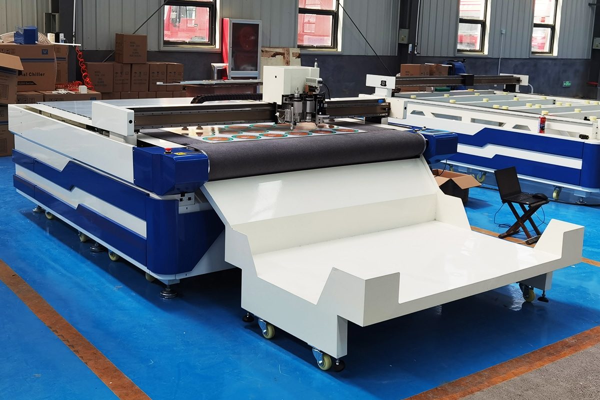
How To Reduce Dust Generated During Oscillating Knife Cutting?
Oscillating knife cutting machines are widely used to process flexible and semi-rigid materials such as foam, rubber, cardboard, corrugated board, fabric, leather, felt, gaskets, composites, and various packaging materials. Unlike laser cutting, which removes material through heat, oscillating knives use a rapidly moving blade to mechanically separate the material. This cold-cutting process avoids burning, melting, smoke, and heat-affected edges. However, it does not eliminate airborne contaminants. Depending on the material, blade condition, cutting parameters, and production environment, oscillating knife cutting can still generate dust, fibers, fine particles, crumbs, and debris.
Excessive dust can create several problems in a cutting workshop. Airborne particles may reduce indoor air quality, affect operator comfort, contaminate finished products, and accumulate on machine components. Dust deposited on guide rails, drive systems, vacuum tables, sensors, electrical components, and camera systems can also interfere with machine performance and increase maintenance requirements. In some applications, fine combustible dust may introduce additional fire or explosion risks if it is allowed to accumulate or become concentrated in extraction systems. Dust can also reduce the effectiveness of vacuum hold-down systems and make it more difficult to maintain a clean, efficient production area.
Reducing dust during oscillating knife cutting requires more than simply installing a dust collector. Effective control begins with understanding where the dust comes from and how material characteristics, blade selection, blade sharpness, oscillation frequency, cutting speed, cutting depth, tool pressure, and cutting strategy influence particle generation. Proper extraction, machine cleaning, material handling, preventive maintenance, and workplace ventilation are equally important.
This article explains the main causes of dust during oscillating knife cutting and explores practical methods for controlling it. By optimizing the cutting process and combining source reduction with effective dust collection and maintenance, manufacturers can achieve cleaner cuts, improve workplace conditions, protect equipment, and maintain more stable and efficient production.
Table of Contents
Understanding How Dust Is Generated During Oscillating Knife Cutting
Dust generated during oscillating knife cutting is the result of mechanical interaction between the blade and the material. Although oscillating knives do not burn or vaporize material like a laser, the rapid reciprocating motion of the blade can still produce fine particles, fibers, chips, and loose debris. The amount and type of dust depend on the material structure, blade geometry, oscillation frequency, cutting speed, penetration depth, number of passes, and condition of the cutting tool.
Understanding how dust forms is the first step toward reducing it. In many cases, excessive dust indicates that the material is being fractured, scraped, or abraded rather than being cleanly sliced. By identifying the dominant particle-generation mechanism, manufacturers can select more appropriate blades, optimize cutting parameters, improve extraction, and reduce unnecessary contamination around the cutting area.
How Oscillating Knife Cutting Works
Oscillating knife cutting machines use a sharp blade that moves rapidly up and down while the cutting head travels along a programmed path. The blade penetrates the workpiece and separates the material through mechanical shearing rather than heat. Depending on the tool design, oscillation may be driven electrically or pneumatically.
The rapid blade motion helps reduce cutting resistance, particularly when processing dense, thick, elastic, or layered materials. Instead of forcing a stationary knife continuously through the material, the oscillating movement repeatedly advances the cutting edge into the workpiece. This allows the blade to separate fibers, foam cells, rubber structures, paper layers, and other material components with relatively low cutting force.
When the blade is sharp and the parameters are properly matched to the material, the process can produce smooth edges with limited debris. However, if the blade is dull, the material is brittle, or cutting conditions are unsuitable, the repeated mechanical action can break small particles away from the cut edge. These particles become the dust and debris that must be controlled.
Cutting, Fracturing, Scraping, and Abrasion Mechanisms
Not all material removal during oscillating knife cutting occurs through clean slicing. Several mechanical mechanisms may occur simultaneously.
Cutting is the preferred mechanism. A sharp blade penetrates the material and creates a controlled separation along the cutting line. Clean cutting usually generates the least amount of dust because the material is divided rather than removed.
Fracturing occurs when brittle or rigid portions of the material crack ahead of or around the blade. Materials such as some foams, fiberboards, composites, and brittle plastics may produce small fragments when local stresses exceed their fracture strength. These fragments may range from visible chips to very fine dust.
Scraping occurs when the side or tip of the blade rubs against the cut surface instead of moving cleanly through it. Excessive blade deflection, incorrect tool alignment, excessive penetration, or a damaged blade can increase scraping. Small particles can then be shaved or scraped from the cutting edge.
Abrasion develops when repeated blade contact gradually wears the material surface. This is particularly important with fibrous, filled, layered, or abrasive materials. Instead of separating the material in a single clean action, the blade may grind against fibers, fillers, or coatings. This produces smaller particles that are more likely to become airborne.
Effective dust reduction therefore depends on maximizing clean cutting while minimizing fracture, scraping, and abrasion.
Difference Between Dust, Chips, Fibers, and Loose Debris
The material released during cutting is not always technically dust. Different particle types behave differently and require different control methods.
Dust consists of relatively small particles that can remain suspended in the air or be easily transported by machine airflow. Fine dust is particularly important because it can spread beyond the immediate cutting area, enter machine components, and affect workplace air quality.
Chips are larger fragments created when sections of material break away during cutting. They are usually heavier than dust and tend to remain near the cutting path or on the cutting table. Although chips are less likely to remain airborne, they can accumulate quickly and interfere with vacuum hold-down systems or subsequent cutting operations.
Fibers are elongated particles released when textiles, felt, insulation materials, fiber-reinforced products, or other fibrous materials are cut. Depending on their size and weight, fibers may remain on the table or become airborne.
Loose debris is a broader category that can include crumbs, flakes, fragments, coating residues, and pieces released from laminated materials. Understanding the type of waste being generated helps determine whether the priority should be local vacuum extraction, filtration, table cleaning, antistatic control, or process optimization.
Why Some Materials Generate More Dust Than Others
Material properties have a major influence on dust generation. Soft and homogeneous materials that can be sliced cleanly generally produce less dust than brittle, porous, fibrous, abrasive, or composite materials.
Brittle materials tend to fracture around the cutting edge, creating small particles. Open-cell and closed-cell foams may produce crumbs or fine fragments when the cell walls rupture. Paperboard, corrugated materials, and fiber-based sheets can release cellulose particles and fibers, particularly if the blade drags across the surface.
Composite materials may generate significant dust because they contain multiple components with different mechanical properties. A blade may cut the softer matrix while simultaneously fracturing or abrading harder fillers and reinforcement materials. Laminated products can also release fragments when individual layers respond differently to blade movement.
Material density, hardness, elasticity, fiber orientation, moisture content, surface coatings, and internal fillers all influence how easily the workpiece can be cut. Two materials that appear similar may therefore generate very different quantities and types of dust.
How Blade Oscillation Produces Fine Particles
Blade oscillation reduces cutting resistance, but the rapid reciprocating movement can also contribute to fine particle formation. Each oscillation cycle creates repeated contact between the cutting edge and the material. At high frequencies, thousands of cutting interactions may occur over a short section of the cutting path.
Ideally, each movement contributes to clean separation. However, when the blade is dull, unsuitable for the material, or moving under excessive resistance, the repeated motion can act like a miniature sawing or grinding process. Instead of producing one smooth cut surface, the blade repeatedly scrapes the same region.
Higher oscillation frequency does not automatically mean more dust. For difficult materials, sufficient oscillation can actually improve cutting quality and reduce tearing. The problem occurs when oscillation frequency, amplitude, cutting speed, and blade geometry are poorly matched. Excessive mechanical interaction can then increase abrasion and release smaller particles.
Blade condition is therefore critical. A sharp blade requires less force and produces cleaner separation, while a worn edge tends to crush, rub, and abrade the material.
How Cutting Speed Influences Particle Generation
Cutting speed determines how long the blade interacts with a particular section of material. Both excessively low and excessively high speeds can increase particle generation.
When cutting too slowly, the oscillating blade makes more repeated movements within the same section of the cut. This can increase rubbing and abrasion, particularly with fibrous or brittle materials. Instead of passing efficiently through the workpiece, the blade may repeatedly scrape the cut surface and produce additional fine particles.
When cutting too quickly, the blade may not have enough time to separate the material cleanly. Cutting resistance increases, which may cause blade deflection, tearing, cracking, or incomplete separation. The result can be rough edges and larger quantities of fragments or fibers.
The best cutting speed balances productivity with clean material separation. It should be matched with blade type, oscillation frequency, material thickness, density, and geometry. Parameter testing is often necessary because the speed that minimizes dust may differ significantly between foam, rubber, cardboard, textiles, and composite sheets.
The Effect of Blade Penetration and Cutting Depth
Blade penetration should be sufficient to cut completely through the material without creating excessive contact with the cutting mat, conveyor belt, or supporting surface.
Insufficient penetration may leave sections partially connected. The machine may then tear the remaining material during part removal or require another cutting pass. Both conditions can increase loose fibers and debris.
Excessive penetration creates a different problem. When the blade extends too far beneath the workpiece, its tip may continuously contact the cutting mat or conveyor surface. This increases blade wear and can cause the tool to drag rather than cut smoothly. Worn blade tips and additional friction can indirectly increase dust generation.
Too much penetration can also increase blade deflection, particularly when processing thick or dense materials. The sides of the blade may rub against the cut walls, creating scraping and abrasion.
For consistent dust control, cutting depth should be calibrated so that the blade completely separates the material with only the minimum necessary penetration beyond the bottom surface.
How Repeated Passes Increase Dust Formation
Some thick or difficult materials require multiple passes to achieve complete separation. Although multi-pass cutting may be necessary, every additional pass increases mechanical interaction between the blade and the cut surface.
During the first pass, the blade forms a cutting path through the material. On subsequent passes, the blade may contact surfaces that have already been partially cut. Instead of encountering solid material, it can rub against loose fibers, fractured edges, or narrow cut walls. This increases the possibility of abrasion and particle formation.
Repeated passes may be particularly dusty when the cutting path does not align perfectly between passes. Even small differences in blade position can cause the tool to shave material from the sides of the existing cut.
Whenever possible, cutting parameters should be optimized to achieve complete separation with the minimum number of passes. When multiple passes are necessary, penetration depth, speed, tool alignment, and blade condition should be carefully controlled to prevent unnecessary edge abrasion.
Static Electricity and Airflow as Secondary Dust-Spreading Mechanisms
Static electricity does not normally create dust directly, but it can significantly influence where dust travels and accumulates. Friction between the blade, material, conveyor surface, and surrounding components can generate electrostatic charges, particularly when cutting synthetic plastics, foams, films, textiles, or other insulating materials.
Charged particles may adhere to machine covers, sensors, camera lenses, cutting heads, cables, and finished parts. They can also remain suspended or move unpredictably when exposed to nearby airflow. This makes cleanup more difficult and may give the impression that the cutting process is generating more dust than it actually is.
Airflow is another important secondary mechanism. Vacuum hold-down systems, cooling air, pneumatic tools, extraction systems, open doors, ventilation fans, and machine movement can all transport particles away from the cutting point. An improperly positioned extraction inlet may even cause dust to spread across the table before it is captured.
Effective dust control must therefore address both particle generation and particle movement. Proper grounding, antistatic measures, controlled airflow, and extraction located close to the cutting zone can prevent fine particles from spreading throughout the machine and workshop.
Dust generation during oscillating knife cutting is primarily a mechanical phenomenon. A properly selected, sharp blade should separate material through clean cutting, but fracturing, scraping, abrasion, excessive oscillation, poor speed selection, incorrect penetration, and repeated passes can all create additional particles. The characteristics of the workpiece also determine whether the process produces fine dust, chips, fibers, crumbs, or larger fragments.
Material structure is especially important. Brittle, porous, fibrous, filled, abrasive, and laminated materials generally have a greater tendency to release particles than soft, homogeneous materials that can be cleanly sliced. Cutting parameters then determine how strongly these material characteristics influence actual dust production.
Secondary factors such as static electricity and uncontrolled airflow may not generate particles themselves, but they can spread contamination far beyond the cutting line and make dust harder to collect.
For this reason, effective dust reduction should begin at the cutting point rather than relying entirely on downstream filtration. Selecting the correct blade, maintaining blade sharpness, optimizing oscillation and cutting speed, controlling penetration depth, minimizing unnecessary passes, and managing airflow can substantially reduce particle generation. Once the mechanisms responsible for dust are understood, manufacturers can combine process optimization with extraction and housekeeping measures to create a cleaner, more reliable, and more efficient oscillating knife cutting operation.
Materials Most Likely to Generate Dust
The amount of dust produced during oscillating knife cutting depends heavily on the material being processed. Some materials separate cleanly under a sharp blade and generate only small amounts of loose debris, while others fracture, crumble, shed fibers, or release fine particles along the cutting path. Material composition, density, hardness, brittleness, porosity, fiber orientation, coatings, fillers, and laminated structures all influence how much contamination is created.
Understanding which materials are naturally more prone to dust generation makes it easier to select suitable blades, cutting speeds, oscillation settings, extraction systems, and maintenance procedures. It is also important to distinguish between visible debris and fine airborne particles. A material that produces relatively little large waste may still release fine fibers or microscopic particles that require effective local extraction and filtration.
Foam and Cellular Materials
Foam is one of the most common materials processed with oscillating knife cutting machines, but dust generation varies greatly among different foam types. Flexible polyurethane foam, polyethylene foam, EVA foam, PVC foam, and other cellular materials have different cell structures, densities, and mechanical properties.
Soft, flexible foams often cut cleanly when a sharp blade and suitable parameters are used. However, rigid or brittle foams may fracture around the cutting edge, producing crumbs and fine particles. Materials with large open cells may tear rather than slice cleanly, while dense closed-cell foams can create small fragments if the blade compresses the material excessively before separation.
A dull blade, excessive oscillation, incorrect cutting speed, or repeated passes can significantly increase foam debris. Because foam particles are often lightweight, they can easily become airborne or be transported across the cutting table by vacuum airflow. Local dust extraction and frequent removal of loose particles are therefore important when processing foam continuously.
Rubber and Elastomeric Materials
Rubber and elastomeric materials generally produce less fine dust than brittle materials because their flexibility allows them to deform around the blade. However, dense, reinforced, aged, or highly filled rubber can still generate significant particles.
Natural rubber, silicone rubber, neoprene, EPDM, nitrile rubber, and similar materials may create fine shavings or crumbs when the blade rubs against the cut surface. Hard rubber and gasket-grade compounds containing fillers such as carbon black, silica, minerals, or fibers can produce more particulate contamination.
Elastic recovery can also cause the cut walls to press against the blade, increasing friction and abrasion. If cutting speed is too high or the blade is not sufficiently sharp, the material may stretch, tear, or drag instead of separating cleanly. Correct blade geometry and controlled penetration are therefore especially important for minimizing debris from elastomeric materials.
Fiberboard and Wood-Based Sheet Materials
Fiberboard and other wood-based sheets have a relatively high potential for dust generation because they are made from compressed fibers, particles, or wood components bonded together with resin.
Low-density fiberboard, medium-density fiberboard, hardboard, wood-fiber sheets, and similar products can release fine cellulose particles when cut. The blade must pass through a structure consisting of numerous fibers and bonding points. Instead of separating along a single continuous plane, individual fibers can break, pull out, or become abraded.
Higher-density boards may create finer particles because of their compact structure, while loosely bonded sheets may produce larger fragments and fibers. Resin content, surface coatings, and moisture level also influence the behavior.
Oscillating knives are generally better suited to relatively thin or softer fiber-based sheets than thick, hard wood panels. When these materials are suitable for knife cutting, sharp blades, controlled speeds, effective extraction, and frequent table cleaning are essential for managing dust.
Cardboard, Paperboard, and Honeycomb Materials
Cardboard and paper-based materials can generate substantial amounts of lightweight fibers and paper dust, especially during high-volume production.
Corrugated cardboard contains multiple paper layers and fluted structures. As the blade passes through these layers, individual cellulose fibers may break away from the edges. Dull blades can crush the corrugated structure before cutting it, increasing dust and producing ragged edges.
Solid paperboard generally produces less loose debris when cut with a sharp blade, but very dense or recycled boards may contain short fibers and fillers that separate more easily. Recycled paper products may therefore create more dust than high-quality board made from longer fibers.
Honeycomb board can be particularly challenging because its internal cellular structure contains numerous thin walls. Cutting through these walls can create fragments and loose fibers. Because paper dust is lightweight and can spread easily, extraction near the cutting head and regular cleaning of the vacuum table are important.
Fiberglass and Composite Materials
Fiberglass and composite materials can generate fine and potentially irritating particles when mechanically cut. Their structure often combines reinforcement fibers with a polymer matrix, producing different cutting behaviors within the same material.
When a blade passes through fiberglass-reinforced sheets, it must simultaneously separate the matrix and the reinforcement fibers. Some fibers may be sliced cleanly, while others may break, pull out, or splinter. Repeated contact can produce very small fiber fragments.
Composite materials containing multiple reinforcement layers, fillers, coatings, or cores may generate a mixture of dust, fibers, and flakes. Blade wear can also be accelerated because glass fibers are abrasive.
These materials require particularly careful dust control. Appropriate local extraction, filtration, machine cleaning, and personal protective measures should be selected according to the material manufacturer’s safety information and the specific composition being processed.
Carbon-Fiber-Based Materials
Carbon-fiber-based materials require special attention because cutting can release conductive carbon fibers and fine particles. The amount of dust depends on whether the material is dry fabric, prepreg, flexible composite sheet, or a cured laminate.
Dry carbon-fiber fabrics may shed loose filaments along cut edges, especially if the weave is disturbed during cutting. Prepreg materials may produce fewer airborne fibers because the reinforcement is held together by resin, but edge fragments can still occur.
Cured carbon-fiber composites are much harder and more abrasive. Depending on thickness and construction, they may not always be ideal for oscillating knife cutting. When mechanical cutting is suitable, the blade can produce fine carbon and resin particles through fracture and abrasion.
Conductive carbon particles can create additional equipment concerns if they enter electrical components. Effective extraction, filtration, grounding, and frequent cleaning are therefore especially important when processing carbon-fiber-based materials.
Insulation Materials
Insulation products can generate large quantities of lightweight fibers and particulate matter because many are intentionally manufactured with porous, fibrous, or cellular structures.
Examples include mineral-fiber insulation, polyester insulation, felt insulation, foam insulation, acoustic panels, and layered thermal insulation products. During cutting, fibers may be severed, pulled from the surrounding structure, or loosened by vibration.
Low-density insulation materials can be particularly difficult to control because their particles are extremely light and can be moved easily by air currents. Even relatively gentle airflow from extraction systems or vacuum tables can spread fibers across the work area if collection points are poorly positioned.
Blade sharpness is critical because a dull blade tends to compress and tear the material. Proper local extraction should capture fibers as close as possible to the cutting zone before they spread throughout the machine.
Textiles and Technical Fabrics
Most conventional textiles generate relatively little mineral-like dust, but they can release fibers, lint, and microscopic fragments during cutting.
Natural fabrics such as cotton may shed short cellulose fibers, while synthetic textiles can release fine polymer filaments. Technical fabrics containing glass, aramid, polyester, carbon fibers, or multiple reinforcement layers may generate more significant contamination.
Fabric construction also matters. Loosely woven materials may shed more fibers than tightly woven fabrics. Nonwoven materials may release fibers depending on how strongly the structure is mechanically or chemically bonded.
A sharp blade usually produces a clean edge and reduces fiber pullout. If the blade becomes dull, however, it can drag fibers from the fabric rather than cutting them cleanly. Proper material hold-down is equally important because movement or wrinkling can increase tearing and loose fibers.
Gasket and Sealing Materials
Gasket and sealing materials cover a wide range of compositions, including rubber, cork, fiber-reinforced sheets, graphite, compressed fiber, foam, and multilayer structures. As a result, their dust behavior varies significantly.
Soft rubber or foam gaskets may create relatively little fine dust, whereas compressed fiber sheets can produce substantially more particulate matter. Cork materials may release crumbs and small granules as their cellular structure breaks around the cutting line.
Graphite-containing gasket materials can generate fine dark particles that spread easily across machine surfaces. Fiber-reinforced sealing products may release both dust and short fibers.
Because gasket materials frequently contain fillers and reinforcement components, manufacturers should evaluate each material individually and consult its safety documentation before determining the required extraction and filtration system.
Plastics and Polymer Sheets
Many flexible plastic sheets can be cut with minimal dust when the blade slices cleanly through the material. However, harder, brittle, filled, or foamed polymers may produce chips and fine particles.
Polypropylene, polyethylene, PVC, PET, EVA, and other thermoplastics behave differently depending on hardness, thickness, temperature, and formulation. Flexible polymer sheets tend to deform and separate cleanly, while rigid sheets may crack or chip around the blade.
Filled polymers can create more dust because mineral fillers, glass fibers, or other additives may fracture during cutting. Foamed plastic sheets may also produce crumbs because of their cellular structure.
Static electricity is often important when cutting plastics. Fine polymer particles can become electrostatically charged and adhere to the machine, workpiece, cutting head, or surrounding surfaces. Grounding and antistatic measures can therefore complement mechanical dust extraction.
Leather and Synthetic Leather
Natural leather generally generates relatively little airborne dust when cut with sharp oscillating knives, but it can release small fibers and fragments from the cut edge. The amount depends on thickness, tanning method, surface treatment, and internal fiber structure.
Thick or dense leather may require greater cutting force, increasing the risk of blade drag and edge abrasion. Suede and other fibrous surfaces may release more loose fibers than smooth finished leather.
Synthetic leather often consists of a polymer surface layer bonded to a woven, knitted, or nonwoven backing. Cutting therefore involves several different materials simultaneously. The surface coating may create small polymer fragments while the backing releases fibers.
A suitable blade, stable material hold-down, and correct cutting speed help reduce edge fraying and particle formation. Extraction requirements should be based on the particular leather or synthetic material being processed.
Materials With Coatings, Adhesives, or Laminated Layers
Coated, adhesive-backed, and laminated materials can produce more complex debris than single-layer materials because the blade encounters multiple structures during one cut.
A coated sheet may consist of a flexible substrate covered with paint, polymer film, foil, protective coating, or decorative layer. If the coating is brittle, it can crack or flake around the cutting edge even when the base material cuts cleanly.
Pressure-sensitive adhesives may accumulate on the blade, causing increased friction and material drag. Once the cutting edge becomes contaminated, the blade may begin scraping instead of slicing, increasing debris production.
Laminated materials can also delaminate if the layers have significantly different stiffness or adhesion. Small flakes, fibers, and adhesive residues may then be released during cutting.
Regular blade inspection and cleaning are particularly important with adhesive-containing materials. Cutting parameters may also need to be adjusted to avoid excessive compression, friction, and repeated passes.
How Material Density, Brittleness, and Fiber Structure Affect Dust Production
Material density strongly influences the forces required for cutting. Very soft, low-density materials may compress under the blade and then tear if they are not adequately supported. Dense materials require greater cutting force and can cause more friction against the blade. If cutting resistance becomes excessive, scraping and abrasion can increase.
Brittleness has an even more direct relationship with particle generation. Ductile and elastic materials tend to deform before separating, while brittle materials fracture when stress exceeds their strength. These fractures can extend beyond the immediate blade path and release numerous small particles. Rigid foams, hard composites, brittle polymer sheets, and some fiberboards therefore tend to generate more dust than flexible materials.
Fiber structure determines both the quantity and form of debris. Long, continuous fibers may produce strands or loose filaments, while short fibers can form fine dust more easily. Fiber orientation also affects cutting resistance. Cutting across strong fibers may require more force and produce more fragments than cutting parallel to them.
Bonding strength between fibers is equally important. Weakly bonded materials release fibers easily, while strongly bonded structures can require greater force and potentially create smaller fractured particles. For composites, the relationship between the reinforcement and surrounding matrix further determines whether fibers are cleanly cut, pulled out, or broken.
Dust generation during oscillating knife cutting varies significantly from one material to another. Foam, fiberboard, cardboard, fiberglass composites, carbon-fiber materials, insulation products, technical fabrics, gasket sheets, plastics, leather, and laminated materials can all generate particles, but the size, quantity, and behavior of those particles depend on their internal structure.
Brittle materials often create dust through fracture, while fibrous materials release loose fibers through cutting and pullout. Cellular materials may produce crumbs, and composites can generate a mixture of matrix dust and reinforcement fibers. Filled, coated, adhesive-backed, and laminated materials add further complexity because each constituent may respond differently to the blade.
Material density, brittleness, fiber orientation, bonding strength, porosity, and filler content should therefore be considered when developing a dust-control strategy. Blade selection and cutting parameters should be matched to these characteristics rather than applied uniformly to all materials.
Reducing dust begins with understanding the behavior of the workpiece itself. By identifying materials with a high tendency to crumble, fracture, shed fibers, or generate fine particles, operators can select sharper and more appropriate blades, optimize speed and oscillation, minimize repeated passes, improve local extraction, and establish suitable cleaning procedures. This material-specific approach is essential for maintaining cleaner cutting conditions, consistent edge quality, reliable machine operation, and a safer production environment.
Select the Correct Cutting Tool
Selecting the correct cutting tool is one of the most effective ways to reduce dust during oscillating knife cutting. Dust is often treated as a problem that must be solved with extraction equipment, filtration, or cleaning, but a large portion of particle generation can be prevented before it occurs. If the tool is properly matched to the material, it can separate the workpiece through clean shearing rather than excessive rubbing, tearing, crushing, or abrasion.
Different materials respond differently to cutting forces. Flexible foam may require rapid oscillation to reduce compression, while thin cardboard may cut more cleanly with a drag knife. Technical fabrics may benefit from a rotary cutting tool, while corrugated board may require a combination of cutting and creasing tools. Choosing an unsuitable tool can increase cutting resistance, force operators to use slower speeds or repeated passes, and create more dust, fibers, and loose debris.
For this reason, tool selection should be considered the first stage of dust prevention. The goal is to select the cutting mechanism that achieves complete separation with the least unnecessary mechanical disturbance to the material.
Match the Tool Type to the Material
The cutting tool should always be selected according to the mechanical characteristics of the material. Thickness, density, hardness, elasticity, fiber structure, brittleness, and layering all influence which tool will create the cleanest cut.
Soft, thick, or compressible materials such as foam, rubber, felt, and some gasket materials often benefit from oscillating knives because the reciprocating movement reduces the continuous cutting force required to penetrate the material. A conventional stationary blade may push or deform these materials before cutting them, resulting in tearing or edge distortion.
Thin, relatively easy-to-cut sheets such as vinyl, paper, some films, and lightweight cardboard may not require oscillation. A drag knife can sometimes make a cleaner cut with less mechanical disturbance.
Fibrous textiles may be better suited to rotary cutting in certain applications because the rolling blade can separate fibers continuously without repeatedly moving up and down through them. Corrugated packaging products may require both cutting and creasing rather than cutting every feature completely through the material.
The best tool is therefore not necessarily the most powerful or aggressive option. It is the tool that produces the required geometry with the minimum cutting resistance and minimum disturbance to the material structure.
Oscillating Knife Versus Drag Knife
Oscillating knives and drag knives operate differently and should be selected according to material thickness and cutting resistance.
Oscillating knives move rapidly up and down while traveling through the programmed cutting path. This motion allows the cutting edge to repeatedly penetrate and separate the material, reducing resistance when processing thick, dense, flexible, or compressible products. It is commonly used for foam, rubber, corrugated board, felt, gasket material, and other relatively difficult sheets.
A drag knife, by contrast, does not oscillate. The blade is pulled continuously through the workpiece as the cutting head moves. This simpler motion can be effective for thin and relatively soft materials that do not require high cutting force.
From a dust-control perspective, unnecessary oscillation should be avoided. If a thin material can be cut cleanly with a drag knife, introducing rapid reciprocating motion may increase rubbing along the cut walls and create additional fine particles or fibers.
However, using a drag knife on material that is too thick or resistant can create the opposite problem. Excessive drag force can tear fibers, compress foam, distort rubber, or cause irregular edges. In such cases, oscillating knives may actually generate less dust because it reduces the mechanical force needed for separation.
Tool selection should therefore be based on actual cutting behavior rather than assuming that one knife type always produces less dust.
Electric Oscillating Tool Versus Pneumatic Oscillating Tool
Oscillating knife cutting systems may use electric or pneumatic drive mechanisms. Both can provide effective cutting, but their performance characteristics make them suitable for different applications.
Electric oscillating tools typically provide precise control over blade motion and are widely used for foam, rubber, cardboard, leather, textiles, and gasket materials. Depending on the machine design, oscillation frequency and cutting parameters can be adjusted to suit different materials. Controlled blade movement can help maintain consistent cut quality while limiting unnecessary abrasion.
Pneumatic oscillating tools use compressed air to generate powerful reciprocating movement. They are often useful for thicker, denser, or more resistant materials where greater cutting force is required. Materials such as heavy rubber, dense foam, thick felt, and some industrial sealing products may benefit from pneumatic oscillation.
For dust reduction, more cutting power should not automatically be considered better. A very aggressive pneumatic tool used on a lightweight or brittle material may produce excessive vibration, edge damage, and particle release. Conversely, electric oscillating tools with insufficient cutting capability may require slow feed rates or repeated passes through dense material, which can also increase dust.
The appropriate tool should provide enough cutting force to achieve clean separation without unnecessary mechanical aggression.
When a Rotary Tool May Produce Less Loose Fiber
Rotary cutting tools can sometimes reduce loose fiber generation when processing textiles and other fibrous materials. Instead of using a reciprocating blade, the rotary tool employs a circular cutting wheel that rolls through the material.
This continuous rolling action can be advantageous for fabrics because it reduces the repeated vertical impact associated with oscillating Knife cutting. Individual fibers may be sliced continuously rather than being repeatedly pushed, lifted, or pulled by a reciprocating blade.
Rotary tools can be particularly useful for woven fabrics, nonwoven materials, technical textiles, thin felt, and certain fiber-reinforced flexible products. When properly applied, they can reduce edge fraying, loose threads, and airborne lint.
However, rotary cutting is not suitable for every material. Thick foam, dense rubber, or rigid sheets may require the greater penetration capability of oscillating knives. Rotary blades can also become less effective if they are dull or unable to maintain adequate pressure through multiple layers.
The decision should therefore be based on fiber behavior and cutting quality. If an oscillating blade causes excessive fiber pullout or fuzzing, testing a rotary cutting tool may provide cleaner edges and reduce loose fiber contamination.
When a V-Cut or Creasing Tool Can Replace Material Removal
Not every production feature requires complete cutting through the material. In packaging, display, insulation, foam fabrication, and similar applications, folds, bends, or angled joints may sometimes be created using V-cutting or creasing tools rather than removing material with more aggressive cutting methods.
A creasing tool compresses or deforms the material along a programmed line so that it can be folded accurately. Because it does not normally remove material, it can generate significantly less debris than cutting a groove or channel.
This is particularly useful for corrugated cardboard, paperboard, and packaging materials. Instead of cutting several parallel lines or partially removing layers to produce a fold, a creasing wheel can create the required folding line with minimal particle generation.
V-cut tools are used to create angled grooves, often in foam, honeycomb panels, cardboard, and similar materials. Although some V-cut operations still remove or separate material, they can produce cleaner geometry than repeatedly cutting an angled feature with a standard knife.
Whenever the final product only requires controlled folding, bending, or shaping rather than complete material separation, selecting a dedicated creasing or V-cut tool can reduce unnecessary cutting and therefore reduce dust.
Avoid Using Abrasive Tools When a Knife Can Perform the Cut
Abrasive cutting tools remove material through grinding, sanding, or high-friction contact. This mechanism inherently generates more particulate matter than clean knife cutting.
If a suitable oscillating, drag, or rotary knife can achieve the required cut, using an abrasive tool unnecessarily increases dust production. Abrasive wheels and similar tools break the material into small particles as part of their normal cutting mechanism. Even with effective extraction, more fine dust is produced at the source.
Knife cutting, by comparison, is primarily a material-separation process. Ideally, the blade divides the workpiece along a narrow cut line without removing a significant volume of material. This produces little or no kerf waste and generally creates fewer airborne particles.
This advantage is especially important when processing foam, rubber, cardboard, textiles, leather, and other nonmetallic materials that can be separated mechanically with a blade.
Of course, certain hard, highly abrasive, or rigid materials may not be suitable for knife cutting. But whenever both methods are technically feasible, the lower-particle cutting process should be considered first.
Use Dedicated Tools for Different Material Families
Using one cutting tool for every material may appear convenient, but it often reduces cutting quality and increases dust production. Different material families place different demands on blade geometry, thickness, length, stiffness, and cutting mechanism.
A blade optimized for soft foam may not perform well on dense rubber. A knife suitable for cardboard may quickly become dull when used on abrasive fiberglass-containing materials. A blade intended for flexible textiles may not provide sufficient stiffness for thick gasket sheets.
Frequent switching between significantly different materials can also accelerate blade contamination and wear. Adhesive-backed products can leave residue on the cutting edge, which may then interfere with clean cutting when the same blade is used on foam, paperboard, or textiles.
Where production volume justifies it, dedicated blades or tool sets should be assigned to specific material families. For example, separate tools may be maintained for foam, rubber, cardboard, textiles, composites, and adhesive-backed products.
This approach makes tool condition easier to monitor, reduces cross-contamination, and allows cutting parameters to be standardized for each material category. It also makes it easier to recognize when a blade has reached the end of its useful cutting life.
Tool Selection as the First Stage of Dust Prevention
Dust-control systems should begin with preventing particles from being generated rather than relying only on capturing them after they enter the air.
Correct tool selection reduces dust by improving the fundamental cutting mechanism. A properly matched tool separates material cleanly, requires less force, produces smoother edges, and minimizes scraping, crushing, fracturing, and fiber pullout. It can also reduce the need for slow cutting speeds and repeated passes, both of which may increase particle generation.
Before adjusting extraction airflow or installing larger filtration equipment, operators should therefore evaluate whether the current cutting tool is appropriate for the material. Questions should include whether oscillation is necessary, whether a drag or rotary knife would provide cleaner separation, whether a creasing tool could replace a cut, and whether the blade geometry is appropriate for the material thickness and structure.
Cut tests provide a practical way to compare alternatives. Operators should examine edge quality, particle generation, cutting force, blade wear, required number of passes, and overall productivity. The tool producing the cleanest complete separation with the least mechanical disturbance will generally provide the best starting point for dust reduction.
Selecting the correct cutting tool is a fundamental part of reducing dust during oscillating knife cutting. Different materials require different cutting mechanisms, and using an inappropriate tool can increase friction, tearing, fracture, abrasion, loose fibers, and repeated cutting.
Oscillating knives are well suited to many thick, dense, flexible, and compressible materials, while drag knives may provide cleaner results on thinner sheets that do not require reciprocating motion. Electric and pneumatic oscillating tools should be selected according to the cutting resistance of the material rather than simply choosing the most powerful option. For some textiles and fibrous products, rotary cutting can reduce fiber pullout and loose lint. In packaging applications, V-cutting and creasing tools can sometimes create the required geometry without unnecessary material removal.
Manufacturers should also avoid abrasive cutting methods when a knife can perform the same task cleanly and should consider dedicated tools for different material families to maintain blade condition and consistent performance.
Most importantly, dust prevention should begin at the cutting point. Extraction and filtration remain essential for materials that naturally generate particles, but they cannot fully compensate for poor tool selection. By choosing a cutting mechanism that produces clean separation with minimal mechanical disturbance, manufacturers can reduce dust at its source, improve edge quality, extend tool life, simplify cleaning, and create a more efficient cutting process.
Optimize Blade Selection to Reduce Dust
Blade selection has a direct influence on how much dust, fiber debris, and loose particulate matter is generated during oscillating knife cutting. Even when the machine, cutting speed, oscillation frequency, and extraction system are properly configured, an unsuitable blade can cause unnecessary friction, tearing, scraping, crushing, or abrasion. These effects increase particle formation and often reduce edge quality at the same time.
The ideal blade should penetrate the material easily, remain stable during directional changes, and separate the workpiece with the minimum possible cutting resistance. Its geometry, length, thickness, tip shape, edge configuration, material, and sharpness should all be matched to the workpiece. A blade that performs well on soft foam may be unsuitable for dense rubber, corrugated board, technical textiles, or fiber-reinforced gasket sheets.
Effective dust reduction therefore requires more than simply replacing blades when they break. Manufacturers should establish material-specific blade selections, monitor cutting quality, identify signs of wear, and replace blades before dullness begins to create excessive debris. Optimizing blade selection can reduce dust at its source while also improving cutting accuracy, productivity, and tool life.
Choose the Correct Blade Geometry
Blade geometry determines how the cutting force is transferred into the material. An appropriate geometry creates clean separation, while an unsuitable geometry may compress, drag, fracture, or abrade the workpiece.
The correct blade depends on material thickness, density, hardness, elasticity, fiber orientation, and internal structure. Soft foam usually requires different blade characteristics from dense gasket material, while thin textiles may respond differently from corrugated cardboard or laminated sheets.
A narrow, sharp blade can reduce cutting resistance in many applications, but insufficient stiffness may cause blade deflection in thick or dense materials. Conversely, a thick, rigid blade may remain stable but generate excessive friction along the cut walls.
Blade geometry should therefore be selected as a complete system rather than by focusing on one feature alone. Edge style, tip angle, blade thickness, exposed length, and cutting depth should work together to achieve clean separation with minimal material disturbance.
Straight Blades
Straight blades are among the most widely used blades for oscillating knife cutting. Their simple cutting edge provides predictable behavior and makes them suitable for many foams, rubber sheets, cardboard products, gasket materials, leather, and other flexible or semi-rigid materials.
A sharp straight blade can produce very clean cuts because the edge passes continuously through the workpiece without excessive tearing. For homogeneous materials, this generally results in relatively low dust production.
Straight blades are especially effective when the material can be separated primarily through slicing. However, the blade must have sufficient stiffness for the required cutting depth. If a long, thin straight blade bends while cutting thick or dense material, the sides of the blade may rub against the cut walls. This increases friction and can produce additional particles.
For low-dust cutting, straight blades should be selected with an appropriate combination of width, thickness, length, and edge angle.
Pointed Blades
Pointed blades have a narrow tip that helps initiate penetration into the material. They are useful when the cutting process requires frequent plunging, tight contours, small internal features, or precise starting points.
Because the pointed tip concentrates cutting force over a small area, it can enter many materials with less initial resistance. This reduces compression around the entry point and may help prevent tearing or cracking.
However, a very sharp or narrow point can be more vulnerable to wear, bending, or breakage, particularly when cutting dense or abrasive materials. Once the tip becomes damaged, it may scrape rather than slice the workpiece.
Pointed blades should therefore be used where their penetration characteristics provide a real advantage. For materials that fracture easily, excessive point pressure should be avoided because concentrated stress can create chips or cracks around the cutting line.
Flat-Ended Blades
Flat-ended blades can be useful in applications where controlled penetration and stable vertical cutting are more important than sharp point entry. Their geometry can provide greater tip strength and resistance to breakage than extremely pointed blades.
They may be suitable for certain foams, rubber products, gasket materials, and other sheets where the blade enters from an existing edge or where plunge cutting is limited.
The reduced point concentration can also help prevent the blade from excessively digging into soft materials or the cutting mat. However, flat-ended blades generally require more force to initiate penetration than pointed designs.
If the tool must frequently plunge into dense material, excessive entry force can increase deformation or local particle generation. For this reason, flat-ended blades should be selected when their strength and stability outweigh the need for low-force point penetration.
Serrated Blades
Serrated blades contain multiple small teeth along the cutting edge. These teeth concentrate force at several points and can help the blade penetrate materials that are difficult to slice with a smooth edge.
They may be useful for certain thick, fibrous, layered, or resistant materials. The serrations can reduce overall cutting force by creating a localized sawing action.
However, this same action can increase dust and fiber debris. Each tooth repeatedly engages the material, potentially tearing fibers or removing small particles rather than producing one continuous smooth separation.
Serrated blades should therefore not be selected automatically for difficult materials. If a smooth blade can achieve complete separation without excessive force, it will often produce less dust. Serrated blades are most appropriate when they significantly improve cutting performance and reduce tearing compared with other blade options.
Their condition should also be monitored carefully because worn serrations can increase abrasion and produce rougher edges.
Single-Edge Versus Double-Edge Blades
Single-edge and double-edge blades differ in how their cutting geometry interacts with the workpiece.
A single-edge blade is sharpened primarily from one side. Depending on its orientation, it can provide controlled cutting behavior and may help manage the direction of material displacement. It is often useful when maintaining a predictable cut edge is important.
A double-edge blade has symmetrical sharpening on both sides of the cutting edge. This geometry can balance cutting forces and may improve straight tracking through certain materials.
From a dust-control perspective, neither design is universally better. The important consideration is which configuration produces the lowest resistance and least side friction for the specific material.
An incorrectly selected edge geometry can cause the blade to push material sideways, create excessive compression, or rub against one wall of the cut. This is especially important in thick materials where the blade remains in contact with the cut surfaces for a longer distance.
Testing both configurations on demanding materials can help identify which one provides cleaner edges and lower particle generation.
Blade Thickness and Cutting Resistance
Blade thickness affects both cutting resistance and mechanical stability. Thin blades generally displace less material as they pass through the workpiece, reducing friction along the sides of the cut. This can be advantageous for reducing dust.
However, very thin blades have lower stiffness and may bend when cutting dense, thick, or highly resistant materials. Blade deflection can cause the sides of the blade to scrape against the material, producing additional particles and reducing dimensional accuracy.
Thicker blades provide greater rigidity and may remain more stable in deep cuts. However, they also create greater displacement and surface contact, which increases cutting resistance.
The optimal blade thickness is therefore the minimum thickness that provides sufficient stiffness for stable cutting. Choosing an unnecessarily thick blade may increase friction without providing any practical benefit, while choosing one that is too thin may create dust through deflection and rubbing.
Blade Length and Material Thickness
Blade length should be matched closely to the thickness of the material being processed. The blade must extend far enough to penetrate completely through the workpiece, but excessive unsupported length should be avoided.
A blade that is too short may fail to complete the cut, leaving fibers or sections of material attached. Operators may then need additional passes, which increases mechanical interaction and dust generation.
An unnecessarily long blade has greater potential to bend or vibrate under cutting load. This can result in inaccurate cuts and increased contact between the blade sides and the cut walls.
For thick materials, the blade must provide sufficient cutting depth while maintaining adequate stiffness. Blade length, thickness, and geometry should therefore be evaluated together.
Ideally, the exposed blade length should be only slightly greater than what is required to cut through the material and achieve the specified penetration into the supporting surface.
Blade Tip Angle
The blade tip angle influences penetration force, cutting resistance, edge durability, and the way stress is distributed through the material.
A smaller, sharper angle generally penetrates more easily and requires less force. This can reduce compression and tearing in soft or flexible materials. It may also reduce particle generation because the blade separates the material before significant deformation occurs.
However, very acute angles create thinner and more fragile cutting edges. They can wear rapidly when processing abrasive, dense, or fiber-reinforced materials.
A larger tip angle produces a stronger edge that can withstand higher forces, but it may require greater pressure to penetrate the material. Excessive force can increase compression, cracking, or friction.
The optimal blade angle balances sharpness with durability. Soft materials can often benefit from sharper geometries, while dense or abrasive materials may require stronger blade angles that maintain effective cutting performance over longer production runs.
Blade Sharpness and Particle Formation
Blade sharpness is one of the most important factors influencing dust generation. A sharp cutting edge concentrates force efficiently and separates the material with minimal resistance.
When a blade is sharp, fibers are sliced rather than pulled, cellular structures are cut rather than crushed, and polymer or rubber sheets are separated with less deformation. This reduces the mechanical energy transferred into surrounding material and therefore reduces the formation of unwanted particles.
Sharp blades also allow higher and more stable cutting speeds in many applications. This limits the amount of time the blade interacts with each section of the workpiece.
Blade sharpness should therefore be treated as an important process parameter rather than simply a maintenance issue. Even a blade that still appears functional may already be generating excessive dust if its edge has begun to round or develop microscopic damage.
Why Dull Blades Generate More Dust and Fiber Debris
As a blade becomes dull, its cutting edge becomes rounded, chipped, contaminated, or otherwise less effective. Instead of concentrating force along a narrow sharp edge, it distributes force over a wider area.
More pressure is then required to push the blade through the material. This additional pressure causes greater compression, deformation, and friction.
With fibrous materials, a dull blade tends to pull and tear fibers rather than cutting them cleanly. This produces fuzzier edges and more loose fibers. In foams and cellular materials, it may crush cell walls and create crumbs. In brittle materials, increased force may create fractures and small chips.
A dull blade also increases side friction because the material does not separate as easily ahead of the tool. This can cause repeated rubbing during oscillation, converting what should be a cutting process into a partial abrasion process.
If operators notice increasing dust, rougher edges, higher cutting resistance, incomplete separation, or the need to reduce cutting speed, blade wear should be one of the first possible causes investigated.
Blade Material and Wear Resistance
Blade material influences how long the cutting edge remains sharp under production conditions. High wear resistance is particularly important when processing abrasive materials such as fiberglass-containing sheets, composite products, filled polymers, dense gasket materials, or fiberboard.
Standard tool-steel blades may be adequate for many soft materials and provide an economical solution for general-purpose cutting. More wear-resistant steels or specially treated blades may be beneficial for demanding applications.
Some blades may also use coatings or specialized surface treatments to reduce friction, improve wear resistance, or minimize material adhesion. These features can be particularly useful when processing adhesive-backed or resin-containing materials.
However, selecting the hardest possible blade is not always necessary. Blade toughness, flexibility, sharpness, and cost must also be considered.
The best blade material is one that maintains the required sharp cutting geometry for an economically acceptable period without becoming brittle, chipping excessively, or generating increasing amounts of dust as it wears.
Establishing a Blade Replacement Schedule
Waiting until a blade visibly breaks or completely fails is not an effective maintenance strategy. Dust and cut quality often deteriorate gradually long before catastrophic blade failure occurs.
A blade replacement schedule should therefore be established based on actual production experience. Replacement intervals can be measured according to operating hours, cutting distance, number of sheets processed, material volume, or another production metric appropriate to the application.
Different materials should have different replacement expectations. Abrasive composites may wear blades much faster than soft foam or leather. Adhesive-backed materials may require frequent cleaning or replacement because residue can reduce effective sharpness.
Operators should also inspect cutting performance rather than relying only on fixed intervals. Warning signs include increasing dust, frayed fibers, rough or compressed edges, incomplete cuts, increased cutting force, blade deflection, unusual noise, and the need to reduce feed speed.
Recording blade life for each material can help establish realistic preventive replacement intervals. In high-volume production, replacing a blade slightly before noticeable quality deterioration is often more economical than continuing to use a worn blade and dealing with increased dust, rejected parts, slower cutting, and additional machine cleaning.
Optimizing blade selection is one of the most practical ways to reduce dust directly at the source during oscillating knife cutting. Blade geometry, edge style, thickness, length, tip angle, sharpness, and material all determine whether the workpiece is cleanly sliced or subjected to excessive tearing, friction, scraping, and abrasion.
Straight blades provide efficient general-purpose cutting for many materials, while pointed and flat-ended designs offer different penetration and durability characteristics. Serrated blades can help with difficult materials but may generate more particles if their sawing action is unnecessary. Single-edge and double-edge blades should be selected according to the cutting behavior and directional forces of the specific workpiece.
Blade dimensions are equally important. Thickness should provide adequate rigidity without creating unnecessary resistance, and blade length should be sufficient for the material thickness without excessive unsupported extension. Tip angle must balance easy penetration with edge durability.
Above all, the blade must remain sharp. Dull blades increase cutting force, crush cellular structures, pull fibers, fracture brittle materials, and create additional friction, all of which contribute to greater dust production.
A material-specific blade strategy combined with regular inspections and preventive replacement helps maintain consistently clean cutting conditions. By replacing blades before significant performance deterioration occurs, manufacturers can reduce dust and fiber debris, improve edge quality, maintain higher cutting speeds, reduce machine contamination, and improve overall process stability.
Optimize Oscillation Parameters
Oscillation settings have a direct effect on cutting resistance, edge quality, blade wear, and the amount of dust or loose debris produced during oscillating knife cutting. The blade does not simply move through the material along the programmed path; it also moves rapidly back and forth in the cutting direction, helping the edge penetrate dense, thick, elastic, or fibrous materials. When this motion is properly matched to the workpiece, it reduces cutting force and promotes cleaner separation. When it is excessive or poorly matched, however, the repeated blade movement can increase rubbing, scraping, fiber pullout, and abrasion.
Two of the most important variables are oscillation frequency and oscillation amplitude. These parameters determine how often the blade moves and how far it travels during each oscillation cycle. Their optimal values depend on material density, thickness, stiffness, elasticity, fiber structure, blade geometry, and cutting speed.
Dust reduction therefore requires more than simply maximizing oscillation. The objective is to use enough oscillating action to achieve complete, stable cutting while avoiding unnecessary mechanical interaction with the cut surfaces. Testing and recording material-specific parameter combinations can help manufacturers achieve cleaner cuts, longer blade life, and more consistent production.
Understand Oscillation Frequency
Oscillation frequency describes how many reciprocating movements the blade completes within a given period, commonly expressed in cycles or strokes per minute or per second depending on the equipment.
Higher oscillation frequency causes the cutting edge to engage the material more frequently as the cutting head travels along the programmed path. This can reduce instantaneous cutting resistance and help the blade move through dense, thick, or resilient materials without excessive deflection.
For difficult materials, an appropriate increase in frequency can improve edge quality because each blade movement removes or separates only a small portion of the material. The cutting force is distributed across many rapid cutting actions rather than one continuous pushing action.
However, increasing frequency also increases the number of times the blade contacts the cut surface. If the frequency is unnecessarily high, the blade may repeatedly rub against already separated material, producing fine particles or loose fibers. The correct frequency is therefore the lowest practical level that still provides stable and complete cutting at the required production speed.
Understand Oscillation Amplitude
Oscillation amplitude describes the distance the blade travels during each reciprocating movement. Depending on the tool design, this movement may be relatively small and optimized for fine, rapid cutting or larger and better suited to thick and resistant materials.
Amplitude affects how aggressively the blade engages the workpiece. A larger oscillation stroke can help the cutting edge penetrate deeper sections of dense or thick material during each cycle. This may reduce the overall force required from the cutting head and improve separation in materials that resist a stationary or short-stroke blade.
However, excessive amplitude can increase mechanical disturbance. A large blade movement may create more rubbing along the cut walls, especially in narrow contours or materials that close around the blade after it passes. It can also increase vibration and accelerate blade wear.
Smaller amplitudes may provide smoother cutting on thin, soft, or delicate materials because the blade movement creates less disturbance. As with frequency, amplitude should be selected according to actual cutting requirements rather than automatically using the maximum available setting.
Avoid Excessive Oscillation
More oscillation does not always produce a better cut. Once the blade has enough reciprocating motion to separate the material effectively, additional oscillation may provide little benefit while increasing dust generation.
Excessive oscillation can cause the blade to scrape the cut surfaces repeatedly. In fibrous materials, this may loosen short fibers or create fuzzy edges. In foam, it can break cell walls and produce crumbs. In brittle sheets, repeated mechanical impact may create small fractures or chips. In coated or laminated materials, aggressive oscillation can also encourage flaking or delamination.
Higher oscillation settings may also increase blade temperature through friction and accelerate wear. As the cutting edge becomes dull, dust generation can increase further.
Operators should therefore avoid the assumption that maximum frequency or amplitude provides maximum productivity. The most effective setting is the one that produces complete separation at the required speed with minimal vibration, edge damage, and particle formation.
Match Oscillation Frequency to Material Density
Material density strongly influences the amount of cutting force required and therefore the appropriate oscillation frequency.
Low-density materials generally require less cutting force. Soft foams, lightweight felt, thin insulation, and similar materials may cut cleanly at moderate or relatively low oscillation settings. Excessive frequency can unnecessarily disturb their weak cellular or fibrous structures.
High-density materials create greater resistance against the blade. Dense foam, heavy rubber, compressed gasket sheets, and thick technical materials may benefit from higher oscillation frequency because the blade can divide the required cutting force among more frequent cutting actions.
Density should not be considered alone, however. A dense but elastic material can behave very differently from a dense and brittle material. Fiber reinforcement, fillers, thickness, hardness, and surface coatings also influence the ideal setting.
For this reason, frequency should be adjusted according to the complete mechanical behavior of the workpiece rather than using a single value for all materials of similar thickness.
Adjust Oscillation for Soft Versus Rigid Materials
Soft and rigid materials respond differently to reciprocating blade movement.
Soft materials tend to compress and deform before they are cut. If oscillation is too low, the blade may push the material ahead of itself, producing dimensional distortion, dragging, or incomplete separation. Moderate oscillation can reduce the continuous force applied to the workpiece and help the blade slice through it more cleanly.
However, very soft foam, felt, or insulation can also be damaged by overly aggressive oscillation. Excessive movement may tear weak structures or generate additional crumbs and loose fibers.
Rigid materials behave differently. They resist deformation and can require higher cutting forces. Sufficient oscillation helps the blade penetrate without excessive bending or lateral pressure. But brittle rigid materials may fracture if the mechanical action is too aggressive.
The goal is therefore not simply to use low oscillation for soft materials and high oscillation for rigid materials. Instead, settings should be adjusted according to whether the workpiece tends to compress, stretch, tear, crack, or abrade during cutting.
Balance Cutting Efficiency and Dust Generation
Optimizing oscillation requires balancing productivity with particle control. A setting that produces extremely low dust but requires very slow cutting may not be practical for industrial production. Likewise, a very aggressive setting that maximizes speed but produces rough edges and excessive dust can increase cleaning costs, blade consumption, machine contamination, and rejected parts.
Oscillation frequency, amplitude, and feed speed should therefore be optimized together. Increasing oscillation may allow higher cutting speeds, but beyond a certain point the additional blade motion can create more abrasion without providing a meaningful productivity benefit.
Operators should compare not only cycle time but also edge quality, dust accumulation, blade life, number of required passes, and consistency across the entire sheet.
In many applications, the best operating point is slightly below the maximum possible cutting speed. A stable parameter window that produces clean separation with moderate tool loads can provide better overall productivity than aggressive settings that require frequent maintenance and cleanup.
Identify Signs of Incorrect Oscillation Settings
The cutting process usually provides visible and audible indications when oscillation settings are unsuitable.
If oscillation is too low, the blade may experience excessive resistance. Common signs include material compression ahead of the blade, incomplete cuts, blade deflection, dragging, tearing, reduced cutting speed, and dimensional inaccuracies. The cutting head may also produce abnormal loading or vibration as it attempts to force the blade through the workpiece.
If oscillation is too high, operators may notice increased dust, fuzzy fibers, rough cut walls, excessive crumbs, small chips, blade vibration, unusual noise, or accelerated tool wear. Fine debris accumulating rapidly around the cutting path can be an important indication that the blade is interacting with the material more aggressively than necessary.
Edge appearance is especially useful for diagnosis. A clean, smooth edge generally indicates that the material is being sliced efficiently. A rough, powdery, frayed, or heavily textured edge suggests that fracture, abrasion, or fiber pullout is occurring.
Changes in dust levels over time should also be investigated. If previously stable parameters suddenly produce more particles, blade wear or material variation may be responsible rather than the programmed oscillation setting itself.
Test Parameter Combinations Before Full Production
Oscillation parameters should be validated through controlled cutting tests before large production runs, especially when introducing a new material, thickness, blade type, or supplier.
A practical test should vary one or more parameters within a safe operating range while keeping other conditions controlled. Operators can compare different combinations of oscillation frequency, amplitude, cutting speed, blade geometry, and penetration depth.
Each test cut should be evaluated for complete separation, edge smoothness, dimensional accuracy, visible dust, loose fibers, chip formation, blade deflection, and cutting time. Dust accumulation around the test area can provide useful comparative information even when precise particle-measurement equipment is not available.
The most promising parameter combination should then be tested over longer cutting paths and more complex geometries. Straight-line performance alone may not reveal problems that appear during tight corners, small holes, repeated direction changes, or long production cycles.
Once a reliable combination has been established, the settings should be stored as part of a material-specific cutting recipe. Recording the material type, thickness, blade specification, oscillation values, cutting speed, and observed results makes future setup faster and helps maintain consistent dust control across operators and production shifts.
Optimizing oscillation parameters is an important part of reducing dust during oscillating knife cutting. Frequency determines how often the blade engages the material, while amplitude determines the distance of each reciprocating movement. Both influence cutting force, blade stability, edge quality, and particle generation.
Insufficient oscillation can cause compression, dragging, blade deflection, tearing, and incomplete cuts. Excessive oscillation can create unnecessary scraping, abrasion, fiber pullout, fragmentation, and accelerated blade wear. The best setting provides enough reciprocating action to achieve clean, complete separation without repeatedly disturbing material that has already been cut.
Material characteristics should guide parameter selection. Dense and resistant materials may require stronger oscillating action, while lightweight, soft, or delicate materials often benefit from more moderate settings. Brittleness, elasticity, fiber structure, thickness, and blade geometry should also be considered.
Oscillation should always be optimized together with cutting speed, blade selection, and penetration depth rather than treated as an isolated parameter. Operators should monitor dust levels, edge condition, cutting resistance, vibration, and blade wear for signs of incorrect settings.
By conducting controlled tests and storing successful material-specific cutting recipes, manufacturers can establish stable parameter windows that reduce dust while preserving cutting efficiency. This approach helps improve edge quality, extend blade life, reduce cleaning requirements, and maintain consistent oscillating knife cutting performance.
Optimize Cutting Speed and Motion Parameters
Cutting speed and motion parameters strongly influence how oscillating knives interact with the material and, consequently, how much dust, loose fiber, and debris the process generates. Even with the correct blade and oscillation settings, unsuitable feed speeds, aggressive acceleration, poorly controlled direction changes, or inefficient toolpaths can cause additional friction, tearing, fracture, and abrasion.
The objective is not simply to cut as quickly as possible. The cutting head must move at a speed that allows the oscillating blade to separate the material cleanly without repeatedly rubbing the cut edge or placing excessive force on the workpiece. Motion should also remain smooth during corners, curves, starts, stops, and changes in direction. Sudden movements can increase blade deflection, disturb fragile material structures, and create additional particles.
Effective optimization therefore involves coordinating feed speed with acceleration, deceleration, tool rotation, path geometry, blade characteristics, oscillation settings, and material properties. Material-specific cutting profiles can then be created so that each workpiece is processed within a stable operating window. This approach reduces dust while improving cut quality, dimensional accuracy, productivity, and blade life.
Select an Appropriate Cutting Speed
Cutting speed determines how quickly the tool travels through the workpiece. It has a direct effect on cutting resistance, blade-material contact time, edge quality, and particle formation.
An appropriate speed allows the blade to penetrate and separate the material continuously while maintaining stable alignment with the programmed path. The required speed varies considerably according to material type, thickness, density, elasticity, brittleness, fiber structure, blade geometry, and oscillation frequency.
Soft foam may tolerate relatively high cutting speeds if the blade remains stable and sufficiently sharp. Dense rubber may require slower movement because greater force is needed to separate the material. Brittle foam board or composite sheet may need controlled speeds to prevent cracking, while fibrous materials require a balance that prevents both abrasion and fiber pullout.
Operators should not use one universal cutting speed for all materials. Instead, the speed should be established through testing and should provide complete separation, smooth edges, low cutting resistance, and minimal visible debris.
Why Cutting Too Slowly Can Increase Abrasion
Reducing cutting speed may appear to be a simple way to improve cutting quality, but moving too slowly can actually increase dust generation.
The oscillating blade continues to move rapidly while the cutting head advances along the programmed path. At a very low feed speed, the blade performs more oscillation cycles over each unit of cutting distance. This means the cutting edge repeatedly interacts with approximately the same region of the workpiece.
Once the material has already been separated, additional blade movement may contribute little to the actual cutting process. Instead, the blade can rub, scrape, or abrade the cut walls.
In foam, excessive contact can break additional cell structures and create crumbs. In fiberboard and cardboard, it may release cellulose dust. In textiles and technical fabrics, repeated blade movement can loosen fibers and create fuzzy edges. Filled or composite materials may release fine particles as the blade continues to abrade the exposed cut surfaces.
Extremely slow speeds also increase production time without necessarily improving quality. Therefore, the goal should be to use a sufficiently fast feed rate that allows the blade to move continuously through fresh material while maintaining clean separation.
Why Cutting Too Fast Can Tear or Fracture Material
Excessively high cutting speeds create a different set of problems. When the cutting head advances faster than the blade can effectively separate the material, cutting resistance rises sharply.
The blade may begin pushing or compressing the material ahead of the cutting edge instead of slicing through it. Flexible materials can stretch and tear, while dense products may cause the blade to deflect. Brittle materials can crack or chip because the force applied ahead of the blade exceeds their fracture strength.
High cutting speed can also produce incomplete cuts. Uncut fibers or material bridges may remain along the bottom or edges of the workpiece, requiring additional passes or manual separation. Both actions can generate more debris.
Signs of excessive speed include rough or irregular edges, material movement, frayed fibers, chipped corners, incomplete separation, increased blade deflection, dimensional errors, and greater cutting-head vibration.
The maximum mechanically achievable feed rate should therefore not automatically be used as the production speed. A slightly lower, stable speed that provides clean separation can often deliver better overall productivity because it reduces rework, cleaning, blade wear, and rejected parts.
Adjust Speed for Straight Lines and Curves
A cutting path does not impose the same mechanical demands at every point. Long straight sections can generally be processed faster than curves, small radii, or complex contours.
During straight-line cutting, the blade orientation remains stable, and the cutting head moves continuously in one direction. This allows the machine to maintain a relatively high feed speed without introducing significant lateral forces.
Curves require the cutting head and blade orientation to change continuously. If the machine moves too quickly through a tight curve, the blade may not remain perfectly aligned with the tangent of the cutting path. The result can be side loading, blade bending, scraping, or material distortion.
This is particularly important when cutting thick materials because a long blade has greater contact with the cut walls. Even small orientation errors can create considerable friction.
Using different speed limits for straight lines and curves allows the machine to maintain high productivity where conditions permit while reducing speed only where geometry requires greater control. This helps minimize unnecessary blade-wall contact and particle generation.
Reduce Speed at Sharp Corners
Sharp corners create one of the most demanding conditions for oscillating knives because the cutting direction changes rapidly over a very short distance.
If the tool enters a sharp corner at excessive speed, the blade can experience strong lateral forces as the cutting head attempts to change direction. A long or thin blade may deflect, while the blade edge or side can scrape against the material.
In fibrous materials, this may pull fibers from the corner. Brittle materials may crack or chip, and foam may become compressed or torn. These effects can increase dust and also reduce geometric accuracy.
Reducing feed speed before the corner gives the machine more time to control blade orientation and direction. The cutting head can then accelerate again after leaving the corner.
Corner-speed control is especially important for thick foam, rubber, gasket sheet, corrugated materials, and dense composites. The tighter the radius and the greater the blade extension, the more conservative the corner speed may need to be.
Optimize Acceleration and Deceleration
Acceleration determines how quickly the cutting head reaches its programmed speed, while deceleration controls how rapidly it slows before corners, stops, or other changes in motion.
Aggressive acceleration can create sudden forces on the blade and workpiece. Flexible materials may shift, stretch, or deform, while long blades can bend temporarily under the increased load. This instability can cause the blade to rub against the cut wall or tear the material.
Excessive deceleration can produce similar problems when the cutting head slows abruptly. The change in motion can disturb the material, particularly if vacuum hold-down is weak or if small parts are nearly separated from the surrounding sheet.
Very conservative acceleration settings, however, can unnecessarily increase cycle times. If the machine spends excessive time repeatedly accelerating and decelerating, productivity decreases without necessarily improving dust control.
The goal is smooth, controlled motion. Acceleration should be high enough to maintain efficient production but low enough to prevent sudden blade loading, material movement, and edge damage. These settings should be adjusted according to machine dynamics, tool type, blade extension, material stability, and part geometry.
Control Tool Rotation During Direction Changes
Oscillating knife tools typically need to remain aligned with the direction of travel. When the cutting path changes direction, the tool must rotate so that the blade continues to face the correct cutting direction.
Improper tool rotation can significantly increase dust. If the cutting head begins moving in a new direction before the blade has correctly aligned, the side of the blade may be dragged through the workpiece. Instead of slicing, the blade scrapes or pushes the material sideways.
This problem becomes more severe with thick materials because a greater portion of the blade is embedded in the workpiece. Sideways rotation while deeply engaged can enlarge the cut, damage the edge, produce crumbs or fibers, and place additional stress on the blade.
Machine control software should coordinate rotational motion with feed movement. Depending on the material and geometry, the tool may need to slow, rotate gradually, perform a controlled swivel, or partially lift before making an extreme directional change.
Proper rotation control helps maintain true cutting action and reduces unnecessary lateral abrasion.
Minimize Unnecessary Tool Movements
Efficient toolpaths can reduce both production time and opportunities for dust generation. Every unnecessary movement through or across the material creates additional mechanical interaction.
Repeatedly crossing the same area, making redundant cuts, or performing unnecessary partial passes can increase abrasion and loose debris. Toolpath inefficiency may also cause the blade to enter and leave the material more frequently than necessary, increasing localized wear and particle formation at penetration points.
Nesting and cutting software should therefore organize paths to minimize redundant operations. Where practical, continuous contours should be completed efficiently rather than divided into unnecessary segments.
The cutting sequence also matters. Parts should be processed in an order that maintains material stability and avoids forcing the blade through areas that have already become loose or poorly supported.
Efficient motion planning reduces total cutting distance, blade contact time, tool wear, and dust-generation opportunities while improving overall machine productivity.
Optimize Lead-In and Lead-Out Paths
Lead-in and lead-out paths control how the blade enters and exits the actual finished contour. These movements can be particularly important for thick, brittle, fibrous, or high-quality materials.
A direct plunge exactly on the finished edge can create concentrated mechanical stress. If the blade tip enters aggressively, it may compress, tear, crack, or chip the material at the starting point.
A properly designed lead-in allows the blade to establish stable penetration before joining the final contour. Depending on the application, this may involve entering from scrap material, using a short straight approach, or gradually transitioning into the programmed profile.
Lead-out paths provide similar benefits at the end of the cut. Poorly controlled exits can leave torn fibers, small tabs, rough edges, or concentrated debris at the cut termination point.
Lead-in and lead-out geometry should be kept as simple and short as practical. Excessively long auxiliary paths increase cutting distance and unnecessary blade contact. Their location should also be chosen so that any minor entry or exit defects occur in waste material rather than on critical finished surfaces.
Use Material-Specific Cutting Profiles
One of the most effective ways to maintain low-dust cutting is to create dedicated cutting profiles for different materials and thicknesses.
A material-specific profile can store the appropriate cutting speed, oscillation frequency, acceleration, deceleration, corner speed, tool rotation behavior, blade type, penetration depth, and other relevant parameters. Instead of relying on operators to recreate settings for every job, validated profiles provide a repeatable starting point.
Profiles should distinguish between materials that may appear similar but behave differently. For example, low-density foam and high-density foam may require different speeds. Corrugated cardboard, solid paperboard, and honeycomb board may need separate motion settings. Flexible rubber may behave differently from heavily filled gasket sheet even when their thicknesses are similar.
Material profiles should also account for thickness because cutting resistance and blade deflection generally increase as the workpiece becomes thicker.
Once successful settings have been established through testing, they should be recorded and controlled. Production data can then be reviewed periodically to determine whether adjustments are needed due to blade changes, new material suppliers, machine maintenance, or changes in required quality.
Standardized profiles reduce setup variability and help ensure that dust-control improvements remain consistent across different operators, shifts, and production batches.
Optimizing cutting speed and motion parameters is essential for reducing dust during oscillating knife cutting because particle generation is closely related to how the blade moves through the material. The correct speed allows efficient separation without excessive rubbing, tearing, fracture, or blade deflection.
Cutting too slowly can increase the number of oscillation cycles applied to each section of the workpiece, causing unnecessary abrasion and fine-particle formation. Cutting too quickly can overload the blade, tear flexible materials, fracture brittle products, and leave incomplete cuts. The optimum feed rate lies between these extremes and depends on material properties, thickness, blade geometry, and oscillation settings.
Motion should also be adapted to path geometry. Straight sections can often be processed faster, while curves and sharp corners require controlled speed reductions. Smooth acceleration and deceleration help prevent sudden tool loads, and accurate blade rotation ensures that the cutting edge remains aligned during direction changes.
Efficient toolpaths, carefully designed lead-in and lead-out movements, and elimination of unnecessary cutting actions further reduce material disturbance and blade contact time.
For reliable production, these parameters should be combined into material-specific cutting profiles. By coordinating speed, acceleration, corner behavior, blade rotation, oscillation, and toolpath design, manufacturers can reduce dust at its source while maintaining clean edges, high dimensional accuracy, longer blade life, and efficient cycle times.
Control Cutting Depth and Blade Penetration
Cutting depth and blade penetration are critical parameters for controlling dust during oscillating knife cutting. The blade must travel completely through the workpiece to achieve clean separation, but it should extend only as far as necessary beyond the bottom of the material. Excessive penetration does not improve cutting quality. Instead, it can cause the blade to scrape against the cutting mat, conveyor surface, or supporting layer, creating additional debris, accelerating blade wear, and increasing friction.
Insufficient cutting depth can also contribute to dust generation. If the blade fails to completely separate the material, fibers, foam cells, paper layers, or other structures may remain connected. Operators may then need repeated passes or manual tearing to release the finished parts, both of which can produce additional particles and damage cut edges.
Effective depth control therefore requires a balance between complete material separation and minimum penetration into the supporting surface. Material thickness variation, table flatness, surface irregularities, blade length, tool calibration, and cutting-mat condition must all be considered. Automatic tool-height calibration and accurate material measurement can greatly improve consistency, particularly when processing large sheets or materials with variable thickness.
Set the Minimum Effective Blade Depth
The blade should be set to the minimum depth required to cut completely through the workpiece under actual production conditions. This principle minimizes unnecessary contact with the supporting surface while still ensuring reliable separation.
If a 10 mm material is being cut, for example, the blade does not need to penetrate deeply into the cutting mat after passing through the material. Only a small additional allowance may be necessary to compensate for thickness tolerances, table variation, or material compression.
The precise allowance depends on the material and machine configuration. Flexible foam can compress under the cutting head, while corrugated board may have local variations in thickness. Gasket sheets or rubber materials may also deform under pressure. These characteristics must be considered when establishing the effective depth.
Operators should begin with a conservative setting and gradually increase penetration until complete separation is achieved consistently across the entire sheet. Once reliable through-cutting is confirmed, unnecessary additional depth should be avoided.
Using the minimum effective depth reduces blade loading, limits contact with the cutting surface, decreases friction, and helps maintain blade sharpness. It also reduces the amount of cutting-mat particles that can become mixed with material dust.
Avoid Excessive Penetration Into the Cutting Surface
One of the most common depth-related problems is setting the blade significantly deeper than necessary. Operators may intentionally use excessive penetration to ensure that every part is completely separated, especially when material thickness varies. While this may reduce the risk of incomplete cuts, it introduces several other problems.
When the blade penetrates too deeply, the tip enters the cutting mat, felt layer, conveyor belt, or other supporting surface during every cutting movement. The oscillating action then repeatedly cuts or scrapes this surface.
Instead of generating dust only from the workpiece, the machine begins producing additional particles from the cutting surface itself. These particles can accumulate on the table, adhere to finished parts, enter vacuum channels, or become airborne.
Excessive penetration also increases resistance on the blade. Because more of the blade is embedded in the supporting layer, the tool experiences additional friction and mechanical loading. This can increase blade deflection, accelerate tip wear, and potentially shorten the life of the cutting mat.
Depth settings should therefore include only the penetration required to compensate for actual variation in the cutting process rather than using a large safety margin.
How Overcutting Increases Debris
Overcutting occurs when the blade travels significantly beyond the depth needed for complete material separation. It may also refer to situations where the machine repeatedly cuts through the same area more deeply than necessary.
The most obvious source of additional debris is damage to the cutting mat or conveyor surface. As the oscillating blade repeatedly enters the support material, small fragments, fibers, or particles can be removed.
Overcutting can also increase workpiece debris. When the blade is embedded too deeply, greater drag forces may develop along the lower part of the cutting path. This additional resistance can cause the blade to bend or move slightly sideways, scraping the cut walls and creating more dust.
For layered materials, excessive penetration can pull bottom layers downward or create roughness near the lower edge. Flexible materials may also become compressed more strongly against the table, which can alter the cutting mechanism.
Repeated overcutting gradually damages the supporting surface as well. Grooves can form along commonly used cutting paths, creating uneven support and potentially requiring even deeper blade settings to maintain complete separation. This creates a cycle in which excessive depth leads to surface damage, and surface damage encourages further increases in cutting depth.
Prevent the Blade From Scraping the Cutting Mat
The cutting mat is designed to support the material and tolerate limited blade penetration, but continuous deep scraping should be avoided.
During correct cutting, the blade may enter the mat slightly to guarantee complete separation. However, the tip should not travel so deeply that a substantial portion of the blade repeatedly rubs against the mat during oscillation.
Scraping creates friction and can remove particles from felt, polymer, brush, or other sacrificial cutting surfaces. These particles may be mistaken for dust generated by the workpiece because they appear around the cutting path during operation.
Cutting-mat contamination can be particularly problematic when processing clean or light-colored products. Dark fibers or particles from the support surface may adhere to finished foam, textiles, leather, or packaging materials.
The condition of the mat should also be inspected regularly. Deep grooves, compressed areas, worn zones, and embedded debris can change the effective table height. If the mat is damaged, accurate blade-depth control becomes more difficult.
Rotating, repositioning, resurfacing, or replacing sacrificial cutting surfaces when necessary can help maintain consistent blade penetration and prevent excessive scraping.
Account for Material Thickness Variation
Nominal material thickness does not always represent the actual thickness across an entire sheet. Manufacturing tolerances, compression, moisture, surface texture, internal structure, storage conditions, and material handling can all create variation.
Foam is particularly susceptible to thickness variation because its cellular structure can compress or expand. Corrugated board may vary according to flute structure and local deformation. Felt, insulation, textiles, and other fibrous materials may have uneven surfaces. Laminated products can also contain localized thickness changes.
If cutting depth is calibrated only according to the thinnest area, thicker regions may not be completely separated. If it is based on the thickest possible condition with an excessive safety margin, thinner regions may experience unnecessary penetration into the cutting mat.
A better strategy is to understand the normal thickness tolerance of each material and set a controlled penetration allowance accordingly.
For high-precision or high-volume production, material batches should be checked periodically. Significant changes in thickness between suppliers or batches may require adjustment of stored cutting parameters.
Use Automatic Tool-Height Calibration
Automatic tool-height calibration can improve cutting-depth consistency by establishing the correct relationship between the blade, material surface, and cutting table.
Depending on the machine design, calibration may use sensors, probes, mechanical measurement systems, or automated positioning routines to determine the tool reference point. This reduces dependence on manual adjustments and helps compensate for tool changes.
Calibration is especially important when blades are replaced. Two blades of the same specification can have slightly different exposed lengths after installation. If the machine assumes that every replacement blade has the same position, actual penetration depth can vary.
Automatic calibration allows the control system to establish the correct tool height before production begins. This helps prevent both incomplete cuts and excessive penetration.
Regular calibration also becomes important after maintenance, tool-holder adjustment, cutting-mat replacement, or other changes that alter the relationship between the cutting head and table.
Automation does not eliminate the need for verification, but it provides a more repeatable starting point and reduces operator-to-operator variation.
Compensate for Uneven Material Surfaces
Large sheets and flexible materials may not remain perfectly flat across the entire cutting table. Curling, warping, local compression, wrinkles, and inconsistent vacuum hold-down can all create height differences.
If the machine uses one fixed cutting depth across an uneven surface, blade penetration may vary from one area to another. Raised sections may be incompletely cut, while lower sections may experience excessive penetration into the mat.
A stable vacuum hold-down system is one of the first measures for reducing this problem. The material should lie as flat as possible before cutting begins.
Machines equipped with surface sensing, automatic height measurement, or dynamic height compensation can provide additional control. These systems can detect variations and adjust tool position accordingly.
For materials that are naturally uneven, operators may also divide large jobs into zones, verify representative surface locations, or adjust the cutting strategy according to the expected variation.
The goal is to maintain approximately the same effective blade penetration across the entire cutting area rather than relying on one depth value regardless of surface conditions.
Verify Cutting Depth Before Production
Cutting depth should be verified before beginning a full production run, especially after changing materials, blade types, cutting mats, or tool settings.
A simple test cut can confirm whether the blade completely separates the workpiece without unnecessarily penetrating the supporting surface. Operators should inspect both the top and bottom edges of the test piece.
The finished part should release cleanly without manual tearing. Fibers, foam cells, paper layers, or other structures should not remain attached along the bottom edge. At the same time, the cutting mat should not show unnecessarily deep grooves or heavy scraping.
Test cuts should preferably be performed in more than one area when processing large sheets, because table height and material thickness may vary across the working area.
Operators should also observe the sound and resistance of the cutting process. Excessive contact with the mat may create a noticeable change in noise or tool loading.
Once the correct depth has been established, it should be stored with the corresponding material recipe where possible. However, periodic verification remains important because blade wear, material batches, and cutting-surface condition can change over time.
Relationship Between Cutting Depth and Blade Wear
Cutting depth directly affects blade life. A blade that penetrates only enough to complete the cut primarily interacts with the workpiece. A blade set too deeply continuously interacts with both the workpiece and the supporting surface.
This additional contact accelerates wear, particularly at the blade tip. The cutting mat may appear relatively soft, but thousands of repeated oscillations against it can gradually round, abrade, or damage the cutting edge.
Once the tip begins to dull, penetration resistance increases. The blade may then compress, tear, or abrade the workpiece rather than slicing it cleanly, generating more dust and fiber debris.
Excessive penetration can therefore create a self-reinforcing problem: deeper cutting increases blade wear, blade wear increases cutting resistance, and higher resistance produces more dust and may encourage operators to increase cutting depth further in an attempt to achieve complete separation.
Correct depth control helps break this cycle. By minimizing unnecessary contact with the supporting surface, manufacturers can preserve blade sharpness for longer and maintain more consistent cutting performance.
Blade wear should nevertheless be monitored independently because abrasive workpiece materials can dull the blade even when depth settings are correct. Cutting depth, blade condition, cutting speed, and oscillation settings should therefore be evaluated together when diagnosing increasing dust levels.
Controlling cutting depth and blade penetration is an important part of reducing dust during oscillating knife cutting. The blade must pass completely through the workpiece, but penetration beyond the bottom surface should be kept to the minimum necessary for reliable separation.
Insufficient depth can leave material partially connected, leading to repeated passes, tearing, and additional debris. Excessive depth causes the blade to cut and scrape the supporting surface, creating particles from the cutting mat while increasing friction, tool loading, and blade wear. Over time, deep penetration can also damage the mat and create uneven areas that make depth control even more difficult.
Accurate settings require consideration of material thickness tolerances, compression, surface irregularities, table flatness, and cutting-mat condition. Automatic tool-height calibration and surface compensation can improve repeatability, particularly when tools are changed or large, uneven materials are processed.
Depth should always be verified with test cuts before full production. Finished parts should separate cleanly while the supporting surface shows only the minimum necessary blade contact.
By combining accurate height calibration, appropriate penetration allowances, flat material positioning, regular cutting-mat inspection, and preventive blade maintenance, manufacturers can reduce unnecessary particle generation at the cutting point. Proper depth control also extends blade and cutting-surface life, improves edge quality, reduces repeated cutting, and contributes to a cleaner and more stable oscillating knife cutting process.
Reduce the Number of Cutting Passes
Reducing the number of cutting passes is an effective way to limit dust, fibers, crumbs, and loose debris during oscillating knife cutting. Every time the blade travels through the same cutting path, it creates another opportunity for friction, scraping, abrasion, and material disturbance. If the workpiece can be separated cleanly in one pass, the blade spends less time interacting with the cut edge and generally produces fewer particles.
However, single-pass cutting should not be pursued at the expense of cut quality, blade stability, or machine safety. Very thick, dense, layered, or difficult materials may require multiple passes to achieve complete separation without excessive blade loading. The objective is therefore not to eliminate multi-pass cutting, but to avoid unnecessary repeated passes and use the minimum number required for a stable process.
Achieving this balance requires the correct blade, appropriate oscillation settings, suitable feed speed, accurate cutting depth, and efficient CAM toolpaths. When these variables are coordinated properly, manufacturers can often reduce the number of passes while maintaining clean edges and reliable separation.
Single-Pass Cutting Versus Multi-Pass Cutting
Single-pass cutting means that the blade penetrates to the required final depth and completes the contour during one traversal of the programmed path. When material properties and machine capability allow it, this is generally the most efficient approach.
A successful single pass minimizes total cutting distance, reduces blade-material contact time, and eliminates repeated interaction with an already formed cut edge. It can also shorten cycle times and simplify CAM programming.
Multi-pass cutting divides the required depth into two or more cutting passes. The blade may cut partway through the material during the first pass and progressively increase depth until complete separation is achieved.
This strategy can be useful for thick, dense, rigid, layered, or difficult materials. Gradual depth increases can reduce instantaneous cutting force and help prevent blade deflection. Multi-pass strategies may also be appropriate when full-depth single-pass cutting would overload the blade or produce unacceptable edge quality.
From a dust-control perspective, however, every additional pass should have a clear purpose. If the machine can reliably achieve a clean full-depth cut in one pass, unnecessary multi-pass programming usually creates more mechanical interaction and more debris.
Why Repeated Passes Generate Additional Dust
During the first cutting pass, the blade enters intact material and creates a new separation surface. During subsequent passes, part of the cutting path has already been opened.
The blade may then repeatedly contact the exposed cut walls rather than cutting only fresh material. Oscillation against these surfaces can create scraping and abrasion, releasing additional fine particles.
Fibrous materials are especially sensitive to this effect. The first pass may leave partially severed fibers along the edge, and a second or third pass can repeatedly pull, break, or fray these fibers. Paperboard and fiberboard may release additional cellulose dust, while foam can produce more crumbs as damaged cell structures are disturbed again.
Repeated passes can also enlarge the cut if the blade does not follow the same path each time. Small positioning differences, blade deflection, or tool rotation errors may cause the blade to shave material from one side of the existing cut.
Therefore, increasing the number of passes usually increases cumulative blade contact, even if each pass appears relatively light.
Select the Correct Blade for Single-Pass Cutting
The ability to complete a cut in one pass depends heavily on blade selection. A blade must be long enough to reach through the material, sharp enough to minimize cutting resistance, and stiff enough to remain stable at full depth.
If the blade is too short, full-depth cutting is impossible. If it is too thin or flexible, it may deflect when deeply engaged in dense material. This can reduce dimensional accuracy and cause additional sidewall scraping.
Blade geometry is equally important. A sharp edge and suitable tip angle can reduce penetration force, while the correct blade width and thickness provide the stiffness required for deep cuts. Material-specific blade designs can substantially improve single-pass performance.
For example, a blade suitable for soft foam may not have enough strength for dense rubber, while an unnecessarily thick blade may create excessive friction in lightweight materials.
Blade condition should also be considered. A dull blade that previously required one pass may gradually begin leaving incomplete sections, encouraging operators to add a second pass. Replacing the worn blade may restore reliable single-pass cutting and reduce both dust and cycle time.
Balance Oscillation, Speed, and Depth
Single-pass cutting requires the correct relationship between oscillation, feed speed, and penetration depth. Optimizing only one parameter rarely produces the best result.
If the blade is cutting at full depth but feed speed is too high, cutting resistance may become excessive. The blade can deflect, tear the material, or leave incomplete sections.
If speed is too low, the blade performs more oscillation cycles along each unit of cutting distance. This can increase rubbing and fine-particle formation, particularly in fibrous or brittle materials.
Oscillation must also be sufficient to reduce cutting resistance without becoming unnecessarily aggressive. Too little oscillation may cause the blade to push through the material, while excessive oscillation can increase abrasion.
Depth should be set only as far as necessary for complete separation. Increasing penetration deeper into the cutting mat does not make a single-pass strategy more reliable and can instead create additional debris and blade wear.
Successful single-pass cutting therefore depends on finding a stable parameter window in which the blade can reach full depth, move at an efficient speed, and maintain enough oscillation to separate the material cleanly.
Use Multiple Passes Only When Necessary
Multi-pass cutting remains valuable when material thickness, density, stiffness, layering, or blade limitations make full-depth cutting impractical.
For certain thick materials, gradually increasing cutting depth can reduce blade loading and improve dimensional accuracy. Multi-pass strategies may also help prevent blade breakage or severe deflection in demanding applications.
The important principle is to use only as many passes as necessary. If two passes achieve reliable separation, adding a third pass simply as a precaution may increase dust without providing a meaningful quality benefit.
Operators should determine the minimum effective number of passes through controlled testing. They can compare edge quality, dust generation, blade stability, cutting time, and final separation under different strategies.
If a process consistently requires more passes over time, the cause should be investigated. A dull blade, reduced vacuum hold-down, incorrect oscillation, insufficient penetration, material changes, or machine calibration issues may be responsible.
Adding passes should not become a substitute for correcting the underlying process.
Optimize CAM Toolpaths to Eliminate Redundant Cuts
CAM software plays an important role in minimizing repeated cutting. Poorly optimized toolpaths can contain duplicate lines, overlapping contours, unnecessary lead movements, or multiple passes that provide no cutting benefit.
Before production, the programmed geometry should be checked for redundant vectors. Duplicate lines are particularly common when CAD files contain overlapping objects, imported drawings, or multiple coincident contours.
If two identical paths are present, the machine may cut the same line twice without the operator realizing it. This creates unnecessary dust, consumes blade life, and extends cycle time.
CAM settings should also be reviewed for automatic multi-pass functions. These features can be useful for thick materials but should not be applied universally to every job.
Common-line cutting, optimized nesting, contour sequencing, and removal of unnecessary path overlaps can all reduce total blade travel. Lead-in and lead-out movements should also be kept efficient so that the tool does not repeatedly enter previously cut areas.
For recurring jobs, verified CAM programs should be stored and standardized. This prevents operators from recreating toolpaths with different pass counts or redundant movements each time the product is manufactured.
Reducing the number of cutting passes can significantly decrease dust generation because every additional pass increases blade contact with the material. A clean single-pass cut usually produces less abrasion, fiber pullout, and edge disturbance than repeatedly moving the oscillating blade through the same contour.
Single-pass cutting should be preferred when the blade, machine, and material allow complete separation without excessive tool loading. Achieving this requires the correct blade geometry and length, adequate sharpness, suitable oscillation, appropriate feed speed, and accurate cutting depth.
Multi-pass cutting remains necessary for some thick, dense, layered, or difficult materials, but the number of passes should be limited to the minimum required. Additional passes should not be used simply to compensate for a dull blade, poor calibration, or incorrect process parameters.
Avoiding re-cutting of already separated material is equally important. Duplicate CAD geometry, overlapping contours, inefficient CAM programming, and unnecessary path repetition can all increase dust without improving the finished part.
By optimizing both process parameters and toolpaths, manufacturers can reduce cumulative blade-material interaction while maintaining complete separation and consistent edge quality. Fewer cutting passes not only reduce dust and fiber debris but also shorten cycle times, extend blade life, reduce cutting-mat wear, and improve the overall efficiency of oscillating knife cutting.
Improve Material Fixing and Support
Stable material fixing and adequate support are essential for reducing dust during oscillating knife cutting. Even when the correct blade and cutting parameters are used, a workpiece that shifts, vibrates, lifts, bends, or loses contact with the cutting surface can create additional friction and mechanical damage. Instead of passing cleanly through a stable sheet, the blade may drag the material, tear fibers, crush cellular structures, or repeatedly rub against cut edges. These effects increase dust, loose fibers, crumbs, and other debris.
Material stability is especially important when processing flexible foam, rubber, cardboard, textiles, insulation, leather, gasket sheets, and lightweight composite materials. Vacuum hold-down systems are widely used to keep these materials flat, but their effectiveness depends on proper zone configuration, sealing, surface condition, and vacuum performance. In some applications, clamps or supplemental supports may also be necessary.
Improving material fixing is therefore not only a dimensional-accuracy issue. It is part of dust prevention at the cutting point. A stable workpiece allows the blade to follow the programmed path with consistent penetration, lower resistance, and less unnecessary abrasion.
Why Material Movement Increases Dust
Material movement changes the way the blade interacts with the workpiece. Ideally, the material remains stationary while the blade moves through it. If the sheet shifts or vibrates, however, relative motion occurs in directions that are not part of the programmed cutting path.
This unwanted movement can cause the blade to scrape against the sides of the cut rather than slicing cleanly forward. Flexible materials may stretch and then tear, while brittle materials may fracture around the blade. Fibrous products can release additional fibers when the material is pulled sideways during cutting.
Movement can also create inconsistent blade penetration. If a sheet lifts from the table, the blade may cut too shallowly in one area and then penetrate more deeply when the material drops back down. Incomplete cuts may require additional passes, while excessive penetration can increase cutting-mat wear and debris.
Small parts are particularly vulnerable after most of their perimeter has been cut. Once they lose support from the surrounding sheet, they may move, rotate, or be pulled by the blade. Maintaining stable material support throughout the entire cutting sequence helps prevent these problems.
Use Vacuum Hold-Down Systems
Vacuum hold-down is one of the most effective methods for stabilizing sheet materials on oscillating knife cutting machines. The cutting table uses negative pressure to pull the material downward and keep it flat against the supporting surface.
Good vacuum hold-down reduces lateral movement, lifting, vibration, and deformation. This allows the blade to remain accurately aligned with the programmed cutting path and maintain consistent penetration depth.
Vacuum is particularly useful for large flexible sheets that cannot be clamped easily around every edge. Foam, leather, textiles, cardboard, rubber sheets, and gasket materials can often be secured quickly without mechanical fixtures.
However, vacuum strength should be appropriate for the workpiece. Insufficient suction allows movement, while extremely high vacuum may compress soft foam or porous materials enough to change their effective thickness. This can influence cutting depth and dimensional accuracy.
The vacuum system should therefore be adjusted to provide enough holding force for stable cutting without unnecessarily deforming the material.
Optimize Vacuum-Zone Configuration
Many oscillating knife cutting tables are divided into multiple vacuum zones. These zones allow suction to be concentrated under the area where material is actually being processed.
Correct zone configuration can significantly improve holding performance. If a small sheet is placed on a large table and all vacuum zones are opened, much of the airflow may be wasted through uncovered areas. The pressure available beneath the workpiece can then become too weak to hold it securely.
Operators should activate only the zones needed for the current material size and nesting layout whenever the machine design allows it. Concentrating suction beneath the workpiece increases effective hold-down force and reduces unnecessary airflow.
Zone configuration may also need adjustment for porous materials. Cardboard, foam, felt, and some textiles allow air to pass through their structure, which can reduce vacuum efficiency. Dividing the cutting area intelligently and maintaining strong suction near the active cutting region can help compensate.
For recurring production, suitable vacuum-zone settings can be included in material or job recipes to improve consistency.
Cover Unused Vacuum Areas
Open areas of a vacuum table can consume substantial airflow. If large portions of the table are not covered by material, air enters freely through these exposed regions instead of being concentrated beneath the workpiece.
Covering unused areas with an impermeable or low-permeability sheet can substantially improve hold-down performance. Suitable covering materials depend on the machine and application, but the basic objective is to seal unnecessary airflow paths.
This approach is especially helpful when cutting small sheets on a large vacuum bed. Rather than requiring a more powerful vacuum pump, simple sealing can often restore sufficient holding force.
Better vacuum concentration keeps the workpiece flatter and reduces movement during acceleration, sharp turns, and cutting of small features. In turn, the blade is less likely to scrape, tear, or repeatedly disturb the material.
Operators should ensure that any covering material is positioned securely and cannot move into the cutting area or interfere with machine operation.
Maintain Flat Cutting Surfaces
A flat cutting surface is essential for consistent material support and blade penetration. If the table, cutting mat, conveyor surface, or sacrificial layer contains depressions, raised areas, deep grooves, or accumulated debris, the material may not sit evenly.
Uneven support can cause parts of the sheet to lift away from the table, reducing vacuum effectiveness. It can also change the effective cutting depth across the working area.
When the blade encounters a raised section, penetration may become excessive, increasing friction and cutting-mat wear. In a low area, the blade may not cut completely through the material. Operators may then add unnecessary depth or additional passes, both of which can increase debris.
The cutting surface should therefore be inspected regularly for damage and contamination. Dust, fibers, adhesive residue, scraps, and fragments trapped beneath the material should be removed before new sheets are loaded.
Maintaining a flat, clean support surface improves both dust control and cutting accuracy.
Prevent Flexible Materials From Lifting
Flexible materials can lift during cutting due to blade movement, rapid machine acceleration, weak vacuum, internal material tension, or airflow around the cutting head.
When the material lifts, the blade may pull it upward or sideways. This can create frayed fibers, torn foam cells, irregular edges, or incomplete cuts.
Lightweight textiles, thin foam, insulation, leather, films, and other flexible products are particularly susceptible. Local lifting may become more severe around narrow strips or partially separated parts because these areas have less surface area remaining under vacuum.
Vacuum pressure should be checked before cutting, and the material should be smoothed flat across the table. Wrinkles, folds, and curled edges should be corrected before the cycle begins.
In difficult applications, temporary covering films, stronger localized suction, edge restraint, or alternative holding methods may be needed. Cutting sequence can also help: maintaining larger connected areas for as long as possible can reduce lifting of small or narrow components.
Use Mechanical Clamps When Appropriate
Vacuum hold-down is not always sufficient or practical. Dense, nonporous, irregularly shaped, or thick materials may sometimes benefit from mechanical clamps, stops, fixtures, or other physical restraints.
Mechanical clamping can provide strong positional stability, especially when high cutting forces are involved. It may also be useful when the available vacuum system cannot generate adequate holding force.
However, clamps must be positioned carefully so they do not interfere with the cutting head, blade, gantry, or toolpath. Their locations should be considered during nesting and CAM programming.
Clamping force should also be controlled. Excessive pressure can deform foam, rubber, gasket materials, or other compressible sheets. This can change dimensions and cutting depth.
Mechanical fixtures are most effective when used selectively for materials or geometries that genuinely require additional restraint. In some cases, combining vacuum hold-down with light mechanical support provides the most stable solution.
Improve Support for Small Parts
Small parts can become unstable near the end of a cutting cycle. As their perimeter is separated from the surrounding sheet, the available vacuum area decreases, and holding force may fall sharply.
Once loose, a small component can move when contacted by the blade. The tool may drag the part, scrape its edge, or force it against surrounding material. This can generate additional dust and damage both the part and the blade.
Cutting sequence is one way to improve stability. Small internal features can often be processed before the external contour so the workpiece remains supported by the larger parent sheet for as long as possible.
Part spacing and nesting design can also influence stability. Very narrow gaps or unsupported strips may move easily once cut.
When necessary, tabs, bridges, temporary connections, localized vacuum zones, or supplementary fixtures can be used to keep parts in position until cutting is complete. Any temporary connection should be designed so that later removal does not create more debris than it prevents.
Reduce Vibration During Cutting
Vibration can increase dust by causing repeated micro-movements between the blade and material. Instead of maintaining one stable cutting path, the tool may rub against the cut walls or repeatedly disturb fibers and particles.
Vibration can originate from several sources, including inadequate material hold-down, an uneven cutting surface, excessive feed speed, aggressive acceleration, unsuitable oscillation settings, worn mechanical components, or an excessively long blade.
The machine frame and cutting table should be stable, and guide systems, bearings, drive components, and tool holders should be maintained properly. A loose tool holder or worn motion component can produce vibration even when the material itself is well secured.
Material-related vibration should be addressed through better vacuum hold-down or additional support. Thin sheets that span unsupported areas may flex repeatedly under blade forces.
Reducing vibration helps the blade remain aligned, improves edge quality, and minimizes the scraping and abrasion mechanisms associated with fine-particle formation.
Maintain Cutting Mats and Sacrificial Surfaces
Cutting mats and sacrificial surfaces gradually wear during normal operation. Although they are designed to tolerate limited blade penetration, repeated cutting eventually creates grooves, compressed regions, cuts, embedded debris, and uneven areas.
A worn mat can reduce vacuum performance because damaged areas may allow uncontrolled airflow. Deep grooves can also prevent the workpiece from lying flat.
If the mat becomes uneven, operators may compensate by increasing blade depth to ensure complete separation. This accelerates mat damage and generates additional particles.
Sacrificial surfaces should therefore be inspected, cleaned, rotated, resurfaced, or replaced according to their condition and the machine manufacturer’s recommendations. Embedded fibers, adhesive residue, foam crumbs, and other debris should be removed regularly.
Vacuum passages beneath the surface should also remain unobstructed. Dust accumulation can reduce airflow and weaken material hold-down even when the vacuum pump itself is operating correctly.
Maintaining the cutting surface creates a stable foundation for both accurate cutting and effective dust control.
Improving material fixing and support reduces dust by keeping the workpiece stable while the blade performs the cut. Movement, lifting, vibration, and uneven support can turn clean slicing into scraping, tearing, fracture, and abrasion, all of which increase particle generation.
Vacuum hold-down systems are highly effective when their zones are configured correctly and unused table areas are sealed. Concentrating suction beneath the actual workpiece helps maintain strong, consistent contact with the cutting surface. Flexible materials should be kept flat, while mechanical clamps or supplemental fixtures can be used when vacuum alone cannot provide adequate stability.
Small parts require particular attention because holding force decreases as they become separated from the parent sheet. Appropriate cutting sequences, localized support, and careful nesting can prevent them from shifting during the final stages of cutting.
A flat, well-maintained cutting surface is equally important. Worn mats, deep grooves, embedded debris, and blocked vacuum passages reduce holding performance and contribute to inconsistent cutting depth.
By combining effective vacuum control, suitable clamping, stable support, vibration reduction, and regular cutting-mat maintenance, manufacturers can keep materials securely positioned throughout the cutting cycle. This reduces unnecessary blade-material movement, lowers dust and fiber generation, improves edge quality, protects the blade, and supports more consistent oscillating knife cutting performance.
Use Effective Dust Extraction Systems
Even after optimizing blades, cutting parameters, toolpaths, and material fixing, some oscillating knife cutting applications will still generate dust, fibers, crumbs, and fine particulate matter. Materials such as cardboard, fiberboard, insulation, composites, foam, and technical fabrics can naturally release particles when mechanically cut. An effective extraction system is therefore an important part of a complete dust-reduction strategy.
The most effective approach is to capture particles before they spread across the cutting table or become suspended in the workshop air. This usually requires local extraction close to the cutting point, supported by correctly designed ducts, hoses, filtration equipment, and sufficient airflow and static pressure. Depending on machine size and production volume, extraction may be integrated into the cutting head, installed around the table, connected beneath the cutting surface, or supplied by a centralized dust-collection system.
However, more airflow is not always better. Excessive suction can disturb lightweight materials, reduce vacuum hold-down performance, or pull flexible sheets away from their intended position. The extraction system must therefore balance particle capture with stable cutting conditions. Proper system design and regular maintenance help maintain consistent suction while minimizing energy consumption and airflow losses.
Local Extraction Versus General Workshop Ventilation
Local extraction and general workshop ventilation perform different functions. General ventilation replaces or circulates air throughout the production area and can reduce the overall concentration of airborne contaminants. However, it does not necessarily prevent dust from spreading away from the cutting machine.
Local extraction captures particles close to where they are generated. This is generally much more effective for oscillating knife cutting because dust can be collected before it enters the operator’s breathing zone, settles on machine components, or spreads through the workshop.
General ventilation should therefore be viewed as a supplementary measure rather than the primary dust-control method. A facility may still require adequate air exchange to maintain good indoor air quality, but source capture should be prioritized whenever significant dust is generated.
The best arrangement often combines effective machine-level extraction with appropriate workshop ventilation. Local systems remove most particles directly at the source, while general ventilation helps manage any residual airborne contamination that escapes capture.
Capture Dust as Close to the Cutting Point as Possible
The farther dust travels from its source, the more difficult it becomes to collect efficiently. Fine particles are easily influenced by air currents, machine movement, static electricity, and vacuum-table airflow.
For this reason, extraction inlets should be positioned as close as practical to the point where the blade enters and exits the material. Capturing particles immediately after they are generated requires less airflow than attempting to collect them after they have dispersed across large areas.
Close capture is especially important for lightweight fibers and fine dust. Once these particles become airborne, they can spread around the cutting head, accumulate on guide rails and sensors, or escape into the surrounding workshop.
The extraction inlet must not interfere with tool movement, blade visibility, material positioning, or machine safety. The goal is to create a controlled airflow path that directs particles toward the collection system without negatively affecting the cutting process.
Tool-Head-Mounted Extraction
Tool-head-mounted extraction places the suction inlet directly on or near the cutting head. Because the extraction point moves with the tool, it remains close to the active cutting zone throughout the programmed path.
This arrangement can provide excellent source capture for materials that generate localized dust or loose fibers. The short distance between particle generation and extraction helps prevent debris from spreading across the table.
A tool-head-mounted system may use a small hood, nozzle, brush skirt, or flexible shroud surrounding part of the cutting area. The design must provide sufficient clearance for blade movement and directional changes.
The added weight of the extraction assembly should also be considered. Excessive mass on the cutting head can affect machine acceleration, motion accuracy, and mechanical wear. Flexible hoses must be routed carefully so that they do not restrict head movement or create unwanted forces.
When properly designed, head-mounted extraction can be one of the most efficient methods for controlling dust at its source.
Extraction Hoods and Shrouds
Extraction hoods and shrouds help contain dust around the cutting zone and direct it toward the suction inlet. Instead of relying only on airflow to pull particles from an open area, a partial enclosure limits the directions in which dust can escape.
A shroud may surround the blade partially or completely, depending on tool configuration. Brush skirts can provide flexible containment while allowing the cutting head to move over uneven surfaces.
The hood should be positioned close enough to the material to capture particles effectively without touching the workpiece or interfering with blade operation. Excessive clearance reduces capture efficiency because surrounding air is drawn into the hood instead of dust from the cutting point.
Shroud geometry also affects performance. Smooth internal airflow paths reduce turbulence and prevent particles from accumulating inside the hood.
For transparent or vision-guided cutting systems, the extraction assembly should not obstruct cameras, sensors, or optical registration devices.
Table-Level Dust Extraction
Table-level extraction captures particles near the surface of the cutting table. Suction points may be positioned along the sides of the active cutting area or integrated into dedicated extraction channels.
This approach can be useful when dust spreads horizontally across the material surface or when head-mounted extraction is impractical. It can collect loose debris before it is moved by machine airflow or operator activity.
Table-level systems work best when the extraction zone is relatively close to the active cutting area. Attempting to pull dust across an entire large-format table from a single distant inlet usually requires high airflow and may provide inconsistent performance.
Multiple extraction points or zoned suction can improve coverage. Zones can be activated according to the location of the cutting head or material, concentrating airflow where it is most useful.
Care must be taken to ensure that table-level suction does not compete excessively with the vacuum hold-down system.
Under-Table Extraction
Under-table extraction draws dust downward through or around the cutting surface. This method can be effective when particles naturally fall through openings in the support layer or when the cutting table is specifically designed for integrated extraction.
It can help remove larger crumbs, fibers, and fragments before they accumulate beneath the workpiece. In some systems, the vacuum hold-down and dust-extraction functions may interact or share parts of the airflow system.
However, under-table extraction is generally less effective for particles that are projected upward or sideways by blade movement. Fine dust may remain above the material unless additional local capture is provided.
The cutting surface must also allow sufficient airflow. Clogged mats, blocked perforations, or accumulated debris can reduce extraction performance.
Under-table extraction is often most effective when combined with head-level or table-edge capture, providing both downward removal of heavier debris and local control of airborne particles.
Centralized Dust-Collection Systems
Large production facilities may use centralized dust-collection systems connected to multiple oscillating knife cutting machines. A central collector provides suction through a network of ducts and filters particles before returning or exhausting the cleaned air according to system design.
Centralized systems can offer several advantages, including higher collection capacity, easier filter management, reduced equipment around individual machines, and centralized maintenance.
They are particularly suitable for continuous high-volume production where multiple machines generate dust throughout the working day.
However, centralized systems require careful engineering. Duct sizing, branch balancing, static pressure, airflow control, filter selection, and collector capacity must all be appropriate for the number of connected machines.
If too many branches are opened simultaneously, suction at individual machines may decrease. Dampers, automatic gates, or variable-speed fan control can help maintain the required airflow where machines are operating.
The characteristics and hazards of the collected dust must also be considered when designing centralized systems.
Portable Industrial Dust Extractors
Portable industrial dust extractors can provide a practical solution for smaller workshops, individual machines, intermittent production, or processes that do not justify a centralized system.
These units can be positioned close to the cutting machine and connected through flexible hoses to a hood, cutting head, or table extraction point.
Portable extractors are relatively easy to install and relocate. They can also allow different filtration configurations to be used for different materials.
However, their airflow capacity and filter area are usually more limited than those of larger centralized systems. Filters may require more frequent cleaning or replacement during continuous dusty production.
A portable unit should be selected according to actual airflow and static-pressure requirements rather than only motor power or nominal suction ratings. The ability to maintain performance as filters load with dust is also important.
For materials producing very fine particles, an appropriate high-efficiency final filtration stage may be required according to workplace requirements and the material being processed.
Selecting Appropriate Airflow
Airflow determines the volume of air moving through the extraction system. Sufficient airflow is necessary to capture particles and transport them through ducts or hoses to the collector.
Too little airflow allows dust to escape from the capture zone or settle inside hoses. Too much airflow can waste energy and disturb the cutting process.
The required airflow depends on hood size, distance from the particle source, dust characteristics, duct dimensions, and the number of active extraction points.
Fine lightweight fibers may respond to relatively modest air velocities, while heavier particles require enough airflow to enter and remain suspended in the duct.
Instead of selecting a system only according to a high nominal airflow number, manufacturers should evaluate whether that airflow is actually available at the extraction point after accounting for hoses, filters, fittings, and pressure losses.
The goal is stable capture velocity at the cutting zone rather than maximum fan output.
Static Pressure Requirements
Static pressure represents the ability of the extraction system to overcome resistance within ducts, hoses, filters, bends, hoods, and other components.
This is particularly important for oscillating knife machines because extraction often involves relatively small hoses, moving tool heads, flexible connections, and compact hoods. These components can create substantial airflow resistance.
A fan or dust extractor may advertise high airflow under unrestricted conditions but deliver significantly less airflow once connected to a long or restrictive hose network.
The system therefore needs enough static-pressure capability to maintain the required airflow under actual operating conditions.
As filters accumulate dust, resistance increases further. The extraction unit should maintain acceptable suction throughout the normal filter-loading cycle, not only when filters are new.
Pressure gauges or differential-pressure indicators can help operators monitor system condition and identify when filters need cleaning or replacement.
Duct Diameter and Layout
Duct diameter has a major influence on airflow velocity and pressure loss. Ducts that are too small create high resistance, while unnecessarily large ducts may reduce transport velocity enough for heavier particles to settle.
The correct diameter depends on airflow requirements, dust characteristics, branch configuration, and system length.
Duct layouts should be as direct as practical. Long runs, unnecessary branches, abrupt changes in diameter, and multiple sharp bends increase resistance and reduce available suction at the cutting machine.
Gradual transitions are generally preferable to sudden expansions or contractions. Branch connections should be designed to promote smooth airflow rather than creating turbulence.
For centralized systems, each machine branch should be balanced so that one machine does not receive excessive suction while another receives too little.
A well-designed duct network can often improve extraction performance without increasing fan power.
Flexible Hose Selection
Flexible hoses are often necessary because the cutting head moves continuously across the work area. The hose must accommodate this movement without restricting the tool or introducing excessive resistance.
The hose diameter should match the extraction requirements and connection points. A hose that is too small can become a major restriction even if the main duct system is correctly sized.
Internal hose surfaces also matter. Strongly corrugated interiors create more turbulence and pressure loss than smoother passages. Very long flexible hose runs should therefore be avoided when rigid ducting can be used for stationary sections.
The hose must also resist collapse under vacuum. Lightweight tubing that deforms during operation can dramatically reduce airflow.
Durability is important as well. Repeated flexing, abrasion, contact with moving components, and exposure to dust can damage hoses over time. Leaks reduce suction and may release captured particles back into the workshop.
Hoses should therefore be inspected regularly for cracks, holes, blockages, and damaged connections.
Minimize Airflow Losses
Every component between the extraction point and the collector contributes some resistance to airflow. Excessive losses reduce capture performance and increase energy consumption.
Common causes include long hoses, sharp elbows, undersized ducts, dirty filters, clogged pre-separators, leaking joints, partially closed dampers, and poorly designed hood connections.
Keeping the system compact and direct can substantially improve performance. Rigid ducting should be used where possible, with flexible hose reserved primarily for moving sections.
Connections should be sealed properly so that unwanted air is not drawn into the system through gaps. Leakage reduces the airflow available at the cutting point.
Filters and collection bins should be maintained before they become severely restricted. Dust buildup inside hoses and ducts should also be removed when necessary.
Regular airflow measurements at representative extraction points can help identify gradual performance deterioration before visible dust problems become severe.
Prevent Extraction Airflow From Disturbing Lightweight Materials
An extraction system can become counterproductive if its airflow causes the workpiece itself to move.
Lightweight foam, paper, thin textiles, insulation, films, and small cut parts may be lifted or pulled toward a nearby extraction inlet. This can reduce cutting accuracy, weaken vacuum hold-down, or cause the blade to tear rather than slice the material.
The extraction inlet should therefore be positioned and shaped to capture dust without concentrating excessive suction directly on unsupported material.
Larger hoods can sometimes distribute airflow more evenly, while adjustable dampers allow suction to be reduced for particularly lightweight materials.
Vacuum hold-down strength should also be considered together with extraction airflow. If the two systems compete, the result may be unstable material positioning.
For especially sensitive materials, extraction settings may need to be included in material-specific cutting recipes just like blade speed, oscillation, and cutting depth.
Maintain Consistent Suction Across the Cutting Area
Large-format oscillating knife cutting machines can present a challenge because the cutting head may travel several meters across the table. Extraction performance should remain reasonably consistent regardless of where the tool is operating.
If hose length, routing, or table-level extraction geometry changes significantly with head position, suction may be strong in one region and weak in another.
Proper hose-management systems can minimize excessive stretching, kinking, or compression as the tool moves. For table-based systems, multiple zones can help maintain local suction rather than relying on one distant extraction point.
Centralized systems may use automatic dampers or controlled branches to direct airflow toward the active cutting area.
Consistent suction also depends on filter condition and collector loading. A system that performs well at the beginning of a shift but loses airflow as filters become blocked will not provide reliable dust control.
Routine inspection, pressure monitoring, filter maintenance, duct cleaning, and airflow verification should therefore be incorporated into preventive maintenance procedures.
Effective dust extraction is essential for controlling particles that cannot be eliminated through cutting-process optimization. The most efficient strategy is to capture dust as close to the cutting point as possible before it spreads across the table or enters the workshop air.
Tool-head-mounted extraction, hoods, shrouds, table-level systems, under-table extraction, portable extractors, and centralized dust collectors can all be effective when matched to the machine, material, and production volume. General workshop ventilation should supplement these source-capture systems rather than replace them.
Good extraction performance depends on more than simply installing a powerful fan. Airflow, static pressure, duct diameter, hose selection, hood design, system resistance, and filter loading all influence the amount of suction actually available at the cutting point. Ducts and hoses should be kept as short and direct as practical, while leaks, sharp bends, clogged filters, and unnecessary restrictions should be minimized.
At the same time, extraction airflow must not interfere with the process. Excessive suction can move lightweight materials or reduce hold-down stability, so capture strength should be adjusted to suit each application.
By designing extraction around effective source capture and maintaining consistent suction across the cutting area, manufacturers can significantly reduce airborne dust, prevent particle buildup on machine components, improve workshop cleanliness, and support safer and more reliable oscillating knife cutting operations.
Improve Dust Capture at the Cutting Head
Capturing dust directly at the cutting head is one of the most effective ways to prevent particles from spreading across the cutting table or becoming airborne. Because dust, fibers, crumbs, and small fragments are generated at the point where the blade enters and exits the material, an extraction inlet positioned close to this area can collect contaminants before machine motion, vacuum airflow, or static electricity disperses them.
A well-designed cutting-head extraction system usually combines a suction inlet with a hood, shroud, brush skirt, or flexible enclosure. The objective is to create a controlled airflow path around the blade without obstructing tool movement, material positioning, machine vision, or directional changes. The extraction device must also accommodate different material thicknesses and tool types, since a hood that works well for thin cardboard may be unsuitable for thick foam or a different cutting tool.
Effective cutting-head capture is therefore a balance between proximity, airflow, enclosure, and mechanical clearance. The system should remain close enough to the particle source for efficient collection while allowing the machine to operate freely and maintaining stable cutting conditions.
Position the Suction Point Near the Blade
The closer the suction inlet is to the blade, the easier it is to capture particles before they disperse. Dust concentration is highest immediately around the cutting point, so source capture requires less airflow when the extraction inlet is positioned nearby.
If the suction point is too far away, fine particles may spread across the material surface before entering the airflow field. Lightweight fibers can also be carried away by machine movement or surrounding ventilation.
The inlet should ideally be positioned near the blade exit area or around the active cutting zone, depending on the direction in which particles are normally released. For some materials, debris is pushed mainly sideways, while others generate particles above and below the cutting line.
The suction opening must still provide sufficient clearance for blade oscillation, steering, and vertical movement. It should not contact the material or restrict the cutting head during tight curves and direction changes.
Use a Partial or Full Dust Shroud
A dust shroud helps contain particles around the blade so that they are more easily drawn into the extraction system. Instead of relying only on suction across an open area, the shroud limits the paths through which dust can escape.
A partial shroud covers selected sides of the blade while leaving other areas open for tool movement and visibility. This design may be suitable when dust tends to travel in a predictable direction or when the tool requires significant lateral clearance.
A full shroud surrounds most of the cutting zone and can provide better containment for materials that generate fine, lightweight dust or fibers. However, it must be carefully designed so that it does not interfere with the workpiece, blade rotation, automatic tool changing, or surface irregularities.
The best configuration depends on material behavior, cutting-head design, and machine geometry. A highly enclosed shroud may provide better capture efficiency, but only if it allows the tool to move freely and maintains sufficient airflow through the enclosure.
Optimize Hood Opening Size
The size of the hood opening has a direct influence on extraction performance. If the opening is too large, the system must move a greater volume of air to achieve sufficient capture velocity near the blade. Much of the airflow may then come from the surrounding environment rather than from the actual dust-generation zone.
If the opening is too small, however, it may restrict blade movement, clog easily with larger fragments, or interfere with material contours.
The goal is to use the smallest practical opening that still provides adequate clearance around the cutting operation. This concentrates suction near the source and improves collection efficiency without unnecessarily increasing fan capacity.
Hood shape also matters. Smooth transitions from the opening to the extraction hose reduce turbulence and help particles move efficiently into the duct. Sharp internal corners can allow dust to accumulate or create recirculation zones.
For machines processing several material thicknesses, adjustable hood openings can provide better performance than a fixed design.
Maintain Clearance Around Moving Components
Cutting heads contain moving components that may include the oscillating tool, rotation mechanism, lifting axis, sensors, cameras, tool holders, and automatic tool-change interfaces. The extraction hood must not interfere with any of these movements.
Adequate clearance is particularly important during tool rotation. An oscillating knife may change orientation rapidly while following curves or corners, and any surrounding extraction device must allow unrestricted movement.
Vertical clearance is equally important. The tool may lift between cuts, perform plunge movements, or adjust height according to material thickness. A rigid hood positioned too close to the mechanism can limit these motions.
Flexible hoses should also be routed so that they do not pull on the cutting head or become caught during rapid travel. Hose-management systems, articulated supports, or lightweight tubing can help reduce mechanical loading.
A successful extraction design provides close dust capture without adding unwanted resistance, vibration, or collision risk.
Prevent the Hood From Interfering With Material
The extraction hood should remain close to the workpiece, but it should not drag across the material surface or push the sheet during cutting.
Contact can be particularly problematic with soft foam, textiles, leather, insulation, thin cardboard, and other flexible materials. A rigid hood may compress the workpiece, create wrinkles, disturb vacuum hold-down, or shift small parts after they are separated.
The hood should therefore have sufficient vertical clearance to accommodate expected material thickness and surface variation. For uneven materials, a flexible or floating design may be preferable.
If the hood uses brushes or skirts, their contact pressure should be low enough to avoid moving the workpiece. The objective is containment, not mechanical restraint.
Testing should include tight curves, small features, and partially separated parts because these conditions are more sensitive to hood interference than long straight cuts.
Capture Particles From Multiple Directions
Dust does not always move in one predictable direction. Blade oscillation, cutting-head movement, material structure, and local airflow can eject particles forward, backward, sideways, or upward.
A single narrow suction inlet may therefore capture particles effectively during one cutting direction but perform poorly after the tool rotates.
Multi-directional extraction can improve consistency. This may involve an annular hood around the blade, multiple suction openings, or a shroud designed to draw air from several sides.
Such designs are particularly useful on machines where the cutting direction changes frequently. Circular contours, complex nesting layouts, and small parts may cause the tool to rotate continuously, making directional extraction less reliable.
Airflow should be distributed carefully so that one inlet does not dominate while other regions receive insufficient suction. Balanced flow around the cutting zone provides more consistent containment throughout tool movement.
Use Brushes or Flexible Skirts Around the Extraction Hood
Brushes and flexible skirts can improve dust containment while allowing the extraction hood to remain close to uneven or flexible materials.
A brush skirt forms a semi-enclosed chamber around the blade. Air enters through the small gaps between bristles while dust is drawn toward the extraction inlet. Because the bristles can flex, they can accommodate minor surface height changes and pass over material edges.
Flexible rubber, polymer, or fabric skirts can provide similar containment. Their softness helps prevent damage to the workpiece while reducing the amount of dust escaping from the hood.
The skirt should not be so stiff or long that it drags the material. Excessive contact can move lightweight sheets or create resistance during direction changes.
Brushes and skirts also require maintenance. Fibers, adhesive residue, dust, and small fragments can accumulate on them over time, reducing airflow and potentially transferring contamination to finished parts.
Regular inspection and cleaning help maintain capture efficiency.
Adapt Extraction Devices for Different Material Thicknesses
A cutting-head extraction device should accommodate the range of material thicknesses processed by the machine. A hood positioned correctly for thin cardboard may sit too high above a 40 mm foam sheet, while a hood designed for thick material may contact thin or uneven sheets.
Adjustable-height extraction devices provide greater flexibility. The hood can be positioned close to the surface for each material while maintaining the required mechanical clearance.
Some systems may link hood height to the tool-height setting so that the extraction device adjusts automatically when a new material thickness is selected. Other machines may use interchangeable shrouds or spacer configurations.
Thick materials can also change the direction in which particles escape. Dust may emerge mainly from the upper surface, while fragments can fall through the cut below. In these cases, cutting-head extraction may work best when combined with under-table or table-level collection.
Material-specific extraction settings can be incorporated into machine recipes to improve repeatability.
Coordinate Dust Extraction With Tool Changes
Modern oscillating knife cutting machines often use multiple tools on the same cutting head. A production job may involve oscillating knives, drag knives, rotary tools, creasing wheels, V-cut tools, or marking devices.
The dust-extraction system must accommodate these tool changes without creating interference or unnecessary suction.
Some tools may generate significant dust and require close extraction, while others produce almost no particles. The system can therefore be designed to activate or adjust extraction according to the selected tool.
Automatic tool changers require sufficient space around the tool holder. A fixed hood that blocks the tool-change mechanism can reduce machine flexibility. Removable, retractable, or automatically repositioned extraction devices may be more suitable.
Hose routing and suction connections should also remain secure when tools are changed. Quick-connect fittings can simplify maintenance and tool configuration where different extraction attachments are used.
Coordinating extraction with tool selection ensures that dust capture remains effective without compromising the machine’s multi-tool capability.
Improving dust capture at the cutting head allows particles to be removed before they spread across the machine or enter the surrounding air. Because the blade is the point of dust generation, keeping the extraction inlet close to this area greatly improves collection efficiency.
Partial or full shrouds can contain particles and direct them toward the suction point, while properly sized hood openings help maintain effective capture velocity without requiring excessive airflow. Brushes and flexible skirts can further improve containment while accommodating uneven or flexible materials.
The extraction assembly must still provide sufficient clearance for blade oscillation, steering, vertical movement, sensors, cameras, and automatic tool changing. It should also avoid pressing against or moving lightweight workpieces.
Multi-directional capture is valuable because particles can be ejected in different directions as the tool changes orientation. Adjustable extraction devices can maintain suitable positioning across different material thicknesses, while tool-specific extraction settings allow the system to respond appropriately when different cutting tools are used.
By combining close-source capture, effective enclosure, adjustable geometry, multi-directional airflow, and proper coordination with tool movement, manufacturers can significantly reduce the amount of dust and fiber debris escaping from the cutting zone. This improves workshop cleanliness, protects machine components, reduces downstream cleaning requirements, and supports more stable oscillating knife cutting operations.
Select Appropriate Filters and Dust Collectors
An effective dust-extraction system depends not only on capturing particles at the cutting point but also on removing them reliably from the airflow. The filter and dust collector must be matched to the type, size, quantity, and properties of the particles generated during oscillating knife cutting. Foam crumbs, paper fibers, textile lint, fine composite dust, carbon particles, and insulation fibers do not behave in the same way, and a filtration system that performs well for one material may be inefficient or unsuitable for another.
A properly designed system often uses multiple stages. Larger debris can be removed before it reaches the main filter, while finer particles are captured by higher-efficiency filtration stages. This reduces filter loading, maintains suction, and extends service intervals. For applications producing very fine or hazardous particles, higher-efficiency filtration may be required.
Filter condition is equally important. As dust accumulates, airflow resistance increases and suction at the cutting head can gradually decrease. Automatic cleaning, differential-pressure monitoring, regular container emptying, and proper waste disposal are therefore essential. Selecting and maintaining the right filtration system helps keep dust extraction stable, prevents contamination from escaping back into the workshop, and supports safer, cleaner, and more reliable production.
Match Filtration to Particle Size
Particle size is one of the most important factors when selecting filtration equipment. Oscillating knife cutting can generate everything from large foam crumbs and cardboard fragments to extremely fine dust and short fibers.
Large particles are relatively easy to separate because their greater mass allows them to settle or be removed mechanically. Fine particles are more difficult because they can remain suspended in the airflow and pass through filters that are not designed for them.
The filtration system should therefore be based on the smallest significant particle fraction produced by the process rather than only the most visible debris. A workshop may appear to generate mainly large fibers or crumbs while still releasing a smaller quantity of fine airborne particulate matter.
Material safety data, supplier information, workplace exposure requirements, and actual process observations can help determine the necessary filtration level. For demanding applications, particle measurement may also be useful.
Pre-Filters for Larger Debris
Pre-filters provide the first stage of filtration and are designed to capture relatively large particles before they reach the main filter.
They can be useful for foam fragments, cardboard fibers, textile lint, crumbs, and other coarse debris. By removing this material early, pre-filters prevent the main filter from becoming overloaded too quickly.
A coarse pre-filter generally has lower airflow resistance than a fine filter, so it can hold substantial amounts of debris without immediately reducing suction. It can also extend the life of more expensive downstream filters.
Pre-filters should be easy to inspect, clean, or replace. If neglected, they can become blocked and restrict the entire extraction system.
For applications producing a mixture of large debris and fine dust, staged filtration is often more efficient than relying on one fine filter to handle everything.
Fine-Particulate Filters
Fine-particulate filters are used to capture smaller airborne particles that pass through pre-filters or separators.
These filters are particularly important when cutting fiberboard, cardboard, insulation, filled polymers, composites, and other materials capable of generating fine dust. They may also be needed for small textile fibers or particulate matter released from coated and laminated sheets.
Filter efficiency should be selected according to the particle characteristics and workplace requirements. Higher-efficiency filters can capture smaller particles but usually create greater airflow resistance.
The extraction fan or dust collector must therefore have enough static-pressure capability to maintain required airflow through the filter under normal operating conditions.
Fine filters should also provide adequate surface area. A larger filtration area generally reduces air velocity through the filter media and can improve service life by distributing dust more evenly.
HEPA Filtration Where Required
HEPA filtration may be appropriate when the process generates very fine particles or when workplace, product-cleanliness, or environmental requirements demand a high level of final filtration.
A HEPA filter is generally installed as a final stage after larger particles have already been removed. Using it as the first filtration stage would cause rapid loading and unnecessary pressure loss.
Applications involving fine composite dust, carbon particles, certain insulation fibers, or sensitive production environments may benefit from high-efficiency final filtration. However, the exact requirement should be determined according to the material being processed, applicable occupational-safety rules, and risk assessment.
The housing and seals around a high-efficiency filter are just as important as the filter media itself. Air leaking around the filter can bypass the filtration stage and release particles into the workshop.
HEPA filters should be installed, inspected, and replaced according to the equipment manufacturer’s recommendations and relevant workplace procedures.
Cartridge and Bag Filters
Cartridge and bag filters are widely used in industrial dust-collection systems.
Cartridge filters use pleated filter media that provides a relatively large filtration surface within a compact housing. They are well suited to many fine and dry dust applications and can often be cleaned automatically using compressed-air pulses.
Bag filters use fabric filter elements through which contaminated air passes. Dust accumulates on the surface of the bags and is periodically removed through mechanical shaking, reverse airflow, pulse cleaning, or other methods.
The choice between cartridge and bag filtration depends on airflow volume, particle characteristics, available space, dust loading, cleaning method, and maintenance requirements.
Lightweight fibrous materials can sometimes behave differently from free-flowing dust. Long fibers may bridge across filter surfaces or become tangled, while sticky particles from adhesive-containing products can clog media. Filter selection should therefore consider not only particle size but also particle shape and surface characteristics.
Cyclone Pre-Separation
Cyclone separators can remove larger and heavier particles from the airflow before they reach the main filters.
Contaminated air enters the cyclone tangentially and rotates rapidly. Centrifugal forces drive heavier particles toward the outer wall, where they lose velocity and fall into a collection container.
Cyclones are particularly useful when the cutting process generates substantial amounts of coarse dust, crumbs, chips, or relatively heavy particles. Removing this material before filtration can significantly reduce the load on cartridge or bag filters.
However, cyclone separators are generally less effective for very fine or extremely lightweight fibers. These particles can remain suspended in the airflow and continue to the downstream filtration system.
For this reason, a cyclone should usually be considered a pre-separation stage rather than a replacement for fine filtration.
Prevent Filter Loading From Reducing Airflow
As filters collect dust, resistance to airflow increases. If this loading is allowed to continue unchecked, suction at the cutting head gradually decreases.
Reduced suction means that more dust escapes from the capture hood and spreads across the machine or workshop. The system may still sound as if it is operating normally, making gradual airflow loss difficult to recognize without monitoring.
Filter loading can also increase energy consumption because the fan must work harder to maintain airflow.
Filters should therefore be cleaned or replaced before excessive resistance develops. The appropriate maintenance interval depends on dust quantity, particle characteristics, filter area, production hours, and cleaning-system effectiveness.
Pre-separation, large filter surface areas, and regular maintenance can all help slow the rate of filter loading.
Automatic Filter Cleaning
Automatic filter-cleaning systems can help maintain consistent airflow during continuous production.
Common methods include pulse-jet cleaning, reverse airflow, vibration, or mechanical shaking. These systems remove accumulated dust from the filter surface and allow it to fall into a collection bin or hopper.
Pulse-jet cleaning is commonly used with cartridge and bag filters. Short bursts of compressed air dislodge the dust cake while the system remains in operation or during controlled cleaning cycles.
Automatic cleaning reduces the need for frequent manual intervention and helps maintain stable pressure drop across the filter.
However, cleaning effectiveness depends on correct settings and adequate compressed-air supply where pneumatic systems are used. If cleaning cycles are too infrequent, filters may become heavily loaded. If they are unnecessarily frequent, compressed-air consumption and filter wear may increase.
Automatic cleaning should therefore be adjusted according to actual dust loading and differential-pressure trends.
Monitor Differential Pressure
Differential pressure measures the pressure difference across a filter and provides a useful indication of filter loading.
When the filter is clean, air passes through it relatively easily, and the pressure difference remains low. As dust accumulates, resistance increases and differential pressure rises.
A gauge, sensor, or control-system display can help operators identify when filters require cleaning, inspection, or replacement. Some advanced dust collectors can automatically initiate cleaning cycles based on differential-pressure thresholds rather than fixed time intervals.
Monitoring also helps detect abnormal conditions. A sudden increase may indicate rapid filter blockage, while unusually low differential pressure could suggest a damaged filter, bypass leak, or missing filter element.
Recording normal operating values can help establish a useful baseline for preventive maintenance and troubleshooting.
Empty Collection Containers Regularly
Dust bins, hoppers, drums, and other collection containers should be emptied before they become excessively full.
If a container fills beyond its intended capacity, collected dust can be drawn back into the airflow or interfere with filter-cleaning systems. In cyclone separators, excessive accumulation can reduce separation efficiency.
Overflow can also create housekeeping problems and increase the risk of dust leakage when the container is opened.
Emptying frequency should be based on actual production volume rather than waiting until the collector reaches maximum capacity. High-dust materials may require daily or even more frequent checks, while low-volume processes may permit longer intervals.
Transparent level indicators, sensors, or scheduled inspections can help operators determine when collection containers need attention.
Prevent Dust Leakage During Disposal
Dust control should continue after particles have been collected. Poor disposal practices can release a large amount of captured material back into the workshop.
Collection bins should be removed and emptied carefully. Where practical, liners or sealed bags can reduce direct handling and prevent loose particles from escaping.
Operators should avoid shaking, dropping, or aggressively dumping containers in ways that create visible dust clouds. Fine dust should not be swept or blown with compressed air because this can re-suspend particles.
Seals, lids, clamps, and connections should be inspected before the collection container is returned to service. An improperly installed bin can allow unfiltered air to leak from the system.
For dusty or hazardous materials, closed or controlled disposal procedures may be required.
Follow Material-Specific Waste-Handling Requirements
Collected dust should not automatically be treated as ordinary general waste. Its handling and disposal requirements depend on the material being cut.
Paper, cardboard, foam, rubber, plastics, fiberglass composites, carbon-fiber materials, adhesives, coatings, and insulation products can create very different waste streams. Some may contain fibers, fillers, resins, flame retardants, or other additives that require specific handling.
Carbon-fiber dust may also be electrically conductive, while certain fine organic or polymer dusts can present combustible-dust concerns under particular conditions.
Manufacturers should consult material safety data, supplier recommendations, local waste regulations, and occupational-safety requirements when establishing disposal procedures.
Different dust types should be separated where necessary, particularly if mixing them could complicate recycling, disposal, or hazard control.
Personnel responsible for emptying collectors should receive suitable training and use appropriate protective equipment based on the material-specific risk assessment.
Selecting the correct filters and dust collectors is essential for maintaining effective dust control during oscillating knife cutting. The filtration system must be matched to the size, shape, quantity, and characteristics of the particles generated by each material.
A staged system is often the most effective approach. Pre-filters and cyclone separators can remove large debris before it reaches the main filtration stage, while cartridge or bag filters capture finer particles. Where required, HEPA filtration can provide an additional high-efficiency final stage.
Filtration performance must also remain stable over time. Dust-loaded filters create increasing airflow resistance and can reduce suction at the cutting head. Automatic filter cleaning, differential-pressure monitoring, adequate filter area, and timely replacement help maintain consistent extraction.
Collection bins and hoppers should be emptied regularly, and disposal procedures should prevent captured dust from being released back into the workplace. Material-specific waste characteristics should always be considered, especially for composites, carbon fibers, insulation products, filled polymers, and other potentially hazardous dusts.
By matching filtration to particle characteristics and maintaining the collector properly, manufacturers can preserve extraction airflow, reduce airborne contamination, protect machine components, improve workshop cleanliness, and create a more reliable long-term dust-control system.
Control Airflow Around the Cutting Machine
Controlling airflow around oscillating knife cutting machines is an important part of preventing dust from spreading beyond the cutting zone. Even when effective source extraction is installed, uncontrolled air movement from fans, HVAC systems, open doors, nearby equipment, or operator activity can carry fine particles and fibers away from the extraction point before they are captured.
Lightweight dust from foam, cardboard, fiberboard, insulation, textiles, composites, and similar materials can remain suspended in the air or travel considerable distances when exposed to cross-drafts. This contamination may settle on machine components, finished products, electrical equipment, sensors, work surfaces, or adjacent production processes. In facilities where clean assembly, printing, coating, bonding, or packaging operations are performed nearby, uncontrolled dust migration can create additional quality problems.
Effective airflow control should therefore complement local extraction. The objective is to guide contaminated air toward designated extraction points rather than allowing it to circulate randomly through the workshop. Depending on the amount and type of dust produced, this may involve controlling fans and HVAC outlets, installing partial or full machine enclosures, maintaining negative pressure inside the cutting area, and physically separating dusty operations from cleaner processes.
Avoid Uncontrolled Fans Near the Cutting Area
Portable fans, pedestal fans, ceiling fans, and other uncontrolled air-moving devices can significantly reduce the effectiveness of dust extraction.
A fan positioned near the cutting table may blow dust away from the extraction hood before the suction system can capture it. Fine particles can then spread across the table or become airborne throughout the workshop. Lightweight fibers and foam particles are particularly sensitive to this type of airflow.
Fans can also make dust behavior unpredictable. Depending on the position of the cutting head, a cross-draft may help extraction in one area but push contamination away from the suction inlet in another.
Where operator cooling is necessary, fans should be positioned so that their airflow does not cross the active cutting zone. Alternatives such as improved building ventilation, localized personnel cooling, or redirected airflow may be more suitable.
Any fan used near the machine should be evaluated while the cutting and extraction systems are operating. If visible dust moves away from the collection point, airflow direction or fan placement should be changed.
Prevent HVAC Airflow From Spreading Dust
Heating, ventilation, and air-conditioning systems can create substantial airflow across a production area. Supply diffusers positioned above or beside a cutting machine may push particles away from the extraction zone.
This problem can be difficult to recognize because HVAC airflow is usually continuous and may not appear strong. However, fine dust can respond to air velocities that are barely noticeable to operators.
Supply-air outlets should therefore be positioned or adjusted so that they do not blow directly across the cutting table. Return-air locations should also be considered because they influence the overall direction of air movement within the workshop.
In facilities with multiple production zones, HVAC design should avoid pulling contaminated air from dusty cutting areas through clean workspaces before it reaches a return or exhaust point.
Where necessary, diffusers can be redirected, relocated, or balanced to create a more favorable airflow pattern. The objective is to support the machine’s local extraction system rather than compete with it.
Maintain Directional Air Movement Toward Extraction Points
Air should ideally move from cleaner areas toward the dust source and then into the extraction system.
Directional airflow helps prevent particles from escaping into surrounding workspaces. Instead of allowing contaminated air to circulate randomly, the workshop layout and ventilation system should encourage a predictable path toward collection points.
This principle is particularly important for partially enclosed machines. Replacement air must enter the enclosure as contaminated air is extracted. If that incoming air is introduced from suitable locations, it can help sweep dust toward the extraction hood.
Airflow direction can be evaluated using visual observation, safe airflow indicators, or professional ventilation testing. Areas where dust consistently escapes may indicate dead zones, cross-drafts, or incorrectly positioned extraction inlets.
The goal is not to create extremely high air velocities throughout the workspace. Excessive airflow can disturb lightweight workpieces and increase energy consumption. Instead, controlled and moderate directional movement should support local capture.
Enclose the Dust-Producing Zone Where Practical
Enclosure is one of the most effective ways to prevent dust from spreading because it creates a physical boundary between the cutting process and the surrounding workshop.
Rather than attempting to capture particles from an open cutting area, an enclosure limits the volume of air that must be controlled. Dust remains closer to the machine and can be removed more effectively through extraction.
Enclosures can range from simple barriers around part of the cutting table to fully enclosed machine structures with controlled access doors.
The appropriate level of enclosure depends on dust quantity, material type, machine configuration, automation level, operator access requirements, and available space.
Even a relatively simple enclosure can reduce the influence of cross-drafts from fans, doors, and HVAC systems. However, the enclosure should be designed so that it does not create areas where dust accumulates unnoticed.
Extraction points should be positioned to maintain airflow through the enclosed space and remove suspended particles efficiently.
Use Partial Machine Enclosures
Partial enclosures can provide a practical compromise between dust containment and machine accessibility.
Side panels, curtains, screens, or overhead barriers can reduce the effect of surrounding air currents and prevent particles from being projected directly into adjacent work areas. The front or loading side may remain open so operators can easily place and remove material.
Partial enclosures are often suitable for applications that generate moderate amounts of dust or large lightweight debris rather than extremely fine particulate matter.
The enclosure should be arranged so that open sides do not face strong HVAC outlets, fans, doors, or high-traffic areas. Air should preferably enter through the open section and move toward the extraction points.
Transparent panels can maintain visibility while containing particles. Flexible curtains may also be useful where frequent material loading is required.
Although partial enclosures do not provide complete isolation, they can substantially improve local extraction performance by reducing uncontrolled cross-drafts.
Use Full Enclosures for High-Dust Applications
High-dust materials or continuous production may justify a fully enclosed cutting machine.
A full enclosure surrounds the cutting table and toolhead, limiting particle escape during operation. Access doors or panels are opened mainly for material loading, unloading, maintenance, or tool changes.
Full enclosures are particularly useful when cutting materials that release fine fibers or large quantities of dust, such as certain fiberboards, insulation products, composites, or abrasive sheet materials.
Because the enclosure contains a relatively defined air volume, extraction can be designed to maintain controlled airflow through the machine rather than attempting to capture dust from an unrestricted workshop area.
Enclosures can also help reduce contamination of nearby equipment and finished products.
However, full enclosure design must consider operator access, machine maintenance, visibility, emergency procedures, heat buildup, material handling, fire protection, and the required extraction airflow.
Doors and panels should be properly sealed while still allowing sufficient replacement air to enter in controlled locations.
Maintain Negative Pressure Inside Enclosed Cutting Areas
A dust-producing enclosure should generally operate at slightly lower pressure than the surrounding workshop so that air tends to flow inward through gaps rather than contaminated air flowing outward.
This negative-pressure condition is created when extraction removes more air from the enclosure than enters through uncontrolled leakage.
If the enclosure becomes positively pressurized, dust can escape through door gaps, cable openings, access panels, and other joints.
Negative pressure does not need to be extreme. Excessive suction can increase energy use, interfere with material hold-down, or create difficulty opening doors. The objective is simply to maintain a controlled inward airflow at potential leakage points.
Replacement air should be introduced in a way that supports dust capture. For example, clean air can enter from the operator side while extraction occurs closer to the main particle-generation zone.
Pressure conditions should be checked periodically, especially after changes to extraction fans, filters, enclosure panels, or ventilation systems.
Keep Doors and Access Panels Closed During Cutting
An enclosure can only control dust effectively when its doors and access panels are used as intended.
Leaving doors open during cutting creates large uncontrolled airflow paths. Dust may escape directly into the workshop, and extraction airflow may short-circuit through the open doorway instead of sweeping particles from the cutting zone.
Operators should therefore close access doors before starting dusty cutting operations whenever machine design permits.
Automatic interlocks can help ensure that fully enclosed machines operate only when required panels are closed. For manually operated systems, clear procedures and training are important.
Door seals should also be inspected regularly. Worn or damaged seals can allow dust leakage even when the door appears closed.
Access panels used for maintenance should be reinstalled correctly after service. Missing covers, loose panels, or unsealed cable openings can undermine the effectiveness of an otherwise well-designed enclosure.
Separate Dust-Producing Operations From Clean Processes
Workshop layout can play a major role in dust control. Dust-producing cutting operations should be separated from processes that are sensitive to contamination whenever practical.
Clean assembly, adhesive bonding, painting, printing, electronic assembly, product inspection, packaging, and other quality-sensitive operations may be affected by airborne fibers or dust.
Physical separation can range from increased distance and barriers to dedicated rooms or enclosed production zones. The degree of separation should reflect the amount and type of contamination generated.
Airflow should also support this separation. Air should not normally move from a dusty cutting area toward a clean production zone. Where separate rooms are used, the dust-producing area can be maintained at slightly negative pressure relative to adjacent clean areas.
Material storage should also be considered. Clean finished materials and components should not be placed immediately beside dusty cutting operations where they can become contaminated before use.
Separating processes reduces the burden on housekeeping and extraction systems while improving overall production cleanliness.
Controlling airflow around oscillating knife cutting machines is essential for preventing dust from escaping the source-capture system and spreading throughout the workshop. Fine fibers and lightweight particles can easily be carried by fans, HVAC airflow, open doors, and other cross-drafts, even when the cutting process itself generates only moderate amounts of dust.
Portable fans and HVAC outlets should not blow directly across the cutting area. Instead, airflow should be organized so that cleaner air moves toward the dust source and then into designated extraction points.
Machine enclosures provide an additional layer of control. Partial enclosures can reduce cross-drafts and contain moderate dust generation while preserving easy access. Full enclosures are more suitable for high-dust applications and can provide much more reliable containment when combined with properly designed extraction.
Enclosed cutting zones should normally operate under slight negative pressure so that air flows inward through openings rather than allowing contaminated air to leak outward. Doors and access panels should remain closed during cutting to preserve this pressure relationship and maintain predictable airflow.
Workshop layout should also separate dusty operations from clean or contamination-sensitive processes wherever practical. By coordinating local extraction, ventilation, enclosure design, pressure control, and production layout, manufacturers can prevent dust migration, improve indoor cleanliness, protect nearby processes, and maintain a more controlled oscillating knife cutting environment.
Control Static Electricity
Static electricity is an often-overlooked factor in dust control during oscillating knife cutting. Although static charge does not usually create dust directly, it can make fine particles, fibers, and lightweight debris much more difficult to capture and remove. Friction between the blade, workpiece, conveyor surface, cutting mat, extraction hose, and surrounding components can generate electrostatic charges. Once charged, particles may cling to the material, cutting head, machine covers, sensors, cables, or dust-extraction components instead of moving naturally toward the collection system.
Static problems are especially common when cutting insulating materials such as plastic films, synthetic fabrics, foam, polymer sheets, laminated products, and some rubber materials. Low workshop humidity can make the problem worse because electrical charges dissipate more slowly under dry conditions.
Effective static control should therefore complement blade optimization, dust extraction, and airflow management. Proper grounding, conductive or antistatic extraction components, ionization equipment, suitable humidity, and regular maintenance can reduce charge accumulation and help fine particles move predictably toward extraction points. Static control can also improve material handling, protect sensitive sensors and electronics, and prevent lightweight sheets or fibers from sticking together during production.
How Static Electricity Attracts Fine Dust
Static electricity develops when electrical charges accumulate on the surface of a material or machine component. During oscillating knife cutting, this can occur through repeated contact and separation between different surfaces. Blade movement, material sliding, conveyor motion, vacuum airflow, and particles traveling through extraction hoses can all contribute to charge generation.
Once a surface becomes electrically charged, it can attract oppositely charged or polarized particles. Fine dust and lightweight fibers are particularly susceptible because their low mass allows electrostatic forces to influence their movement easily.
Instead of falling onto the cutting table or entering the extraction airflow, particles may stick to the workpiece, cutting head, protective covers, camera windows, guide components, or machine frame. This can make the cutting area appear dusty even when extraction airflow is adequate.
Charged dust may also accumulate unevenly. Certain plastic covers or insulated surfaces can attract significantly more particles than nearby grounded metal components. These deposits can then be released suddenly when the charge dissipates or when operators clean the machine.
Reducing electrostatic charge helps particles behave more predictably, making local extraction and general housekeeping more effective.
Materials Particularly Susceptible to Static Buildup
Materials with low electrical conductivity are generally more prone to retaining electrostatic charges. Many of the materials commonly processed on oscillating knife cutting machines fall into this category.
Plastic films, polyethylene, polypropylene, PVC, polyester, acrylic sheets, EVA foam, synthetic leather, and various polymer-based products can accumulate substantial static charge during handling and cutting.
Synthetic textiles such as polyester and nylon are also highly susceptible. Their fibers can become charged as they rub against blades, conveyor surfaces, brushes, or adjacent layers. Lightweight fabrics may then cling to the machine or to themselves.
Foam products can experience similar problems, particularly low-density polymer foams. Small foam particles are extremely lightweight and can be strongly influenced by static forces.
Laminated and coated materials can also create static because different layers may have different electrical properties. Separating protective films from adhesive-backed sheets can generate significant charges even before cutting starts.
Paper and cardboard can accumulate static under dry environmental conditions, although they typically dissipate charge more readily when moisture levels are higher.
Understanding which materials are most susceptible allows operators to apply antistatic measures selectively rather than treating every material in the same way.
Ground the Cutting Machine Properly
Proper machine grounding is the foundation of effective static control. Conductive parts of the cutting machine should have a reliable electrical path to ground so that accumulated charge can dissipate safely rather than building up on the machine structure.
Grounding should include the main machine frame and other conductive components as specified by the equipment manufacturer. Connections should be mechanically secure, electrically continuous, and protected against corrosion, loosening, or damage.
Simply placing a metal machine on the floor does not guarantee adequate grounding. Painted surfaces, insulating feet, accumulated contamination, or poor electrical connections can interrupt the grounding path.
Ground continuity should therefore be verified during installation and checked periodically as part of preventive maintenance. Any modifications to the machine, extraction system, conveyor, or electrical equipment should preserve the original grounding design.
Correct grounding also serves purposes beyond static control, including electrical safety and stable machine operation. Grounding arrangements should therefore comply with applicable electrical standards and the machine manufacturer’s instructions.
Ground Dust-Collection Components
The dust-collection system can itself become a source of static electricity. Dust particles and fibers moving rapidly through hoses and ducts can create charge through friction, particularly when the system includes nonconductive plastic components.
Conductive metal ducts should be electrically bonded and grounded where required so that charge does not accumulate on isolated sections. Connections between duct sections, collectors, separators, and equipment should maintain electrical continuity.
Dust bins, cyclone separators, hoppers, and other conductive collection components may also require bonding and grounding according to system design and the properties of the collected material.
Grounding becomes particularly important when collecting potentially combustible dust because electrostatic discharge can act as an ignition source under certain conditions. The actual hazard depends on the material, particle concentration, equipment design, and operating environment, so combustible-dust risks should be evaluated separately where relevant.
Operators should not assume that grounding only the main dust collector automatically grounds every connected component. Flexible hoses, gaskets, painted joints, and insulated fittings can interrupt electrical continuity.
Use Conductive or Antistatic Hoses Where Appropriate
Flexible extraction hoses are convenient for moving cutting heads, but ordinary plastic hoses can accumulate static charge as dust and air move through them.
Conductive or antistatic hoses are designed to reduce this buildup. Depending on their construction, they may contain conductive materials, embedded wires, conductive spirals, or specially formulated polymer compounds.
Where a hose includes a grounding conductor or conductive reinforcement, it should be connected according to the hose and extraction-system manufacturer’s instructions. A conductive hose that is not properly bonded may provide less benefit than expected.
Antistatic hoses can be particularly useful when collecting fine polymer dust, synthetic fibers, foam particles, carbon-containing debris, or other lightweight materials that readily develop electrostatic charge.
Hose selection should still consider flexibility, abrasion resistance, pressure rating, diameter, airflow resistance, and compatibility with machine motion. Static performance is only one part of the overall design.
Damaged hoses should be inspected carefully because wear can compromise both airflow and electrical continuity.
Install Ionizing Bars or Air Ionizers
Ionization is an effective method for neutralizing static charges on nonconductive materials that cannot be grounded directly.
Ionizing bars generate positive and negative ions in the surrounding air. These ions are attracted to oppositely charged surfaces and help neutralize accumulated electrical charge.
An ionizing bar can be installed near the material surface, cutting area, conveyor, or unloading zone. Proper positioning is important because the ions must reach the charged surface effectively.
Air ionizers use airflow to carry ions over a larger or more difficult-to-reach area. They can be useful for wide sheets, irregular surfaces, or production areas where static persists after cutting.
Ionization is particularly valuable for plastic films, synthetic textiles, foam, and laminated sheets. It can help prevent particles from clinging to the finished part and can reduce problems with sheets sticking together during unloading.
Ionizing equipment requires regular cleaning and inspection. Dust accumulation on emitter points can reduce ion output and limit neutralization performance. Some systems also require periodic balance or performance checks.
Ionizers should be positioned so that any airflow they create does not blow dust away from the extraction zone.
Maintain Suitable Workshop Humidity
Environmental humidity influences how easily static charge dissipates. Under very dry conditions, many insulating materials retain electrical charge for longer periods, making static problems more noticeable.
Maintaining moderate and stable humidity can reduce electrostatic buildup because a small amount of moisture on material and surface layers increases electrical conductivity and helps charge dissipate.
This can be particularly helpful when processing paper, cardboard, textiles, foam, and plastic materials during dry seasons or in climate-controlled facilities where indoor air becomes very dry.
However, humidity should not be increased without considering material and equipment requirements. Excessive moisture can affect cardboard dimensions, textile properties, adhesives, coatings, electronic equipment, and some finished products.
The appropriate humidity range therefore depends on the materials being cut and the environmental requirements of the facility. Rather than aiming for maximum humidity, manufacturers should maintain a stable range compatible with production.
Humidity monitoring can also help explain seasonal changes in dust behavior. If static-related dust suddenly becomes worse during dry weather, environmental conditions may be contributing.
Prevent Static From Affecting Sensors and Electronics
Static electricity can affect more than dust behavior. Accumulated charge and electrostatic discharge can interfere with sensitive electronic equipment.
Oscillating knife cutting machines may contain cameras, optical registration systems, proximity sensors, encoders, controllers, communication devices, touchscreens, and other electronic components. Static discharge near these systems can potentially cause signal disturbances or, in severe cases, component damage.
Fine dust attracted by static can create an additional problem by accumulating on sensor windows, camera lenses, optical markers, ventilation openings, or electrical cabinets. This can reduce detection accuracy or interfere with cooling.
Proper grounding and bonding help protect conductive components, while antistatic measures around highly insulating materials reduce charge accumulation at the source.
Electronic enclosures should remain properly closed and sealed as designed. Dust should not be removed by uncontrolled compressed-air blowing, which can both redistribute particles and potentially contribute to static issues.
Sensors and optical surfaces should be inspected and cleaned according to the machine manufacturer’s maintenance procedures, especially in applications where static attracts substantial dust.
Control Static When Cutting Lightweight Films and Fabrics
Lightweight films and fabrics are especially sensitive to electrostatic forces because even relatively small charges can affect their positioning.
A charged plastic film may cling to the cutting table, toolhead, protective cover, or adjacent sheet. It may also lift unexpectedly or stick to finished parts during unloading.
Synthetic fabrics can behave similarly. Individual fibers may cling to machine components, while multiple fabric layers can stick together and become difficult to separate accurately.
Static can also interfere with vacuum hold-down. A lightweight sheet may appear firmly attached in one region because of static attraction but then move suddenly when the charge changes during cutting.
Ionizing bars or air ionizers positioned before or near the cutting zone can help neutralize these materials. Antistatic surface treatments may also be appropriate for certain production processes when compatible with the material and finished-product requirements.
Material handling should be considered as well. Rapid unwinding, peeling protective film, separating stacked sheets, and sliding material across tables can all generate static before cutting even begins.
Reducing unnecessary friction during loading and unloading, maintaining suitable humidity, and neutralizing charge before the material reaches the blade can improve both dust control and cutting stability.
Static electricity does not usually generate dust directly, but it can greatly increase the difficulty of controlling fine particles during oscillating knife cutting. Electrostatic charge can cause dust, fibers, and lightweight debris to cling to the workpiece, cutting head, machine covers, extraction components, sensors, and surrounding surfaces instead of moving toward the dust-collection system.
Plastic films, synthetic fabrics, polymer sheets, foam, laminated materials, and other electrically insulating products are particularly susceptible to static buildup. Dry workshop conditions can make these problems more severe.
Effective static control begins with proper grounding of the cutting machine and conductive dust-collection components. Conductive or antistatic extraction hoses can further reduce charge accumulation caused by particles moving through the system. For insulating workpieces that cannot be grounded directly, ionizing bars and air ionizers can neutralize surface charge and reduce particle attraction.
Maintaining suitable humidity can also help charges dissipate more naturally, provided environmental conditions remain compatible with the materials and equipment being used.
Static-control measures are particularly valuable for lightweight films and fabrics, where electrical forces can affect both dust behavior and material positioning. They can also help protect sensors, cameras, and electronic components from dust accumulation and electrostatic disturbance.
By combining grounding, ionization, suitable extraction components, humidity control, and material-specific handling practices, manufacturers can keep dust from adhering to surfaces, improve extraction efficiency, reduce machine contamination, and maintain more stable oscillating knife cutting conditions.
Optimize Material Preparation
Material preparation has a direct influence on dust generation during oscillating knife cutting. Even when the cutting machine, blade, oscillation settings, extraction system, and toolpaths are optimized, poorly stored or contaminated materials can introduce additional dust and make particle control more difficult. Surface dirt, loose fibers, moisture variation, warping, delamination, and inconsistent material batches can all affect how the blade enters and separates the workpiece.
Proper preparation should begin before the material reaches the cutting table. Sheets should be stored clean, dry, flat, and protected from unnecessary contamination. Materials that are sensitive to temperature or humidity should be allowed to stabilize in the production environment before cutting. Surfaces should also be inspected for loose debris, damaged coatings, peeling laminates, or foreign particles that could become airborne during processing.
Consistent material condition improves more than cleanliness. It helps maintain predictable blade penetration, vacuum hold-down, cutting resistance, edge quality, and parameter repeatability. By reducing variability before cutting starts, manufacturers can limit unnecessary dust at the source and improve overall process stability.
Store Materials in Clean Conditions
Clean storage is the first step in preventing unnecessary dust from entering the cutting process. Sheets, rolls, and stacked materials should be protected from workshop dust, sawdust, fibers, packaging debris, and other airborne contaminants.
Materials left uncovered near machining, sanding, grinding, or dusty cutting operations can accumulate significant surface contamination. When these materials are later placed on oscillating knife cutting tables, the movement of the blade, cutting head, vacuum system, and extraction airflow can release this existing dust into the air.
Storage racks should therefore be located away from major contamination sources whenever possible. Sensitive materials can be covered, wrapped, or stored in enclosed areas until needed.
The floor and surfaces around material-storage locations should also be cleaned regularly. Storing clean sheets beside heavily contaminated pallets or open waste containers can quickly undermine otherwise effective dust-control measures.
Good storage practices ensure that the dust observed during production is primarily associated with the actual cutting process rather than contamination accumulated beforehand.
Remove Surface Dust Before Cutting
Materials should be inspected for visible surface dust before they are loaded onto the machine. Existing particles can easily be mistaken for dust generated by the oscillating knife.
Dust may accumulate during manufacturing, transport, warehouse storage, unpacking, or previous processing operations. Fiberboard, cardboard, insulation sheets, composites, and textured materials can retain substantial particulate contamination on their surfaces.
Where necessary, surfaces should be cleaned using methods that capture rather than redistribute dust. Vacuum cleaning with suitable filtration is generally preferable to blowing particles away with compressed air. Compressed-air cleaning can send dust into the surrounding workspace and deposit it on nearby equipment.
Soft brushes, combined with vacuum extraction, can be useful for textured materials, provided that brushing does not damage the surface or release additional fibers.
Cleaning should be performed before the material enters the active cutting zone whenever practical. This prevents loose particles from interfering with vacuum hold-down, sensors, cameras, and extraction systems.
Keep Materials Dry
Moisture can significantly change the cutting behavior of many materials. Paperboard, cardboard, fiberboard, natural fibers, leather, certain textiles, and some insulation products can absorb moisture from the environment.
Excess moisture may make fibers softer, more elastic, or more difficult to separate cleanly. It can also change material thickness and density, which affects cutting depth and blade loading.
In some fiber-based materials, moisture may temporarily reduce airborne dust but increase tearing, edge deformation, or fiber pullout. When the material later dries, damaged fibers or residues can become loose particles.
Moisture can also affect adhesive layers, coatings, and laminates. Poor bonding caused by damp storage may lead to peeling or delamination during cutting, generating flakes and loose fragments.
Materials should therefore be stored within the environmental conditions recommended by the supplier. Sheets that have become wet should generally be allowed to return to a suitable condition before processing rather than being cut immediately.
Condition Materials to the Production Environment
Materials transferred from a cold warehouse, hot delivery vehicle, humid storage room, or another significantly different environment may require time to stabilize before cutting.
Temperature and humidity influence material dimensions, stiffness, moisture content, static charge, and surface condition. Foam can change flexibility, plastics may expand or contract, and paper-based materials can absorb or release moisture after entering the production area.
Cutting material before it has stabilized may produce inconsistent results across different batches or even across the same sheet. Blade settings that worked correctly under one condition may create more tearing or debris under another.
Conditioning materials in the production environment before cutting helps reduce these differences. The required conditioning period varies according to material thickness, packaging, storage conditions, and sensitivity to temperature or moisture.
Production facilities handling materials with tight quality requirements should establish consistent storage and conditioning procedures rather than moving sheets directly from uncontrolled environments to the cutting machine.
Flatten Warped or Curled Sheets
Warped, bowed, curled, or rolled materials do not sit evenly on the cutting surface. This creates inconsistent blade penetration and reduces the effectiveness of vacuum hold-down.
When a raised area moves under the cutting head, the blade may enter at a different effective depth. The material can also flex vertically during cutting, increasing rubbing, tearing, and vibration.
Curled edges are particularly problematic with thin plastics, cardboard, films, leather, and laminated sheets. They may lift into the path of the extraction hood or cutting head and can move when exposed to airflow.
Materials should therefore be flattened before cutting whenever practical. Rolled sheets may require controlled relaxation, reverse rolling, weighting, or other supplier-approved methods before being placed on the table.
Vacuum hold-down can correct minor surface irregularities, but it should not be expected to compensate for severe warping. Excessively deformed sheets should be corrected, rejected, or processed using an alternative holding strategy.
A flat sheet allows more consistent tool height and cleaner blade-material interaction.
Remove Loose Surface Fibers
Some textiles, felt, insulation materials, leather, fiberboards, and composite sheets may have loose fibers on their surfaces before any cutting begins.
If these fibers remain in place, machine airflow and blade movement can lift them into the air during production. They may then accumulate around the cutting head or be drawn into filters, giving the impression that cutting itself is generating excessive fiber debris.
Loose fibers can also become caught around the blade or tool holder, increasing friction and interfering with smooth cutting.
Where material specifications permit, loose surface fibers should be removed before cutting using appropriate vacuuming, brushing, or cleaning methods. Care must be taken not to damage the material or alter its appearance.
Particular attention should be given to cut sheets that have already undergone previous trimming or processing. Their edges may contain loose fibers left by upstream operations.
By removing existing contamination before loading, manufacturers can reduce unnecessary airborne material and better evaluate the true dust performance of the cutting process.
Inspect Laminated Materials for Delamination
Laminated materials should be inspected for separation between layers before cutting. Delamination can occur during manufacturing, transport, storage, or exposure to unsuitable temperature and humidity.
A partially separated laminate behaves differently from a properly bonded sheet. As the oscillating blade enters the material, loose layers may flex independently, tear, peel, or vibrate.
This can produce flakes, adhesive particles, loose fibers, or fragments that would not normally be generated from a well-bonded laminate. It can also cause poor edge quality and dimensional inaccuracies.
Areas around sheet edges, corners, folds, and previously damaged sections should be inspected carefully because delamination often begins in these locations.
If separation is extensive, the material may need to be rejected or repaired according to the manufacturer’s requirements rather than simply adjusting the machine parameters to compensate.
Maintaining good laminate integrity reduces uncontrolled material movement and helps the blade cut through all layers as one stable structure.
Avoid Cutting Contaminated Materials
Contamination can include dust, dirt, oil, grease, adhesive residue, sand, metal particles, packaging debris, or fragments from previous production processes.
Foreign particles can increase blade wear and cutting resistance. Abrasive contamination such as sand or mineral particles can damage the blade edge rapidly, causing it to become dull and produce more dust from the workpiece itself.
Sticky contamination can coat the blade and increase friction. Adhesive buildup may cause fibers or small particles to stick to the cutting edge and then be dragged through subsequent sections of the material.
Contamination can also enter the dust-extraction system and create additional filter loading or maintenance problems.
Materials should therefore be inspected before cutting, especially if they have been stored uncovered, handled outdoors, or processed by other equipment.
When contamination cannot be removed effectively without damaging the material, cutting the sheet may create more quality and dust-control problems than it solves.
Use Protective Films Carefully
Protective films are commonly used on plastic sheets, decorative surfaces, laminates, and finished panels to prevent scratching and contamination. In some cases, keeping the film in place during cutting can reduce surface dust and protect the finished part.
However, protective films can also create problems. Thin films may wrinkle, lift, or become entangled around the blade if they are not firmly bonded. Cutting can produce narrow strips or flakes of film that become loose debris.
Peeling protective film immediately before cutting can also generate significant static electricity, particularly with plastic substrates. The newly charged surface may then attract fine dust from the surrounding environment.
Adhesive residue from aged or poorly stored protective films can accumulate on the blade and increase cutting resistance.
Whether the film should remain on the material during cutting depends on its thickness, adhesion, compatibility with the cutting tool, and finished-product requirements. If it is retained, the film should lie flat and remain firmly attached. If it is removed, static-control and surface-cleaning measures may be necessary before cutting begins.
Standardize Material Batches Where Possible
Material variability can make dust control difficult even when machine parameters remain unchanged. Sheets with the same nominal specification may differ in density, fiber structure, hardness, moisture content, coating thickness, filler content, or adhesive formulation.
These differences can change cutting resistance and particle generation. A blade and speed combination that produces clean edges on one batch may generate more dust on another.
Where practical, manufacturers should use consistent materials from qualified suppliers and maintain clear identification of material grades and batches. Incoming materials can be checked for thickness, appearance, density, and other critical characteristics.
If a new batch behaves differently, operators should not immediately compensate by making large parameter changes without investigating the material itself. Increased dust may indicate a change in formulation or quality rather than a machine problem.
Material-specific cutting recipes can include supplier, grade, thickness, and batch-related information when consistency is especially important.
Standardizing input material reduces process variation and makes it easier to maintain stable low-dust cutting conditions over time.
Optimizing material preparation helps reduce dust before the oscillating knife ever contacts the workpiece. Dirty, damp, warped, contaminated, delaminated, or highly variable materials can increase tearing, friction, loose fibers, edge damage, and airborne contamination even when the machine itself is correctly configured.
Materials should be stored in clean, controlled conditions and inspected before cutting. Existing surface dust and loose fibers should be removed using methods that capture rather than redistribute particles. Moisture-sensitive materials should be kept dry and allowed to condition to the production environment before processing.
Warped or curled sheets should be flattened so that vacuum hold-down and cutting depth remain consistent. Laminated products should be checked for delamination, while contaminated sheets should be cleaned or rejected when foreign material could damage the blade or compromise the process.
Protective films should also be managed carefully because they can either reduce contamination or introduce loose debris, adhesive residue, and static electricity depending on their condition.
Finally, consistent material batches make cutting behavior easier to predict. By standardizing incoming material quality and preparation procedures, manufacturers can reduce one of the major sources of process variability. Good preparation supports cleaner cutting, more stable dust extraction, longer blade life, improved edge quality, and more repeatable oscillating knife cutting performance.
Maintain the Oscillating Knife Cutting Machine
Regular machine maintenance is an essential part of reducing dust during oscillating knife cutting. Dust control is not limited to preventing particles from being generated at the blade or capturing them with an extraction system. Once dust enters the machine, it can accumulate on tool heads, linear guides, bearings, vacuum channels, sensors, cameras, cooling fans, and electrical components. This contamination can gradually reduce cutting accuracy, weaken material hold-down, restrict airflow, increase mechanical wear, and create conditions that generate even more dust.
A poorly maintained machine may develop blade vibration, inconsistent cutting depth, reduced vacuum performance, or weakened extraction. These problems can cause the blade to tear, scrape, or abrade the material rather than separating it cleanly. Dust buildup can therefore become self-reinforcing: cutting produces contamination, contamination reduces machine performance, and reduced performance produces additional contamination.
Preventive maintenance should address both the cutting system and the equipment that supports dust control. Regular cleaning, inspection, lubrication, filter maintenance, and airflow checks help preserve stable machine performance. Maintenance intervals should be based on operating hours, material type, dust loading, and manufacturer recommendations rather than waiting for visible failures.
Clean the Tool Head Regularly
The tool head operates directly above the dust-generation zone and is therefore one of the machine components most exposed to fibers, crumbs, adhesive residue, and fine particles.
Dust can accumulate around the blade holder, oscillating mechanism, tool rotation system, height-control components, extraction shroud, and other moving parts. If this contamination is not removed, it can interfere with blade installation, tool rotation, cooling, sensing, and vertical movement.
Fibrous debris can become wrapped around rotating or oscillating components, while sticky particles from adhesive-backed materials may collect around the blade holder. This contamination can increase resistance and cause irregular tool movement.
The tool head should therefore be inspected and cleaned regularly using methods recommended by the machine manufacturer. Vacuum cleaning is often preferable for removing loose dust because it captures particles rather than redistributing them.
Operators should pay particular attention to blade clamping surfaces. Dust or debris trapped between the blade and holder can affect alignment and increase blade vibration, potentially producing rougher cuts and more particles.
Remove Dust From Linear Guides and Drive Components
Linear guides, racks, pinions, ball screws, belts, and other motion components allow the cutting head to move accurately across the table. Dust contamination can gradually interfere with these systems.
Fine particles deposited on guide surfaces can mix with lubricants and create an abrasive paste. This increases friction and may accelerate wear of guide blocks, bearings, seals, and drive components.
Fiber debris can also accumulate around belts, pulleys, racks, or moving joints. Over time, this can affect positioning accuracy or create abnormal resistance.
Inaccurate motion can indirectly increase dust production. If the cutting head vibrates, hesitates, or fails to follow the programmed path accurately, the blade may scrape against cut walls, especially when processing thick material.
Guides and drive systems should therefore be cleaned at intervals appropriate to the dustiness of the application. Cleaning methods should avoid forcing particles deeper into bearings or seals.
After cleaning, lubrication should be restored where required according to the manufacturer’s maintenance instructions.
Protect Bearings and Motion Components
Bearings and precision motion components should be protected from dust because particle contamination can significantly shorten their service life.
Most bearings and linear guide blocks use seals or protective structures to prevent contaminants from reaching internal rolling surfaces. These protection systems must remain intact.
If dust enters a bearing, it can mix with lubricant, increase friction, damage rolling surfaces, and eventually create looseness or vibration. Even small amounts of mechanical play at the cutting head can affect blade stability and edge quality.
Materials producing abrasive particles, such as fiberglass-containing composites, filled polymers, or fiberboards, require particular attention because their dust can accelerate mechanical wear.
Operators should avoid removing protective seals or covers unnecessarily. When components are serviced, exposed bearing surfaces should be protected from surrounding contamination.
Abnormal noise, increased resistance, vibration, temperature rise, or positional play should be investigated promptly rather than allowing the machine to continue operating until a major failure occurs.
Inspect Bellows and Protective Covers
Bellows, way covers, protective strips, and other barriers are installed to keep dust away from guides, drive mechanisms, and sensitive internal components.
These protective devices can become torn, cracked, loose, or displaced after repeated machine movement. Once damaged, they provide a direct path for particles to reach previously protected areas.
Flexible bellows should be inspected for holes, split folds, damaged attachment points, and accumulated material. Protective covers should remain properly aligned throughout the full machine travel.
Dust trapped inside folds or around moving cover sections should be removed before it causes abrasion or restricts movement.
Damaged covers should be repaired or replaced rather than left open for extended periods. A relatively inexpensive bellows or protective cover can prevent much more costly contamination of precision guides, bearings, and drive systems.
Regular inspection is especially important in applications generating fibrous or abrasive dust.
Maintain the Vacuum Table
The vacuum table is responsible for keeping sheets flat and stable during cutting. Dust accumulation can reduce its ability to hold materials securely.
Fibers, foam particles, paper dust, and small scraps may block holes, pores, or airflow paths in the cutting surface. This reduces suction in affected areas and may cause the material to lift or move.
Poor hold-down increases the likelihood of blade drag, tearing, vibration, and inconsistent cutting depth, all of which can create additional dust.
The table surface should be cleaned regularly, and loose debris should be removed before loading new material. Operators should inspect different vacuum zones to confirm that suction remains reasonably uniform across the working area.
Leaks, damaged seals, worn cutting surfaces, and poorly sealed unused zones should also be corrected.
Maintaining strong, uniform vacuum performance helps keep the material stable and supports clean blade engagement throughout the cutting path.
Clean Vacuum Channels
Vacuum channels beneath the cutting surface can gradually collect fine dust, fibers, scraps, and other debris.
Partial blockage may not immediately stop the vacuum system from functioning, but it can reduce airflow and create uneven hold-down across the table. Some zones may work normally while others become noticeably weaker.
Vacuum channels should therefore be inspected and cleaned according to the machine design and production conditions. Machines processing cardboard, felt, foam, insulation, or other high-debris materials may require more frequent attention than machines cutting relatively clean polymer sheets.
Access panels, ducts, and distribution chambers should be cleaned carefully so that removed contamination does not simply enter another part of the system.
Operators should also investigate recurring blockages. Excessive debris entering the vacuum system may indicate damaged cutting mats, incorrect penetration depth, or insufficient source extraction.
Keeping vacuum channels open helps maintain both material stability and consistent process performance.
Inspect Vacuum Pumps and Filters
The vacuum pump must generate enough airflow and pressure to maintain reliable material hold-down. As filters become contaminated or pump performance deteriorates, available suction can decline.
Vacuum-system filters prevent particles from entering the pump. These filters should be inspected, cleaned, or replaced according to operating conditions and manufacturer recommendations.
A heavily loaded filter increases resistance and can reduce airflow at the table. It may also cause the pump to operate under undesirable conditions.
The pump itself should be checked for unusual noise, vibration, excessive temperature, reduced suction, leaks, or other indicators of deterioration. Maintenance requirements vary according to pump design and may include filter replacement, lubrication, belt inspection, or other procedures.
Operators should monitor actual table performance rather than assuming that a running pump is delivering adequate vacuum.
A well-maintained vacuum system keeps material flat, reducing the movement and vibration that contribute to unnecessary dust formation.
Maintain Dust-Extraction Ducting
Dust-extraction ducts transport particles from the cutting machine to the collector. Deposits inside these ducts gradually increase airflow resistance and can reduce suction at the cutting point.
Horizontal sections, bends, diameter transitions, and low-velocity areas are particularly susceptible to particle accumulation. Lightweight fibers may also form clumps or bridges that restrict airflow.
Ducting should be inspected periodically for internal buildup, damaged joints, loose fittings, and leakage. Accessible sections can be cleaned when significant deposits are present.
External dust around a duct joint may indicate leakage. These leaks should be sealed because they can release captured particles or draw unnecessary air into the system, depending on operating pressure.
Duct supports should also remain secure. Machine vibration and repeated maintenance activities can loosen connections over time.
Maintaining clean, sealed ductwork helps preserve the airflow and static-pressure conditions required for effective source capture.
Check Hoses for Blockages and Leaks
Flexible extraction hoses are especially vulnerable to wear because they move with the cutting head and may be repeatedly bent, stretched, or compressed.
Dust, fibers, and larger fragments can become trapped inside corrugated hoses, particularly at tight bends or low points. Partial blockages increase resistance and reduce suction at the extraction hood.
Hoses should also be inspected for cracks, punctures, split seams, loose clamps, and damaged connections. Even relatively small leaks can reduce the effective airflow available near the blade.
Collapsed or kinked hoses are another common problem. A hose may appear undamaged externally while becoming severely restricted during certain cutting-head positions.
Operators should therefore inspect the hose throughout the full machine travel and verify that it remains open and properly supported.
Antistatic or conductive hoses should also be checked for the integrity of their grounding or bonding arrangements where applicable.
Maintain Electrical Cabinets and Cooling Fans
Electrical cabinets contain drives, controllers, power supplies, communication components, and other sensitive electronics. Fine dust entering these enclosures can affect cooling and electrical reliability.
Cooling fans and ventilation filters are common entry points. If filters become blocked, cabinet temperature can rise because airflow is reduced. If filters are damaged or removed, dust may enter directly and accumulate on electronic components.
Cooling inlets and filters should therefore be inspected and cleaned or replaced regularly. Fans should operate freely without excessive noise or vibration.
Cabinet doors should remain closed during normal production, and seals should be kept in good condition. Open electrical cabinets should not be used as a convenient way to increase cooling because this exposes internal components to contamination.
Where very fine or conductive dust is produced, electrical protection deserves additional attention because deposited particles may create more serious reliability concerns.
Electrical cabinet maintenance should always be performed using appropriate electrical-safety procedures.
Prevent Dust From Contaminating Sensors and Cameras
Modern oscillating knife cutting machines may use cameras, optical sensors, registration systems, proximity sensors, height sensors, and other devices that depend on clean surfaces and reliable signals.
Dust deposited on a camera lens can reduce image contrast and interfere with printed-mark recognition or automatic positioning. Contamination on height sensors may affect tool calibration, while debris around proximity sensors can cause unreliable detection.
Sensors and optical surfaces should be inspected regularly and cleaned using manufacturer-approved methods. Abrasive wiping should be avoided because dust particles can scratch optical surfaces.
Where practical, extraction, protective covers, air barriers, or sealed housings can reduce contamination before it reaches sensitive components.
If a camera or sensor requires increasingly frequent cleaning, the underlying dust source should also be investigated. Improved extraction or airflow control may provide a more permanent solution than simply increasing cleaning frequency.
Maintaining accurate sensing helps preserve tool positioning, cutting depth, and motion control—all of which contribute to cleaner cutting.
Lubricate Components According to Manufacturer Requirements
Correct lubrication reduces friction and wear in guides, bearings, gears, and other moving components. However, lubrication must be managed carefully in dusty environments.
Too little lubricant can accelerate wear and create vibration or positioning errors. Too much lubricant can attract dust and fibers, forming sticky deposits that trap abrasive contamination.
The correct lubricant type, quantity, and interval should therefore follow the machine manufacturer’s requirements. Mixing incompatible lubricants or applying general-purpose grease where a specific product is required can cause performance problems.
Before lubricating exposed components, accumulated dust should be removed so it is not pushed into seals or contact surfaces along with fresh lubricant.
Automatic lubrication systems should also be inspected to confirm that lines are not blocked and that each lubrication point receives the correct amount.
Proper lubrication helps maintain smooth, precise motion, which reduces blade vibration and unnecessary interaction with the cut surfaces.
Establish Preventive Maintenance Intervals
Preventive maintenance should be scheduled before dust-related deterioration causes visible cutting problems or machine failure.
Maintenance frequency should reflect actual operating conditions. A machine processing high volumes of fiberglass composites, cardboard, insulation, or other dusty materials may require much more frequent cleaning than a machine cutting relatively clean sheets only a few hours per week.
Tasks can be organized by shift, daily, weekly, monthly, or operating-hour intervals depending on the component. Frequently inspected items may include the blade, tool head, cutting table, vacuum performance, extraction hoses, collection bins, and filters. Less frequent maintenance may include guide inspection, duct cleaning, electrical cabinet servicing, and detailed mechanical checks.
Maintenance records are valuable for identifying recurring problems. If the same hose repeatedly blocks or one vacuum zone consistently loses suction, the process or equipment design may require correction rather than repeated cleaning.
Operators should also record unusual increases in dust, vibration, noise, vacuum loss, or cutting resistance because these may provide early warning of maintenance needs.
The manufacturer’s service schedule should form the basis of the maintenance program, with shorter intervals introduced where actual production conditions demand them.
Maintaining the oscillating knife cutting machine is essential for long-term dust control. Dust that remains inside the machine can contaminate tool heads, guides, bearings, vacuum systems, extraction equipment, sensors, cameras, cooling systems, and electrical components. As these systems deteriorate, cutting stability and dust-capture performance decline, which can lead to even greater particle generation.
The tool head and motion components should be kept clean so the blade remains stable and accurately positioned. Linear guides, bearings, bellows, and protective covers should be inspected to prevent abrasive contamination from reaching precision components. Lubrication should follow manufacturer requirements without applying excessive grease that can trap dust.
Vacuum tables, channels, pumps, and filters require regular maintenance to maintain strong and uniform material hold-down. Likewise, dust-extraction ducts and flexible hoses should remain clean, sealed, and free from blockages so that suction is preserved at the cutting point.
Electrical cabinets, cooling fans, sensors, and cameras should be protected from contamination because dust can affect cooling, sensing accuracy, and machine reliability.
Most importantly, maintenance should be preventive rather than reactive. Establishing documented service intervals based on manufacturer guidance, operating hours, material characteristics, and observed dust loading allows problems to be corrected before they affect cutting quality. A clean and well-maintained machine produces more consistent cuts, supports more effective dust extraction, reduces unexpected downtime, extends component life, and helps maintain a cleaner production environment.
Improve Workshop Cleaning Practices
Effective workshop cleaning is an essential part of dust control during oscillating knife cutting. Even with optimized cutting parameters, sharp blades, effective extraction, and suitable filtration, some dust, fibers, crumbs, and loose debris will eventually settle on the cutting table, machine surfaces, floors, and surrounding equipment. If this contamination is allowed to accumulate, normal machine movement, operator traffic, ventilation airflow, or material handling can cause it to become airborne again.
Good housekeeping therefore focuses on removing dust before significant accumulation occurs and using cleaning methods that capture particles rather than redistribute them. Industrial vacuum cleaning is generally more suitable than dry sweeping or uncontrolled compressed-air cleaning because it removes contamination directly into a filtered collection system. Cleaning should also extend beyond the machine itself to surrounding floors, material-handling areas, storage locations, and other surfaces where dust can settle.
Cleaning practices should be standardized rather than performed only when the workshop looks dirty. Daily, weekly, and periodic tasks can be assigned according to dust levels and production intensity. Clear responsibilities and documentation help ensure that cutting tables, extraction equipment, floors, and waste containers are consistently maintained. A disciplined housekeeping program supports dust extraction, protects machine components, improves workplace cleanliness, and prevents old contamination from becoming a secondary source of airborne dust.
Clean Dust Before It Accumulates
Dust is much easier to control when it is removed regularly rather than allowed to accumulate over long production periods. Small amounts of settled material may initially appear harmless, but repeated cutting cycles can gradually create substantial deposits around the machine.
Accumulated dust can be disturbed by the movement of the cutting head, vacuum-table airflow, opening and closing machine covers, footsteps, carts, forklifts, and workshop ventilation. Particles that were previously settled can then become airborne again.
Dust buildup can also enter linear guides, sensors, electrical cabinets, vacuum channels, and other machine components. In these areas, contamination may affect cutting performance or increase maintenance requirements.
Cleaning frequency should therefore be based on how quickly dust accumulates rather than on appearance alone. High-dust applications involving cardboard, fiberboard, insulation, foam, technical textiles, or composites may require cleaning several times during a production shift.
Removing small quantities frequently is usually easier and more effective than performing major cleanup after large deposits have developed.
Use Industrial Vacuum Cleaning Instead of Dry Sweeping
Industrial vacuum cleaning is generally one of the most effective methods for removing settled dust from cutting machines and surrounding work areas.
A suitable industrial vacuum captures particles directly and transports them into a contained collection system. When equipped with appropriate filtration, it prevents most collected dust from being exhausted back into the workshop.
Dry sweeping, by contrast, can push fine particles into the air. A broom may remove visible debris from the floor while simultaneously creating an airborne dust cloud that spreads contamination to nearby surfaces.
Vacuum cleaning is particularly useful around cutting tables, machine bases, floor edges, material racks, and areas beneath conveyors where fine particles accumulate.
The vacuum cleaner itself should be matched to the material being collected. Filter efficiency, airflow, capacity, and any material-specific hazards should be considered. Equipment used for potentially combustible, conductive, or otherwise hazardous dust may require additional features appropriate to the risk assessment.
Vacuum hoses and attachments should also be maintained so that they remain free of blockages and leaks.
Avoid Compressed-Air Cleaning That Redistributes Dust
Compressed air may appear to be a quick way to remove dust from machines, but uncontrolled blowing usually transfers contamination rather than eliminating it.
When compressed air is directed at the cutting head, table, guides, electrical equipment, or floor, settled dust can become airborne at high velocity. Fine particles may travel far beyond the original contamination area and settle on other machinery, materials, sensors, or finished products.
Compressed-air cleaning can be particularly problematic with lightweight foam fragments, textile fibers, paper dust, and fine composite particles. These contaminants may remain suspended for an extended period.
Blowing dust from mechanical components can also force particles deeper into bearings, seals, guide systems, or electrical enclosures.
Where compressed air is specifically required for a maintenance procedure, it should be used to accordance with the machine manufacturer’s instructions and with appropriate dust-control measures. In routine housekeeping, vacuum cleaning or other capture-based methods should generally be preferred.
The objective of cleaning should always be to remove contamination from the workshop rather than move it somewhere less visible.
Clean Cutting Tables Between Production Batches
The cutting table should be cleaned between production batches, particularly when changing materials or when large amounts of debris have accumulated.
Loose fibers, crumbs, dust, scrap pieces, and adhesive residue left on the table can interfere with the next sheet. Debris underneath the material can prevent it from lying flat, creating inconsistent blade penetration and weakening vacuum hold-down.
Particles can also block vacuum holes, channels, or porous cutting surfaces. Reduced suction may allow the next workpiece to move or lift during cutting, increasing tearing, abrasion, and further dust generation.
Cleaning between batches is especially important when changing between different material families. For example, fiberglass or carbon-fiber debris should not be allowed to contaminate foam, textile, leather, or packaging production.
Small reusable offcuts should be removed separately from dust and waste. The cutting surface should then be vacuumed or cleaned using a method appropriate to the machine.
Regular between-batch cleaning creates a consistent starting condition for each job and prevents old debris from influencing new cutting operations.
Clean Machine Surfaces and Surrounding Floors
Dust does not remain only on the cutting table. It can settle on machine frames, gantries, protective covers, cable carriers, control enclosures, nearby workbenches, material racks, and floors.
Horizontal surfaces are particularly likely to collect fine dust. If these deposits are not removed, vibration and airflow can gradually return them to the air.
Machine surfaces should be cleaned using methods that do not damage sensors, electrical components, guide systems, or finishes. Vacuum attachments and suitable wiping methods can be used depending on the surface and material.
Floors around the cutting machine should also receive regular attention. Dust that accumulates under the machine or along walls may be repeatedly disturbed by foot traffic and material-handling equipment.
Cleaning should extend far enough beyond the machine to cover areas affected by normal dust migration. If significant deposits repeatedly appear at a considerable distance from the cutting table, this may indicate that extraction or workshop airflow requires improvement.
Good floor and surface cleaning prevents the workshop itself from becoming a secondary dust source.
Dispose of Collected Dust Safely
Cleaning is only complete when collected dust has been safely contained and removed from the production area.
Vacuum containers, dust-collector bins, bags, and other waste receptacles should be emptied before they become excessively full. Overfilled containers are more difficult to handle and increase the chance of spills.
Dust should be transferred using methods that minimize the release of particles. Where appropriate, sealed bags, liners, covered containers, or closed transfer systems can reduce exposure during disposal.
Operators should avoid aggressively shaking collection bags or dumping fine dust from a height. These actions can release much of the captured material back into the air.
Waste containers should also remain closed when not in use. Open bins filled with lightweight fibers or dust can become contamination sources when exposed to airflow.
Material safety information and applicable waste-handling requirements should be followed, particularly when the collected material includes composites, fiberglass, carbon fibers, coatings, adhesives, or other substances requiring special precautions.
Separate Dust From Reusable Scrap
Oscillating knife cutting often generates reusable offcuts in addition to fine dust and waste. These material streams should be separated whenever practical.
Large foam, rubber, cardboard, fabric, leather, or plastic remnants may be reused for smaller parts, samples, testing, or recycling. Mixing them with fine dust makes recovery more difficult and can contaminate otherwise usable scrap.
Dedicated containers can be provided for reusable offcuts, recyclable waste, general waste, and collected dust. Clear identification reduces mistakes and simplifies downstream handling.
Reusable scrap should also be kept reasonably clean. If offcuts are left on dusty floors or mixed with extraction waste, they may carry contamination back to the cutting table when reused.
Separation can also help identify abnormal dust production. If the amount of fine waste suddenly increases relative to normal reusable scrap, operators may need to inspect blade condition, cutting parameters, or material quality.
Good waste segregation therefore supports both housekeeping and process monitoring.
Establish Daily, Weekly, and Periodic Cleaning Routines
Cleaning should follow a structured schedule rather than relying entirely on visual judgment.
Daily tasks can focus on high-exposure areas such as the cutting table, tool head, surrounding floor, vacuum surface, visible sensors, and easily accessible machine surfaces. Dust bins and vacuum containers can also be checked regularly.
Weekly cleaning may include less accessible machine areas, material-storage zones, hose exteriors, vacuum-table sections, protective covers, and other locations where gradual buildup occurs.
Periodic deep cleaning can address extraction ducts, internal vacuum channels, machine enclosures, electrical cabinet filters, overhead surfaces, and areas underneath or behind equipment.
Actual intervals should be adjusted according to production intensity and material type. A machine continuously processing dusty fiberboard may require much shorter cleaning intervals than one intermittently cutting relatively clean polymer sheets.
The cleaning program should be reviewed whenever production volume, materials, extraction systems, or machine configuration changes.
Document Cleaning Responsibilities
A cleaning schedule is only effective when responsibilities are clearly assigned. Operators, maintenance personnel, and workshop cleaning staff should understand which tasks belong to each role.
Documentation can specify what should be cleaned, how often it should be cleaned, which method should be used, and who is responsible for completing the task.
Simple checklists or maintenance records can help ensure that critical areas are not overlooked. Records can also show when filters, bins, cutting surfaces, or extraction components were last serviced.
Responsibility is particularly important for areas that fall between normal operator and maintenance duties. For example, operators may clean the cutting table daily while maintenance personnel inspect vacuum channels and extraction ducts periodically.
Staff should also know how to report unusual conditions such as excessive dust, rapid filter loading, repeated hose blockages, or unusually heavy contamination around one part of the machine.
Documented responsibilities turn housekeeping from an informal activity into a consistent component of the overall dust-control system.
Good workshop cleaning practices prevent settled contamination from becoming a secondary source of airborne dust during oscillating knife cutting. Dust that remains on cutting tables, machine surfaces, floors, racks, and surrounding equipment can be disturbed repeatedly by airflow, vibration, and normal production activity.
Cleaning should therefore occur before significant accumulation develops. Industrial vacuum cleaning is generally preferable to dry sweeping because it captures particles instead of redistributing them. Uncontrolled compressed-air cleaning should also be avoided because it can propel fine dust into the surrounding workshop and into sensitive machine components.
Cutting tables should be cleaned between production batches to maintain vacuum performance, flat material support, and separation between different material types. Machine surfaces and surrounding floors require regular attention as well.
Collected dust should be contained and disposed of carefully, while reusable scrap should be separated from fine waste to simplify recycling and prevent contamination. Daily, weekly, and periodic cleaning routines can ensure that both obvious and less accessible areas receive appropriate attention.
Responsibilities should be clearly documented so operators, maintenance personnel, and cleaning staff understand their roles. By combining frequent removal, capture-based cleaning methods, proper waste handling, and standardized housekeeping schedules, manufacturers can reduce dust re-suspension, protect machine components, maintain cleaner production conditions, and support the long-term effectiveness of the entire oscillating knife cutting dust-control system.
Protect Operators From Residual Dust
Even with optimized cutting parameters, effective source extraction, suitable filtration, controlled airflow, and good housekeeping, a small amount of residual dust may remain during oscillating knife cutting. Fine particles can escape from the immediate cutting zone during material loading, cutting, unloading, maintenance, filter servicing, or waste disposal. For this reason, operator protection should be considered the final layer of a comprehensive dust-control strategy.
The potential health effects of residual dust depend strongly on the material being processed. Ordinary paper fibers, polymer dust, fiberglass fragments, carbon-fiber particles, mineral-filled gasket materials, insulation fibers, coatings, and composite dust can have very different characteristics and exposure risks. Particle size, concentration, duration of exposure, and material composition all need to be considered.
Operator protection should follow a hierarchy in which dust generation is reduced first, and contaminants are captured through engineering controls before relying on personal protective equipment. Where residual exposure remains significant, suitable respiratory protection, eye protection, protective clothing, hygiene procedures, and training may be required. Safety Data Sheets (SDS), material-supplier information, applicable occupational-exposure requirements, and workplace exposure assessments should guide these decisions.
Understand Inhalation Risks
Airborne dust is particularly important because particles can enter the respiratory system when inhaled. The potential effect depends not simply on whether dust is visible but also on particle size, composition, airborne concentration, and exposure duration.
Large particles often settle relatively quickly and may be trapped in the upper respiratory system. Finer particles can remain airborne for longer periods and may penetrate deeper into the respiratory tract. This means a cutting operation that produces little visible dust can still require attention if it generates a significant concentration of fine particles.
Operators may be exposed while standing near the cutting machine, but cutting itself is not the only potential exposure point. Dust can also be released when removing finished parts, shaking flexible materials, cleaning cutting tables, changing filters, emptying dust collectors, handling dusty scrap, or servicing extraction equipment.
Persistent visible dust around an operator’s breathing zone should never be treated as normal simply because it is generated by a mechanical cutting process rather than a thermal process. The source should be investigated, and engineering controls improved wherever practical.
Evaluate Material-Specific Dust Hazards
Dust should not be considered one uniform contaminant. Its potential hazards depend on what is being cut and what additives, fibers, fillers, coatings, or adhesives are present in the material.
Paperboard and fiberboard can release cellulose particles and fillers. Foam and polymer products may generate lightweight polymer fragments. Fiberglass-containing composites can release small glass-fiber fragments, while carbon-fiber materials can produce fine conductive particles. Insulation products may release mineral or synthetic fibers, and gasket sheets can contain various reinforcing fibers and mineral fillers.
Coated, laminated, or adhesive-backed materials can introduce additional substances into the dust stream. Even two products that look similar may have significantly different formulations.
Manufacturers should therefore evaluate materials individually rather than assuming that one set of protective measures is suitable for everything processed on the machine. Material composition, supplier documentation, dust characteristics, and the quantity generated should all be reviewed when determining appropriate controls.
Introducing a new material should trigger a basic dust-hazard review before routine production begins, particularly when its composition differs substantially from existing materials.
Use Engineering Controls as the Primary Protection
Personal protective equipment should not replace effective control of dust at its source. The first objective should be to prevent excessive particle generation and capture the dust before operators breathe it.
Engineering controls can include correct blade selection, optimized oscillation and feed speed, local extraction near the blade, extraction hoods and shrouds, enclosed cutting zones, appropriate filtration, controlled workshop airflow, and vacuum-based cleaning.
These measures protect everyone in the area rather than only the person wearing personal protective equipment. They also reduce dust contamination on machinery, products, floors, and surrounding processes.
If operators frequently need respiratory protection simply to stand near a normally operating cutting machine, the effectiveness of the engineering controls should be reviewed. Extraction airflow may be insufficient, filters may be overloaded, the hood may be badly positioned, or cutting parameters may be producing unnecessary dust.
Engineering controls should therefore remain the foundation of operator protection, with personal protective equipment serving as an additional layer where residual exposure cannot be adequately eliminated.
Use Respiratory Protection When Necessary
Respiratory protection may be required when engineering controls cannot reduce airborne contamination sufficiently, during certain maintenance activities, or while processing materials with more significant dust hazards.
The appropriate respirator depends on the characteristics and concentration of the contaminant. A simple disposable mask should not automatically be assumed to provide adequate protection for every cutting application.
Respirator selection should follow the applicable workplace safety requirements and the recommendations associated with the material and exposure assessment. The selected device should be suitable for the type of particulate contamination present and provide the required level of protection.
Where tight-fitting respirators are used, correct fit is essential. Facial hair, incorrect sizing, damaged seals, or improper use can reduce effectiveness. Applicable programs may also require fit testing, user training, inspection, cleaning, storage, and replacement procedures.
Filters and disposable respirators should be replaced according to applicable procedures and manufacturer recommendations rather than used indefinitely.
Respiratory protection may also be particularly important during unusually high-exposure tasks such as cleaning heavily contaminated equipment, changing dusty filters, emptying collection units, or responding to an extraction-system failure.
Wear Suitable Eye Protection
Dust and loose fibers can irritate or injure the eyes, especially when lightweight debris is released near the cutting head or during cleanup and waste handling.
Suitable safety glasses can provide basic protection against many flying particles. Where fine dust, fibers, or debris can approach from multiple directions, more enclosed eye protection may be appropriate.
Eye protection is particularly important when processing fiberglass, insulation fibers, brittle composites, or materials that generate small fragments. Operators performing dust-collector maintenance or cleaning may also experience higher short-term exposure than during normal cutting.
Protective eyewear should be kept clean and replaced if scratched or damaged. Dust deposited on lenses can reduce visibility, and repeatedly wiping abrasive particles across the surface can create scratches.
Operators should avoid touching or rubbing their eyes with dusty gloves or hands. Appropriate washing facilities and good personal hygiene help reduce secondary irritation.
Use Protective Clothing for Irritating Fibers
Some fibrous materials can cause skin discomfort when small particles become trapped in clothing or contact exposed skin. Fiberglass and certain insulation products are common examples where additional protective clothing may be appropriate.
Long sleeves, gloves, or dedicated work clothing can reduce direct skin contact with irritating fibers. For higher-dust activities, more comprehensive disposable or washable protective garments may be appropriate depending on the material and workplace assessment.
Protective clothing should be selected so that it does not introduce hazards around moving machinery. Loose sleeves, hanging straps, or poorly fitted garments should be avoided near automated cutting equipment.
Dusty clothing should not be aggressively brushed or blown clean with compressed air because this can release particles into the breathing zone. Appropriate vacuum cleaning, controlled removal, laundering, or disposal methods should be established according to the type of contamination.
Where workplace clothing becomes heavily contaminated, it should generally not be carried into offices, vehicles, break rooms, or homes without appropriate cleaning or containment.
Prevent Dust Transfer to Break Rooms and Offices
Dust control should extend beyond the immediate production area. Particles carried on shoes, clothing, gloves, tools, mobile equipment, or packaging can migrate into areas where no cutting operation takes place.
Break rooms, offices, cafeterias, changing areas, and other clean spaces should be protected from production dust. Food and beverages should not be stored or consumed in dusty cutting areas.
Where significant contamination is possible, facilities may use designated transitions between production and clean areas. Operators can remove or clean contaminated protective equipment and work clothing before entering clean spaces.
Handwashing is also important before eating, drinking, smoking, or leaving the production area. Simply removing visible dust from clothing does not guarantee that fine particles have been eliminated.
Floors and doorways between dusty and clean zones should be included in housekeeping programs because foot traffic can repeatedly transfer contamination.
Keeping production dust out of non-production areas reduces unnecessary exposure and supports cleaner overall workplace conditions.
Provide Operator Training
Dust-control equipment is only effective when operators understand how and why it should be used.
Training should explain which materials are more likely to generate dust, how blade condition and cutting parameters influence particle formation, and how the machine’s extraction and filtration systems function.
Operators should know the warning signs of deteriorating dust control. These can include increased visible particles around the cutting head, unusual dust accumulation on machine surfaces, reduced suction, blocked hoses, high filter differential pressure, excessive blade wear, or more debris than normally produced by a familiar material.
Training should also cover safe cleaning methods. Personnel should understand why industrial vacuuming is generally preferable to dry sweeping or uncontrolled compressed-air blowing.
Where personal protective equipment is required, workers should receive instruction on correct selection, use, inspection, limitations, storage, and replacement.
Operators should also know how to report material changes, extraction failures, damaged protective equipment, or unusual symptoms associated with dusty work. Early reporting makes it easier to correct problems before they become routine conditions.
Follow Safety Data Sheets for Processed Materials
Safety Data Sheets are an important source of information when evaluating materials used in oscillating knife cutting.
An SDS may provide information about hazardous ingredients, potential health effects, exposure controls, recommended personal protective equipment, handling requirements, storage conditions, and disposal considerations.
However, operators should consider the actual cutting process as well as the original bulk material. Mechanical cutting can convert a solid sheet into airborne particles or fibers, changing the route and likelihood of exposure.
SDS information should therefore be combined with process knowledge and workplace risk assessment. If the documentation does not adequately address dust generated during mechanical cutting, additional information may need to be obtained from the material supplier.
Current SDS documents should be accessible to personnel responsible for production, safety, maintenance, and waste management. When a supplier changes a material formulation, the updated documentation should be reviewed before assuming that existing controls remain appropriate.
Conduct Workplace Exposure Assessments Where Required
Visual observation alone cannot always determine whether operators are adequately protected from fine airborne particles. Dust may be present at meaningful concentrations even when the air does not appear visibly contaminated.
Workplace exposure assessments can help determine actual operator exposure under representative production conditions. Depending on the material and applicable requirements, this may involve personal air sampling, area monitoring, particle measurements, or other industrial-hygiene methods.
Measurements can be useful when introducing higher-dust materials, evaluating new extraction equipment, investigating operator concerns, or confirming that existing controls are effective.
The assessment should represent normal work, including relevant cutting, unloading, cleaning, maintenance, and waste-handling activities. Measuring only under ideal conditions may fail to identify short-duration tasks with higher exposure.
Results can be compared with applicable occupational exposure limits or other relevant criteria. If exposure is excessive, engineering controls, work practices, maintenance, production layout, or personal protective equipment should be improved.
Periodic reassessment may be appropriate when materials, production volume, equipment, extraction systems, or operating procedures change substantially.
Protecting operators from residual dust is the final layer of a comprehensive dust-control program for oscillating knife cutting. Although effective cutting optimization, extraction, filtration, enclosure, airflow control, and housekeeping can greatly reduce contamination, some particles may still escape during normal production, cleaning, maintenance, and waste handling.
The first step is understanding that dust hazards depend on material composition and particle characteristics. Paper fibers, polymer particles, fiberglass, carbon fibers, insulation materials, composite dust, coatings, and fillers should not automatically be treated as equivalent. Safety Data Sheets, supplier information, process knowledge, and workplace exposure assessments should be used to identify material-specific risks.
Engineering controls should remain the primary protection. Dust should be reduced at its source and captured before it reaches the operator whenever practical. Respiratory protection, eye protection, gloves, and protective clothing can then provide additional protection when residual exposure remains or during higher-exposure maintenance tasks.
Good hygiene and workplace organization are also important. Contaminated clothing, footwear, and tools should not transfer production dust into break rooms, offices, or other clean areas.
Finally, operator training ensures that dust-control measures remain effective in daily production. Workers should understand material hazards, recognize signs of poor extraction, use protective equipment correctly, and follow approved cleaning and waste-handling procedures. By combining engineering controls, appropriate PPE, hygiene, training, and exposure assessment, manufacturers can minimize residual dust exposure while maintaining a cleaner and more controlled oscillating knife cutting environment.
Manage Combustible and Hazardous Dust
Dust generated during oscillating knife cutting is not always simply a housekeeping problem. Depending on the material, particle size, concentration, and process conditions, some dust can be combustible, electrically conductive, irritating, or otherwise hazardous. Fine particles produced from certain plastics, wood-based products, paper, textiles, rubber, composites, carbon-containing materials, and other substances may require controls beyond ordinary dust extraction and cleaning.
The risk depends on the specific material rather than on the cutting technology alone. Oscillating knife cutting is a cold mechanical process and normally introduces far less heat than laser, routing, or abrasive cutting, but combustible dust can still become hazardous if large quantities accumulate or are suspended in air and encounter an ignition source. Fine dust collected in filters, ducts, hoppers, or enclosed collectors may create conditions different from those around the open cutting table.
Effective management therefore begins with identifying the dust being produced and evaluating its properties. Dust accumulation should be minimized, ignition sources controlled, and collection equipment selected for the actual material and hazard. Grounding, bonding, appropriate waste segregation, safe disposal, and emergency planning are also important. Manufacturers should follow material safety information, equipment-manufacturer requirements, and applicable fire, electrical, occupational-safety, and combustible-dust rules for the facility in which the equipment operates.
Recognize That Some Cutting Dust Can Be Combustible
Many solid materials that are difficult to ignite in large pieces can behave differently when converted into fine particles. Increasing the surface area of a material can make dust burn more rapidly than the original sheet or block.
For a serious combustible-dust event to occur, several conditions generally need to exist together, including combustible particles, oxygen, an ignition source, sufficient dust concentration, and some degree of confinement. Dust collectors, ducts, filter housings, and enclosed machine spaces can create more confined conditions than an open workshop.
This does not mean that every oscillating knife cutting operation presents a dust-explosion hazard. Large foam crumbs, short fibers, or coarse fragments may behave very differently from very fine dry particulate matter. The hazard must be evaluated for the actual material and particle distribution.
Operators should therefore avoid assuming that a cold-cutting process automatically eliminates fire risk. Where combustible dust is possible, its characteristics should be investigated before selecting collection equipment or operating procedures.
Identify High-Risk Materials
Materials with the potential to produce combustible or otherwise hazardous dust should receive additional assessment before routine production.
Examples may include wood-based fiber materials, paper and cardboard, some plastics and polymers, rubber products, synthetic textiles, organic fibers, foams, and certain composite materials. Fine carbon-containing particles may introduce both fire-related and electrical-contamination concerns.
Some materials present hazards that are not primarily related to combustion. Fiberglass can release irritating fibers, while certain insulation and composite products may contain mineral fillers, resins, coatings, or other substances that require specific exposure controls.
The presence of additives can also change dust behavior. Flame retardants, plasticizers, adhesives, reinforcing fibers, fillers, and coatings may cause two visually similar sheets to have different safety characteristics.
Safety Data Sheets, technical information from material suppliers, previous test data, and workplace risk assessments should therefore be reviewed. If the combustible properties of a dust are uncertain and the potential consequences are significant, specialist assessment or material testing may be appropriate.
Prevent Dust Accumulation
Preventing accumulation is one of the most important controls for both combustible and hazardous dust.
Dust should not be allowed to build up on cutting tables, machine frames, overhead structures, cable trays, electrical enclosures, floors, ledges, ducts, or other surfaces. Deposited material can become airborne again when disturbed by ventilation, equipment movement, cleaning, or an initial fire event.
Source extraction should remove as much dust as practical during cutting. Remaining deposits should be removed using cleaning methods suitable for the material, typically using appropriately selected industrial vacuum equipment rather than dry sweeping or uncontrolled compressed-air blowing.
Hidden accumulation also deserves attention. Dust can collect inside enclosures, beneath cutting tables, inside ductwork, on top of cabinets, or behind equipment where it is not immediately visible.
Cleaning frequency should reflect actual production conditions. A facility continuously cutting dusty fiber-based material will require a different housekeeping program from one occasionally processing relatively clean sheets.
If unusually rapid accumulation occurs, the cause should be investigated rather than simply increasing cleaning frequency. Extraction performance, blade condition, cutting parameters, and material characteristics may need correction.
Eliminate Ignition Sources
Where combustible dust is possible, potential ignition sources should be controlled as part of the overall risk-management program.
Possible sources can include electrical faults, overheated motors or bearings, damaged wiring, hot surfaces, static discharges, smoking, open flames, welding, grinding, and other hot-work activities performed near dusty areas.
Oscillating knife cutting itself generally produces less heat than thermal cutting, but mechanical faults can create abnormal conditions. A damaged bearing, an overloaded vacuum pump, a seized component, or an electrical failure can generate heat well above normal operating levels.
Hot work should be controlled carefully near dust-producing and dust-collection equipment. Cutting, welding, or grinding near a collector containing combustible dust can introduce sparks or hot particles into an area where combustible material is concentrated.
Electrical components should be maintained in good condition and selected appropriately for the installation environment where specific classifications or requirements apply.
Controlling ignition sources should be incorporated into both everyday operating procedures and maintenance planning.
Ground and Bond Dust-Collection Equipment
Static electricity can accumulate as dust and air move through hoses, ducts, separators, filters, and collection containers. Where combustible dust is involved, an electrostatic discharge may become a potential ignition source.
Conductive components of the collection system should therefore be bonded and grounded where required by the system design and applicable safety requirements. Metal ducts, collector housings, cyclones, hoppers, and other conductive sections should maintain reliable electrical continuity.
Flexible connections deserve particular attention because nonconductive hoses or insulating couplings can interrupt the grounding path. Conductive or antistatic hoses may be appropriate for certain applications, but they must be installed and grounded correctly to provide the intended benefit.
Grounding connections should be inspected periodically for looseness, corrosion, damage, or modifications that could interrupt continuity.
Grounding and bonding do not eliminate the need for other combustible-dust controls, but they can reduce one important potential ignition mechanism and improve overall static management.
Select Dust Collectors Suitable for the Application
Dust collectors should be selected according to the properties of the actual dust rather than simply according to airflow capacity.
A standard portable extractor may be perfectly adequate for some nonhazardous debris but unsuitable for materials that create combustible, conductive, highly irritating, or very fine dust.
Important factors include particle size, dust concentration, airflow volume, filter characteristics, electrical conductivity, moisture, tendency to agglomerate, and potential combustibility.
Where combustible-dust hazards have been identified, the collection system may require specialized construction or protective measures determined through a formal hazard assessment. Depending on the application and jurisdiction, these may involve specific collector placement, explosion protection, isolation, suppression, venting, fire detection, or other engineered safeguards.
These systems should not be improvised. Collector manufacturers and qualified safety or engineering professionals should be consulted when hazardous dust properties are involved.
Even correctly selected equipment must be operated within its intended material and airflow limits.
Avoid Mixing Incompatible Dust Types
A dust collector used for several cutting materials can gradually accumulate a mixture of different dust types. This mixture may have different properties from any individual material.
Combining combustible and noncombustible dust does not automatically eliminate the combustible hazard. Likewise, combining different polymers, fibers, adhesives, carbon particles, or chemically different materials can complicate waste handling, recycling, filter servicing, and hazard assessment.
Particular caution is appropriate when one machine processes materials with significantly different compositions. A collector that normally handles cardboard dust, for example, should not automatically be assumed suitable for fine carbon-fiber or composite dust simply because both materials can physically pass through the same hose.
Dedicated collection systems, separate containers, filter changes, or thorough cleaning between incompatible material families may be appropriate depending on production conditions.
Material identification and production records can help operators know what is present inside the collector before maintenance or disposal occurs.
Keeping incompatible dust streams separate also makes waste classification and recycling easier.
Store and Dispose of Collected Dust Safely
Collected dust remains a potential hazard after it leaves the cutting machine. Dust bins, bags, drums, and hoppers should therefore be handled carefully.
Collection containers should be emptied before they become excessively full. Overfilled containers can interfere with collector performance and make spills more likely during removal.
Fine dust should be transferred using methods that minimize its release into the air. Closed containers, sealed liners, or other controlled handling methods may be appropriate depending on the material.
Combustible dust should not be stored casually near heat, flames, hot-work areas, or other ignition sources. Storage quantity and container requirements should follow applicable facility procedures and regulations.
Waste streams should be identified clearly, particularly where several materials are processed. Hazardous or specially regulated waste should not be mixed with ordinary general waste unless that handling method is specifically permitted.
Employees involved in collection and disposal should understand the characteristics of the material and the precautions required during handling.
Follow Applicable Fire and Workplace Safety Requirements
Combustible and hazardous dust management must be based on the requirements that apply to the actual facility, country, material, and production process.
Relevant requirements may address occupational exposure, machine ventilation, electrical installations, combustible-dust control, fire protection, hazardous-area classification, waste handling, and emergency response.
Requirements can vary significantly between jurisdictions and industries. A system suitable for one workshop cannot automatically be assumed compliant in another location.
Facilities should therefore identify the laws, codes, standards, insurer requirements, and local fire-authority expectations applicable to their operation. Material Safety Data Sheets and equipment documentation should also be incorporated into the assessment.
Where the risk is significant, or the compliance requirements are complex, qualified occupational-safety, fire-protection, industrial-hygiene, or dust-control professionals should participate in system design and evaluation.
Safety documentation should also be reviewed whenever new materials, higher production volumes, new collectors, or major equipment modifications are introduced.
Develop Emergency Procedures
Facilities that generate combustible or hazardous dust should have clear procedures for abnormal conditions and emergencies.
Operators should know what to do if they observe smoke, fire, unusual heat, electrical arcing, abnormal collector noise, sudden loss of extraction, excessive dust release, or other unsafe conditions.
Procedures should define when cutting must be stopped, how machinery should be shut down safely, when personnel should evacuate, and how emergency services should be contacted.
Employees should not open a dust collector involved in a fire or attempt actions that could expose accumulated dust to additional air unless the established emergency procedure specifically permits it. Disturbing a dust-filled enclosure can worsen some incidents.
Appropriate fire-protection equipment should be selected according to the materials and hazards present, and personnel should understand the limits of attempting to control a fire themselves.
Emergency planning should also address dust spills, extraction failures, filter damage, and accidental releases of hazardous fibers or particles.
Procedures should be documented, communicated, practiced where appropriate, and updated after significant process or equipment changes.
Combustible and hazardous dust requires greater attention than ordinary cutting debris. Although oscillating knife cutting is a cold mechanical process, some materials can produce fine particles that burn readily, irritate workers, contaminate electrical equipment, or create additional risks when concentrated inside extraction systems.
Effective management begins by identifying the materials being cut and understanding the characteristics of their dust. High-risk materials should be evaluated using supplier information, Safety Data Sheets, process knowledge, and additional testing or professional assessment where necessary.
Dust accumulation should be minimized through effective extraction and frequent housekeeping, while ignition sources such as electrical faults, hot work, overheated equipment, and electrostatic discharge should be controlled. Dust-collection components should be grounded and bonded where appropriate, and collectors should be specifically suitable for the materials being handled.
Different dust types should not be mixed without considering their combined properties. Collected material should be contained, stored, and disposed of according to its specific hazards and applicable waste requirements.
Most importantly, combustible-dust control should not rely on informal assumptions. Applicable fire, electrical, occupational-safety, and workplace requirements should guide system design, and significant hazards should be evaluated by qualified professionals. Combined with clear emergency procedures, these measures help manufacturers reduce fire and exposure risks while maintaining safer and more reliable oscillating knife cutting operations.
Monitor Dust-Control Performance
Dust control during oscillating knife cutting should be treated as an ongoing process rather than a one-time machine setup. Even when blades, cutting parameters, extraction systems, filters, airflow, and cleaning procedures are initially optimized, performance can gradually change. Blade wear, filter loading, blocked hoses, material variation, vacuum loss, machine contamination, and parameter adjustments can all increase dust generation without immediately causing a major cutting failure.
Regular monitoring helps manufacturers detect these changes before they develop into serious air-quality, maintenance, or production problems. Simple visual inspections can reveal increasing dust around the blade or deposits inside the machine, while airflow checks and filter monitoring can confirm whether the extraction system is still operating effectively. Tracking blade life and material-specific dust behavior can also help distinguish between machine-related problems and changes caused by the workpiece.
For more demanding applications, air-quality monitoring may be needed to evaluate fine particles that cannot be judged reliably by sight alone. The results of inspections, measurements, parameter changes, and maintenance activities should be documented so that trends can be identified over time.
A successful dust-control program should therefore combine routine observation with measurable performance standards. By using production data to evaluate what works and correcting deterioration early, manufacturers can continuously improve dust control while maintaining cutting quality, machine reliability, and workplace cleanliness.
Perform Regular Visual Inspections
Visual inspection is one of the simplest and most useful methods for identifying deterioration in dust-control performance. Operators who work with the machine regularly are often able to recognize changes long before a major problem develops.
Inspections should include the cutting area, tool head, extraction hood, cutting table, machine covers, floors, sensors, and nearby surfaces. Unusual dust deposits can indicate that particles are escaping from their intended capture path.
The location of deposits can provide useful diagnostic information. Dust collecting mainly behind the cutting head may indicate poor extraction positioning, while contamination concentrated around one side of the machine may suggest uncontrolled airflow. Heavy deposits beneath the table may indicate inadequate cleaning or excessive cutting-mat penetration.
Visual inspection should be performed under representative operating conditions rather than only when the machine is stopped and clean.
Operators should learn what normal dust levels look like for commonly processed materials. Significant deviation from this normal condition should trigger further investigation.
Monitor Dust Around the Blade
The area immediately around the blade is the most important observation point because it is where particles are generated.
During stable cutting, most visible particles should remain close to the cutting line or be drawn quickly toward the extraction inlet. A persistent dust cloud, continuous stream of loose fibers, or rapidly accumulating debris around the blade suggests that either too much dust is being generated or capture performance is inadequate.
Operators should observe different cutting conditions, including straight lines, curves, sharp corners, plunge points, and thick-material sections. Dust behavior may change significantly as blade loading and tool direction change.
Increased dust at the blade can be caused by a dull or unsuitable blade, excessive oscillation, incorrect feed speed, excessive penetration, repeated passes, unstable material, or poor tool alignment.
If dust levels increase suddenly while extraction airflow appears unchanged, the cutting process itself should be checked before simply increasing suction.
Monitoring the source makes it easier to distinguish between particle-generation problems and extraction-system problems.
Check Airflow at Extraction Points
An extraction system may still be running even when airflow at the cutting head has fallen well below the level required for effective dust capture.
Airflow should therefore be checked periodically at important extraction points. Depending on the system, this may involve airflow indicators, velocity measurements, pressure readings, or other suitable monitoring methods.
Operators can also observe practical signs of reduced suction, such as dust taking longer to enter the hood, fibers collecting around the extraction opening, or debris remaining on the cutting table.
Measurements should be taken under normal production conditions with filters, hoses, dampers, and ductwork configured as they are during actual cutting.
Large machines may require checks at several head positions because hose movement or zoned extraction can cause airflow to vary across the table.
Recorded baseline values are especially useful. When suction gradually falls from an established normal level, maintenance can be performed before visible dust becomes excessive.
Monitor Filter Condition
Filters play a central role in maintaining stable extraction performance. As dust accumulates on filter media, airflow resistance generally increases.
Filter condition should therefore be monitored according to the collector design. Visual inspection, differential-pressure readings, automated alarms, cleaning-cycle frequency, or operating-hour records can all provide useful information.
A filter that appears dirty is not necessarily ineffective, because some filtration systems are designed to operate with a controlled dust layer. The more important issue is whether pressure drop and airflow remain within the intended operating range.
Rapid filter loading can also reveal process problems. A sudden increase in dust reaching the filter may indicate a damaged pre-filter, ineffective cyclone separator, excessive cutting debris, or a change to a dustier material.
Filters should be cleaned or replaced according to manufacturer recommendations and actual performance rather than waiting until suction becomes visibly poor.
Monitoring filter behavior also helps determine whether the collector is correctly sized for the application’s normal dust loading.
Inspect Dust Deposits Inside the Machine
Dust deposits inside machine structures can reveal problems that are not obvious from the outside.
Inspection areas can include spaces beneath the cutting table, inside partial or full enclosures, behind protective covers, around cable carriers, near vacuum channels, and inside accessible extraction compartments.
Repeated accumulation in one location may indicate an airflow dead zone where dust settles instead of being collected. Deposits near guide systems may indicate that protective bellows or covers are damaged.
Fine dust around electrical cabinets, sensors, or camera housings may show that particles are escaping farther from the cutting zone than expected.
Internal deposits should be evaluated not only according to quantity but also according to how quickly they return after cleaning. If an area becomes heavily contaminated soon after maintenance, improving extraction or enclosure airflow may be more effective than simply increasing cleaning frequency.
Regular internal inspection helps identify dust migration before it causes mechanical or electrical problems.
Track Blade Life
Blade wear is closely connected to dust generation. As the cutting edge becomes dull, more force is required to separate the material, increasing tearing, abrasion, fiber pullout, and particle formation.
Tracking blade life can therefore provide useful information for dust-control management.
Blade usage can be recorded according to cutting hours, cutting distance, number of sheets, production batches, or another practical measurement. Material type should also be recorded because abrasive composites can wear a blade much faster than soft foam or fabric.
Operators can compare blade age with dust levels and edge quality. If dust consistently begins to increase after a certain amount of use, the blade-replacement interval can be adjusted accordingly.
This approach allows replacement to occur before severe deterioration develops instead of waiting for obvious cutting failure.
Blade-life records can also reveal abnormal wear. If blades suddenly require replacement much more frequently, material changes, excessive penetration, incorrect parameters, or machine alignment problems may be responsible.
Track Material-Specific Dust Levels
Different materials naturally produce different amounts and types of debris, so dust-control performance should be evaluated in a material-specific context.
Soft foam may mainly create lightweight crumbs, while cardboard can release paper fibers and dust. Technical textiles may produce lint, and composite materials may generate much finer particulate contamination.
Operators should establish a normal dust profile for frequently processed materials. This can include observations of visible dust, quantity collected in bins, filter-loading rate, cleaning frequency, or measured airborne concentration where appropriate.
Material thickness and grade should also be considered. Two products from the same material family can behave differently because of density, filler content, fiber structure, coating, or manufacturing method.
Tracking this information prevents unnecessary adjustments when a naturally dustier material is introduced. It also makes it easier to recognize when one batch produces substantially more dust than previous batches of the same specification.
Material-specific records can eventually support more effective cutting recipes, extraction settings, and maintenance schedules.
Record Parameter Changes and Results
Cutting parameters should not be changed without recording the result, particularly when the objective is dust reduction.
Important variables can include blade type, blade age, cutting speed, oscillation frequency, oscillation amplitude, cutting depth, number of passes, acceleration, corner speed, vacuum settings, and extraction airflow.
When one or more parameters are adjusted, operators should record what changed and how the results were affected. Relevant observations include dust level, edge quality, cutting time, incomplete cuts, blade wear, vibration, and debris accumulation.
Without documentation, successful settings may be lost when operators or shifts change. Unsuccessful experiments may also be repeated unnecessarily.
Ideally, parameter testing should change variables systematically rather than making several major adjustments simultaneously. This makes it easier to determine which change actually improved or worsened dust generation.
Validated settings can then be incorporated into controlled material-specific cutting profiles.
Use Air-Quality Monitoring When Necessary
Visual inspection cannot detect every dust problem. Very fine particles may remain airborne even when little visible dust is present.
Air-quality monitoring may therefore be appropriate for applications involving fine particulate matter, hazardous fibers, high production volumes, operator concerns, or materials with occupational-exposure requirements.
Monitoring methods can range from general particulate sensors used for trend observation to formal personal or area sampling conducted as part of an industrial-hygiene assessment.
The method should be selected according to what needs to be measured. A general particle monitor may be useful for comparing process changes, but it may not identify the chemical composition of the dust or determine compliance with a material-specific exposure limit.
Measurements should represent realistic operating conditions, including cutting, unloading, table cleaning, filter maintenance, and waste disposal where these activities contribute to exposure.
Air-quality data can help verify whether extraction improvements are actually reducing airborne contamination rather than merely making the machine appear cleaner.
Establish Acceptable Dust-Control Standards
Dust-control performance is easier to manage when clear acceptance criteria are defined.
Standards can include qualitative requirements, such as no persistent visible dust escaping from the cutting enclosure, as well as measurable criteria such as minimum extraction airflow, allowable filter pressure drop, maximum cleaning intervals, or applicable occupational-exposure limits.
Different materials may require different standards. A clean-cutting polymer sheet should not normally produce the same visible contamination as fibrous insulation, but both processes should remain within the facility’s approved operating conditions.
Machine cleanliness can also be standardized. For example, excessive accumulation on sensors, guide systems, or nearby floors can be defined as a condition requiring corrective action.
Acceptance criteria should be realistic, repeatable, and connected to specific responses. If airflow falls below a defined level, the system should be inspected. If dust exceeds an established condition, production parameters or extraction performance should be reviewed.
Clear standards reduce dependence on subjective judgments such as whether the machine “looks dusty.”
Use Production Data for Continuous Improvement
Long-term dust reduction becomes much easier when production and maintenance data are reviewed together.
Useful information can include blade replacement frequency, filter differential pressure, collector-bin filling rate, cleaning time, material type, cutting parameters, extraction airflow, visible dust observations, and air-quality measurements.
Patterns can then be identified. For example, one blade type may consistently produce less dust but have shorter life, while another may provide better total performance. A certain material batch may repeatedly cause rapid filter loading, or one cutting profile may reduce cleaning requirements significantly.
Maintenance records can also reveal whether blocked hoses, worn cutting mats, or vacuum problems repeatedly contribute to dust-control deterioration.
When improvements are identified, successful settings and procedures should be standardized rather than remaining informal operator knowledge.
Continuous improvement does not necessarily require complex data analysis. Even basic records reviewed periodically can reveal useful trends and prevent the same problems from recurring.
Monitoring dust-control performance ensures that improvements made to the oscillating knife cutting process continue to work over time. Blades wear, filters load, hoses become blocked, materials change, and machine components accumulate contamination. Without regular monitoring, dust levels can gradually increase even though the machine appears to operate normally.
Visual inspections and observation around the blade provide immediate information about particle generation and capture. Extraction airflow, filter condition, and internal machine deposits provide additional indications of system performance. Blade-life tracking and material-specific dust records help determine whether changes originate from tool wear, workpiece characteristics, or machine conditions.
Parameter changes should be documented together with their results so successful settings can be reproduced and ineffective adjustments avoided. Where fine or potentially hazardous dust is involved, suitable air-quality or workplace exposure monitoring may also be necessary.
Establishing clear dust-control standards makes it easier to determine when corrective action is required. These standards can include visible cleanliness, airflow performance, filter pressure, maintenance conditions, and applicable occupational-exposure criteria.
Most importantly, monitoring data should be used rather than simply collected. By reviewing trends in cutting performance, blade wear, filtration, extraction, maintenance, and material behavior, manufacturers can continuously refine their dust-control strategy. This ongoing approach helps maintain cleaner production, protect equipment and operators, reduce maintenance demands, and sustain reliable oscillating knife cutting performance.
Troubleshooting Excessive Dust During Oscillating Knife Cutting
Excessive dust during oscillating knife cutting usually indicates a change in the cutting process, material condition, extraction system, or machine environment. A process that previously produced clean edges may begin generating more fine particles because the blade has worn, a filter has loaded, a hose has become restricted, a material batch has changed, or cutting parameters have been modified. In other cases, the amount of dust generated remains normal, but poor airflow or static electricity prevents it from being captured effectively.
Troubleshooting should therefore separate two basic questions: Is the cutting process generating too much dust, or is the dust-control system failing to capture the normal amount? Examining the location and type of debris can provide important clues. Rough or fuzzy cut edges usually point toward cutting conditions, while dust escaping from an otherwise clean cut often suggests an extraction or airflow problem.
A systematic approach is more effective than immediately increasing suction or reducing cutting speed. Operators should inspect blade condition, material characteristics, cutting depth, oscillation, feed speed, vacuum hold-down, extraction airflow, filters, hoses, and static-control systems. Comparing current conditions with a known successful cutting recipe can often identify the cause quickly.
Excessive Dust Appears Suddenly
A sudden increase in dust is usually associated with a specific change rather than gradual process deterioration. The first step should be to determine what changed immediately before the problem appeared.
Check whether the blade was damaged, replaced with a different specification, or installed incorrectly. A chipped tip, loose blade holder, or incorrect blade geometry can cause the material to fracture or abrade instead of being sliced cleanly.
Material changes should also be investigated. A new batch may have different density, fiber content, moisture level, coating thickness, or internal structure even when it carries the same nominal specification. Contamination or damaged laminated layers can further increase debris.
If cutting conditions have not changed, inspect the extraction system. A disconnected hose, clogged inlet, damaged shroud, overloaded filter, or closed damper can produce an immediate reduction in dust capture.
Recent CAM or parameter changes should also be reviewed. Increased oscillation, lower feed speed, excessive penetration, or additional cutting passes can all produce noticeably more dust.
Dust Increases as the Blade Ages
A gradual rise in dust production as operating time accumulates is a classic indication of blade wear.
As the cutting edge becomes rounded or microscopically damaged, it requires greater force to separate the material. Instead of slicing cleanly, the blade begins compressing, tearing, rubbing, or abrading the cut surfaces.
Fibrous materials may develop increasingly fuzzy edges, while foam can produce more crumbs. Cardboard and fiberboard may generate additional fine particles, and dense rubber or gasket materials may show greater drag.
Blade wear should be confirmed by comparing cutting performance with a new blade of the same specification. If dust immediately decreases and edge quality improves, the replacement interval is probably too long.
Rather than waiting for severe deterioration, track blade life by cutting hours, distance, number of sheets, or material volume. Establishing preventive replacement points can keep dust production more consistent.
Unexpectedly short blade life should also trigger investigation of excessive cutting depth, abrasive material, blade misalignment, or unsuitable blade geometry.
Material Tears Instead of Cutting Cleanly
Tearing indicates that the cutting force is being transferred into the material faster than the blade can produce clean separation.
The first item to inspect is blade sharpness. A dull blade tends to drag fibers or stretch flexible materials instead of slicing them. Blade geometry may also be unsuitable for the material thickness or structure.
Feed speed can be another cause. If the tool advances too quickly, the blade may push the workpiece ahead of itself. Reducing speed moderately may restore clean cutting.
Insufficient oscillation can produce similar behavior in thick, dense, or elastic materials because the blade must overcome excessive continuous resistance. However, oscillation should be increased gradually because overly aggressive settings can introduce additional abrasion.
Poor vacuum hold-down should also be checked. If the workpiece moves with the blade, flexible materials can stretch and tear.
Finally, verify cutting depth. Partial penetration can leave bottom fibers connected, causing them to tear as the part separates. Correcting the underlying cause is preferable to simply adding repeated cutting passes.
Fine Dust Remains Around the Cutting Path
If fine dust remains closely concentrated along the cutting line, the problem may involve either excessive particle generation or insufficient local capture.
Inspect the cut edge first. A rough, powdery, fuzzy, or heavily textured surface suggests that the blade is creating the dust through abrasion. Blade sharpness, oscillation frequency, cutting speed, penetration depth, and number of passes should then be reviewed.
If the cut edge is smooth but particles remain on the surface, the extraction inlet may be too far from the blade or may not provide enough local capture velocity.
The hood opening may also be too large, causing most suction air to enter from surrounding areas instead of directly around the cutting point.
Static electricity can be another cause, especially with foam, synthetic fabrics, or plastic sheets. Fine particles may remain attached to the workpiece even when the extraction airflow passes nearby.
Improving hood proximity, adjusting airflow, controlling static, and reducing particle generation at the blade should be considered together.
Dust Escapes From the Extraction Hood
Visible dust escaping from a hood or shroud indicates that capture airflow or enclosure performance is inadequate for the way particles are being released.
First inspect the hood position. An inlet that is too high, too far from the blade, or located only on one side may fail when tool direction changes.
Check whether the hood or brush skirt is damaged, missing, clogged, or incorrectly adjusted. Large gaps allow contaminated air to escape before it reaches the suction point.
Cross-drafts from HVAC outlets, cooling fans, open doors, or nearby equipment can also overpower the local capture airflow.
Suction should then be checked under actual operating conditions. A collector may be running normally while clogged filters, restricted hoses, or duct losses reduce airflow at the hood.
For particles ejected in several directions, a multi-sided or more enclosed shroud may perform better than a single directional nozzle.
Suction Is Strong, but Dust Capture Is Poor
Strong suction at the hose does not automatically mean effective dust capture at the blade. Hood design and airflow direction are equally important.
A small suction inlet positioned too far from the cutting point may move a large amount of air without creating enough capture velocity where the dust actually forms.
Similarly, a very large hood opening can dilute suction because air is drawn uniformly from a broad area instead of concentrating near the blade.
The airflow direction should also match particle movement. If the blade ejects dust sideways while the extraction inlet pulls mainly upward from the opposite side, particles may escape even with substantial airflow.
Cross-drafts and the movement of the cutting head can further alter dust trajectories.
The solution is often to redesign or reposition the capture device rather than increasing fan capacity. Moving the inlet closer, reducing unnecessary hood openings, adding flexible skirts, or capturing particles from several directions can substantially improve performance without increasing total airflow.
Extraction Performance Declines Over Time
Gradual extraction deterioration is commonly caused by increasing system resistance or accumulated contamination.
Filters are one of the first items to check. As dust builds on filter media, pressure drop increases and available airflow can decrease. Differential-pressure readings should be compared with normal operating values.
Flexible hoses may also develop partial blockages, particularly when collecting fibers, foam crumbs, or adhesive-containing particles. Corrugated interiors and tight bends can trap debris.
Ducts, cyclones, pre-filters, and extraction hoods should also be inspected for buildup. Small restrictions throughout the system can combine to produce a significant reduction in final suction.
Leaks may develop at hose connections, seals, or duct joints, reducing the airflow available at the machine.
Automatic filter-cleaning systems should be checked as well. Inadequate compressed air, malfunctioning valves, or incorrect cleaning cycles can allow filters to load excessively.
Restoring the system to its original pressure and airflow conditions is usually more effective than simply increasing fan speed.
Filters Clog Too Quickly
Rapid filter loading can indicate that the collector is receiving more dust than expected or that the filtration system is poorly matched to the particle characteristics.
Check whether a pre-filter or cyclone separator is missing, damaged, or operating inefficiently. Larger debris should ideally be removed before reaching the fine filtration stage.
Excessive cutting dust can also cause rapid loading. A dull blade, repeated passes, excessive oscillation, or deep cutting-mat penetration may dramatically increase the quantity of particles entering the collector.
Fibrous or sticky materials can be especially difficult for filters. Long fibers may mat across the media, while adhesive residues can prevent normal cleaning.
Automatic filter cleaning should be verified. If pulse cleaning is used, check compressed-air pressure, valves, cleaning frequency, and dust discharge from the filter surface.
If filters continue to load rapidly under normal cutting conditions, the collector may require greater filter area or a filtration design better suited to the material.
Dust Accumulates Under the Cutting Table
Dust beneath the cutting table can come from particles falling naturally through the cutting surface, excessive blade penetration, weak under-table extraction, or blocked vacuum channels.
Inspect the cutting depth first. A blade that enters too deeply into a felt or sacrificial mat can create additional mat debris that falls beneath the table.
Small fragments from the workpiece may also pass through perforations or gaps and accumulate in internal cavities.
If under-table extraction is installed, check whether its airflow paths are blocked by dust, fibers, scraps, or damaged cutting-surface material.
Vacuum channels should also be cleaned because accumulated debris can reduce hold-down performance while creating hidden dust deposits.
Regular access and cleaning should be provided for under-table areas. If large amounts of dust repeatedly collect there, capture at the cutting head or table surface should be improved so fewer particles enter the lower machine structure.
Lightweight Material Moves Because of Extraction Airflow
If paper, film, thin foam, textiles, or small parts shift toward the extraction hood, local airflow is too aggressive or poorly distributed.
Simply reducing total extraction airflow may solve the movement problem but can reduce dust capture. A better first step is often to change the hood geometry or location.
A larger capture opening can spread suction over a wider area and reduce localized pulling force. Flexible skirts may allow the hood to remain close to the dust source without requiring extremely high airflow.
Vacuum hold-down should also be checked. Weak table suction can make an otherwise reasonable extraction airflow strong enough to move the workpiece.
Covering unused vacuum zones and correcting leaks can improve holding force without altering extraction.
For particularly lightweight materials, extraction settings may need to be reduced and stored as part of a material-specific recipe. The objective is to maintain enough airflow for particle capture without disturbing material positioning.
Dust Contaminates Cameras or Sensors
Repeated contamination of cameras, optical registration systems, height sensors, or proximity devices usually indicates that fine particles are escaping the intended airflow path.
First determine where the dust is coming from. Deposits concentrated on one side of a camera housing may reveal the direction of uncontrolled airflow.
Extraction hood placement should be reviewed to ensure that particles are drawn away from sensitive components rather than past them.
Small protective covers, shields, or positive clean-air barriers may help protect particularly sensitive optical systems where compatible with the machine design.
Static electricity can also attract fine particles to plastic sensor housings or camera lenses. Grounding and ionization may therefore be needed in addition to improved extraction.
Sensors should be cleaned using approved methods rather than aggressively wiping abrasive dust across optical surfaces.
If cleaning frequency continues to increase, the root cause should be corrected. Repeatedly cleaning the sensor treats the symptom but does not solve the dust migration problem.
Static Causes Dust to Stick to Finished Parts
If fine particles remain attached to finished foam, films, plastics, textiles, or laminated sheets even after effective extraction, electrostatic attraction may be responsible.
Check whether the problem becomes worse during dry weather or when low-humidity HVAC conditions are present. This pattern strongly suggests static buildup.
Proper grounding of conductive machine and extraction components should be verified first. Antistatic or conductive hoses can reduce charge generated by dust moving through the extraction system where appropriate.
For insulating materials, grounding alone may not neutralize the workpiece. Ionizing bars or air ionizers positioned before, during, or after cutting can help neutralize surface charge.
Protective-film removal may also generate substantial static. If film is peeled immediately before cutting, neutralization may be needed before the sheet enters the machine.
Finished parts should not be blown clean with uncontrolled compressed air, as this may redistribute dust and increase static-related contamination. Vacuum-assisted cleaning or ionized air designed for static control may be more appropriate.
Troubleshooting excessive dust during oscillating knife cutting requires distinguishing between excessive particle generation and ineffective dust capture. Dust created by a dull blade, incorrect oscillation, unsuitable speed, excessive penetration, repeated passes, unstable material, or changed material properties must be corrected at the cutting process. Dust that is generated normally but escapes the system requires attention to hood position, airflow, filters, hoses, ducting, enclosure design, or static control.
Sudden changes should prompt a review of recent blade, material, parameter, and extraction-system changes. Gradual deterioration often points toward blade wear, filter loading, hose restriction, duct buildup, or maintenance issues. The appearance and location of the dust also provide valuable clues: rough edges suggest cutting problems, while clean edges accompanied by escaped dust usually indicate poor capture.
Problems should be corrected systematically rather than by making several large adjustments simultaneously. Compare current conditions with validated material-specific recipes, inspect one subsystem at a time, and record changes and results.
By diagnosing the actual cause instead of only treating visible symptoms, manufacturers can restore cleaner cutting more quickly, reduce unnecessary blade and filter consumption, protect sensors and machine components, maintain stable extraction performance, and prevent excessive dust from becoming a recurring production problem.
Developing a Dust-Reduction Strategy for Different Applications
There is no single dust-control configuration that works equally well for every oscillating knife cutting application. Materials differ significantly in density, elasticity, brittleness, fiber structure, thickness, surface condition, and particle characteristics. A thin, flexible polymer sheet may generate almost no visible dust, whereas fiberglass, insulation, honeycomb board, or carbon-fiber composites may require much more aggressive source control and filtration.
An effective strategy should therefore begin with the material and production process rather than with the dust collector alone. Manufacturers should identify how the material behaves under the blade, determine whether the dominant waste consists of fine dust, fibers, crumbs, or larger debris, and then optimize the cutting process to minimize particle formation. Extraction, filtration, static control, enclosure, cleaning, and operator protection can then be matched to the residual contamination that cannot reasonably be eliminated at the source.
Production volume is equally important. High-volume automated cutting requires consistent monitoring, automatic filter cleaning, standardized recipes, and preventive maintenance, whereas prototype production may benefit more from flexible portable extraction and quick material-specific adjustments.
The best strategy combines source reduction with appropriately sized extraction rather than relying entirely on one approach. The following application-specific considerations provide a practical framework for developing that balance.
Low-Dust Flexible-Material Cutting
Many flexible sheets produce relatively little dust when cut with a sharp blade under suitable conditions. Examples can include certain flexible plastics, thin rubber sheets, leather, vinyl, films, and homogeneous soft materials.
For these applications, the priority should be preserving clean slicing. A sharp, correctly selected blade, moderate oscillation where needed, accurate penetration depth, stable material hold-down, and suitable feed speed may keep particle generation very low.
Extraction requirements may therefore be relatively modest. A localized suction point near the tool can collect occasional fragments and prevent small amounts of debris from accumulating on the cutting table. Extremely aggressive airflow is usually unnecessary and may create more problems by moving lightweight sheets or finished parts.
Static control can sometimes be more important than high extraction capacity, particularly with polymer films and synthetic sheets. Ionization, grounding, and suitable humidity may prevent small particles from sticking to finished products or machine surfaces.
Cleaning routines should focus on preventing small amounts of debris from accumulating over multiple batches. If a normally clean flexible-material process suddenly becomes dusty, changes in blade condition and material should be investigated before upgrading the extraction system.
Foam Cutting
Foam cutting presents a wide range of dust-control requirements because different foams behave very differently. Soft flexible foam can often be sliced with minimal dust, while rigid, brittle, or highly cellular foam may release significant crumbs and fine particles.
Blade sharpness is especially important. A dull blade can crush cell structures rather than separating them cleanly, dramatically increasing loose debris. Blade geometry, oscillation frequency, and cutting speed should be selected to minimize compression ahead of the tool.
Cutting depth should be controlled carefully because excessive penetration into the supporting mat can create additional particles unrelated to the foam itself.
Foam debris is usually lightweight, so it can move easily in extraction airflow. Local collection close to the blade is useful, but suction must not be so strong that thin foam sheets or small finished pieces lift from the cutting table.
Vacuum hold-down performance should therefore be coordinated with dust extraction. Covering unused vacuum zones can improve material stability without requiring unnecessarily aggressive extraction.
Static electricity can also cause foam particles to cling to machine components. Grounding, conductive extraction components, and ionization may improve cleanup for highly static-sensitive foam applications.
Rubber and Gasket Cutting
Rubber and gasket materials often generate less airborne dust than brittle fiber-based products, but dense, reinforced, filled, or graphite-containing sheets can create significant particulate contamination.
The primary goal is to avoid excessive friction. Rubber can close around the blade after penetration, causing the sides of the tool to rub against the cut walls. A suitable blade thickness, sharp edge, controlled feed speed, and adequate oscillation can reduce this resistance.
Dense gasket materials containing fibers or mineral fillers may require stronger source extraction than homogeneous rubber. Graphite-containing products can generate fine dark particles that spread easily and contaminate machine surfaces.
Single-pass cutting should be used when practical, but very thick or resistant sheets may require controlled multi-pass strategies to prevent blade deflection.
Because gasket materials vary widely in formulation, dust-control requirements should be based on the specific product rather than the general category. Safety Data Sheets and supplier information should be reviewed, particularly for reinforced or specialty sealing materials.
For recurring jobs, material-specific blade and cutting profiles help maintain consistent dust generation as well as edge quality.
Cardboard and Honeycomb Cutting
Cardboard, paperboard, corrugated board, and honeycomb structures can release large quantities of lightweight cellulose fibers and paper dust, particularly during continuous production.
A sharp blade should slice paper fibers rather than crush or drag through them. Cutting too slowly can increase repeated oscillation along the same edge and produce more fine dust, while excessive speed can tear layers or deform corrugated structures.
Where the design requires folds rather than complete separation, creasing tools should be used instead of unnecessary cutting. This can significantly reduce material disturbance.
Honeycomb materials deserve additional attention because their numerous internal walls can generate fragments as they are cut. These particles can collect beneath the table or be distributed across the cutting surface.
Close local extraction combined with regular table cleaning is usually effective. High-volume cardboard production may benefit from pre-separation for larger fibers before the main filters so that fine filters do not load too quickly.
Waste management should also distinguish between large recyclable cardboard offcuts and fine collected dust.
Fibrous Insulation Cutting
Fibrous insulation can be one of the more challenging oscillating knife cutting applications from a dust-control perspective because the material can release lightweight fibers that remain airborne or travel easily through workshop airflow.
The cutting process should first be optimized to minimize fiber pullout. Sharp blades, appropriate oscillation, stable hold-down, and controlled feed speed can produce cleaner separation than a dull or overly aggressive cutting setup.
Source extraction should be positioned very close to the blade. A shroud with flexible brushes or skirts can help contain fibers before they spread across the table.
Because insulation products may be highly porous, vacuum hold-down can be difficult. Extraction airflow and table vacuum therefore need to be balanced carefully.
Machine enclosure may be beneficial for high-volume insulation cutting. Maintaining controlled inward airflow can prevent loose fibers from escaping into adjacent processes.
Operator protection should be selected according to the specific insulation composition, and material-specific safety documentation should guide filtration, housekeeping, PPE, and waste-handling requirements.
Fiberglass Cutting
Fiberglass-containing materials require effective control because cutting can release small glass-fiber fragments that can irritate skin, eyes, and the respiratory system.
The first objective should be minimizing unnecessary fiber breakage. Blade selection is critical because glass fibers are abrasive and can dull ordinary blades relatively quickly. Once the cutting edge deteriorates, fiber pullout and dust generation can increase substantially.
More wear-resistant blade materials may extend useful cutting life, but blade condition should still be monitored closely.
Close-source extraction with appropriate fine-particle filtration is important. Extraction hoods should capture fibers before they migrate onto guides, bearings, sensors, or other machine components.
Housekeeping should use suitable industrial vacuum equipment rather than dry sweeping or compressed-air blowing.
For high-volume fiberglass cutting, enclosure and controlled airflow can further reduce contamination outside the machine.
Because fiberglass products vary in fiber content, resin system, thickness, and construction, the dust-control strategy should be based on the exact product being processed and its safety information.
Carbon-Fiber Composite Cutting
Carbon-fiber composite cutting requires particularly careful dust management. Carbon fibers and fine carbon-containing particles can be irritating, abrasive, and electrically conductive. Conductive dust entering electrical cabinets, sensors, motors, or electronics can create reliability concerns beyond ordinary machine contamination.
Blade selection should aim for clean fiber separation while minimizing fraying and matrix damage. Blade wear should be tracked carefully because carbon-fiber reinforcement can be highly abrasive.
Extraction should capture particles directly at the cutting head before they migrate into machine components. Fine filtration may be required depending on the material and process risk assessment.
Grounding and static control deserve special attention. Conductive extraction components should be properly bonded and grounded where applicable, and dust should not be allowed to accumulate around electrical systems.
Dedicated collection or thorough segregation may be appropriate when carbon-fiber dust would otherwise mix with other production waste.
High-volume carbon-composite applications may justify stronger machine enclosure, closer air-quality monitoring, and more frequent preventive maintenance than conventional flexible-material cutting.
Technical Textile Cutting
Technical textiles include a very broad range of woven, knitted, nonwoven, coated, and reinforced fabrics. Their dust problems often involve lint and loose fibers rather than conventional powder-like dust.
Tool selection can make a significant difference. Some fabrics cut cleanly with oscillating knives, while others may produce less loose fiber with a rotary cutting tool. Testing both methods can help identify the cleaner process.
Blade sharpness and material fixing are especially important. A dull blade can pull fibers instead of cutting them, while inadequate vacuum hold-down allows the fabric to move or wrinkle.
For very lightweight textiles, extraction airflow must be controlled carefully so the material is not lifted toward the hood. Brush skirts and broader low-velocity capture openings can provide containment without concentrated suction.
Synthetic textiles can also generate substantial static electricity. Ionization may prevent lint from clinging to finished parts, cameras, and tool-head components.
For multilayer technical fabrics, operators should verify that all layers remain stable and cut completely without requiring unnecessary re-cutting.
High-Volume Automated Production
High-volume automated cutting requires a dust-control strategy focused on consistency rather than occasional manual correction. Small inefficiencies that are insignificant during a short run can create large amounts of contamination over thousands of parts.
Validated material-specific cutting recipes should store blade type, feed speed, oscillation settings, cutting depth, corner speeds, pass count, vacuum configuration, and extraction settings.
Automatic filter cleaning and differential-pressure monitoring can help maintain stable extraction throughout long production cycles. Collection-bin level monitoring may also be useful where dust quantities are high.
Machine enclosures can provide additional containment, particularly for unattended or overnight operation. Dust-control alarms should be integrated into operating procedures so that significant suction loss or filter problems do not continue unnoticed.
Preventive blade replacement is often more effective than waiting for obvious edge deterioration. Likewise, scheduled cleaning of vacuum channels, extraction hoses, sensors, and cutting surfaces can prevent gradual performance decline.
Production records should track dust-related indicators such as blade life, filter loading, cleaning frequency, and extraction performance. These data can reveal opportunities for continuous improvement.
Small-Batch and Prototype Production
Small-batch and prototype production requires greater flexibility because the machine may process many different materials in relatively low quantities.
A large dedicated extraction system may not be necessary for every application. Portable industrial dust extractors, interchangeable tool-head hoods, and adjustable extraction settings can provide a flexible solution.
However, frequently changing materials introduces another challenge: the operator may not have an established cutting recipe for every new sheet. Short test cuts should therefore be used to evaluate blade geometry, oscillation, feed speed, penetration depth, and dust generation before completing the entire job.
Safety Data Sheets should be reviewed for unfamiliar materials rather than assuming that low production volume means low risk.
Dust collectors and filters should also be checked for compatibility when switching between materially different dust streams. Some materials may require separate collection or cleaning before the next application.
Small-batch operations benefit especially from good documentation. Recording successful settings after each prototype can gradually build a useful database and reduce the amount of repeated trial-and-error in future jobs.
Choosing Between Source Reduction and Extraction Upgrades
When excessive dust becomes a problem, manufacturers often face a choice between changing the cutting process and investing in a larger extraction system. In most cases, the correct answer begins with determining why the dust is being generated.
If the blade is dull, the cutting speed is incorrect, oscillation is excessive, penetration is too deep, or the toolpath repeatedly cuts the same edge, a larger collector will capture more dust but will not correct the inefficient process creating it. Source reduction should therefore be addressed first.
A useful diagnostic indicator is cut-edge quality. If edges are rough, fuzzy, chipped, or powdery, process optimization is likely to produce meaningful improvements. Correcting the blade, speed, oscillation, depth, support, or pass count may reduce dust more effectively than increasing extraction capacity.
If edges are already clean but particles still escape into the workshop, the extraction system is more likely to be the limiting factor. Hood positioning, capture geometry, airflow, static pressure, filter loading, duct resistance, enclosure design, and airflow balance should then be evaluated.
Some applications naturally generate significant residual dust even after the cutting process is optimized. Fiberglass, insulation, fiberboard, honeycomb products, and certain composites may therefore justify improved extraction and filtration regardless of cutting quality.
The most effective approach is usually sequential: reduce unnecessary dust at the source first, then design extraction to capture the unavoidable residual particles. This minimizes collector loading, energy use, filter consumption, and maintenance while producing a cleaner overall process.
A successful dust-reduction strategy for oscillating knife cutting must be tailored to the application. Low-dust flexible materials may require little more than sharp tools, stable cutting parameters, and modest local extraction, while foam, cardboard, insulation, fiberglass, carbon-fiber composites, and technical textiles can require increasingly specialized combinations of cutting optimization, extraction, filtration, static control, enclosure, and housekeeping.
The type of contamination is just as important as the amount. Foam may produce lightweight crumbs, technical fabrics may release lint, cardboard produces cellulose fibers, and composites can generate fine abrasive or conductive particles. These differences determine which blades, hoods, filters, maintenance practices, and protective measures are most appropriate.
Production scale also changes the strategy. High-volume automated cutting benefits from standardized recipes, preventive maintenance, automatic filter management, enclosure, and continuous monitoring. Small-batch production requires flexible extraction and rapid material-specific testing.
When dust problems occur, source reduction should normally be investigated before simply increasing extraction capacity. A process that tears, scrapes, or abrades material should be corrected at the blade and parameter level. Once cutting is clean, extraction should be sized and positioned to capture the residual dust that cannot reasonably be eliminated.
By matching the dust-control approach to the material, production volume, particle characteristics, and cutting behavior, manufacturers can achieve cleaner production without unnecessarily increasing equipment complexity or operating costs.
How to Build an Effective Dust-Reduction Program
An effective dust-reduction program for oscillating knife cutting should combine process optimization, machine maintenance, extraction, filtration, housekeeping, and operator control into one coordinated system. Dust problems are rarely caused by a single factor. A worn blade may generate more particles, weak vacuum hold-down may increase tearing, poor extraction may allow otherwise normal dust to spread, and inadequate cleaning may cause settled contamination to become airborne again.
For this reason, manufacturers should avoid responding to excessive dust by immediately installing a larger dust collector or simply reducing cutting speed. The first step is to identify where the dust originates and determine whether the problem is excessive particle generation, poor capture, or both. Material characteristics, blade condition, oscillation parameters, cutting speed, penetration depth, number of passes, vacuum performance, static electricity, and extraction efficiency should then be evaluated systematically.
The most successful programs establish a known baseline, change variables in a controlled way, record the results, and convert successful combinations into standardized material-specific cutting recipes. Dust-control performance should also be reviewed continuously because blades wear, filters load, materials change, and production volumes increase.
By treating dust reduction as an ongoing process-management activity rather than a one-time equipment adjustment, manufacturers can maintain cleaner cutting conditions while improving edge quality, machine reliability, blade life, workplace cleanliness, and production consistency.
Identify the Main Source of Dust
The first step is to determine where the dust is actually coming from. Not all particles observed around the machine are necessarily produced directly by the blade.
Dust may originate from material fracture, blade abrasion, cutting mat wear, loose surface contamination, repeated cutting passes, damaged laminated layers, or pre-existing fibers in the material. It may also be generated normally but spread due to an ineffective extraction system.
Operators should observe the cutting zone carefully during representative production. The appearance of the cut edge can provide useful clues. A rough, fuzzy, chipped, or powdery edge generally indicates excessive particle generation at the blade. A smooth edge accompanied by dust escaping into the workshop more strongly suggests a capture or airflow problem.
Deposits beneath the table can indicate excessive blade penetration or poor under-table cleaning, while dust concentrated around sensors or one side of the machine may indicate uncontrolled airflow.
Identifying the true source prevents unnecessary investment in extraction equipment when the problem can be corrected through blade or parameter optimization.
Characterize the Material and Particle Type
Once the dust source has been identified, the material and resulting particles should be characterized.
Different materials generate different types of contamination. Foam may produce lightweight crumbs, cardboard releases cellulose fibers, textiles generate lint, fiberboards produce fine particulate matter, and fiberglass or carbon-fiber composites may release abrasive or conductive particles.
Important material characteristics include density, hardness, brittleness, elasticity, fiber structure, coating, filler content, thickness, porosity, and lamination.
Particle behavior should also be considered. Large chips settle quickly, while fine dust may remain airborne. Lightweight fibers can travel easily through workshop airflow, and static electricity can cause polymer particles to cling to machine surfaces.
Material safety information should be reviewed where appropriate, particularly for composites, insulation, filled polymers, fiberglass, carbon fibers, coatings, and specialty gasket materials.
Understanding the material and particle type helps determine whether the main solution should involve cleaner cutting, stronger local extraction, better filtration, static control, enclosure, improved housekeeping, or additional operator protection.
Inspect the Blade and Cutting Tool
Blade and tool condition should be checked early in the troubleshooting and optimization process because they directly determine how the material is separated.
The blade should be inspected for dullness, chipping, bending, contamination, incorrect installation, or excessive wear. Adhesive residue can make an otherwise sharp blade behave like a dull one by increasing friction and material drag.
The blade holder should also be clean and secure. Debris trapped in the holder can cause misalignment or vibration.
Tool type should be reviewed as well. A drag knife may produce cleaner results than oscillating blades on some thin materials, while a rotary tool may reduce loose fiber when cutting certain textiles. Conversely, thick foam or dense rubber may require oscillation to prevent tearing.
If dust levels have gradually increased, replacing the blade with a new one of the same specification provides a useful diagnostic comparison. A significant improvement immediately after replacement strongly indicates that blade wear was contributing to the problem.
Establish Baseline Cutting Parameters
Before optimization begins, manufacturers should establish a repeatable baseline. Without known starting conditions, it becomes difficult to determine whether a parameter adjustment actually improves dust control.
The baseline should document material grade and thickness, blade specification, oscillation settings, cutting speed, acceleration, penetration depth, number of passes, vacuum configuration, extraction airflow, and other relevant settings.
The resulting cut quality and dust behavior should also be recorded. Operators can note visible particle levels, edge condition, quantity of debris on the table, filter loading, and whether dust escapes from the extraction hood.
Baseline conditions should represent normal production rather than unusually slow or carefully controlled test conditions.
Once a baseline exists, individual variables can be changed systematically. This prevents operators from adjusting several parameters simultaneously and then being unable to identify which change caused the improvement.
Optimize Blade Type and Sharpness
Blade optimization should focus on achieving clean separation with the lowest practical cutting resistance.
Blade geometry, edge style, thickness, length, and tip angle should be matched to the material. A blade should be stiff enough to resist deflection but not unnecessarily thick, because excessive blade thickness increases friction along the cut walls.
Blade length should provide sufficient penetration without excessive unsupported extension. Very long blades can bend during thick-material cutting and generate additional sidewall scraping.
Sharpness should be treated as a process variable rather than simply a maintenance issue. A dull blade crushes foam cells, pulls textile fibers, fractures brittle materials, and requires greater cutting force.
Manufacturers should track blade life for different materials and replace blades before dust and edge quality deteriorate significantly.
Dedicated blades for different material families can also reduce contamination and prevent a tool worn by abrasive composites from being reused on materials that require extremely clean edges.
Optimize Oscillation Frequency and Amplitude
Oscillation helps reduce cutting resistance, but excessive oscillation can increase abrasion and particle formation.
Frequency determines how often the blade reciprocates, while amplitude determines how far it moves during each cycle. These settings should be matched to material density, thickness, elasticity, and cutting speed.
Dense or resistant materials may benefit from greater oscillating action because it reduces the continuous force required to push the blade through the workpiece. Soft or delicate materials may need more moderate settings to avoid unnecessary mechanical disturbance.
Operators should observe whether increasing oscillation improves separation or simply creates more fine particles. Once clean cutting is achieved, additional oscillation may provide little benefit.
The optimal setting is therefore not necessarily the highest available frequency or amplitude. It is the minimum effective oscillating action that supports clean, stable cutting at the required feed speed.
Optimize Cutting Speed and Depth
Cutting speed and penetration depth should be optimized together because both influence blade-material interaction.
Cutting too slowly can increase the number of oscillation cycles applied to each section of material. This can cause repeated rubbing and abrasion. Cutting too quickly can overload the blade, causing tearing, cracking, blade deflection, or incomplete separation.
The best feed speed allows the blade to continuously enter fresh material without excessive resistance.
Cutting depth should be sufficient to separate the workpiece but should not extend unnecessarily into the cutting mat. Excessive penetration generates mat debris, increases blade wear, and creates additional friction.
Operators should test several combinations of speed and depth while keeping blade and oscillation conditions stable. Smooth edges, complete separation, low debris, and acceptable cycle time should be evaluated together.
Validated speed and depth settings should then be stored in material-specific recipes.
Improve Material Hold-Down
A stable workpiece allows the blade to follow its intended path cleanly. Material that shifts, lifts, wrinkles, or vibrates can increase tearing, fiber pullout, and sidewall scraping.
Vacuum hold-down should therefore be checked for strength and consistency across the cutting table. Unused vacuum areas should be covered where appropriate so suction is concentrated beneath the active material.
Vacuum channels and filters should remain clean, and worn cutting surfaces should be repaired or replaced.
Flexible materials should lie flat before cutting begins. Warped or curled sheets may require conditioning or additional support.
Small parts can become unstable once most of their perimeter has been cut. Cutting sequence, tabs, localized vacuum, or supplemental fixtures may help maintain their position.
Improved material stability can often reduce dust without changing blade or extraction settings because the cutting mechanism itself becomes more consistent.
Minimize Cutting Passes
Every additional cutting pass increases the amount of time the blade interacts with the workpiece.
When practical, materials should be cut completely in a single pass using the correct blade, oscillation, speed, and depth. This reduces repeated contact with exposed cut walls.
Multi-pass cutting remains necessary for some thick or highly resistant materials, but the number of passes should be limited to the minimum required for clean and stable separation.
CAM programs should also be checked for duplicate vectors, overlapping contours, redundant toolpaths, or unnecessary re-cutting of already separated edges.
If a job that previously required one pass suddenly requires two or three, operators should investigate blade wear, material changes, calibration, or parameter drift rather than simply accepting the additional passes.
Reducing unnecessary passes can lower dust while shortening cycle time and extending blade life.
Install or Improve Local Dust Extraction
After unnecessary dust generation has been reduced at the source, residual particles should be captured as close to the cutting point as practical.
Local extraction is generally more effective than relying only on general workshop ventilation. A suction inlet near the blade can collect dust before it spreads across the cutting table or becomes airborne.
The extraction system should provide adequate airflow and static pressure under real operating conditions. Filter loading, hose resistance, duct length, bends, and hood geometry all reduce the airflow ultimately available at the cutting point.
Portable industrial extractors may be sufficient for low-volume or flexible production, while large automated systems may require centralized collection.
The system should be sized for the actual dust quantity and particle characteristics rather than simply selecting the largest available fan.
Optimize Extraction Hood Position
Hood position can be just as important as total extraction airflow.
The suction opening should be located close to the blade and positioned according to the direction in which particles are normally released. If tool direction changes frequently, multi-directional capture or a surrounding shroud may be more effective than one fixed inlet.
The hood opening should be large enough to allow tool movement but small enough to maintain useful capture velocity.
Flexible brushes or skirts can improve containment while allowing the hood to remain close to uneven material surfaces.
The hood should not contact lightweight sheets or interfere with blade rotation, automatic tool changing, cameras, sensors, or vacuum hold-down.
If suction appears strong but dust still escapes, improving hood geometry and proximity may provide better results than increasing fan capacity.
Upgrade Filtration When Necessary
Filtration should be matched to the size and properties of the particles reaching the collector.
Coarse debris can often be removed using pre-filters or cyclone separation before it reaches the main filter. This reduces filter loading and helps maintain airflow.
Fine dust may require cartridge, bag, or other high-efficiency filtration. HEPA filtration may be appropriate where required by the material, workplace conditions, or specific cleanliness requirements.
Filter surface area is important because undersized filters can load quickly and cause rapid airflow decline.
Differential pressure should be monitored where possible so operators can identify increasing resistance before suction becomes inadequate.
If filters clog unusually quickly, the solution may involve better pre-separation, more filter area, automatic cleaning, or correcting excessive dust generation at the cutting process.
Control Static Electricity
Static electricity can prevent otherwise effective extraction from removing fine particles.
When cutting plastics, foam, synthetic textiles, films, and laminated materials, friction can create electrostatic charge on the workpiece, cutting head, or extraction components. Dust may then cling to finished parts or machine surfaces.
Conductive machine components should be grounded properly, and dust-collection ducts and hoses should be bonded and grounded where appropriate.
Conductive or antistatic flexible hoses may be useful for materials that produce significant static.
Ionizing bars or air ionizers can neutralize nonconductive materials that cannot be grounded directly. Suitable workshop humidity can also help reduce static buildup, provided it remains compatible with the materials and production environment.
Static-control measures should be coordinated with extraction so that ionizer airflow does not blow particles away from the capture zone.
Improve Machine and Workshop Cleaning
Dust-control performance will deteriorate if settled contamination is allowed to accumulate.
Cutting tables should be cleaned between production batches, particularly when switching materials. Machine covers, tool heads, vacuum surfaces, floors, and surrounding work areas should also be included in routine cleaning.
Industrial vacuum cleaning is generally preferable to dry sweeping because it captures particles instead of redistributing them. Uncontrolled compressed-air cleaning should also be avoided because it can re-suspend dust and force contamination into machine components.
Vacuum channels, extraction hoses, ductwork, filter housings, and difficult-to-access machine areas should be included in periodic deep-cleaning schedules.
Collected dust should be handled carefully to prevent it from escaping during disposal. Reusable scrap should be separated from fine dust to simplify recycling and keep recoverable materials clean.
Monitor Results and Standardize Successful Settings
Every improvement should be evaluated and documented. Without records, successful adjustments can easily be lost between operators, shifts, or production batches.
After parameter or equipment changes, operators should record dust levels, cut quality, blade life, filter loading, extraction performance, cycle time, and any other relevant results.
Successful combinations should be converted into standardized material-specific recipes. These can include blade type, oscillation settings, speed, depth, number of passes, vacuum-zone configuration, and extraction settings.
Baseline airflow and filter-pressure values can also be documented so future deterioration is easier to detect.
Regular visual inspections and, where necessary, particulate or air-quality monitoring can verify that the standardized settings continue to provide acceptable dust control.
Standardization turns one successful test into repeatable production performance.
Train Operators to Maintain Dust-Control Performance
Operator behavior has a major influence on whether dust-control improvements remain effective over time.
Operators should understand how blade wear, oscillation, cutting speed, depth, vacuum hold-down, extraction airflow, and material condition affect dust generation.
They should know how to recognize early warning signs such as fuzzy edges, increased crumbs, visible dust around the blade, declining suction, rapidly loading filters, or contamination of sensors.
Training should also cover correct blade replacement, material preparation, cleaning methods, filter and collection-bin checks, static control, and safe waste handling.
Operators should avoid making undocumented parameter changes simply to complete a difficult job. If adjustments are required, they should be tested, recorded, and reviewed.
Clear training helps ensure that dust control is maintained consistently rather than depending on the experience of one individual operator.
Review the System as Materials and Production Requirements Change
A dust-control program should evolve with production.
A system optimized for thin foam may be unsuitable when the facility begins processing fiberglass composites. Likewise, an extraction unit that performs adequately during occasional prototype work may become undersized when production moves to continuous multi-shift operation.
New materials should be reviewed for cutting behavior, dust characteristics, blade requirements, filtration needs, static tendencies, and safety considerations before routine production begins.
Changes in material supplier, grade, thickness, coating, or density can also affect dust production even when the product appears similar.
Higher production volume may require larger collectors, automatic filter cleaning, improved enclosure, more frequent blade replacement, or shorter maintenance intervals.
Machine modifications, new cutting tools, and changes to workshop ventilation should also trigger review of the dust-control system.
Periodic reassessment ensures that controls continue to match real operating conditions instead of remaining based on assumptions from an earlier production stage.
Building an effective dust-reduction program for oscillating knife cutting requires a systematic approach that begins with understanding the source of the dust and ends with ongoing monitoring and improvement. Manufacturers should first determine whether excessive particles are being generated by the cutting process or whether normal dust is simply escaping from ineffective extraction.
Material characteristics and particle type should be evaluated, followed by inspection of the blade and cutting tool. A baseline process should then be established so that blade geometry, sharpness, oscillation frequency, amplitude, feed speed, penetration depth, material hold-down, and number of cutting passes can be optimized systematically.
Once source generation has been reduced, local extraction should capture remaining particles as close to the blade as practical. Hood position, airflow, static pressure, filtration, and static control should all be matched to the application.
Machine and workshop cleaning prevent settled dust from becoming a secondary contamination source, while monitoring and documentation make improvements repeatable. Successful parameter combinations should be converted into standardized material-specific recipes, and operators should be trained to recognize early signs of deterioration.
The program should be reviewed whenever materials, production volumes, equipment, or process requirements change. By continuously combining source reduction, effective capture, maintenance, standardization, and operator involvement, manufacturers can achieve cleaner cutting, lower dust exposure, longer blade and filter life, more reliable equipment, and more consistent production.
Common Mistakes When Trying to Reduce Cutting Dust
Reducing dust during oscillating knife cutting requires controlling both how particles are generated and how they are captured after generation. A common mistake is to focus on only one part of this process. For example, a manufacturer may install a larger dust collector while continuing to use dull blades, excessive oscillation, overly deep cutting, or redundant passes. The collector may capture more particles, but the cutting process is still producing unnecessary dust.
Other mistakes involve poorly designed extraction. High suction does not guarantee good capture if the hood is too far from the blade or airflow carries particles away from the collection point. Neglected filters, damaged vacuum tables, uncontrolled static electricity, and inappropriate cleaning practices can further undermine an otherwise effective system.
Dust characteristics also vary widely among materials. Foam crumbs, textile fibers, cardboard dust, fiberglass fragments, and carbon-fiber particles cannot always be controlled using the same blades, extraction settings, filtration, or safety procedures.
Understanding these common mistakes helps manufacturers avoid treating symptoms instead of correcting causes. An effective approach starts by minimizing particle generation through proper cutting conditions, then captures unavoidable residual dust through well-designed extraction and filtration, supported by maintenance, cleaning, monitoring, and material-specific safety measures.
Relying Only on General Workshop Ventilation
General workshop ventilation is useful for maintaining overall air quality, but it is not a substitute for local dust extraction. HVAC systems, roof fans, or general exhaust fans usually operate too far from the cutting point to capture particles effectively at the moment they are generated.
Once fine dust or fibers leave the cutting zone, they can spread across a much larger area. General ventilation may dilute airborne concentrations, but particles can still pass through the operator’s breathing zone or settle on machines, floors, finished products, and nearby processes before eventually reaching an exhaust point.
In some situations, general ventilation can actually make dust migration worse. Supply air directed across the cutting table may carry particles away from the local extraction system.
The better approach is to capture contaminants as close to the blade as practical and use general workshop ventilation as a supplementary control. Source capture prevents dust from spreading in the first place, while general ventilation manages residual contamination that escapes.
Increasing Suction Without Improving Capture Position
When operators see dust escaping from the cutting area, their first response may be to increase fan speed or install a more powerful extractor. However, increasing suction is not always the most effective solution.
If the extraction inlet is positioned too far from the blade, the additional airflow may still fail to capture particles at their source. Similarly, a large hood opening can draw substantial quantities of surrounding air without creating sufficient capture velocity where the dust is actually generated.
Poor hood orientation can create the same problem. If particles are projected sideways while suction is located on the opposite side or too high above the workpiece, even a powerful collector may perform poorly.
Before increasing extraction capacity, manufacturers should optimize hood position, opening size, shroud design, and distance from the cutting point. A smaller, well-positioned capture system can often outperform a much larger system with poor geometry.
Excessive suction also introduces potential disadvantages, including higher energy consumption, greater noise, faster filter loading, and movement of lightweight materials.
Using the Same Blade for Every Material
No single blade is ideal for all oscillating knife cutting applications. Materials differ too greatly in thickness, density, elasticity, brittleness, fiber structure, and abrasive properties.
A blade that cuts soft foam cleanly may deflect when used on dense rubber. A blade suitable for cardboard may dull quickly when cutting fiberglass-containing sheets. A geometry optimized for gasket material may create unnecessary resistance when used on thin flexible sheets.
Using the wrong blade can increase cutting force and cause scraping, tearing, crushing, or fiber pullout. These mechanisms create more dust than clean material separation.
Manufacturers should develop material-specific blade recommendations based on geometry, thickness, length, tip angle, edge configuration, and blade material. Dedicated blades for major material families can also prevent cross-contamination and make blade-life monitoring more predictable.
Tool selection should be reconsidered as well. Some thin materials may cut more cleanly with a drag knife, while certain technical textiles may produce less loose fiber with a rotary tool.
Continuing to Use Dull Blades
Continuing to cut with a dull blade is one of the most direct ways to increase dust generation.
A sharp blade concentrates cutting force along a narrow edge and separates the material efficiently. As the blade becomes dull, the cutting edge becomes rounded, damaged, or contaminated. More force is then required to achieve separation.
The blade begins to push, compress, tear, and abrade rather than slice. Foam may produce more crumbs, textiles may develop fuzzy edges, cardboard can release additional cellulose particles, and fiber-based sheets may generate more fine dust.
Operators sometimes compensate for blade wear by slowing the machine, increasing oscillation, increasing cutting depth, or adding additional passes. These adjustments may temporarily achieve complete separation but often create even more mechanical interaction and dust.
Blade replacement should therefore be preventive rather than based only on visible breakage. Blade life should be tracked for different materials, with replacement occurring before significant deterioration in edge quality and dust performance.
Running Excessively High Oscillation Settings
High oscillation frequency or amplitude can be useful for thick, dense, or resistant materials, but maximum oscillation is not automatically the best setting.
Once enough reciprocating action is available to separate the material cleanly, additional oscillation may simply increase the number and intensity of blade-material interactions.
Fibrous materials may experience more fiber pullout, cellular foam can produce additional crumbs, and brittle sheets may suffer increased microfracturing. Excessive oscillation can also accelerate blade wear and increase vibration.
The correct setting should be based on the minimum effective oscillation required for stable cutting at the selected feed speed.
Operators should evaluate edge condition and dust generation while adjusting oscillation rather than judging performance only by whether the material is completely separated. If increasing frequency no longer improves cutting quality but noticeably increases fine debris, the process has likely become unnecessarily aggressive.
Using Too Many Cutting Passes
Multiple passes are sometimes necessary for thick or difficult materials, but unnecessary repetition can significantly increase dust.
The first pass creates the basic separation surface. Subsequent passes move the oscillating blade through an edge that is already partially or completely formed. Instead of cutting entirely fresh material, the blade may repeatedly rub against exposed walls and loose fibers.
This increases abrasion and can enlarge the kerf, fray fibers, break foam cells, or shave small particles from the existing cut.
Repeated passes can also result from a dull blade, insufficient penetration, excessive feed speed, or incorrect oscillation. Adding another pass may hide the underlying problem rather than solving it.
Where practical, the process should be optimized for clean single-pass cutting. If multiple passes are genuinely required, the minimum number needed for stable separation should be used.
CAM programs should also be checked for duplicate vectors and overlapping paths that cause the same section to be cut more than once unintentionally.
Cutting Too Deeply
Excessive cutting depth is often used as a safety margin to ensure complete material separation, but deeper cutting does not necessarily improve results.
Once the blade has passed completely through the workpiece, additional penetration primarily causes it to enter the cutting mat or sacrificial surface.
Repeated oscillation against the mat produces unnecessary particles, increases resistance, and accelerates blade-tip wear. Mat fragments may then become mixed with workpiece dust and spread across the cutting table.
Deeper penetration can also increase blade deflection and side friction, especially with long blades. As the blade wears, operators may compensate by increasing depth even further, creating a cycle of greater mat wear and increasing dust.
The correct setting is the minimum depth that consistently achieves complete separation while allowing only the necessary penetration into the supporting surface.
Automatic height calibration and test cuts can help maintain this balance despite material-thickness variation.
Ignoring Vacuum-Table Condition
A vacuum table that appears to be functioning may still provide uneven or inadequate material hold-down.
Dust, fibers, scraps, and damaged cutting-mat material can clog vacuum holes or internal channels. Worn sacrificial surfaces may develop deep grooves, while leaks or incorrectly configured zones can reduce effective suction.
If the workpiece lifts or shifts during cutting, the blade no longer interacts with a stable surface. Flexible materials may stretch and tear, fibrous sheets can be pulled sideways, and blade penetration can vary across the cutting area.
These problems increase both dust generation and dimensional errors.
The vacuum table should therefore be treated as part of the dust-control system. Vacuum channels, filters, cutting mats, seals, and pumps should be maintained regularly. Unused vacuum areas should be covered where appropriate to concentrate suction beneath the actual workpiece.
A stable, flat material surface allows the blade to cut more cleanly and consistently.
Cleaning With Compressed Air
Compressed air can make a dusty machine look clean very quickly, but it usually does so by moving the dust somewhere else.
Blowing particles from the cutting table, guides, tool head, sensors, or floors can create a large airborne cloud. Fine fibers and dust may then settle on nearby machinery, finished products, electrical equipment, or previously clean surfaces.
Compressed air can also force contamination deeper into bearings, seals, electrical cabinets, and other areas where removal becomes more difficult.
For routine cleaning, suitable industrial vacuum equipment is generally preferable because it removes and contains particles rather than redistributing them.
Where compressed air is specifically required by a maintenance procedure, it should be used in accordance with manufacturer instructions and appropriate safety controls.
The basic principle is simple: effective housekeeping should remove dust from the production environment, not merely relocate it.
Neglecting Filter Maintenance
Even a well-designed extraction system can become ineffective if its filters are neglected.
As particulate matter accumulates on filter media, airflow resistance increases. The collector may still sound normal, and the fan may still be running, but actual suction at the cutting head can gradually decline.
Operators may respond by increasing fan speed, even though the real problem is filter loading. This increases energy consumption without restoring the system to its intended condition.
Differential pressure should be monitored where possible, and filters should be cleaned or replaced according to actual loading and manufacturer recommendations.
Automatic filter-cleaning systems also require maintenance. Pulse valves, compressed-air supplies, cleaning controls, and dust-discharge mechanisms can fail or become ineffective.
Rapid filter clogging should not simply be accepted as normal. It may indicate inadequate pre-separation, excessive dust generation at the blade, an undersized filtration area, or a filter type poorly suited to fibrous or sticky particles.
Ignoring Static Electricity
Static electricity is easy to overlook because it may not increase the actual quantity of dust being generated. Instead, it changes how the particles behave after generation.
Plastic films, synthetic fabrics, foam, polymer sheets, and laminated materials can accumulate significant electrostatic charge. Fine particles may then cling to finished parts, cutting heads, sensors, covers, or extraction hoses instead of moving toward the collection system.
Operators may incorrectly conclude that the extractor is too weak and increase airflow unnecessarily.
Grounding conductive machine and extraction components, using suitable antistatic or conductive hoses, and installing ionizing equipment can improve particle behavior.
Workshop humidity can also influence static buildup, particularly during dry conditions.
Static should be suspected when dust stubbornly adheres to surfaces despite apparently adequate extraction, especially if the problem varies seasonally or is concentrated on insulating materials.
Treating All Dust as Non-Hazardous
Not all oscillating knife cutting dust should be treated as ordinary nuisance dust.
Paper fibers, foam crumbs, fiberglass fragments, carbon-fiber particles, polymer dust, insulation fibers, gasket fillers, coatings, and composite debris can have different health, fire, electrical, and waste-handling implications.
Some fine combustible materials can present fire or explosion concerns when accumulated or concentrated under suitable conditions. Carbon-containing particles may be electrically conductive, while fiberglass and some insulation fibers can irritate.
Manufacturers should review Safety Data Sheets, supplier information, occupational exposure requirements, and applicable fire and workplace safety rules for the actual materials being processed.
Filter selection, collector design, waste segregation, grounding, operator protection, and disposal procedures may need to vary between materials.
Assuming that all mechanically generated dust is harmless simply because no heat or smoke is involved can lead to inadequate controls.
Focusing on Dust Collection Without Reducing Dust at the Source
Perhaps the most fundamental mistake is treating dust extraction as the entire solution.
A larger dust collector can capture more particles, but it cannot correct an inefficient cutting process. If a dull blade, excessive oscillation, incorrect feed speed, poor material support, overly deep penetration, or repeated passes are producing unnecessary dust, improving collection addresses only the symptom.
Source reduction should therefore come first. The blade and tool should be matched to the material, cutting parameters optimized, material held securely, and redundant cutting eliminated.
Once the process is producing the minimum practical amount of dust, extraction should capture the unavoidable residual particles.
This approach offers several advantages. Less dust reaches the collector, filters last longer, ducts remain cleaner, energy requirements may be lower, and housekeeping becomes easier. At the same time, the improvements that reduce dust—sharper blades, better support, accurate depth, and optimized motion—usually improve edge quality and productivity as well.
The most effective dust-control system is therefore one that combines prevention at the cutting point with effective capture after particles are generated.
Many unsuccessful dust-control efforts result from addressing visible dust without identifying why it is being generated or why it is escaping. General workshop ventilation cannot replace local capture, and increasing suction cannot compensate for an extraction hood positioned incorrectly. Similarly, a powerful collector cannot eliminate the excessive dust created by dull blades, inappropriate tool selection, excessive oscillation, redundant cutting passes, or overly deep penetration.
Machine condition also matters. Poor vacuum-table performance allows materials to move and tear, while neglected filters gradually reduce extraction airflow. Cleaning with compressed air can redistribute captured dust throughout the workshop, and ignoring static electricity can cause fine particles to cling to finished products and sensitive machine components.
Another critical mistake is assuming that all dust can be handled in the same way. Material composition determines filtration, operator protection, fire precautions, static control, and waste-handling requirements.
A more effective strategy follows a clear order: first minimize unnecessary dust generation, then capture unavoidable particles close to the cutting point, filter them appropriately, and maintain the entire system over time. By avoiding these common mistakes and treating dust control as an integrated part of the cutting process, manufacturers can achieve cleaner production, improve edge quality, extend blade and filter life, protect equipment, reduce housekeeping requirements, and maintain a safer and more reliable oscillating knife cutting environment.
Summary
Reducing dust generated during oscillating knife cutting requires a systematic approach that addresses both particle generation at the source and the capture of unavoidable residual dust. Although oscillating knife cutting is a cold process that generally produces less dust than abrasive machining, materials such as foam, cardboard, fiberboard, insulation, technical textiles, fiberglass, and carbon-fiber composites can still generate crumbs, fibers, fine particles, and loose debris.
The priority should be optimizing the cutting process itself. Selecting the correct tool and blade geometry, maintaining blade sharpness, and properly adjusting oscillation frequency, amplitude, cutting speed, penetration depth, acceleration, and cutting passes can significantly reduce unnecessary abrasion, tearing, fracture, and fiber pullout. Stable vacuum hold-down and properly maintained cutting mats also help ensure that materials remain flat and stationary during processing.
Residual particles should then be captured as close to the blade as possible. Tool-head-mounted extraction, appropriately designed hoods or shrouds, sufficient airflow and static pressure, suitable ducting, and material-specific filtration can prevent dust from spreading throughout the machine and workshop. Static control, machine enclosures, controlled workshop airflow, and effective vacuum cleaning provide additional protection.
Regular maintenance is equally important. Dull blades, clogged filters, blocked hoses, dirty vacuum channels, worn cutting surfaces, and contaminated sensors can gradually reduce dust-control performance. Manufacturers should therefore establish preventive maintenance, cleaning, inspection, and monitoring routines.
Because dust characteristics differ between materials, there is no universal configuration for every application. Material-specific cutting recipes should combine the appropriate blade, motion parameters, extraction settings, filtration, and safety measures. Potentially hazardous or combustible dust also requires appropriate handling, operator protection, and compliance with applicable safety requirements.
Ultimately, the most effective strategy is to reduce unnecessary dust before trying to collect it. By combining source reduction, efficient extraction, proper filtration, static control, maintenance, housekeeping, operator training, and continuous monitoring, manufacturers can achieve cleaner cutting, better edge quality, longer blade and filter life, more reliable equipment, and a cleaner, safer production environment.
Get Oscillating Knife Cutting Solutions
Controlling dust during oscillating knife cutting starts with choosing equipment and process configurations that match your materials, production volume, and finished-product requirements. Well-designed cutting solutions should not only deliver accurate and efficient cutting but also minimize unnecessary particle generation through appropriate tool selection, stable material hold-down, optimized motion control, and effective dust extraction.
AccTek Group provides intelligent cutting solutions for manufacturers processing materials such as foam, rubber, gasket sheets, cardboard, honeycomb panels, leather, textiles, insulation materials, and various flexible or composite products. According to your application, the cutting system can be configured with oscillating knives, drag knives, rotary tools, V-cut tools, creasing tools, vacuum hold-down systems, and other functional modules. Selecting the correct combination helps achieve cleaner edges while reducing tearing, abrasion, loose fibers, and unnecessary dust.
Dust-control requirements can also be considered when configuring the machine. Depending on the material and production environment, solutions may include localized dust extraction, cutting-head extraction hoods, appropriate filtration, vacuum-zone optimization, antistatic measures, and equipment layouts that simplify cleaning and maintenance. Cutting parameters such as blade type, oscillation settings, feed speed, cutting depth, acceleration, and number of passes can also be optimized for different materials.
AccTek Group can help evaluate your material type, thickness, sheet dimensions, required cutting accuracy, production capacity, and automation needs to recommend a suitable oscillating knife cutting configuration. Sample cutting and application testing can further help determine appropriate tools and processing parameters before production.
Whether you need equipment for prototype production, customized manufacturing, or high-volume automated cutting, contact AccTek Group to discuss your application. Our team can help you develop oscillating knife cutting solutions focused on clean cutting, efficient dust control, reliable operation, and consistent production quality.