

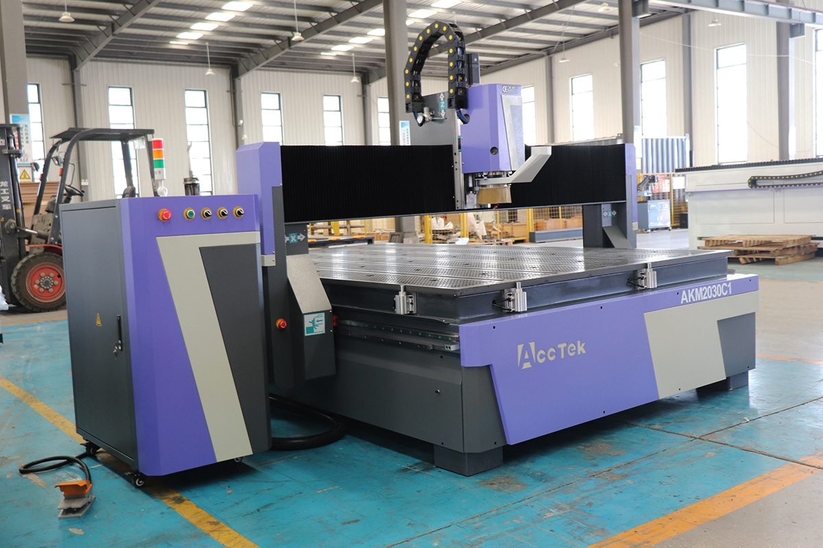
How To Block Noise From CNC Routers?
Noise is one of the most common challenges associated with CNC router operation, especially in workshops where machines run for long periods or at high spindle speeds. During cutting, engraving, drilling, and milling, CNC routers can generate significant noise from multiple sources, including the spindle motor, cutting tool, workpiece vibration, motion system, vacuum pump, dust collection system, cooling equipment, and compressed air. Depending on the machine configuration, material, tooling, and operating parameters, these combined sound sources can create an uncomfortable and potentially harmful working environment.
Excessive CNC router noise is more than an inconvenience. Prolonged exposure to high sound levels can contribute to hearing damage, operator fatigue, reduced concentration, communication difficulties, and lower workplace productivity. Noise may also indicate mechanical problems such as worn bearings, loose components, improper tool selection, excessive vibration, incorrect cutting parameters, or insufficient machine maintenance. For businesses operating CNC routers near offices, residential areas, schools, or other noise-sensitive environments, controlling sound can also be important for meeting workplace and local environmental requirements.
Effectively blocking CNC router noise usually requires a combination of controlling noise at its source, preventing vibration from spreading, enclosing noisy equipment, absorbing reflected sound, and protecting workers from remaining exposure. Solutions can range from simple measures such as optimizing spindle speed, using sharp cutting tools, tightening machine components, and installing vibration-isolation pads to more comprehensive systems such as acoustic enclosures, soundproof rooms, silencers, and quieter dust extraction equipment.
This article explains where CNC router noise comes from, what factors influence noise levels, and how different noise-control methods can be applied. Understanding these principles can help manufacturers create a quieter, safer, and more comfortable CNC machining environment without unnecessarily compromising cutting performance, production efficiency, or machine accessibility.
Table of Contents
Understanding CNC Router Noise
CNC routers generate noise through several interacting mechanical and acoustic processes. The spindle rotates at high speed, the cutting tool repeatedly contacts the workpiece, machine components vibrate, and auxiliary systems such as vacuum pumps and dust collectors operate continuously in the background. As a result, the sound heard around CNC routers is rarely produced by a single source. Instead, it is a combination of airborne sound, structure-borne vibration, cutting noise, motor noise, airflow noise, and resonance.
Understanding how CNC router noise is created is the first step toward controlling it effectively. Different types of noise require different treatment methods. Sound traveling through the air may be reduced with acoustic enclosures and sound-absorbing materials, while vibration transmitted through the machine frame or floor may require isolation pads, structural reinforcement, or improved machine maintenance. Noise also changes significantly according to the cutting operation, material, spindle speed, feed rate, tooling, and machine condition.
What Is CNC Router Noise
CNC router noise is the unwanted sound produced while the machine and its supporting equipment operate. It includes sound generated directly by the spindle, cutting tool, motors, bearings, guide systems, vacuum pumps, dust collectors, cooling systems, and compressed-air equipment, as well as sound created when these components cause other parts of the machine or building to vibrate.
Some CNC router noise is normal and unavoidable. A high-speed spindle naturally generates aerodynamic and mechanical sound, while a cutting tool produces noise whenever it removes material. However, excessive or unusual noise can indicate inefficient machining conditions or equipment problems.
For example, a sharp increase in cutting noise may result from a dull tool, excessive tool engagement, poor workpiece clamping, incorrect feed rate, or spindle-bearing wear. Therefore, identifying what constitutes normal operating noise and what represents abnormal noise is important for both noise control and machine maintenance.
How Sound Is Generated During CNC Routing
Sound is produced when mechanical energy causes air or solid materials to vibrate. During CNC routing, these vibrations originate from several sources.
The spindle motor and bearings create mechanical vibration as the spindle rotates, often at speeds of thousands or tens of thousands of revolutions per minute. The rotating cutting tool also disturbs surrounding air, producing aerodynamic noise.
When the cutting edge contacts the workpiece, rapidly changing cutting forces create additional vibration. Every cutting edge entering and leaving the material produces a small impact. At high rotational speeds, these impacts occur many times per second and can create strong tonal or high-frequency sounds.
The workpiece, cutting table, gantry, machine frame, and enclosure panels can respond to these forces and begin vibrating themselves. If their natural frequencies correspond to the excitation frequencies generated during machining, resonance may occur and significantly increase sound levels.
Auxiliary equipment contributes further noise. Vacuum pumps create mechanical and exhaust noise, dust collectors produce fan and airflow noise, and compressors generate motor, vibration, and pressure-release sounds. Together, these sources determine the overall acoustic environment around the CNC router.
Airborne Noise
Airborne noise travels from the sound source to the listener primarily through the surrounding air. It is one of the most noticeable types of CNC router noise.
Common sources include cutting-tool interaction, spindle rotation, cooling fans, vacuum exhaust, dust extraction airflow, compressed air, and uncovered motors. Once generated, the sound waves travel outward and may reflect from walls, ceilings, floors, machines, and other hard surfaces.
Workshops containing concrete floors, metal walls, glass windows, and other reflective materials can make airborne noise seem considerably louder because sound reflections remain within the room.
Acoustic enclosures are particularly effective for controlling airborne noise because they create a physical barrier between the machine and the surrounding workspace. Sound-absorbing materials can also reduce reflections inside the enclosure or workshop.
However, enclosures must be designed carefully. Gaps around doors, material openings, ventilation ducts, cable entrances, and dust extraction connections can allow significant amounts of sound to escape.
Structure-Borne Noise
Structure-borne noise occurs when vibration travels through solid materials rather than directly through the air. With CNC routers, vibration may pass from the spindle and cutting area into the gantry, machine frame, machine feet, floor, walls, and surrounding structures.
Once vibration reaches another surface, that surface may act like a loudspeaker and convert the mechanical vibration back into airborne sound.
For example, vibration from a router mounted directly on a concrete floor may spread through the building structure. Nearby walls, platforms, or metal panels can then radiate additional noise.
Structure-borne noise can sometimes travel farther than expected, especially in large industrial buildings with rigid steel or concrete structures.
Reducing it often requires vibration isolation rather than acoustic absorption alone. Rubber pads, elastomer mounts, vibration-isolation feet, properly designed foundations, and separation from structural walls can help reduce vibration transmission.
Improving machine rigidity can also help because a stable frame is less likely to amplify cutting forces.
Vibration-Induced Noise
Vibration-induced noise is closely related to structure-borne noise but focuses specifically on sound created when machine components or workpieces vibrate excessively.
Many parts of CNC routers can act as resonating surfaces. Sheet-metal covers, electrical cabinet panels, dust collection ducts, vacuum tables, workpieces, guarding panels, and machine frames may begin vibrating when excited by the spindle or cutting process.
Thin or poorly supported workpieces are particularly susceptible. Large sheets of wood, plastic, composite material, or aluminum can sometimes behave like vibrating diaphragms, amplifying cutting noise.
Tool chatter is another major source of vibration-induced noise. Chatter is a self-excited vibration that develops between the cutting tool and workpiece. It often produces a loud, repetitive, or squealing sound and may reduce surface quality while accelerating tool wear.
Controlling vibration-induced noise may involve improving workpiece clamping, selecting more appropriate tools, optimizing spindle speed and feed rate, improving machine rigidity, tightening loose panels, and adding damping materials where necessary.
Continuous Noise Versus Intermittent Noise
CNC router noise can generally be divided into continuous and intermittent components.
Continuous noise remains relatively steady while equipment operates. Typical examples include spindle motor sound, vacuum pump operation, extraction fans, cooling fans, and some types of compressed-air systems. Even when the cutting tool is not contacting the material, these systems may continue producing significant background noise.
Intermittent noise changes according to machine movement or cutting conditions. It may include tool engagement, rapid acceleration, drilling, material breakthrough, tool changes, pneumatic clamps, automatic tool changers, or parts impacting collection surfaces.
Intermittent noise can sometimes be more disturbing than continuous noise because sudden changes attract attention and may include short-duration sound peaks.
Noise-control planning should therefore consider both average sound exposure and individual peak events. An enclosure that significantly reduces steady spindle noise, for example, may still allow impact noise from tool changes or material handling to remain noticeable.
Typical Noise Characteristics of CNC Routers
CNC routers typically produce a combination of low-, medium-, and high-frequency sounds.
High-frequency noise often comes from high-speed spindles, cutting-tool contact, compressed air, and airflow through dust collection systems. These sounds may be perceived as whining, hissing, or squealing.
Medium-frequency sounds may originate from motors, bearings, cutting forces, and machine structures. Low-frequency noise is often associated with vacuum pumps, dust collectors, larger motors, structural vibration, and resonance.
CNC router sound levels are rarely constant. The noise spectrum changes as spindle speed, tool type, cutting depth, material, and machine movement change.
A machine cutting thick hardwood with a large-diameter router bit may sound very different from the same machine engraving acrylic using a small tool. Likewise, a vacuum table may add a strong low-frequency background sound even before machining begins.
Changes in sound can also provide useful diagnostic information. Experienced operators may recognize abnormal bearing noise, chatter, loose components, tool damage, or poor cutting conditions simply from changes in the acoustic signature of the machine.
How Noise Changes During Different Machining Operations
The type of machining operation has a major influence on CNC router noise.
During engraving or shallow cutting, the cutting forces are relatively small, so noise may be dominated by the spindle itself. Small tools operating at high spindle speeds can create noticeable high-frequency sound even when material removal is limited.
During deep cutting or profiling, greater tool engagement increases cutting forces and vibration. Larger amounts of material are removed during each tool revolution, which can produce louder and more complex sound.
Slotting operations can be particularly noisy because a large portion of the cutter may remain continuously engaged with the material, generating higher loads and providing limited space for chip evacuation.
Drilling and plunging operations may produce short bursts of noise as the tool enters the material. Poor chip evacuation during plunging can increase friction, vibration, and sound.
Pocketing operations frequently involve changing cutting directions and varying tool engagement, causing noise levels to fluctuate throughout the toolpath.
Finishing passes generally generate lower cutting forces than roughing operations, although high spindle speeds may still produce significant high-frequency sound.
Rapid machine movements create another type of noise. Servo motors, stepper motors, rack-and-pinion systems, ball screws, bearings, and linear guides can generate noticeable sound during rapid acceleration and deceleration.
Automatic tool-changing systems may produce short, sharp noises from pneumatic cylinders, tool-release mechanisms, and magazine movement. Vacuum pumps and dust collectors may continue operating throughout all these machining stages, creating a constant background noise level.
Material also changes the acoustic characteristics of machining. Dense hardwoods, laminated materials, plastics, composites, foam, and nonferrous materials all interact differently with cutting tools. Therefore, the same CNC router may produce very different sound levels and frequencies depending on the application.
CNC router noise is produced by a combination of spindle rotation, cutting-tool interaction, machine movement, vibration, airflow, and auxiliary equipment. Some of this sound travels directly through the air, while other noise is generated when vibration passes through the machine frame, workpiece, floor, or building structure.
Airborne noise is commonly associated with cutting, spindles, fans, compressed air, and dust extraction, while structure-borne noise results from vibration transmitted through solid machine and building components. Vibration-induced noise can become especially severe when workpieces, panels, tools, or machine structures resonate or when unstable cutting conditions produce chatter.
CNC routers also generate both continuous and intermittent sound. Continuous sources such as vacuum pumps, dust collectors, and spindle motors create steady background noise, while machining operations, tool changes, rapid movements, and material impacts produce changing or sudden sound levels.
Because noise characteristics vary with machining operation, tool selection, material, spindle speed, feed rate, cutting depth, machine rigidity, and equipment condition, there is no single source responsible for all CNC router noise. Effective noise reduction therefore begins with identifying where the sound originates, how it travels, and which operating conditions make it worse. This understanding provides the foundation for selecting suitable solutions such as parameter optimization, vibration isolation, acoustic absorption, soundproof enclosures, machine maintenance, and improved workshop design.
Main Sources of CNC Router Noise
CNC router noise does not come from a single component. It is produced by a combination of rotating equipment, cutting forces, mechanical movement, vibration, airflow, and supporting systems. In many workshops, the loudest sound may not even come from the cutting process itself. A vacuum pump, dust collector, compressed-air line, or worn spindle bearing can contribute just as much to the overall noise level.
Identifying the dominant noise sources is important because different sources require different control methods. Spindle noise may be reduced through maintenance or by choosing a quieter spindle design, while cutting noise may require changes to tools, parameters, or workholding. Structure-borne vibration may need damping or isolation, whereas fan and airflow noise may require silencers, duct modifications, or acoustic enclosures. Understanding each source makes it easier to choose practical noise-reduction measures without compromising CNC router performance.
Spindle and Router Motor Noise
The spindle or router motor is one of the most persistent noise sources on CNC routers. Because it operates at very high rotational speeds, often continuously throughout the machining cycle, even a well-maintained spindle produces a recognizable high-frequency sound. Noise levels can increase significantly when bearings wear, cooling fans become unbalanced, or the spindle operates outside its ideal speed range.
Motor Rotation
Motor rotation creates electromagnetic, mechanical, and aerodynamic noise. As the rotor spins inside the motor housing, small imbalances and electromagnetic forces generate vibration. At high spindle speeds, these vibrations can produce a steady whine or humming sound.
The frequency and intensity of motor noise usually increase with spindle speed. A spindle operating at 24,000 RPM, for example, will typically produce a higher-pitched sound than one running at 12,000 RPM.
Excessive motor vibration may indicate rotor imbalance, loose components, damaged mounts, electrical problems, or mechanical wear. Proper balancing and secure mounting help reduce unwanted noise.
Bearing Noise
Bearings support the spindle shaft and allow it to rotate accurately at high speed. When bearings are in good condition and correctly lubricated or sealed, they generally operate with limited noise.
As bearings wear, however, they can produce grinding, humming, squealing, or rattling sounds. Bearing defects also increase spindle vibration, which can then be transmitted through the spindle mount and machine frame.
Contamination, overheating, improper preload, crashes, excessive radial loads, or prolonged high-speed operation can accelerate bearing deterioration. A noticeable change in spindle sound should therefore be investigated rather than treated only as an acoustic problem.
Cooling-Fan Noise
Air-cooled spindles and router motors usually contain cooling fans. These fans generate aerodynamic noise as they move large volumes of air across the motor housing.
At high speed, fan blades can create a strong rushing or whining sound. Dust accumulation, damaged fan blades, worn fan bearings, or imbalance can further increase noise.
Fan noise can be particularly noticeable when the machine is idling because cutting noise is absent. Regular cleaning and inspection of cooling fans can help prevent unnecessary noise and maintain proper motor cooling.
Air-Cooled Versus Water-Cooled Spindles
Air-cooled spindles tend to generate more airborne noise because they rely on internal or external fans for heat removal. The fan continues producing sound even when the spindle is not cutting material.
Water-cooled spindles generally operate more quietly because they do not require a high-speed cooling fan on the spindle itself. Cooling is instead provided by circulating water through internal channels.
However, water-cooled systems are not completely silent. Pumps, chillers, cooling fans, and liquid flow can still contribute to the overall noise level.
For applications where noise reduction is an important priority, water-cooled spindles may offer an acoustic advantage, especially in enclosed workshops or small production spaces.
Cutting Noise
Cutting noise is produced when the rotating tool interacts with the workpiece. It is often one of the most variable sources of CNC router noise because it depends heavily on material, tool condition, spindle speed, feed rate, cutting depth, toolpath strategy, and machine rigidity.
Some cutting operations generate a relatively smooth sound, while others produce sharp impacts, squealing, buzzing, or chatter.
Tool-Workpiece Contact
Each cutting edge repeatedly enters and exits the workpiece. This repeated contact creates rapidly changing forces that cause the tool, spindle, workpiece, and machine structure to vibrate.
The resulting sound depends on chip load and cutting conditions. Very light cutting can sometimes create a high-pitched rubbing sound, while excessive cutting loads may produce a harsh or irregular sound.
Stable engagement between the cutting edge and material generally produces smoother, more predictable noise.
Material Fracture and Chip Formation
Noise is also generated as material is fractured, sheared, or separated into chips.
Different materials behave differently during machining. Wood fibers may tear or fracture, plastics may shear or melt, and composite materials may break in a more brittle manner. Each mechanism produces different sound characteristics.
Larger cutting depths and aggressive material removal rates usually increase cutting forces and chip formation, which can raise noise levels.
Proper tool geometry, feed rate, and spindle speed help produce controlled chip formation and reduce excessive vibration.
Tool Impact During Interrupted Cutting
Interrupted cutting occurs when the cutting edge repeatedly enters and leaves the material rather than remaining continuously engaged.
This can happen when machining profiles, slots with varying engagement, rough surfaces, interrupted workpieces, or components containing gaps and openings.
Each re-entry produces a small impact. At high spindle speeds, these repeated impacts occur rapidly and can create a strong tonal or hammering-type noise.
The severity of interrupted-cutting noise depends on tool diameter, flute count, engagement, spindle speed, and material stiffness.
Cutting-Tool Noise
The cutting tool itself has a major influence on CNC router noise. Two tools performing the same operation can produce very different sound levels depending on their geometry, diameter, number of cutting edges, sharpness, and balance.
Tool selection should therefore be considered part of noise-control planning.
Tool Geometry
Tool geometry determines how the cutting edge enters the material and how cutting forces are distributed.
Rake angle, clearance angle, helix angle, cutting-edge shape, and flute design all influence cutting resistance and vibration.
A tool designed specifically for the material usually cuts more smoothly than a general-purpose tool. Smooth cutting reduces impact forces and lowers the likelihood of chatter.
Compression bits, up-cut bits, down-cut bits, straight bits, and specialty cutters each create different cutting-force directions and acoustic characteristics.
Tool Diameter
Tool diameter affects both cutting forces and aerodynamic noise.
Large-diameter tools remove more material per revolution and may generate higher cutting forces. They can also disturb more air as they rotate, particularly at high spindle speeds.
Small-diameter tools may produce lower absolute cutting forces but often operate at high rotational speeds, which can create a higher-pitched sound.
The correct diameter should be chosen according to material, machining depth, desired productivity, and machine rigidity rather than noise alone.
Number of Flutes
The number of flutes determines how frequently cutting edges contact the workpiece during each spindle revolution.
A higher flute count increases tooth-passing frequency, which can shift cutting noise toward higher frequencies. It can also reduce chip space and increase heat if feed rate is not adjusted appropriately.
Fewer flutes provide greater chip-clearance capacity and may be better for high-speed routing of wood and some plastics.
Regardless of flute count, correct feed per tooth is important. Improper chip load can cause rubbing, vibration, and excessive noise.
Tool Sharpness
Sharp tools generally cut more efficiently and quietly than dull tools.
As cutting edges wear, more force is required to remove material. Instead of cleanly shearing the workpiece, the tool may begin rubbing, crushing, or tearing it.
This increases friction, heat, vibration, and noise. Dull tools can also generate burning marks, poor surface finish, and higher spindle loads.
Regular tool inspection and replacement can therefore improve both cutting quality and acoustic conditions.
Tool Runout
Tool runout occurs when the cutting tool does not rotate perfectly around the spindle centerline.
Even small amounts of runout can cause one flute to remove more material than the others, creating uneven cutting forces and repetitive vibration.
Excessive runout may result from damaged collets, dirty tool holders, incorrect tool installation, worn spindle bearings, bent tools, or poor-quality tooling.
Because runout produces cyclic loading, it can create a distinctive buzzing or pulsing noise. Maintaining clean, accurate tool-holding systems helps reduce this problem.
Motion-System Noise
The motion system positions the spindle and cutting tool along the machine axes. Although movement noise is usually less intense than cutting noise, it can become significant during rapid positioning, acceleration, deceleration, and direction changes.
Poorly maintained motion components can also generate grinding, knocking, rattling, or squealing sounds.
Servo and Stepper Motors
Servo and stepper motors create electromagnetic and mechanical noise as they accelerate and control axis movement.
Stepper motors often produce a characteristic humming or buzzing sound, particularly at certain speeds where resonance occurs.
Servo systems are typically smoother but can still create high-frequency sounds during rapid acceleration or when servo tuning is poor.
Abnormal motor noise may indicate incorrect tuning, overload, damaged bearings, loose couplings, or mechanical resistance.
Rack-and-Pinion Systems
Rack-and-pinion drives are commonly used on large CNC routers because they provide fast movement over long travel distances.
Noise can be generated as the pinion teeth repeatedly engage with the rack. Incorrect gear meshing, insufficient lubrication, contamination, worn teeth, or excessive backlash can make the drive significantly louder.
Poor alignment can also create repetitive clicking or grinding.
Proper lubrication, alignment, and preload help maintain quieter rack-and-pinion operation.
Ball Screws
Ball screws are often quieter than rack-and-pinion systems when properly installed and maintained.
However, noise may develop from worn ball nuts, inadequate lubrication, contamination, misalignment, or damaged screw surfaces.
At high axis speeds, ball circulation inside the nut can also create a characteristic mechanical sound.
Sudden changes in ball-screw noise should be inspected because they may indicate increasing wear or lubrication problems.
Linear Guides and Bearings
Linear guides support machine axes and allow smooth, accurate motion.
Contamination, lack of lubrication, misalignment, damaged bearing blocks, or worn raceways can create scraping, clicking, or grinding sounds.
Because cutting dust can easily enter exposed motion components, regular cleaning and lubrication are important.
A smooth motion system not only operates more quietly but also contributes to improved positioning accuracy and longer machine life.
Machine-Frame Vibration
The machine frame can amplify noise when cutting forces or rotating components cause it to vibrate.
Rigid CNC router frames resist deformation and generally produce less vibration-induced noise. Lightweight or poorly reinforced frames can resonate more easily, especially during aggressive cutting.
Loose bolts, poorly supported gantries, weak joints, or insufficient foundation support can also increase frame vibration.
When resonance occurs, relatively small cutting forces may create surprisingly loud sound because large machine surfaces begin radiating acoustic energy.
Improving frame rigidity, tightening structural connections, installing damping materials, and using appropriate vibration-isolation mounts can help reduce these effects.
Workpiece Vibration
The workpiece itself can become a significant sound source.
Large sheets, thin panels, long narrow components, and poorly supported parts can vibrate like membranes during cutting. These vibrations may amplify sound far beyond the noise produced by the cutting edge alone.
Insufficient clamping is a common cause. If the workpiece can move, flex, or lift from the cutting table, cutting forces may create chatter and rattling.
Vacuum tables, mechanical clamps, fixtures, additional support blocks, or temporary tabs can improve stability.
Workpiece geometry also matters. Large unsupported areas are more likely to resonate than small, rigid components. Machining strategy should therefore consider how material stiffness changes as sections are removed.
Vacuum-Pump Noise
Vacuum pumps are commonly used to hold sheet materials on CNC router tables. Depending on their type and size, they can be among the loudest pieces of equipment in the workshop.
Rotary vane pumps, regenerative blowers, and other vacuum systems generate mechanical, airflow, and exhaust noise. Some units produce strong low-frequency sound that can travel through walls and floors.
Pump vibration may also be transmitted into the building structure when the unit is rigidly mounted.
Noise can often be reduced by locating the vacuum pump in a separate equipment room, using vibration-isolation mounts, installing intake or exhaust silencers, and maintaining adequate airflow around the unit.
Any enclosure must provide enough ventilation to prevent overheating.
Dust-Collector Noise
Dust collection systems create noise from several sources, including electric motors, high-speed fans, air turbulence, duct vibration, and particles striking duct walls or collection containers.
Large dust collectors can generate continuous background noise even when cutting itself is relatively quiet.
Airflow noise may become especially strong at narrow ducts, elbows, dampers, or poorly designed transitions. Flexible ducts can also vibrate or flap under high airflow.
Locating dust collectors away from operators can reduce exposure. Acoustic enclosures, silencers, vibration isolation, properly sized ductwork, and well-designed airflow paths can provide additional reductions.
However, dust-collection performance should never be sacrificed simply to reduce noise.
Compressed-Air Noise
Compressed air is used on some CNC routers for chip clearing, tool cooling, automatic tool changers, pneumatic clamps, actuators, and cleaning operations.
When compressed air is released through an open nozzle, it can generate extremely sharp, high-frequency noise. Small leaks can also create continuous hissing sounds that increase background noise and waste energy.
High-pressure blow-off operations are particularly noisy when air strikes the tool, workpiece, machine surface, or enclosure.
Noise can be reduced by repairing leaks, lowering pressure to the minimum effective level, using engineered low-noise air nozzles, and avoiding unnecessary continuous air flow.
Pneumatic exhaust silencers may also be installed where appropriate.
Cooling-System Noise
CNC router cooling equipment may include spindle chillers, water pumps, radiator fans, cabinet cooling fans, and refrigeration compressors.
Water-cooled spindle systems typically move the spindle’s cooling noise away from the machining head, but the chiller itself can still produce noticeable sound.
Cooling fans generate continuous airflow noise, while refrigeration compressors may create low-frequency vibration or cycling noise.
Poor maintenance can increase sound levels. Dirty filters force fans to work harder, loose panels may vibrate, worn fan bearings can produce rattling, and pumps may become noisy if coolant levels are too low.
Locating cooling equipment away from the operator station and maintaining it regularly can help minimize its contribution to workshop noise.
Auxiliary Equipment Noise
Many CNC router installations include additional equipment that contributes to the overall acoustic environment.
Examples include air compressors, transformers, voltage stabilizers, automatic loading systems, tool changers, rotary devices, lubrication pumps, chip conveyors, extraction fans, electrical cabinet fans, automatic lubrication systems, and material-handling equipment.
Each device may appear relatively quiet when evaluated individually, but multiple sources operating simultaneously can significantly increase total noise exposure.
Automatic tool changers, for example, may produce sudden impact and pneumatic sounds. Air compressors can create strong motor and vibration noise. Loading systems can generate mechanical impact when sheets or components contact support structures.
Noise-control planning should therefore evaluate the entire CNC workstation rather than focusing only on the router itself.
The main sources of CNC router noise include the spindle, cutting process, cutting tools, motion system, machine frame, workpiece, vacuum pump, dust collector, compressed-air system, cooling equipment, and other auxiliary machinery. These sources create different types of sound and vibration, and their relative importance changes according to machine design and operating conditions.
Spindle noise can originate from motor rotation, bearings, and cooling fans, while cutting noise results from repeated tool-workpiece contact, material removal, and interrupted cutting. Cutting-tool geometry, diameter, flute count, sharpness, and runout can further influence vibration and sound levels.
Mechanical movement also contributes through servo motors, stepper motors, rack-and-pinion drives, ball screws, and linear guides. Meanwhile, insufficient machine rigidity or poor workpiece support can turn structural components into effective sound radiators.
Supporting systems should not be overlooked. Vacuum pumps and dust collectors often run continuously and can produce substantial low- and medium-frequency noise, while compressed air can generate intense high-frequency sound. Cooling systems and auxiliary equipment add further background and intermittent noise.
Effective CNC router noise control begins by identifying which sources dominate in a specific installation. Once those sources are understood, manufacturers can apply targeted solutions such as equipment maintenance, improved tooling, optimized cutting parameters, vibration isolation, acoustic enclosures, silencers, better workholding, remote equipment placement, and improved workshop design. Addressing several major sources together usually provides much better results than attempting to block all CNC router noise with a single method.
Factors That Determine CNC Router Noise Levels
CNC router noise levels vary considerably from one machining job to another. Even when the same machine is used, changing the spindle speed, feed rate, cutting depth, tool, material, or workholding method can produce a noticeably different sound. Noise is therefore not determined only by the rated power or size of the CNC router. It results from the interaction between the machine, cutting tool, workpiece, operating parameters, and surrounding workshop.
Some factors affect noise directly by increasing cutting forces or rotational speed, while others influence how strongly vibration is generated and transmitted. A dull cutting tool, for example, may create higher forces and more chatter, while a thin, poorly clamped workpiece may amplify those forces by vibrating like a panel. Workshop walls and ceilings can then reflect the resulting sound and make the machine appear even louder.
Understanding these factors helps operators reduce noise at its source before relying entirely on soundproofing. In many cases, selecting suitable machining parameters, maintaining tools and machines, improving workholding, and controlling vibration can significantly reduce CNC router noise while also improving cutting quality and tool life.
Spindle Speed
Spindle speed is one of the most important factors affecting CNC router noise. Increasing rotational speed raises the frequency at which the cutting edges pass through the material and can increase both mechanical and aerodynamic sound.
At high speeds, the spindle itself may produce a stronger high-frequency whine. Cutting tools also move more air, which contributes additional aerodynamic noise. The tooth-passing frequency increases as well, shifting cutting noise toward higher frequencies.
However, reducing spindle speed does not automatically make machining quieter. If the speed becomes too low for the selected feed rate, chip load may become excessive, increasing cutting forces and vibration. Conversely, an excessively high spindle speed combined with a low feed rate can cause the tool to rub rather than cut efficiently, producing heat, squealing, and unnecessary noise.
The best approach is to select spindle speed together with feed rate so that the tool operates within an appropriate chip-load range. Stable cutting usually produces a smoother sound than either excessive rubbing or overloaded cutting.
Feed Rate
Feed rate determines how quickly the cutting tool moves through the material and directly affects chip thickness and cutting forces.
If the feed rate is too high, each cutting edge removes an excessive amount of material. This increases tool load, spindle load, vibration, and the possibility of chatter. The resulting sound may become harsh, irregular, or unusually loud.
If the feed rate is too low, the cutting edge may remove very thin chips or begin rubbing against the material. Rubbing produces friction, heat, and high-frequency squealing. It can also accelerate tool wear, which further increases noise.
A correctly selected feed rate allows each flute to remove an appropriate chip thickness. This improves cutting efficiency and usually creates a more consistent acoustic signature.
Because feed rate must match spindle speed, tool diameter, flute count, material, and cutting depth, it should not be adjusted independently when attempting to reduce noise.
Cutting Depth
Cutting depth determines how much of the tool engages with the material during each pass.
Increasing cutting depth generally increases cutting forces because more material is removed simultaneously. Higher forces can cause stronger vibration in the tool, spindle, workpiece, and machine frame.
Very deep cuts may cause the spindle to work closer to its load limit, particularly when using smaller-diameter tools. This can produce louder cutting sounds, chatter, poor surface finish, and accelerated tool wear.
Reducing depth per pass can lower instantaneous cutting forces and may make machining quieter. However, it also increases the number of passes required, which extends total machining time and therefore increases the duration of noise exposure.
The objective is not necessarily to use the shallowest possible cut but to select a cutting depth that maintains stable tool engagement without overloading the tool or machine.
Step-Over
Step-over is the lateral distance between adjacent tool passes, usually expressed as a percentage of tool diameter. It is particularly important during pocketing, surface machining, and three-dimensional routing.
A large step-over increases radial tool engagement and can significantly raise cutting forces. Greater engagement may produce more vibration and noise, particularly on lightweight CNC routers or when machining rigid materials.
A smaller step-over reduces the amount of material removed during each pass, generally producing smoother cutting forces. This can reduce noise and improve surface finish, although machining time increases.
Extremely small step-over values are not always acoustically ideal, however. Depending on tool geometry and material, insufficient engagement can cause rubbing rather than efficient chip formation.
Step-over should therefore be optimized according to tool size, cutting depth, material, machine rigidity, and required finish.
Tool Diameter
Tool diameter affects cutting forces, rotational dynamics, air movement, and the amount of material removed during machining.
Larger-diameter tools are generally stiffer and less susceptible to deflection, which can help reduce chatter. However, they often engage more material and can generate greater cutting forces. At high spindle speeds, larger cutters also produce stronger aerodynamic noise.
Small-diameter tools remove less material per revolution but are less rigid and more vulnerable to deflection. When pushed too aggressively, they may vibrate or chatter, producing high-pitched noise.
Tool diameter should therefore match the required cutting depth, feature size, material, and spindle capability.
For deep cuts and heavy material removal, a larger and more rigid cutter may actually operate more quietly than a smaller tool that is being overloaded. For fine engraving or detailed machining, smaller tools may be necessary, but suitable speeds and feeds are especially important.
Tool Geometry
Cutting-tool geometry strongly influences the way forces are generated during machining.
Rake angle, cutting-edge shape, flute design, helix angle, clearance angle, and cutting direction all affect how easily the tool enters the material and removes chips.
Tools designed for a specific material usually generate lower cutting resistance than poorly matched tools. A cutter that shears material cleanly creates smoother forces and less vibration, while unsuitable geometry may tear, scrape, crush, or rub the material.
Up-cut, down-cut, and compression cutters also direct forces differently. An up-cut tool may tend to lift the workpiece, potentially increasing vibration if clamping is inadequate. A down-cut tool pushes the workpiece toward the table, which may improve stability but can restrict chip evacuation in some operations.
Specialized tools for plastics, composites, foam, or wood can often produce lower noise because their geometry supports cleaner chip formation.
Tool Condition
Tool condition has a major effect on both CNC router noise and machining quality.
A sharp cutting edge removes material efficiently with relatively low resistance. As the tool becomes dull, cutting forces rise, and more friction is generated. The tool may begin rubbing, tearing, or crushing material rather than shearing it cleanly.
This often causes an obvious increase in noise. Operators may hear squealing, chatter, rough cutting sounds, or irregular vibration.
Tool damage can create even more severe problems. Chipped cutting edges cause unequal loading between flutes, while bent tools create runout and repeated impact forces.
Resin buildup, adhesive residue, melted plastic, and dust can also affect tool performance and increase friction.
Regular inspection, cleaning, sharpening where appropriate, and replacement of worn tools are therefore effective ways to control both noise and cutting quality.
Material Type
Material characteristics strongly influence CNC router noise because different materials respond differently to cutting forces.
Density, hardness, elasticity, brittleness, internal structure, fiber direction, and thermal properties all affect chip formation and vibration. A soft foam panel behaves very differently from hardwood, acrylic, composite sheet, or stone.
The correct tool and machining parameters should therefore be selected specifically for the material being processed.
Wood
Solid wood can generate moderate to high cutting noise depending on species, grain direction, moisture content, hardness, and cutting direction.
Hardwoods generally require greater cutting forces than softwoods, potentially producing higher noise levels. Changes in grain direction can cause cutting forces to fluctuate, creating variations in sound.
Knots and other dense areas may produce sudden increases in cutting load and noise.
Sharp woodworking cutters and appropriate chip loads help produce clean shearing rather than tearing, reducing unnecessary vibration.
MDF and Particleboard
MDF and particleboard have relatively uniform structures compared with natural wood, which can provide consistent cutting behavior.
However, their high density and abrasive content can create considerable cutting resistance. MDF in particular produces large quantities of fine dust, which requires strong extraction systems. The dust collector may therefore become an important secondary noise source.
These engineered materials can also dull cutting tools relatively quickly. As tool wear increases, routing noise may become progressively louder.
Maintaining sharp tooling and efficient dust extraction is particularly important when machining MDF and particleboard.
Plywood
Plywood consists of multiple bonded wood veneers with alternating grain directions.
As the cutting tool passes through different layers, cutting resistance changes continuously. Adhesive layers can also increase tool wear and cutting forces.
This alternating structure may produce a slightly harsher acoustic signature than uniform materials.
Using sharp compression cutters or suitable up-cut/down-cut tooling can reduce edge tear-out and stabilize cutting.
Thin plywood sheets can also vibrate strongly if vacuum hold-down or mechanical clamping is insufficient, making workpiece support especially important.
Plastics
Plastic materials vary widely in hardness, elasticity, thermal sensitivity, and machinability.
Some plastics cut smoothly and quietly, while others may generate squealing if the tool rubs instead of forming proper chips.
Heat buildup is a common problem. Excessive spindle speed or insufficient feed can melt the material, causing it to stick to the cutting edges. This increases cutting resistance and may lead to irregular noise.
Tools with polished flutes, suitable rake angles, and good chip clearance often improve plastic machining.
Effective chip evacuation and correct spindle speed/feed combinations can significantly reduce both noise and heat.
Acrylic
Acrylic is relatively rigid and brittle, so machining can produce distinctive high-frequency cutting noise.
When parameters are correct, acrylic forms clean chips and can be machined smoothly. However, dull tools, insufficient feed, or excessive spindle speed can cause rubbing and melting, resulting in squealing.
Excessive cutting forces can also cause edge chipping or cracking.
Single-flute or specialized plastic-cutting tools are commonly used because they provide good chip evacuation and can reduce heat accumulation.
Secure workholding is also important because large acrylic sheets can vibrate and amplify cutting noise.
Foam
Foam generally requires very low cutting forces and is usually quieter to machine than dense materials.
However, high-speed spindle rotation and tool airflow may still produce noticeable noise even when the cutting process itself is relatively quiet.
Because foam is lightweight, inadequate hold-down can allow the material to move or flutter during machining. This can produce irregular cutting sounds and poor dimensional accuracy.
Vacuum hold-down or suitable mechanical positioning methods can stabilize the workpiece.
For some foam applications, specialized cutters and lower spindle speeds can reduce unnecessary aerodynamic noise.
Composite Materials
Composite materials can produce relatively high noise because they often combine fibers, resins, laminates, or mineral fillers with very different mechanical properties.
Fiber-reinforced composites, for example, may require high cutting forces and can rapidly wear conventional tools. Dull tools then increase vibration and noise further.
Delamination, fiber pullout, and interrupted cutting between different layers can also create unstable acoustic conditions.
Specialized carbide, diamond-coated, or polycrystalline diamond tools may provide cleaner cutting and longer service life.
Dust and particle extraction requirements can also increase overall workshop noise because powerful collection systems are often needed.
Stone and Other Hard Materials
Stone and similarly hard materials can generate substantial noise during CNC routing or engraving.
High cutting resistance, brittle fracture, and contact between hard cutting tools and mineral surfaces can create strong high-frequency sound and vibration.
Machine rigidity becomes especially important because cutting forces are transferred directly into the spindle, gantry, workpiece, and frame.
Water cooling may help control heat, dust, and some airborne sound, but pumps and cooling systems contribute their own background noise.
Specialized diamond tooling, controlled depth of cut, stable feed rates, strong workholding, and rigid machine construction are essential for controlling vibration and maintaining acceptable noise levels.
Workpiece Thickness and Rigidity
Workpiece thickness influences how easily the material vibrates during machining.
Thin sheets are generally more prone to vibration than thick, rigid workpieces. A large thin panel can behave like a speaker diaphragm, converting cutting vibration into airborne sound.
As material is removed, the remaining workpiece may become less rigid. This means noise can increase toward the end of a machining operation even though cutting parameters remain unchanged.
Thick, dense workpieces are generally more resistant to vibration, although they may require higher cutting forces.
Supporting large sheets across their entire surface, maintaining vacuum pressure, and adjusting machining sequence can help reduce panel vibration.
For thin components, additional fixtures, sacrificial boards, tabs, or temporary supports may be necessary.
Workpiece Clamping
Workpiece clamping has a direct effect on machining stability and noise.
A securely clamped workpiece resists movement and vibration, allowing cutting forces to remain predictable. Poorly secured material can vibrate, lift, slide, or rattle against the table.
Vacuum tables are commonly used for sheet materials, but hold-down force depends on pump capacity, leakage, spoilboard condition, workpiece surface area, and material permeability. Small parts or porous materials may not receive sufficient vacuum force.
Mechanical clamps can provide strong localized holding but must be positioned carefully to prevent interference with the cutting tool.
Fixtures should support the workpiece without allowing large unsupported regions to vibrate.
When routing noise suddenly becomes louder in a specific part of the toolpath, inadequate workpiece support is one possible cause.
Machine Size and Construction
Machine size and structural design influence how vibration is generated and transmitted.
Large industrial CNC routers are often constructed from heavy welded steel frames, reinforced gantries, and rigid linear-motion systems. Their greater mass and stiffness can help absorb cutting forces and reduce vibration.
Smaller or lightweight machines may be more susceptible to structural resonance, especially during aggressive cutting.
However, large machines also have larger panels, covers, tables, and structures that may radiate sound if not properly damped.
Frame geometry, gantry stiffness, spindle mounting, bearing spacing, machine mass, and foundation design all influence acoustic behavior.
A well-designed rigid machine generally permits heavier machining while maintaining stable noise levels, whereas a flexible machine may develop chatter even under relatively moderate cutting loads.
Machine Condition
A CNC router in poor mechanical condition is usually noisier than one that is properly maintained.
Worn spindle bearings can produce grinding or whining sounds. Loose bolts and panels can rattle. Worn rack-and-pinion drives may click or knock. Dry linear guides may squeal, and damaged bearings may produce repetitive mechanical noise.
Tool-holder contamination and spindle runout can create uneven cutting forces. Misalignment can increase resistance in motion systems, while dirty cooling fans and dust collectors can create additional airflow noise.
Preventive maintenance therefore plays an important role in noise management.
Operators should investigate changes in machine sound because abnormal noise can provide an early indication of mechanical deterioration. Correcting the underlying problem can reduce noise while preventing more expensive damage.
Workshop Acoustics
The workshop itself can significantly influence how loud a CNC router appears.
Hard surfaces such as concrete floors, metal walls, glass windows, and exposed ceilings reflect sound rather than absorbing it. Multiple reflections can create a reverberant environment in which sound persists after leaving the machine.
Large empty workshops may therefore feel louder than spaces containing acoustic absorption, storage racks, partitions, or other sound-damping elements.
Room geometry also matters. Parallel hard surfaces can create strong reflections, while corners can reinforce certain low-frequency sounds.
The location of the CNC router affects operator exposure as well. A machine positioned close to a wall may experience stronger reflected noise than one placed farther away. Multiple machines operating in the same area can cause sound levels to accumulate.
Acoustic wall panels, ceiling absorbers, barriers, partial enclosures, dedicated CNC rooms, and strategic machine placement can improve workshop acoustics. These treatments are most effective when combined with noise reduction at the machine itself.
CNC router noise levels are determined by the combined effects of machining parameters, cutting-tool characteristics, material properties, workpiece stability, machine design, equipment condition, and workshop acoustics. No single parameter controls the overall sound level, which is why effective noise reduction requires evaluating the complete machining process.
Spindle speed and feed rate influence chip load, cutting frequency, and aerodynamic sound, while cutting depth and step-over determine how heavily the tool engages the material. Tool diameter, geometry, and condition affect cutting forces and vibration. Sharp, correctly selected tools operating at suitable speeds and feeds generally produce smoother and quieter machining than worn or poorly matched cutters.
Material type is equally important. Wood, engineered boards, plywood, plastics, acrylic, foam, composites, and stone have different hardness, rigidity, fracture behavior, and acoustic characteristics. Workpiece thickness and clamping further determine whether cutting vibration remains controlled or is amplified by the material.
Machine size, frame rigidity, spindle condition, bearings, motion components, and maintenance also affect sound generation. Finally, workshop surfaces can reflect and reinforce noise, increasing operator exposure even when machine-generated sound remains unchanged.
Reducing CNC router noise therefore begins with controlling the factors that create vibration and inefficient cutting. Optimizing machining parameters, selecting appropriate tooling, maintaining sharp cutters, securing the workpiece, keeping the machine in good condition, and improving workshop acoustics can substantially reduce noise before additional soundproofing measures are applied.
Measuring CNC Router Noise Before Trying to Block It
Before adding acoustic panels, building an enclosure, replacing equipment, or changing machining parameters, it is important to understand how much noise the CNC router actually produces and where that noise comes from. Noise measurement provides an objective starting point for identifying the loudest sources, evaluating operator exposure, and determining whether a noise-control modification is effective.
Without measurement, noise reduction can easily become a trial-and-error process. A workshop may spend money enclosing the CNC router only to discover that the vacuum pump or dust collector is actually the dominant source. Likewise, reducing one high-frequency sound may have little effect if low-frequency vibration is being transmitted through the floor or walls.
A useful noise assessment should consider not only overall sound level but also operating conditions, measurement position, duration, peak events, and frequency characteristics. Measurements should ideally be taken under repeatable conditions so that results before and after modifications can be compared accurately.
Why Measure Noise First
Noise should be measured before applying soundproofing because effective noise control depends on understanding the problem rather than simply making the machine area quieter by guesswork.
The first objective is to determine current noise levels. This establishes whether the main concern is general workshop comfort, communication difficulty, operator exposure, disturbance to adjacent areas, or unusually loud machine operation.
Measurements also help identify when noise occurs. CNC routers may be relatively quiet while idling but become much louder during deep cutting. In another installation, the cutting process may be moderate while the vacuum pump produces high continuous background noise.
Measurement also provides evidence for comparing different solutions. If an acoustic enclosure is installed, for example, measurements taken before and after installation can show how many decibels were actually reduced.
Noise data can therefore guide decisions about machine maintenance, tooling, cutting parameters, equipment relocation, acoustic enclosures, vibration isolation, hearing protection, and workshop layout.
Understanding Decibels
Sound level is commonly expressed in decibels, abbreviated as dB.
The decibel scale is logarithmic rather than linear. This means that an increase of a few decibels represents a substantial increase in sound energy. A difference of 10 dB corresponds to a tenfold change in sound intensity, although perceived loudness does not increase in the same way.
Because of this logarithmic behavior, noise levels from multiple sources cannot simply be added arithmetically. For example, two machines each producing the same sound level will increase the combined level by only about 3 dB rather than doubling the numerical decibel value.
This is important when evaluating CNC workshops containing several noise sources. A spindle, dust collector, vacuum pump, and air compressor may all contribute to the final measured level.
Similarly, reducing one source may have little effect on the overall reading if another source remains equally loud. Effective control usually requires identifying and treating the dominant contributors.
Understanding the dB(A) Scale
Many workplace noise measurements are expressed as dB(A), or A-weighted decibels.
A-weighting adjusts the measurement according to the approximate sensitivity of human hearing. Human ears are not equally sensitive to every frequency, so very low and very high frequencies are weighted differently from frequencies in the range where hearing is most sensitive.
For general occupational and environmental noise evaluation, dB(A) provides a useful representation of how loud a sound is likely to be perceived.
CNC routers often produce significant high-frequency noise from spindle rotation and cutting-tool engagement, along with lower-frequency sound from vacuum pumps, dust collectors, motors, and structural vibration. A-weighted measurements combine these frequencies into a single value that is convenient for evaluating overall exposure.
However, a single dB(A) reading does not describe the full acoustic characteristics of the machine. Two CNC routers with the same dB(A) value may sound very different if one produces mostly high-frequency spindle noise and the other produces strong low-frequency vibration.
For this reason, frequency analysis may be necessary when designing more advanced noise-control measures.
Peak Noise Versus Average Noise
CNC router noise is rarely constant throughout an entire machining cycle. It changes according to spindle loading, tool engagement, machine movement, material, and auxiliary equipment operation.
Average noise measurements represent the sound level over a period of time and are useful for understanding typical operator exposure. They are particularly relevant when machines run continuously for several hours.
Peak measurements capture short-duration high-noise events. These may occur during tool entry, rapid cutting engagement, automatic tool changes, pneumatic actuation, material impact, or sudden chatter.
A machine may have a moderate average sound level while still producing brief but very loud peaks. These events can be uncomfortable and may require specific control measures.
When evaluating CNC router noise, both typical operating levels and maximum or peak levels should therefore be considered. Recording several stages of the machining cycle can provide a much more useful picture than taking a single reading.
Using Sound-Level Meters
Dedicated sound-level meters are one of the most reliable tools for assessing CNC router noise.
Sound-level meters measure sound pressure and display the result in decibels. Many instruments allow users to select A-weighting, fast or slow response settings, minimum and maximum readings, and time-averaged measurements.
For basic workshop assessments, a suitable meter can be positioned near the operator’s normal working location while the CNC router performs representative machining operations.
More advanced meters may provide data logging and frequency analysis. These capabilities are useful when comparing different cutting conditions or identifying problematic frequency ranges.
Measurement technique is important. The meter should not be placed directly against walls, machine panels, or other reflective surfaces unless the purpose is specifically to measure sound at that location. Reflections can influence the reading.
Measurements should also be repeated under similar operating conditions so that comparisons remain meaningful.
For occupational exposure assessments or compliance decisions, appropriate calibrated instruments and applicable measurement procedures should be used rather than relying solely on informal measurements.
Using Smartphone Noise-Meter Apps
Smartphone noise-meter applications can be useful for preliminary CNC router noise assessments.
They are convenient, inexpensive, and easy to use, making them suitable for identifying general trends. An operator can use an app to compare the sound level while the machine is idling, cutting, running the vacuum system, or operating the dust collector.
Smartphones can also help compare relative changes before and after simple modifications. For example, an app may show whether adding vibration isolation or closing an enclosure door produces a noticeable reduction.
However, smartphone microphones are primarily designed for speech and general audio rather than calibrated sound measurement. Their accuracy can vary significantly between phone models, microphones, operating systems, and applications.
Some devices may also limit or compress very loud sound, causing inaccurate readings at high CNC router noise levels.
For this reason, smartphone apps are best used for screening and relative comparison rather than formal occupational exposure evaluation. When accurate measurements are necessary, a properly calibrated sound-level meter should be used.
Selecting Measurement Locations
Noise levels can vary substantially depending on where measurements are taken.
One important location is the normal operator position. This provides information about the sound level experienced during routine machine operation.
Additional measurements can be taken near the spindle, machine enclosure, vacuum pump, dust collector, compressor, electrical cabinet, and other suspected noise sources. Comparing these readings helps identify which equipment contributes most strongly to the overall sound level.
Measurements can also be taken at workshop entrances, office boundaries, walls shared with adjacent rooms, and property boundaries when external noise is a concern.
Distance should be kept consistent when comparing readings. Measuring one machine from one meter away and another from several meters away will not provide a meaningful direct comparison.
Measurement locations should therefore be documented so that the same positions can be used after noise-control modifications.
Measuring Operator Exposure
Measuring noise at the operator’s working position is particularly important because the loudest point near the machine is not necessarily the most relevant location for human exposure.
Operators may spend time loading material, monitoring cuts, changing tools, removing finished parts, cleaning the table, or programming the CNC router. Each position can have a different sound level.
Measurements should therefore reflect where operators actually work and how long they remain in those locations.
For longer-term evaluation, personal noise dosimeters can be used. These devices are worn by workers and measure accumulated sound exposure throughout a shift.
This can provide a more realistic picture than a short spot measurement, particularly in workshops where operators move between machines and quieter areas.
Understanding both sound intensity and exposure duration is important because a lower sound level experienced for many hours may still represent significant cumulative exposure.
Noise-control measures should therefore aim not only to reduce the loudest moments but also to reduce prolonged exposure during normal production.
Measuring Noise Outside the Workshop
CNC router noise can sometimes travel beyond the immediate machining area.
This may be important when the workshop is located near offices, residential areas, neighboring businesses, schools, or other noise-sensitive spaces.
Measurements can be taken outside workshop walls, near doors and windows, at property boundaries, and at nearby occupied areas.
These readings can help determine whether noise is escaping through specific building elements. A high reading near a door, for example, may indicate poor sealing, while strong noise near a wall may suggest structure-borne vibration.
External measurements should be interpreted carefully because background sound from traffic, other machinery, wind, construction, and nearby businesses can affect the result.
When possible, readings can be compared with the CNC router turned off and then operating under representative conditions. This helps distinguish machine-generated noise from existing environmental sound.
If regulatory compliance is involved, measurements should follow the applicable local standards and procedures.
Identifying Frequency Characteristics
Overall decibel level tells only part of the story. Frequency describes how low- or high-pitched the sound is and can provide important information about its source.
High-frequency CNC router noise is commonly associated with spindle rotation, cutting-tool engagement, compressed air, and some fan systems.
Lower-frequency noise may come from vacuum pumps, large dust collectors, motors, compressors, machine-frame vibration, or building resonance.
Frequency analysis is often performed using octave bands or one-third-octave bands. This divides sound into frequency ranges and shows which ranges contain the most acoustic energy.
Understanding frequency characteristics is important because soundproofing materials do not perform equally at all frequencies. Lightweight foam may absorb some high-frequency reflections but have limited effect on strong low-frequency noise.
Likewise, heavy barrier materials and vibration isolation may be necessary when low-frequency structure-borne sound dominates.
Identifying frequency characteristics therefore helps match the noise-control method to the actual problem.
Finding the Dominant Noise Source
One of the most valuable outcomes of noise measurement is determining which component contributes most to the total noise level.
This can often be done by operating systems separately where safe and practical. The vacuum pump can be measured without cutting, followed by the dust collector, spindle, compressed air, and then the complete machining process.
Comparing these conditions helps reveal which sources dominate.
For example, if the workshop measures nearly the same sound level with the spindle off but the dust collector running, the extraction system may deserve attention before the CNC router itself.
Similarly, if noise rises dramatically only when the tool contacts the material, cutting parameters, tool condition, workholding, or chatter may be responsible.
Operators can also move the sound-level meter around the machine while listening for noticeable changes in sound character. Strong sound near a bearing, fan, duct, panel, or pump can provide useful clues.
Dominant noise sources should normally be addressed first because reducing minor sources may have little effect on overall sound levels.
Establishing a Baseline Before Modifications
A baseline is a documented set of measurements taken before noise-control changes are made.
Establishing a baseline makes it possible to determine whether modifications actually work.
Measurements should be taken under representative and repeatable conditions. Important details may include material type, tool type, spindle speed, feed rate, cutting depth, vacuum-pump status, dust-collector operation, enclosure position, and measurement distance.
For example, a baseline could include readings with the machine idling, spindle running without cutting, normal routing, vacuum system operating, and all equipment running together.
Measurement locations should also be recorded.
After installing acoustic barriers, changing tools, adding isolation pads, relocating auxiliary equipment, or modifying cutting parameters, the same tests can be repeated.
Comparing the new readings with the baseline provides objective evidence of improvement. It can also reveal whether a modification reduced one type of noise while leaving another unchanged.
Baseline measurements are therefore essential for systematic CNC router noise reduction.
Measuring CNC router noise before trying to block it provides the information needed to select effective noise-control solutions. Instead of assuming that the spindle or cutting process is responsible for most of the sound, measurements can identify the actual contribution of cutting, vacuum pumps, dust collectors, compressed air, cooling systems, vibration, and other equipment.
Noise is normally expressed in decibels, with dB(A) commonly used to represent sound according to the frequency sensitivity of human hearing. Both average and peak levels should be considered because CNC routers generate continuous background sound as well as short-duration noise during cutting, tool changes, pneumatic operation, and machine movement.
A sound-level meter provides the most useful measurements, while smartphone apps can assist with preliminary comparisons. Measurements should be taken at consistent locations, especially at the operator position, near suspected noise sources, and outside the workshop when sound transmission to surrounding areas is a concern.
Frequency analysis can help distinguish high-frequency spindle or cutting noise from low-frequency pump, motor, or vibration noise. Testing individual systems can then reveal the dominant source.
Finally, measurements should be documented before any modification is made. Establishing a baseline allows the same conditions to be tested afterward, making it possible to quantify improvement. By measuring first, manufacturers can focus resources on the noise sources that matter most and choose soundproofing, vibration-control, maintenance, or process-optimization measures based on evidence rather than guesswork.
Reduce Noise at the CNC Router Itself
One of the most effective ways to reduce CNC router noise is to control it directly at the machine before relying on enclosures, acoustic panels, barriers, or hearing protection. Much of the sound generated during routing comes from unstable cutting, excessive tool engagement, unnecessary spindle speed, abrupt motion, and inefficient CNC programming. When these factors are corrected, noise can often be reduced while simultaneously improving surface quality, tool life, spindle load, and machining consistency.
Source control focuses on preventing excessive vibration and sound from being generated in the first place. This usually involves coordinating spindle speed, feed rate, cutting depth, chip load, tool engagement, and toolpath strategy. The objective is not simply to slow the machine down. In many cases, overly conservative parameters can cause rubbing and high-frequency squealing, while overly aggressive parameters create chatter and strong vibration. The best results come from maintaining stable cutting conditions and smooth machine motion.
Why Source Control Should Come First
Noise-control measures are generally most effective when applied as close to the source as possible. Once cutting vibration has been generated and transmitted into the spindle, gantry, workpiece, machine frame, floor, and surrounding air, controlling it becomes more difficult.
For example, an acoustic enclosure can reduce airborne sound reaching the operator, but it does not correct chatter caused by poor cutting parameters. Similarly, sound-absorbing panels can reduce reflections in the workshop but cannot eliminate excessive vibration created by an overloaded cutter.
Source control addresses the underlying cause of the sound. If excessive noise is caused by incorrect chip load, poor tool engagement, aggressive plunging, or unnecessary spindle speed, modifying those conditions may substantially reduce sound before additional soundproofing is necessary.
Reducing noise at the source can also provide production benefits. Stable cutting lowers vibration, improves dimensional accuracy, reduces tool wear, protects spindle bearings, and produces better surface finishes. For these reasons, machining optimization should usually be the first stage of a comprehensive CNC router noise-control strategy.
Optimize Spindle Speed
Spindle speed has a direct effect on the frequency and intensity of CNC router noise. High rotational speeds increase tooth-passing frequency and aerodynamic sound, often producing a noticeable high-pitched whine.
However, simply reducing spindle speed is not always effective. If speed is reduced without adjusting feed rate, chip load can become excessive and increase cutting forces. Conversely, very high spindle speed combined with slow feed can cause the tool to rub rather than cut properly, producing squealing, heat, and rapid tool wear.
Spindle speed should therefore be selected according to the cutting-tool diameter, number of flutes, workpiece material, feed rate, and required chip load.
When the spindle runs much faster than necessary, reducing speed while maintaining suitable chip formation may noticeably lower high-frequency noise. This is particularly useful during light cutting, engraving, or machining materials that do not require maximum spindle speed.
Operators should listen for changes in cutting sound while monitoring surface quality and spindle load. A smooth, consistent cutting sound usually indicates more stable operation than sharp squealing, hammering, or irregular vibration.
Optimize Feed Rate
Feed rate should be coordinated closely with spindle speed because together they determine chip load.
A feed rate that is too slow can cause cutting edges to rub against the material instead of removing proper chips. This generates friction, heat, and high-frequency noise. It may also cause material burning, melting, or poor surface quality.
A feed rate that is too high places excessive load on each cutting edge. Cutting forces rise, tool deflection increases, and chatter may develop. This can create loud buzzing, rattling, or hammering sounds.
The most suitable feed rate allows the cutting edges to remove material efficiently without overloading the spindle or tool.
When optimizing for noise, feed rate should not be reduced automatically. In some situations, increasing feed rate while maintaining appropriate spindle speed actually reduces noise because it prevents rubbing.
Adjustments should therefore be based on manufacturer tool recommendations, material behavior, spindle power, tool rigidity, and actual cutting results.
Optimize Depth of Cut
Depth of cut determines how much of the tool engages with the workpiece during each pass.
Very deep cuts increase cutting forces and can excite vibration in the tool, spindle, workpiece, and machine frame. If the CNC router lacks sufficient rigidity or spindle power, aggressive depths of cut may create chatter and substantial noise.
Reducing the depth per pass can lower instantaneous cutting forces and make machining smoother.
However, excessively shallow cuts are not necessarily the best solution. They increase the number of passes and can substantially extend total machining time. If the tool is only lightly engaged, rubbing may also become more significant under some conditions.
The optimal depth of cut balances productivity with stable tool engagement. Larger, rigid tools on heavy industrial machines may handle deeper passes quietly, while smaller tools or lighter machines may require more conservative depths.
A sudden increase in vibration or cutting noise as depth increases is a useful indication that the tool-machine-workpiece system may be approaching an unstable operating condition.
Avoid Unnecessarily Aggressive Cutting
High material-removal rates can improve productivity, but aggressive cutting should only be used when the tool, spindle, workpiece, and machine structure can support it.
Excessive cutting depth, high feed rate, large radial engagement, and rapid acceleration can combine to generate strong cutting forces. These forces may excite structural resonance and create chatter.
Aggressive cutting can also increase workpiece movement if vacuum hold-down or mechanical clamping is insufficient.
Instead of always operating near maximum cutting capacity, parameters should be selected according to actual production requirements. A modest reduction in material-removal rate may produce a disproportionately large improvement in noise, vibration, tool life, and surface finish.
This does not mean CNC routers should always operate slowly. Efficient machining comes from maintaining stable cutting rather than maximizing every parameter simultaneously.
Maintain Correct Chip Load
Chip load is the amount of material removed by each cutting edge during one revolution and is one of the most important parameters for stable CNC routing.
When chip load is too small, the cutting edge may rub against the material rather than forming a proper chip. Rubbing increases heat, friction, and high-frequency noise.
When chip load is too large, cutting forces become excessive. The tool may deflect, chatter, or break, while the spindle and machine frame experience stronger vibration.
Correct chip load allows each flute to cut efficiently. This generally produces a smoother acoustic signature and more predictable machining forces.
Chip load depends primarily on feed rate, spindle speed, and number of flutes. Operators should adjust these variables together rather than changing one independently.
Tool manufacturers often provide recommended chip-load ranges for specific cutter types and materials. These values provide a useful starting point, after which parameters can be refined according to machine rigidity, spindle power, workpiece stability, and cutting quality.
Choose Low-Noise Cutting Strategies
Toolpath strategy can influence noise as much as individual speed and feed settings.
A toolpath that maintains relatively constant engagement generally produces more stable cutting forces. By contrast, sudden transitions from light cutting to full-width engagement can create impact loads and abrupt increases in sound.
Where practical, strategies that maintain consistent cutter engagement can reduce both vibration and noise. Adaptive or constant-engagement toolpaths may be useful for some pocketing and roughing operations because they avoid repeatedly forcing the cutter into heavily loaded conditions.
Climb and conventional cutting can also produce different force directions depending on the tool, machine, and material. Selecting the method that provides more stable cutting may reduce vibration.
Toolpaths should also minimize unnecessary air cutting, repeated entry and exit, and abrupt full-width cuts.
For complex machining, the quietest strategy is usually the one that creates predictable, continuous cutting forces rather than repeatedly shocking the tool and workpiece.
Reduce Rapid Direction Changes Where Practical
Rapid changes in direction require CNC axes to decelerate, stop, and accelerate again. These dynamic forces can create noise from servo motors, stepper motors, rack-and-pinion drives, ball screws, bearings, and the machine structure.
Short toolpath segments with frequent reversals can make a machine sound much louder than smooth continuous motion, even if the cutting load itself remains low.
Where machining requirements permit, toolpaths can be modified to use smoother curves, larger radii, and more continuous movement.
Reducing unnecessary direction changes can lower mechanical shock and vibration while also improving motion-system life.
This is particularly useful during high-speed machining, three-dimensional contouring, and complex engraving, where thousands of very short movements may otherwise occur.
Control settings such as acceleration, jerk, corner smoothing, and look-ahead can also influence how aggressively the machine changes direction. These settings should be optimized carefully without compromising dimensional accuracy.
Avoid Excessive Tool Engagement
Tool engagement describes how much of the cutting edge is in contact with the workpiece at a given moment.
When a cutter suddenly engages a large percentage of its diameter, cutting forces can rise sharply. Full-width slotting is one of the clearest examples because the tool is engaged on both sides while chips have limited space to escape.
Excessive engagement may cause vibration, chatter, spindle overload, and louder cutting noise.
Where possible, radial engagement can be reduced by using multiple passes or constant-engagement toolpaths. Cutting depth and step-over should be coordinated so that the overall load remains within stable limits.
Tool engagement also changes around corners. A cutter that is lightly engaged along a straight path can suddenly become heavily loaded when entering an internal corner. Toolpath software can compensate for this by adjusting motion or feed rate.
Maintaining more consistent engagement helps keep cutting forces predictable and reduces sudden acoustic peaks.
Use Ramping Instead of Aggressive Plunging
Direct plunging can create substantial axial load because the cutting tool enters the material vertically.
Many router bits are less efficient at cutting directly through their center than they are along their outer cutting edges. Aggressive plunging can therefore generate high forces, vibration, heat, and sharp bursts of noise.
Ramping allows the cutter to enter the material gradually while moving horizontally and vertically at the same time. This spreads the cutting load over a longer period and allows chips to escape more effectively.
Helical ramping is particularly useful for entering pockets because the tool follows a circular path while descending gradually.
Reducing plunge feed rate can also help when direct plunging cannot be avoided.
The appropriate entry strategy depends on tool design. Some cutters are specifically designed for plunging, while others perform much better with ramped entry.
Choosing the correct approach reduces mechanical shock and can make the beginning of each cutting operation significantly smoother and quieter.
Reduce Unnecessary Spindle Running Time
A spindle generates noise whenever it operates, even when the cutting tool is not contacting the workpiece.
Long periods of unnecessary spindle operation increase cumulative noise exposure in the workshop and consume energy. Air-cooled spindles can be particularly noticeable because both the motor and cooling fan contribute to sound.
CNC programs should therefore avoid starting the spindle much earlier than necessary or leaving it running during extended non-machining operations.
For jobs involving manual setup, inspection, part removal, or long pauses, stopping the spindle when safe and practical can reduce total exposure.
Automatic tool-changing programs should also manage spindle start and stop commands efficiently.
However, repeated starting and stopping should not be excessive if it creates unnecessary delays or equipment wear. The goal is simply to eliminate extended idle running that provides no machining benefit.
Reducing unnecessary operating time is one of the simplest ways to lower cumulative workshop noise without altering cutting performance.
Optimize CNC Programs for Smoother Motion
CNC programming has a direct influence on how smoothly the machine moves and therefore how much mechanical noise and vibration it produces.
Programs containing excessive short line segments can cause constant acceleration and deceleration. This is common when curves are converted into thousands of tiny linear movements during CAM processing.
Where the controller supports them, arcs, splines, and optimized curves can provide smoother axis motion.
CAM tolerance settings should also be appropriate. Extremely fine tolerances may produce unnecessarily complex toolpaths without providing a meaningful improvement in part quality.
Lead-ins and lead-outs can reduce abrupt cutter engagement. Smooth transitions between toolpath sections can prevent sudden cutting loads. Appropriate cornering strategies can reduce sharp axis reversals.
Modern CNC controllers may include look-ahead, path smoothing, acceleration control, jerk limitation, or similar functions. Correctly configured, these features allow the controller to anticipate upcoming movements and adjust axis speed more gradually.
Programming should also eliminate redundant moves, unnecessary retracts, and inefficient repositioning whenever possible.
Smoother CNC programs reduce dynamic loads on motors and drive systems while also helping maintain stable tool engagement. The result can be lower noise, less vibration, shorter cycle times, and more consistent machining quality.
Reducing CNC router noise at its source should be the first step in an effective noise-control strategy. Acoustic enclosures and sound-absorbing materials can reduce transmitted sound, but preventing excessive vibration and unstable cutting from occurring is usually more efficient.
Spindle speed and feed rate should be optimized together to maintain appropriate chip load. Running the spindle unnecessarily fast can increase high-frequency noise, while operating with an unsuitable feed rate can cause either rubbing or excessive cutting forces. Depth of cut and tool engagement should also remain within limits that the tool, spindle, machine frame, and workholding system can handle without chatter.
Low-noise machining strategies emphasize stable and predictable tool engagement. Avoiding unnecessarily aggressive cuts, reducing abrupt direction changes, controlling radial engagement, and using ramped entries instead of harsh plunges can significantly reduce mechanical shock and vibration.
CNC programming also matters. Smooth toolpaths, appropriate acceleration settings, optimized curves, controlled lead-ins and lead-outs, and elimination of redundant movements can reduce motion-system noise and keep cutting forces more consistent. Minimizing unnecessary spindle running time further reduces cumulative noise exposure.
Source control should ultimately aim for efficient cutting rather than simply slower cutting. Properly optimized parameters and programs allow the cutting edge to form chips cleanly while minimizing rubbing, impact, chatter, and structural vibration. These improvements not only make the CNC router quieter but can also extend tool and machine life, improve surface quality, and create a more stable and efficient machining process.
Choose Cutting Tools That Produce Less Noise
Cutting-tool selection has a major influence on CNC router noise because the tool is the component that directly interacts with the workpiece. Tool sharpness, diameter, flute count, geometry, balance, runout, stick-out, and compatibility with the material all affect cutting forces and vibration. A poorly selected or worn tool can make an otherwise well-maintained CNC router significantly louder by creating rubbing, chatter, impact loading, and uneven chip formation.
Choosing quieter tooling does not necessarily mean choosing a special “low-noise” router bit. In most cases, the objective is to use a tool that cuts the material efficiently and remains mechanically stable at the required spindle speed and feed rate. A sharp, balanced tool with suitable geometry typically requires less cutting force and produces smoother engagement with the workpiece. This reduces vibration transmitted into the spindle, workpiece, gantry, and machine frame.
Tool selection should therefore be considered an important part of CNC router noise control. Optimizing the cutter can reduce sound at its source while also improving surface finish, tool life, dimensional accuracy, and machining productivity.
Use Sharp Cutting Tools
Sharp cutting tools generally produce less noise because they shear material cleanly instead of rubbing or forcing their way through it. A sharp cutting edge requires less force to form a chip, which reduces vibration in the tool, spindle, workpiece, and machine structure.
As the cutting edge becomes dull, resistance increases. The tool may begin compressing, tearing, scraping, or heating the material instead of cutting it efficiently. This commonly produces a harsher cutting sound or high-frequency squealing.
Dull cutters can also cause excessive spindle load, poor edge quality, burning in wood, melting in plastics, and faster heat buildup. All of these conditions indicate that the cutting process is becoming less efficient.
Operators should therefore monitor both tool condition and changes in machining sound. If a previously smooth operation becomes noticeably louder without any change in parameters, tool wear should be investigated.
Keeping tools sharp is one of the simplest and most effective ways to reduce unnecessary CNC routing noise.
Replace Worn or Damaged Tools
Cutting tools should be replaced when they become excessively worn, chipped, bent, cracked, or otherwise damaged.
A damaged cutting edge creates uneven loading because each flute no longer removes the same amount of material. One flute may take a heavier cut while another barely engages. This produces cyclic forces that can generate vibration, pulsing noise, and chatter.
Bent tools are particularly problematic because they increase runout. At high spindle speeds, even a small amount of bending can create significant imbalance and vibration.
Tools that have been overheated may also lose cutting performance even if visible damage is limited. Resin buildup, melted plastic, or embedded contaminants can further reduce cutting efficiency.
Continuing to use worn tools may seem economical in the short term, but it can increase noise, reduce part quality, shorten spindle-bearing life, and raise the risk of tool breakage.
A planned tool-inspection and replacement schedule is therefore useful for both machining performance and acoustic control.
Select the Correct Tool Diameter
Tool diameter influences rigidity, cutting force, chip formation, and aerodynamic noise.
Larger-diameter cutters are generally more rigid and resist deflection better than smaller tools. This can make them less prone to chatter during deep cutting or heavy material removal.
However, larger tools also engage more material and may generate higher cutting forces. At high spindle speeds, they can move more air and produce additional aerodynamic sound.
Small-diameter tools generate lower absolute cutting forces in light machining but are more flexible. If they are used for deep or aggressive cutting, they can deflect and vibrate, producing a high-pitched or unstable sound.
The correct diameter should therefore match the required feature size, material thickness, cutting depth, spindle power, and machine rigidity.
Where design requirements permit, using a sufficiently rigid cutter can reduce tool deflection and chatter. However, simply selecting the largest possible diameter is not automatically quieter. The entire cutting process should remain balanced.
Select the Correct Number of Flutes
The number of flutes affects chip load, cutting frequency, chip clearance, and sound characteristics.
A single-flute tool provides large chip-clearance space and is often useful for plastics, aluminum, foam, and high-speed routing where efficient chip evacuation is important.
Two-flute tools are common for wood and general CNC routing because they provide a practical balance between cutting-edge frequency and chip space.
Tools with more flutes have more cutting edges engaging the material during each spindle revolution. This increases tooth-passing frequency and can produce a higher-pitched sound.
A high flute count also reduces the space available for chips. If feed rate is not increased appropriately, the cutting edges may take extremely small chips and begin rubbing rather than cutting.
The best flute count depends on material, spindle speed, feed capability, desired finish, and chip evacuation requirements.
Maintaining the correct chip load for the selected flute count is more important than simply choosing fewer flutes for noise reduction.
Choose Suitable Tool Geometry
Tool geometry determines how the cutting edge enters the material, how chips are formed, and where cutting forces are directed.
Important geometric features include rake angle, relief angle, helix angle, flute shape, edge preparation, and cutting direction.
A tool designed for the specific material generally produces smoother cutting than a general-purpose cutter used outside its intended application.
Positive rake angles can reduce cutting resistance in many materials, while suitable helix angles can make cutting engagement more gradual. Gradual engagement can reduce impact loading and noise compared with abrupt contact.
Tool geometry also affects whether forces pull the workpiece upward or press it downward against the table. This can strongly influence vibration, especially when routing thin sheets.
Choosing suitable geometry helps stabilize the cutting process and can reduce chatter, squealing, and structural vibration.
Compression Bits
Compression bits combine up-cut and down-cut cutting geometries within a single tool.
The lower portion typically pulls chips upward, while the upper portion pushes material downward. This creates cutting forces toward the center of the workpiece.
Compression bits are widely used for plywood, laminated boards, veneered panels, MDF, and other sheet materials where clean edges are required on both the top and bottom surfaces.
By directing cutting forces inward, compression bits can help reduce surface splintering and may improve workpiece stability when properly applied.
However, the tool must engage deeply enough for both cutting sections to work correctly. If the first pass is too shallow, only the up-cut portion may contact the material, potentially lifting the workpiece.
When correctly selected and programmed, compression bits can provide smooth cutting and reduce the tearing and vibration that often contribute to routing noise.
Up-Cut Bits
Up-cut bits have spiral flutes that pull chips upward and away from the cutting area.
Their strong chip evacuation makes them useful for deep slots, pockets, plastics, and operations where heat removal is important.
Good chip evacuation can reduce recutting and friction, both of which can contribute to excessive noise.
However, the upward cutting force can also lift the workpiece away from the table. Thin sheets or small components may vibrate if vacuum or mechanical clamping is insufficient.
This movement can create chatter and make machining significantly louder.
Up-cut bits therefore perform best when the workpiece is securely held. They are especially useful when chip clearance is more important than maintaining a perfectly clean top edge.
Proper hold-down is essential if their noise-reduction potential is to be realized.
Down-Cut Bits
Down-cut bits push chips and cutting forces downward toward the machine table.
This can help keep thin workpieces stable and reduce lifting during routing. The downward force may therefore reduce vibration when machining sheet materials that would otherwise move under an up-cut tool.
Down-cut bits also produce clean top edges, making them useful for laminated or veneered materials.
However, downward chip flow can make chip evacuation more difficult, especially in deep slots. Chips may accumulate beneath the cutter, increasing friction, heat, and cutting resistance.
If chips cannot escape properly, noise may increase rather than decrease.
Down-cut tools are therefore most suitable for shallow or moderate-depth operations where chip evacuation remains manageable.
The toolpath, cutting depth, dust extraction, and material characteristics should all be considered when deciding whether a down-cut bit is appropriate.
Spiral Bits Versus Straight Bits
Spiral bits and straight bits engage the workpiece differently and therefore produce different vibration and acoustic characteristics.
Spiral bits have cutting edges arranged helically around the tool. This geometry causes the cutting edge to enter the material progressively rather than all at once.
Gradual engagement can reduce impact forces and generally produces smoother cutting. Spiral tools also provide more controlled chip movement and are available in up-cut, down-cut, and compression configurations.
Straight bits have cutting edges running parallel to the tool axis. Their geometry is simple and can work well for many routing applications, but cutting engagement may be more abrupt.
Because a larger portion of the cutting edge can contact the material simultaneously, straight bits may produce stronger impact forces in some operations.
For noise-sensitive machining, spiral bits often provide smoother and quieter cutting, particularly at high spindle speeds. However, tool quality, material, cutting parameters, and workholding remain equally important.
Balanced Cutting Tools
Cutting tools should be accurately balanced, especially when operating at high spindle speeds.
An unbalanced tool produces centrifugal forces that increase rapidly as rotational speed rises. These forces are transmitted directly into the spindle bearings and machine structure, creating vibration and noise.
Poor balance may result from inconsistent tool manufacturing, damaged cutting edges, uneven wear, contamination, or incorrect tool installation.
Larger-diameter cutters are particularly sensitive because small differences in mass distribution can create substantial centrifugal force at high RPM.
High-quality tools manufactured for high-speed CNC routing are generally designed with balance in mind.
The collet, tool holder, and spindle assembly must also remain clean and mechanically sound because even a well-balanced cutter can become effectively unbalanced if it is mounted incorrectly.
Using properly balanced tooling reduces vibration, protects spindle bearings, and contributes to smoother CNC router operation.
Check Tool Runout
Tool runout occurs when the cutter rotates slightly off-center rather than perfectly around the spindle axis.
Excessive runout causes different flutes to experience different cutting loads. One flute may remove considerably more material than the others, producing a repeating impact with every spindle revolution.
This can create buzzing, pulsing, vibration, poor surface finish, and faster tool wear.
Runout can come from several sources, including bent cutters, worn collets, contaminated tool holders, spindle-bearing wear, incorrect tool insertion, or damaged spindle tapers.
Runout can be checked using a dial indicator or other suitable measuring equipment.
If excessive runout is detected, the cutter should be inspected first, followed by the collet, tool holder, spindle, and bearings.
Keeping runout within acceptable limits helps ensure that all cutting edges share the load evenly, reducing both noise and mechanical stress.
Maintain Collets and Tool Holders
The collet and tool holder are critical parts of the cutting system because they determine how accurately and rigidly the cutting tool is held.
Dust, resin, oil, chips, or other contamination between the tool shank and collet can prevent proper seating and increase runout.
Worn collets may no longer clamp evenly around the tool shank. This can allow microscopic tool movement during cutting, leading to vibration and chatter.
Over-tightening can also deform some collets, while under-tightening may allow the tool to slip.
Collets should be cleaned regularly and inspected for wear, cracks, deformation, and damaged seating surfaces.
Tool holders and spindle tapers should also remain clean and free from corrosion or damage.
Correct tightening torque should be used where specified by the manufacturer.
Maintaining the tool-holding system improves concentricity and stiffness, which can significantly reduce vibration-induced noise.
Avoid Excessive Tool Stick-Out
Tool stick-out is the distance the cutter extends beyond the collet or tool holder.
Excessive stick-out reduces tool rigidity. The farther the cutter extends from its support, the easier it is for cutting forces to bend or vibrate the tool.
This effect becomes particularly important with small-diameter cutters or deep machining operations.
A long unsupported tool may behave like a flexible beam and develop chatter even under cutting conditions that would be stable with a shorter extension.
The cutter should therefore be installed with the shortest practical stick-out while maintaining adequate clearance for the required cutting depth and avoiding contact between the collet and workpiece.
However, the tool should also be inserted into the collet to the proper depth. Clamping too close to the end of the tool shank can reduce holding strength.
Minimizing unnecessary stick-out improves rigidity, reduces deflection, and helps lower both chatter and noise.
Match the Tool to the Material
One of the most important principles of quiet CNC routing is to use a cutter designed for the material being machined.
Different materials require different cutting-edge geometries, flute designs, coatings, and chip-clearance characteristics.
Wood and MDF benefit from sharp carbide woodworking tools designed for efficient fiber cutting. Plywood and laminated panels may benefit from compression geometry. Plastics often require polished flutes and large chip-clearance spaces to prevent melting and recutting.
Acrylic typically performs well with tools designed to produce clean chips and limit heat buildup. Foam may require specialized cutting edges that remove material with minimal resistance. Abrasive composites may require diamond-coated or polycrystalline diamond tooling to maintain sharpness.
Stone and similarly hard materials require specialized diamond tools and suitable cooling or lubrication strategies.
Using an unsuitable cutter can increase friction, heat, tool wear, vibration, and noise. It may also force operators to compensate with inefficient spindle speeds or feed rates.
Material-specific tooling generally produces cleaner chip formation and lower cutting resistance, making the entire machining process smoother and quieter.
Cutting-tool selection is one of the most effective ways to reduce CNC router noise at its source. Because the cutter directly creates the forces that act on the workpiece and machine, even small improvements in tool condition, geometry, balance, or installation can noticeably reduce vibration and sound.
Sharp tools should be used whenever possible, while worn, chipped, bent, or damaged cutters should be replaced before they create excessive cutting forces. Tool diameter and flute count should match the machining operation so that the cutter remains sufficiently rigid while maintaining proper chip load and chip evacuation.
Tool geometry is equally important. Compression, up-cut, down-cut, spiral, and straight bits produce different force directions and cutting characteristics. Selecting the correct geometry for the material and workholding arrangement can stabilize the workpiece and reduce chatter. Spiral cutters often provide smoother engagement, while compression bits can be especially useful for laminated sheet materials.
Mechanical accuracy should not be overlooked. Balanced tools, low runout, clean collets, well-maintained tool holders, and minimal tool stick-out all improve rotational stability. Excessive runout or poor clamping can create cyclic forces even when the cutting parameters themselves are correct.
Finally, the cutter should always be matched to the workpiece material. Wood, MDF, plywood, plastics, acrylic, foam, composites, and stone all require different tool characteristics for efficient machining. When the correct tool is sharp, rigid, balanced, properly installed, and operated within suitable parameters, CNC routing becomes not only quieter but also more accurate, efficient, and reliable.
Control Workpiece Vibration and Resonance
Workpiece vibration is a major but sometimes overlooked source of CNC router noise. Even when the spindle, cutting tool, and machine structure are operating correctly, an inadequately supported or poorly clamped workpiece can amplify cutting forces and create loud buzzing, rattling, drumming, or chatter. Thin sheets, large panels, small parts, hollow components, and lightweight materials are especially susceptible because they can flex or resonate when excited by the cutting tool.
The goal of workpiece vibration control is to make the material behave as rigidly as possible during machining. This means holding it firmly against the cutting table, providing adequate support, minimizing unsupported areas, and preventing loose sections from moving as material is removed. Vacuum tables, mechanical clamps, spoilboards, fixtures, tabs, and auxiliary supports can all contribute to better stability.
Reducing workpiece vibration not only lowers noise. It also improves dimensional accuracy, surface finish, edge quality, and tool life while reducing the risk of chatter and part movement. For this reason, workholding and support should be considered part of the overall CNC router noise-control strategy rather than only a means of positioning the workpiece.
Why Workpiece Vibration Increases Noise
When a cutting tool contacts the workpiece, it generates rapidly changing forces. If the workpiece is rigid and securely supported, most of these forces are resisted without significant movement. If the material is flexible or poorly supported, however, it can begin vibrating.
The vibrating workpiece then acts as a sound-radiating surface. Large panels can behave much like loudspeaker diaphragms, converting mechanical vibration into airborne noise. Even relatively small cutting forces can produce substantial sound when they excite a natural resonance frequency of the workpiece.
Vibration can also change the actual cutting conditions. As the material moves toward and away from the tool, chip load becomes inconsistent. This creates fluctuating cutting forces that can further reinforce vibration and eventually lead to chatter.
The problem may become worse as machining progresses because removing material changes the stiffness and natural frequency of the part. A workpiece that is stable at the beginning of a job may become much more flexible near the end.
Controlling workpiece movement therefore helps break the cycle between cutting forces, vibration, resonance, and excessive noise.
Clamp the Workpiece Securely
Secure clamping is the first requirement for preventing workpiece vibration.
The workpiece should not be able to slide, lift, twist, or rock under cutting forces. Even small movements can create irregular tool engagement and generate noticeable noise.
Clamping force should be sufficient to resist both horizontal and vertical forces produced by the selected cutter. Up-cut spiral bits, for example, can pull material away from the table, while down-cut bits push it downward.
Clamps should be positioned close enough to the machining area to provide effective support without interfering with the cutting tool or spindle.
For long or flexible components, clamping only at the ends may not be sufficient. Intermediate clamps or supports may be needed to prevent the center section from vibrating.
Excessive clamping should also be avoided if it can deform thin or delicate materials. The objective is secure, even restraint rather than maximum force.
A properly clamped workpiece should remain stable throughout the complete machining cycle, including after surrounding material has been removed.
Increase the Number of Support Points
Increasing the number of support points can significantly reduce vibration in large, long, or irregularly shaped workpieces.
When a component is supported at only a few locations, the areas between those points can flex under cutting forces. Shortening the unsupported span increases stiffness and makes resonance less likely.
Additional supports may include fixture blocks, table extensions, adjustable supports, sacrificial strips, rollers, or custom jigs.
Long boards, narrow profiles, and oversized panels especially benefit from distributed support. Without it, the cutting area may behave like a spring as the tool moves across the material.
Support points should be placed where they will resist cutting forces without creating interference. They should also remain at a consistent height so that the workpiece does not rock or distort.
For complex parts, support requirements may change as machining progresses. CAM planning and fixture design should therefore consider which areas of the workpiece will remain connected and which will lose structural stiffness during cutting.
Reduce Unsupported Workpiece Areas
Large unsupported areas are much more likely to vibrate and radiate noise than material that is in full contact with the machine table.
Whenever practical, the workpiece should be supported across as much of its surface as possible.
For sheet materials, a flat spoilboard or vacuum table provides broad support. For irregular components, custom fixtures can be designed to support critical areas.
If only the perimeter is supported, the central area may flex repeatedly as the cutter passes over it. This can create a drumming sound and reduce cutting accuracy.
Machining sequence can also help. Removing large internal sections too early may leave thin ribs, walls, or outer profiles unsupported. These features can then vibrate during later passes.
Toolpaths can sometimes be arranged so that the workpiece retains more material—and therefore more rigidity—until finishing operations are complete.
Tabs, bridges, onion-skin passes, and temporary support structures can also help keep partially machined components stable.
Use Vacuum Hold-Down Correctly
Vacuum hold-down is widely used on CNC routers because it can secure large sheet materials without placing clamps in the toolpath.
A vacuum system creates a pressure difference that presses the workpiece against the table. When sufficient holding force is available, the material remains flat and resists vibration.
However, vacuum hold-down performance depends on several factors, including workpiece surface area, material permeability, pump capacity, leakage, spoilboard condition, and zoning.
Large nonporous sheets generally provide strong holding force because they cover a large area and restrict air leakage. Small parts or porous materials may be much more difficult to secure.
Operators should make sure the workpiece lies flat against the table before cutting begins. Warped panels can allow air to leak underneath, reducing vacuum force.
Vacuum pressure or airflow should also be monitored where possible. A sudden loss of hold-down can increase both noise and the risk of workpiece movement.
Vacuum systems should be treated as engineered workholding systems rather than simply switched on and assumed to be adequate.
Maintain Vacuum Zones and Seals
Many CNC router vacuum tables are divided into separate zones so that suction can be concentrated beneath the workpiece.
Unused zones should be closed whenever practical. Leaving large uncovered areas connected to the vacuum system allows excessive air leakage and reduces the holding force available where it is needed.
Gaskets and seals around vacuum zones should also remain in good condition. Damaged, compressed, dirty, or incorrectly positioned seals can create leaks.
Vacuum hoses, fittings, valves, and manifolds should be inspected regularly for cracks or loose connections.
Leaks may not only weaken workholding but can also increase vacuum-pump workload and noise.
The surface between the workpiece and spoilboard should be clean. Dust, chips, and debris can prevent proper contact and create small air gaps.
Maintaining vacuum zones and seals helps keep the workpiece firmly against the table, reducing vibration while also improving the efficiency of the vacuum system.
Use Mechanical Clamps When Necessary
Vacuum hold-down is not suitable for every machining situation. Small components, narrow parts, porous materials, irregular shapes, and low-surface-area workpieces may not generate enough vacuum holding force.
Mechanical clamps can provide much stronger localized restraint.
Common options include toggle clamps, cam clamps, edge clamps, screw clamps, pneumatic clamps, fixture clamps, and custom jigs.
Mechanical clamping is particularly useful when aggressive cutting forces are expected or when a part becomes small after most surrounding material has been removed.
Clamps should be positioned so that they resist the expected direction of cutting forces. They must also remain clear of the programmed toolpath.
Low-profile clamps can help when machining near the edges of a component.
In some cases, mechanical clamps and vacuum hold-down can be used together. The vacuum keeps the sheet flat while mechanical clamps secure critical areas against movement.
The most stable workholding method should be selected according to part geometry, material, cutter type, and machining forces.
Use a Suitable Spoilboard
The spoilboard serves several important functions beyond protecting the CNC router table.
A flat and properly maintained spoilboard supports sheet material evenly, helps distribute vacuum pressure, and reduces gaps beneath the workpiece. These characteristics can significantly reduce panel vibration.
MDF is commonly used for vacuum-table spoilboards because it is porous enough to allow airflow through its thickness while providing relatively uniform support.
The spoilboard should be surfaced periodically to maintain flatness and expose an evenly porous surface. A badly worn, warped, or heavily cut spoilboard can reduce vacuum performance.
Deep grooves and previous cutting marks may create leakage paths that weaken hold-down.
Spoilboard thickness should also be appropriate. If it becomes excessively thick, vacuum performance may decrease. If it becomes too thin or damaged, structural support may become inadequate.
Keeping the spoilboard clean, flat, and in good condition helps maintain consistent contact between the workpiece and table, reducing both vibration and machining noise.
Prevent Thin Sheets From Vibrating
Thin sheets are particularly prone to vibration because they have relatively low bending stiffness.
Large thin panels can resonate strongly during routing, creating a drumming or buzzing sound that may be much louder than the cutting process alone.
Full-surface support is one of the most effective solutions. Vacuum tables can hold thin sheets firmly against a spoilboard, provided adequate suction is available.
Additional mechanical restraint may be necessary around edges or corners that tend to lift.
Machining strategy should also be adjusted. Aggressive cutting depths and high radial engagement can excite thin material more easily. Lighter passes may reduce vibration.
Down-cut tools may help press some thin sheets against the table, although chip evacuation must remain adequate.
Tabs or an onion-skin strategy can prevent cut parts from becoming loose before the final pass. Leaving a thin layer of material at the bottom keeps the component connected to the surrounding sheet until most machining is complete.
For very flexible materials, temporary adhesive workholding, double-sided tape, fixture plates, or sacrificial backing materials may also provide additional stability.
Prevent Small Parts From Moving
Small parts can become difficult to hold once they are separated from the surrounding sheet.
Vacuum force depends partly on surface area, so a component that was securely held at the beginning of machining may lose most of its holding force after being cut free.
Once a small part begins moving, it can vibrate, rotate, or be struck repeatedly by the cutter. This creates loud impact noise and can damage both the part and tool.
Tabs are commonly used to keep small components attached to the surrounding material until machining is complete.
An onion-skin strategy can serve a similar purpose by leaving a thin layer of material beneath the part during initial passes, followed by a shallow final cut.
For high-volume production, custom vacuum fixtures or dedicated mechanical fixtures can hold small parts more securely.
Operators should also avoid leaving loose cut pieces in the machining area. These pieces can contact the cutter, dust shoe, or other parts and generate sudden noise or become projectiles.
Stable retention of small components is therefore important for both noise control and operational safety.
Reduce Resonance in Hollow or Lightweight Workpieces
Hollow and lightweight workpieces can produce significant resonance because their walls often have low mass and limited stiffness.
Examples include hollow panels, box structures, thin-wall plastic components, lightweight composite structures, and fabricated assemblies.
The internal cavity can also behave like an acoustic chamber, reinforcing certain frequencies generated during cutting.
Temporary internal support can help reduce this effect. Foam blocks, wooden supports, fixture inserts, or other suitable materials may be placed inside hollow components to increase damping or stiffness where appropriate.
External clamps can also be positioned close to the cutting area to reduce wall movement.
Adding mass temporarily to non-machined areas may help lower vibration in some applications, provided it can be secured safely.
Damping materials can reduce resonance by absorbing some of the vibration energy. For reusable fixtures, elastomer pads or constrained damping layers may be incorporated into the support system.
Machining parameters also matter. Lower engagement, smoother tool entry, and stable cutting conditions reduce the excitation forces that initiate resonance.
For lightweight structures, fixture design and machining sequence should be planned together so that the workpiece remains as rigid as possible throughout the operation.
Workpiece vibration and resonance can dramatically increase CNC router noise by turning the material itself into a sound-radiating surface. Thin sheets, large panels, small parts, hollow structures, and lightweight components are especially susceptible because they can flex under cutting forces and resonate at particular frequencies.
Effective vibration control begins with secure workholding. The workpiece should be clamped firmly, supported at enough points, and kept in contact with the table over as much area as possible. Large unsupported spans should be minimized because they allow the material to behave like a vibrating diaphragm.
Vacuum hold-down can provide excellent stability for sheet materials when the pump, spoilboard, zones, seals, and airflow are properly maintained. For small, porous, or irregular workpieces, mechanical clamps or combined vacuum and mechanical fixtures may be more reliable.
A flat, well-maintained spoilboard improves support and vacuum performance. Thin sheets may require additional measures such as down-cut tooling, lighter cutting passes, tabs, onion-skin machining, or temporary adhesive workholding. Small parts should remain attached or securely fixtured until cutting is complete, while hollow and lightweight components may benefit from internal supports, damping, or additional clamping.
By controlling how the workpiece responds to cutting forces, manufacturers can reduce resonance before it becomes airborne noise. Better workpiece stability also improves accuracy, surface finish, tool life, and process reliability, making effective workholding one of the most practical ways to achieve quieter CNC routing.
Reduce Machine Vibration and Structure-Borne Noise
CNC router noise is not transmitted only through the air. Cutting forces, spindle rotation, axis movement, vacuum systems, and other mechanical activity can generate vibration that travels through the machine frame, mounting points, floor, walls, and surrounding building structure. Once these vibrations reach large surfaces, those surfaces can radiate sound into other parts of the workshop, making the machine seem louder even at locations far from the cutting area.
Reducing structure-borne noise requires controlling vibration before it spreads. This involves ensuring that the machine is level, rigid, properly supported, and mechanically maintained. Loose fasteners, worn guides, damaged bearings, misaligned drive components, and unstable foundations can all amplify vibration. Anti-vibration pads and isolation mounts can help, but they should complement good machine condition rather than compensate for mechanical faults.
The goal is to create stable CNC router structures that resist unwanted movement while preventing necessary operating forces from being transferred unnecessarily into the building. When vibration is controlled effectively, noise levels can decrease while machining accuracy, surface quality, component life, and overall machine reliability also improve.
Check Machine Leveling
Proper leveling is fundamental to CNC router stability. If the machine is not level, its weight may not be distributed evenly across the support points. Some feet may carry excessive load while others provide limited contact with the floor.
Uneven support can allow the machine frame to twist slightly or rock during acceleration, cutting, or rapid axis movement. These small movements can create vibration and increase structure-borne noise.
Machine leveling should be checked using appropriate precision leveling equipment according to the manufacturer’s procedure. Adjustment feet should be set so that all support points carry the machine evenly.
After leveling, locking nuts or adjustment mechanisms should be secured so that the settings do not shift during operation.
Leveling should be checked again after installation, relocation, major maintenance, or changes to the foundation. Heavy CNC routers may also settle over time, particularly on floors that are not perfectly rigid.
A correctly leveled machine provides a stable foundation for accurate axis alignment and quieter operation.
Secure the CNC Router to Stable Foundations
The foundation beneath the CNC router plays an important role in controlling vibration.
A rigid concrete floor or properly engineered machine foundation generally provides better support than lightweight platforms, flexible wooden floors, or poorly reinforced surfaces.
If the foundation moves under cutting forces, vibration can be amplified rather than absorbed. The machine may also rock slightly during rapid acceleration and deceleration.
Large industrial CNC routers may be anchored directly to a concrete foundation using suitable bolts or mounting systems. Anchoring can improve stability, particularly on machines with heavy gantries or high acceleration.
However, rigid anchoring also creates a direct path for vibration to enter the building structure. For this reason, the correct mounting method depends on the machine design, floor structure, and vibration-control requirements.
Some installations benefit from rigid anchoring, while others require engineered isolation between the machine and foundation.
The machine manufacturer’s installation recommendations should always be considered when determining how the CNC router should be supported.
Use Anti-Vibration Pads
Anti-vibration pads can be installed beneath CNC router feet to reduce vibration transmitted into the floor.
These pads are commonly made from rubber, elastomer, cork-rubber composites, or other resilient materials. Their purpose is to absorb and dissipate a portion of the vibration energy before it reaches the building structure.
Anti-vibration pads can be particularly useful for small and medium-sized routers operating on rigid workshop floors.
However, pads must be selected according to the machine weight and load distribution. A pad that is too soft may allow the machine to move excessively, while one that is too hard may provide little isolation.
Uneven compression can also affect leveling.
Anti-vibration pads should therefore be installed beneath all designated support points and checked after the machine has settled.
They are most effective for reducing certain vibration frequencies and should not be expected to eliminate noise caused by mechanical faults, chatter, or loose machine components.
Use Isolation Mounts
Isolation mounts provide a more controlled vibration-reduction solution than simple pads.
They may use elastomer elements, springs, air systems, or combinations of materials designed to separate the machine dynamically from the floor.
Properly selected isolation mounts can reduce the amount of structure-borne vibration transmitted into the building and can also limit external vibration reaching the CNC router from nearby machinery.
Mount selection depends on machine weight, center of gravity, operating speed, vibration frequency, and dynamic loads.
For CNC routers with rapid axis acceleration, isolation mounts must provide enough lateral stability to prevent excessive movement.
Poorly selected mounts can actually make vibration worse if their natural frequency corresponds to machine excitation frequencies.
For larger or high-performance CNC routers, vibration-isolation systems should therefore be engineered carefully.
Isolation is particularly valuable when the router is installed on upper floors, near offices, or in buildings where vibration can travel easily through structural members.
Increase Base Rigidity
The machine base must be rigid enough to resist deformation under cutting and acceleration forces.
A flexible base can twist, bend, or resonate when the spindle changes direction or encounters varying cutting loads. This movement increases vibration and may create low-frequency humming or drumming sounds.
Heavy welded steel frames generally provide better vibration resistance than lightweight structures because their mass and stiffness reduce movement.
On smaller CNC routers, base rigidity may sometimes be improved by reinforcing the support frame, adding cross-bracing, strengthening joints, or mounting the machine on a more rigid stand.
Any modification should preserve machine alignment and provide even support.
Adding mass can also shift resonance frequencies and reduce vibration in some cases, but additional weight should only be used where the machine structure and floor can safely support it.
The objective is to create a stable platform that allows cutting forces to remain localized rather than exciting the entire machine structure.
Check Frame Fasteners
Loose frame fasteners are a common source of rattling and vibration.
CNC routers contain numerous bolts, screws, brackets, supports, covers, and structural connections that can loosen gradually because of repeated vibration and thermal cycling.
Even a slightly loose panel can act as a sound radiator. Structural bolts that lose preload can allow joints to move microscopically under cutting loads, increasing both vibration and alignment errors.
Fasteners should be inspected periodically according to the manufacturer’s maintenance schedule.
Critical frame, gantry, spindle-mount, motor-mount, and bearing-block fasteners deserve particular attention.
Fasteners should be tightened to the specified torque rather than simply tightened as much as possible. Over-tightening can damage threads, deform components, or create alignment problems.
Thread-locking compounds or locking hardware may be appropriate in some locations if recommended by the manufacturer.
Eliminating loose joints can significantly reduce rattling and improve overall machine rigidity.
Inspect the Gantry
The gantry carries the spindle and must remain rigid while moving across the machine.
Because it spans a relatively large distance, the gantry can become a major source of vibration if its structure, bearings, or mounting points are not in good condition.
Loose gantry connections, worn linear bearings, poor squareness, structural damage, or insufficient rigidity can allow the spindle to oscillate under cutting forces.
This movement may appear as chatter in the cut and can produce strong mechanical noise.
Operators should inspect gantry fasteners, bearing blocks, drive connections, cable carriers, and structural joints.
The gantry should move smoothly without visible shaking, knocking, or binding.
For dual-drive gantries, synchronization between both sides is especially important. If one side moves differently from the other, twisting forces can develop.
Maintaining proper gantry alignment and rigidity helps prevent vibration from being amplified throughout the machine frame.
Check Linear Guides
Linear guides allow CNC axes to move smoothly and accurately while supporting machine loads.
When they are clean, lubricated, and correctly aligned, they usually operate with minimal noise. Contamination, wear, lack of lubrication, or misalignment can create grinding, scraping, clicking, or vibration.
Dust and fine particles from routing operations can accumulate on exposed rails if protective systems are inadequate.
Damaged seals or bearing blocks may allow contamination to enter the rolling elements.
Linear guides should be inspected for abnormal movement, excessive play, surface damage, and lubrication condition.
The axis should move smoothly through its complete travel without sudden changes in resistance.
Worn guide blocks can allow the spindle or gantry to move under cutting forces, contributing to chatter and structure-borne noise.
Regular cleaning and lubrication according to manufacturer requirements can significantly extend guide life and maintain quieter motion.
Check Ball Screws and Rack-and-Pinion Systems
Axis drive systems can become significant sources of mechanical vibration when worn or incorrectly adjusted.
Ball screws may generate noise from inadequate lubrication, contaminated raceways, worn ball nuts, damaged bearings, or misalignment. Excessive backlash can create impact when the axis reverses direction.
Rack-and-pinion systems can produce clicking, rattling, or grinding if gear engagement is incorrect. Worn teeth, insufficient lubrication, contamination, or improper pinion preload can increase vibration.
Drive components should be inspected for wear, backlash, alignment, and lubrication.
Rack-and-pinion gears should mesh smoothly without excessive tightness or looseness. Ball screws should rotate without roughness or binding.
Support bearings and couplings should also be checked because vibration may originate from them rather than from the screw or rack itself.
Maintaining accurate drive engagement reduces both mechanical noise and positioning errors.
Check Servo and Stepper Motors
Servo and stepper motors generate forces that drive the CNC router axes. Problems in these systems can create both electrical and mechanical noise.
Stepper motors may produce noticeable resonance at certain speeds, while servo motors may generate whining, oscillation, or vibration if tuning is incorrect.
Loose motor mounts, damaged bearings, misaligned couplings, excessive load, or worn drive components can amplify these sounds.
Servo systems should be checked for unstable tuning, following errors, or repeated corrections that cause the axis to oscillate.
Stepper systems may benefit from suitable acceleration settings and operating speeds that avoid strong resonance regions.
Motor couplings should be inspected for looseness, cracks, or wear.
Any sudden increase in motor noise should be investigated because it may indicate increasing mechanical resistance or electrical control problems.
Properly operating motors should produce smooth, predictable motion without excessive shaking or abrupt vibration.
Lubricate Moving Components
Correct lubrication reduces friction, wear, and mechanical noise.
Linear guides, ball screws, rack-and-pinion systems, bearings, and other moving components require appropriate lubrication according to the manufacturer’s specifications.
Insufficient lubrication increases friction and can produce squealing, grinding, or rough motion. It can also accelerate wear, creating additional clearance that increases vibration.
Excessive lubrication can create its own problems by attracting dust and debris or interfering with seals.
The correct lubricant type, quantity, and interval should therefore be followed.
Automatic lubrication systems should be checked to confirm that oil or grease is actually reaching all required points. Blocked lines or empty reservoirs can leave some components dry even when the system appears operational.
Regular lubrication helps maintain smooth axis motion and reduces the mechanical excitation that contributes to structure-borne noise.
Identify Mechanical Resonance
Mechanical resonance occurs when an excitation frequency from the spindle, cutting process, motors, or other components approaches the natural frequency of part of the CNC router structure.
Under resonance conditions, relatively small forces can create large vibration amplitudes.
Symptoms may include loud humming, buzzing, rattling, or shaking that appears only at specific spindle speeds, feed rates, or axis velocities.
For example, a machine may operate quietly at 16,000 RPM but become noticeably louder at 18,000 RPM because the higher speed excites a structural resonance.
The same effect can occur during certain servo speeds or toolpath frequencies.
Identifying resonance often involves comparing vibration and noise across different operating conditions. Slight adjustments to spindle speed, feed rate, acceleration, or tool engagement may move the excitation away from the resonant frequency.
Mechanical changes can also help. Tightening loose components, adding damping, increasing rigidity, changing mass distribution, or replacing worn parts can alter the natural frequency of the structure.
Persistent resonance should be investigated rather than accepted as normal operation.
Prevent Vibration From Entering the Building Structure
Once vibration enters a concrete floor, steel framework, wall, or platform, it can travel considerable distances before reappearing as audible sound.
This is why CNC routers may be clearly heard in an adjacent room even when airborne sound from the machining area is well controlled.
Preventing vibration transmission requires breaking or reducing the mechanical path between the machine and building structure.
Anti-vibration pads, isolation mounts, isolated foundations, resilient layers, and flexible connections can all help.
Auxiliary systems should also be considered. Vacuum pumps, compressors, chillers, and dust collectors may transmit substantial vibration through rigid mounting points or piping.
Flexible hose sections, vibration-isolated equipment bases, and resilient pipe supports can reduce this transmission.
Rigid contact between the CNC router and surrounding walls, platforms, or structural columns should generally be avoided unless intentionally designed.
Cable trays, ducts, and pipes can also become vibration bridges if they are attached rigidly to both the machine and building.
Effective structure-borne noise control therefore considers the entire mechanical connection path rather than only the machine feet.
Reducing CNC router vibration and structure-borne noise requires creating a mechanically stable machine while limiting the transmission of vibration into the surrounding building. Proper leveling, a stable foundation, and a rigid machine base provide the starting point for quiet operation. If the router rocks, twists, or flexes, cutting forces and axis movements are more likely to become audible vibration.
Anti-vibration pads and isolation mounts can reduce vibration transmitted through the floor, but they must be selected according to machine weight, dynamic loading, and vibration frequency. Excessively soft or incorrectly chosen isolation systems may reduce machine stability rather than improve it.
Mechanical condition is equally important. Frame fasteners, gantry components, linear guides, ball screws, rack-and-pinion drives, servo motors, stepper motors, bearings, and couplings should all be inspected and maintained. Loose, worn, dry, or misaligned components can generate vibration that spreads throughout the structure.
Correct lubrication helps keep moving systems smooth, while changes in sound at particular speeds can reveal mechanical resonance. When resonance is identified, adjusting operating parameters or improving stiffness and damping can reduce vibration significantly.
Finally, structure-borne noise control should extend beyond the router itself. Vacuum pumps, dust collectors, chillers, compressors, pipes, ducts, and other auxiliary systems can all transmit vibration into floors and walls. By isolating these mechanical paths and maintaining the CNC router in a rigid, well-aligned condition, manufacturers can reduce noise while improving machining accuracy, component life, and overall operating stability.
Build a Sound Enclosure Around the CNC Router
A properly designed sound enclosure is one of the most effective ways to block noise from CNC routers because it interrupts the direct path between the machine and people outside the enclosure. Instead of allowing spindle, cutting, airflow, and mechanical noise to spread freely throughout the workshop, the enclosure contains much of the acoustic energy and allows it to be absorbed or blocked before escaping.
However, an enclosure must do more than simply surround the machine with walls. CNC routers require space for axis movement, material handling, dust extraction, electrical connections, cooling, maintenance, and emergency access. Poorly designed enclosures can trap heat, restrict workflow, interfere with machine travel, reduce dust-collection performance, or introduce safety problems.
Effective enclosure design therefore requires balancing acoustic performance with production requirements. The enclosure should use suitable sound-blocking and sound-absorbing construction, minimize gaps and leakage paths, provide sealed doors and penetrations, maintain sufficient ventilation and dust extraction, and allow operators to use and service the CNC router safely.
Why an Enclosure Is One of the Most Effective Noise-Control Methods
CNC router noise reaches workers primarily through airborne sound after it is generated by the spindle, cutting tool, workpiece, motors, fans, and auxiliary equipment. A sound enclosure places a physical barrier between these sources and the surrounding workshop.
A well-designed enclosure can reduce both direct sound and reflected sound. Heavy enclosure panels block sound transmission, while sound-absorbing materials installed on interior surfaces can reduce acoustic reflections inside the enclosure.
This approach is particularly effective for high-frequency noise from spindle rotation, cutting-tool contact, compressed air, and chip formation.
Enclosures can also isolate operators from moving machine components, chips, and some airborne dust, providing additional benefits when properly designed.
Their effectiveness depends strongly on construction quality. Even a heavy enclosure can perform poorly if it contains large openings, poorly sealed doors, unprotected ventilation paths, or gaps around hoses and cables.
For this reason, enclosure performance depends as much on controlling sound leakage as on selecting acoustic materials.
Partial Enclosures Versus Full Enclosures
A partial enclosure surrounds only part of the CNC router, or blocks sound in selected directions.
Examples include acoustic screens around the spindle area, barriers between the machine and operator, or walls installed around three sides of the machine.
Partial enclosures are easier and less expensive to install and usually interfere less with loading and unloading. They can be useful when complete enclosure is impractical or when noise primarily affects one nearby workstation.
However, sound can travel around the open sections, over the top, and through material-loading areas. As a result, partial enclosures usually provide less overall noise reduction than full enclosures.
A full enclosure surrounds the entire machine, including the top where practical. Doors and openings are sealed during machining, creating a much more complete acoustic barrier.
Full enclosures are generally preferable when significant noise reduction is required, especially in workshops near offices or other noise-sensitive spaces.
The choice depends on machine size, material dimensions, workflow, available floor space, ventilation requirements, and the level of noise reduction needed.
Fixed Enclosures
Fixed enclosures are permanently constructed around CNC routers.
They may use steel framing, acoustic wall panels, masonry, composite panels, or other heavy barrier materials. Because they are rigid and can be carefully sealed, fixed enclosures can provide excellent acoustic performance.
They are particularly suitable for CNC routers that will remain in one location for many years.
Permanent construction also makes it easier to integrate acoustic doors, windows, ventilation systems, electrical services, lighting, and dust-extraction ductwork.
The disadvantage is reduced flexibility. If the machine is replaced, expanded, or relocated, the enclosure may require major modification.
Fixed enclosures also require careful planning before construction because errors in dimensions, access, or ventilation can be difficult to correct later.
Modular Enclosures
Modular sound enclosures are built from prefabricated panels and framing systems that can be assembled around the CNC router.
Their main advantage is flexibility. Panels can often be moved, removed, expanded, or reconfigured if production requirements change.
Modular systems are useful for growing workshops, leased facilities, or CNC installations that may be upgraded in the future.
Acoustic performance depends on panel construction, connection quality, door design, and sealing between modules.
Panel joints should fit tightly and include suitable seals so that sound does not escape through small gaps.
A high-quality modular enclosure can provide substantial noise reduction while remaining easier to modify than permanent construction.
Machine-Mounted Enclosures
Some CNC routers use enclosures mounted directly to the machine frame.
These systems are compact and move with the machine if it is relocated. They may include side panels, doors, roofs, windows, and integrated dust extraction.
Machine-mounted enclosures are particularly suitable when floor space is limited.
However, mounting enclosure panels directly to the machine can create vibration problems if the panels are not properly damped. Machine vibration may cause thin panels to resonate and radiate additional sound.
Panels should therefore be sufficiently rigid and may require damping layers or isolation between the enclosure and machine structure.
Maintenance access must also be carefully considered because tightly integrated panels can make spindle, motor, wiring, and motion-system servicing more difficult.
Walk-In CNC Rooms
For large CNC routers, a dedicated walk-in acoustic room may be more practical than a closely fitted machine enclosure.
A walk-in CNC room surrounds the entire machine and provides enough internal space for operators to enter for setup, maintenance, cleaning, and inspection when the machine is stopped.
These rooms can provide excellent acoustic separation when built with high-mass walls, sealed doors, acoustic ceilings, and properly treated ventilation systems.
They are especially useful for large-format routers, multi-axis machines, or production cells containing several noisy components.
However, walk-in rooms require substantial floor space and careful safety planning.
Operators should not remain inside while the machine is operating unless the room and machine have been specifically designed for safe occupied operation.
Access control, interlocks, emergency stops, lighting, ventilation, and visibility should therefore be incorporated into the design.
Planning the Enclosure Size
Enclosure dimensions should be planned around the complete machine operating envelope rather than only the physical footprint when the router is idle.
The enclosure must accommodate moving gantries, spindle assemblies, cable carriers, tool changers, dust shoes, rotary attachments, automatic loading systems, and any other moving components.
Additional space should be provided for maintenance and safe access.
An enclosure that is too small may interfere with machine motion, create difficult maintenance conditions, or force doors to remain open during production.
An excessively large enclosure requires more materials and may be more difficult to ventilate and acoustically treat.
Before construction, machine drawings and actual axis travel should be reviewed carefully. Space should also be reserved for future accessories if upgrades are anticipated.
Allowing Space for Machine Movement
CNC routers can have significant moving envelopes, particularly machines with traveling gantries or components extending beyond the nominal table dimensions.
The enclosure must never restrict axis movement.
Clearance should be provided around the gantry, motors, drag chains, tool changers, dust-extraction hoses, and electrical cables throughout their full travel.
Flexible dust hoses and cable carriers can move significantly during operation and should not rub against enclosure walls or ceilings.
Rotary axes or automatic tool changers may require additional clearance beyond the normal cutting area.
Adequate distance between moving components and enclosure walls also helps reduce vibration transfer if the machine shifts slightly during operation.
Machine travel should be checked at maximum positions before the enclosure design is finalized.
Maintaining Access for Loading and Unloading
An enclosure must not make normal material handling unnecessarily difficult.
Large sheet materials may require wide doors, sliding panels, lift-up sections, or removable enclosure walls.
The loading opening should accommodate the largest workpiece expected during normal production.
For machines using forklifts, carts, cranes, or automatic loading systems, the enclosure must provide suitable entry paths.
Doors that are too small may encourage operators to leave them open during cutting, reducing acoustic performance.
Where frequent material loading is required, automated doors or large sliding acoustic doors may improve both productivity and noise control.
The enclosure design should therefore reflect actual workflow rather than focusing only on acoustic performance.
Providing Maintenance Access
CNC routers require regular access for spindle maintenance, lubrication, tool changes, guide inspection, drive-system adjustment, cleaning, electrical servicing, and component replacement.
The enclosure should allow technicians to reach these areas without dismantling major sections whenever possible.
Access doors or removable panels can be placed near motors, electrical cabinets, vacuum connections, and other service points.
Enough clearance should be provided for tools and replacement components.
Large maintenance tasks may require removing a spindle, motor, or gantry component, so the enclosure should not permanently block service routes.
Maintenance access should also include sufficient lighting and safe working space.
Good serviceability reduces the temptation to permanently remove acoustic panels because they are inconvenient.
Designing Doors and Access Panels
Doors and access panels are often the weakest acoustic points in an enclosure.
A large door provides a convenient route for loading materials but also creates a large potential sound-leakage area.
Doors should therefore use construction similar in acoustic performance to the surrounding walls.
Heavy, rigid doors generally block sound better than lightweight sheet-metal panels.
Seals should run continuously around the door perimeter. Compression latches can help press the door firmly against the gasket when closed.
Sliding doors are useful for large openings but can be more difficult to seal than hinged doors because clearances are required for movement.
Access panels should also use gaskets and secure fasteners.
Frequently used openings should be designed for easy operation so that workers are more likely to keep them closed during machining.
Using Observation Windows
Observation windows allow operators to monitor cutting without opening the enclosure.
This is important because repeatedly opening doors eliminates much of the enclosure’s acoustic benefit.
Windows should be made from materials suitable for the operating environment, such as laminated safety glass or appropriate impact-resistant transparent panels.
For better acoustic performance, thicker glazing or multiple layers separated by an air space may be used.
Large windows can transmit more sound than insulated wall panels, so their size should be limited to what is necessary for visibility.
The window frame must also be properly sealed. Small gaps around the perimeter can become significant sound-leakage paths.
Window placement should provide a clear view of the tool, workpiece, and relevant machine areas from the normal operator position.
Sealing Gaps Around the Enclosure
Sound can escape through surprisingly small openings.
A narrow gap around a panel joint, floor edge, roof section, or service opening can significantly reduce enclosure performance because sound follows the easiest available path.
All panel joints should therefore be sealed carefully.
Acoustic sealants, compressible gaskets, overlap joints, or engineered acoustic profiles can be used depending on the enclosure design.
Where the enclosure meets the floor, irregular surfaces may create gaps that require flexible seals.
However, sealing should not interfere with required ventilation, drainage, or machine movement.
The enclosure should be inspected periodically because seals can deteriorate, shrink, loosen, or become damaged during maintenance.
Improving small leakage points can sometimes provide more benefit than adding another layer of acoustic material to already solid walls.
Sealing Cable and Hose Openings
CNC routers require openings for electrical cables, compressed-air lines, cooling hoses, vacuum hoses, network cables, and dust-extraction ducts.
If these penetrations are simply cut through the enclosure without sealing, they can become direct acoustic leakage paths.
Openings should be kept as small as practical and sealed around cables and hoses with flexible grommets, brushes, acoustic boots, or other suitable materials.
Where multiple cables enter together, dedicated sealed cable-pass systems can provide better performance.
Flexible connections are particularly useful because they allow machine movement while reducing vibration transfer.
Penetrations should also avoid creating rigid mechanical bridges between the machine and enclosure whenever structure-borne vibration is a concern.
Future maintenance should be considered so that cables can still be replaced without damaging the acoustic treatment.
Preventing Sound Leakage Around Doors
Door edges require special attention because doors must move freely while also sealing tightly when closed.
Continuous compression gaskets can be installed around hinged doors so that the seal engages when the door is latched.
For sliding doors, overlapping edges, brush seals, labyrinth arrangements, or specialized acoustic sliding-door systems may be required.
The bottom edge is often especially difficult to seal. Automatic drop seals or compressible threshold seals may provide better performance than leaving an open floor gap.
Door frames should remain rigid so that seals maintain consistent compression.
Warped doors or misaligned hinges can create localized gaps that allow considerable sound transmission.
Door seals should therefore be inspected regularly, especially in high-use production environments.
Ventilation Requirements
Sound enclosures reduce natural airflow around the CNC router, so ventilation must be designed deliberately.
Spindles, servo drives, electrical cabinets, vacuum systems, motors, and other components generate heat during operation.
Without adequate ventilation, internal temperatures can rise enough to reduce equipment reliability or trigger thermal alarms.
However, simple open vents create direct paths for sound to escape.
Ventilation systems should therefore use acoustically treated air paths. Baffled ducts, silencers, lined plenums, or labyrinth-style vents can allow airflow while reducing direct sound transmission.
Air intake and exhaust openings should be sized to maintain adequate airflow at reasonable air velocity. Excessively high velocity can generate additional noise.
Fans should also be selected and mounted to minimize vibration.
Preventing Heat Buildup
Heat accumulation can become a serious problem inside full sound enclosures.
The enclosure traps heat from the spindle, motors, electronics, cutting process, dust-extraction hoses, and other equipment.
Internal temperature should be evaluated under realistic production conditions rather than only while the machine is idling.
Temperature sensors may be installed at critical locations to monitor enclosure conditions.
Where natural ventilation is insufficient, forced-air ventilation, heat exchangers, or air-conditioning systems may be required.
Water-cooled spindles can reduce some heat near the cutting area, although chillers themselves may need to be located outside the enclosure.
Electrical cabinets may also require dedicated cooling.
Acoustic performance should never be achieved by restricting ventilation below equipment requirements. Excessive heat can shorten component life and increase the risk of unexpected shutdowns.
Maintaining Dust Extraction Inside the Enclosure
A sound enclosure should not interfere with dust and chip removal.
CNC routing of wood, MDF, composites, plastics, and other materials can generate significant amounts of dust and debris.
The dust shoe and extraction system should therefore continue operating effectively inside the enclosure.
Ductwork should be routed so that it does not restrict gantry movement or create large acoustic openings.
Flexible duct sections may be required near moving components.
Where ducts penetrate enclosure walls, the openings should be sealed around the duct and designed to minimize sound leakage.
It may also be useful to locate the main dust collector outside the enclosure—or even outside the primary workshop—because the collector itself can be a major noise source.
However, airflow must remain sufficient throughout the system. Acoustic modifications should not create excessive pressure loss or reduce extraction performance.
Maintaining effective dust control is essential for equipment reliability, cleanliness, air quality, and fire-risk management.
Maintaining Safe Emergency Access
Noise reduction should never compromise emergency access.
Operators must be able to stop the CNC router and leave the enclosure area quickly if a problem occurs.
Emergency-stop controls should remain accessible from appropriate positions both inside and outside the enclosure where required by the machine design.
Doors should be easy to open from the inside and should not create entrapment hazards.
For walk-in enclosures, emergency-release mechanisms, adequate lighting, clear exit paths, and appropriate interlocking systems are especially important.
Door interlocks may be used to stop hazardous machine motion or spindle operation when an access door is opened, depending on machine configuration and applicable safety requirements.
Observation windows and cameras can also help operators monitor the machine without entering the enclosure.
Fire detection, smoke monitoring, or automatic suppression may be appropriate for unattended or highly enclosed CNC installations.
The enclosure should therefore be considered part of the machine safety system rather than simply an acoustic accessory.
Building a sound enclosure around CNC routers is one of the most effective ways to reduce airborne machine noise because it creates a physical barrier between the cutting process and the surrounding workshop. Full enclosures generally provide greater noise reduction than partial barriers, while fixed, modular, machine-mounted, and walk-in designs can be selected according to machine size, production requirements, available space, and future flexibility.
Effective enclosure design begins with providing enough space for complete machine movement, material loading, maintenance, and auxiliary equipment. Doors and observation windows should allow normal operation without requiring the enclosure to remain open during cutting.
Acoustic performance depends heavily on sealing. Panel joints, doors, cable penetrations, hoses, ductwork, and floor interfaces should be designed to minimize sound leakage. Even small gaps can significantly weaken an otherwise well-built enclosure.
At the same time, acoustic containment must not interfere with equipment operation. Adequate ventilation is necessary to prevent heat buildup, while dust extraction must continue to remove chips and airborne particles efficiently. Ventilation paths should use acoustic baffles or silencers rather than simple open holes whenever practical.
Finally, operator safety must remain a priority. Emergency stops, access doors, interlocks, visibility, lighting, and escape routes should remain fully functional.
CNC router enclosures work best when acoustic control, workflow, ventilation, dust extraction, maintenance, and safety are designed together. When properly implemented, it can substantially reduce workshop noise while maintaining reliable and productive CNC operation.
Select Effective Soundproofing Materials
Selecting the right soundproofing materials is essential when building an enclosure or acoustic room for CNC routers. Different materials control sound in different ways. Some absorb sound energy inside an enclosure, reducing reflections and reverberation, while others block sound from passing through walls, doors, ceilings, and access panels. Still others damp vibration so that enclosure panels and machine structures do not resonate.
For CNC routers, effective noise control usually requires a combination of these functions rather than a single material. High-speed spindles and cutting tools often generate strong high-frequency airborne noise, while vacuum pumps, motors, machine frames, and auxiliary systems can create lower-frequency sound and vibration. Lightweight acoustic foam may reduce echo inside an enclosure, but it cannot provide the mass needed to stop significant sound transmission.
Well-designed CNC router enclosures therefore often combine a rigid structural layer, a high-mass sound barrier, internal sound absorption, vibration damping, and properly sealed doors and windows. Material selection should also consider fire resistance, dust resistance, durability, cleanability, moisture, available space, weight, and compatibility with the machine environment.
Understanding Sound Absorption and Sound Blocking
Sound absorption and sound blocking are related but fundamentally different functions.
Sound absorption reduces sound reflections within a space. Porous materials such as mineral wool, fiberglass, acoustic foam, and some acoustic panels allow sound waves to enter their structure, where a portion of the acoustic energy is converted into small amounts of heat through friction.
These materials are useful inside CNC router enclosures because they reduce reverberation and prevent sound from repeatedly reflecting between hard surfaces.
Sound blocking, by contrast, prevents sound from passing from one side of a wall or enclosure to the other. Effective sound barriers generally rely on mass, airtight construction, stiffness, separation between layers, or combinations of these characteristics.
Dense materials such as MDF, plywood, gypsum board, cement board, mass-loaded vinyl, and heavy composite panels are commonly used for this purpose.
For CNC routers, both functions are usually necessary. A heavy enclosure wall can block transmitted sound, while absorptive material on its inner surface reduces sound buildup inside the enclosure.
Why Acoustic Foam Alone Does Not Soundproof CNC Routers
Acoustic foam is often mistaken for a complete soundproofing material because it is commonly seen in recording studios and acoustic treatment systems.
In reality, most acoustic foam is lightweight and porous. It is designed primarily to absorb reflected sound, particularly at medium and high frequencies.
This means acoustic foam can make the inside of CNC router enclosures less reverberant and reduce some reflected cutting noise, but it provides relatively little resistance to sound transmission through a wall.
If acoustic foam is attached to a thin sheet-metal enclosure, for example, spindle and cutting noise may still pass through the lightweight metal and escape into the workshop.
Low-frequency noise from vacuum pumps, motors, or structural vibration is especially difficult for thin foam to control.
Effective soundproofing therefore requires a barrier layer with sufficient mass and airtight construction. Acoustic foam can then be added as an interior treatment to improve absorption.
It should also be suitable for the industrial environment, with appropriate fire performance and resistance to dust, oil, heat, and contamination.
High-Mass Barrier Materials
High-mass materials are among the most important components of CNC router sound enclosures.
A heavier wall generally resists movement more effectively when sound waves strike it. Because the wall vibrates less, less acoustic energy is transmitted to the other side.
Dense plywood, MDF, gypsum board, cement board, steel, and specialized acoustic barrier sheets can all contribute to sound blocking.
Using multiple layers often performs better than using a single thin panel. For example, a wall may combine structural plywood with mass-loaded vinyl and an additional dense board layer.
However, simply adding mass has practical limitations. Heavy walls require stronger framing and may be difficult to move or modify.
Connections between panels also matter. A very heavy wall can still perform poorly if sound escapes through unsealed joints, doors, ventilation openings, or cable penetrations.
High-mass materials should therefore be used as part of a complete enclosure system rather than evaluated only by panel weight.
Mass-Loaded Vinyl
Mass-loaded vinyl, commonly abbreviated as MLV, is a flexible, dense barrier material designed to add mass without requiring very thick construction.
It is often installed between layers of plywood, drywall, MDF, or other enclosure panels.
Because it is flexible, MLV can help reduce sound transmission while avoiding some of the resonance behavior associated with rigid lightweight sheets.
It is particularly useful where enclosure thickness is limited or where additional sound isolation is needed without adding a very thick wall.
MLV should normally be installed continuously with overlapping or carefully sealed seams. Gaps, tears, or poorly treated penetrations can reduce its effectiveness.
It should also be supported properly because the material is relatively heavy.
In CNC environments, consideration should be given to temperature, fire rating, oils, dust, and other operating conditions when selecting a specific product.
MLV is usually most effective when combined with rigid barrier materials and internal absorption rather than used by itself.
Plywood
Plywood is commonly used for CNC router enclosures because it is strong, easy to fabricate, and readily available.
Its relatively high mass compared with thin sheet metal allows it to provide useful sound-blocking performance, particularly when thicker panels or multiple layers are used.
Plywood also provides a strong structural surface for mounting acoustic materials, hinges, seals, ventilation components, and observation windows.
Because it can be cut and modified easily, plywood is well suited for custom enclosures built around specific CNC machines.
However, plywood alone may not provide sufficient noise reduction for very loud routers. Additional layers such as mass-loaded vinyl, mineral wool, MDF, or other dense panels can improve performance.
Panel joints should be sealed carefully because cracks between plywood sheets can become acoustic leakage paths.
Fire resistance should also be considered. Untreated wood-based materials may not be appropriate for every industrial enclosure, particularly where combustible dust or heat is present. Fire-rated or otherwise suitable materials should be selected when required.
MDF
Medium-density fiberboard is another useful material for CNC router soundproofing because it is dense, relatively uniform, and easy to machine.
Its greater density compared with many plywood products can provide good sound-blocking performance for enclosure walls, doors, and layered acoustic assemblies.
MDF also has a smooth surface and can be combined easily with other materials such as mass-loaded vinyl, damping compounds, or absorptive insulation.
Because MDF is heavy, supporting frames must be strong enough to carry the additional load.
It is also sensitive to moisture unless properly sealed or a moisture-resistant grade is used.
Another consideration is dust. Cutting or modifying MDF generates fine particles, so fabrication should be performed with appropriate dust control.
In a finished enclosure, edges and surfaces should be sealed or coated where necessary to improve durability and cleanability.
As with plywood, MDF performs best when incorporated into a multilayer acoustic structure rather than relied upon as the only noise-control material.
Gypsum Board
Gypsum board is widely used in sound-isolation construction because it provides useful mass at relatively low cost.
Multiple layers of gypsum board can substantially increase wall mass and help reduce airborne noise transmission.
It is especially useful for permanent CNC rooms or larger fixed enclosures where walls are built similarly to architectural partitions.
Gypsum board can be installed on both sides of a stud frame with mineral wool or fiberglass insulation inside the cavity. Additional damping compounds between layers can further improve acoustic performance.
Fire-rated gypsum products may also provide useful fire resistance.
However, standard gypsum board is relatively fragile compared with plywood, MDF, or cement board. It may not tolerate frequent impact, vibration, or rough industrial handling unless protected.
For this reason, it may be more suitable as one layer within a composite enclosure wall rather than as the exposed interior surface near moving equipment.
All edges, joints, and penetrations should be sealed to maintain acoustic performance.
Cement Board
Cement board is a dense, rigid panel material that can be used where greater durability, moisture resistance, or fire resistance is required.
Its mass helps block airborne sound, while its rigid structure provides a durable enclosure surface.
Compared with many wood-based panels, cement board is less sensitive to moisture and may be advantageous in workshops where coolant, humidity, or cleaning procedures are important considerations.
It can also contribute to fire-resistant enclosure construction.
However, cement board is heavy and can be more difficult to cut, drill, and install than plywood or gypsum board.
It may also transmit vibration efficiently if attached directly to a vibrating machine frame, so decoupling or damping may still be required.
For permanent acoustic rooms, cement board can work effectively as part of a multilayer wall incorporating insulation and additional barrier layers.
Acoustic Panels
Acoustic panels are designed primarily to absorb sound and reduce reflections.
They may contain mineral wool, fiberglass, foam, or other porous acoustic cores covered by fabric, perforated metal, or protective facing.
Inside CNC enclosures, acoustic panels can reduce sound buildup by absorbing energy that would otherwise reflect repeatedly from hard walls and ceilings.
Industrial acoustic panels are generally preferable to decorative office or studio panels because they can be designed to resist dust, impact, heat, and fire.
Perforated metal-faced panels can be particularly useful because they protect the absorptive material while allowing sound waves to enter.
Acoustic panels should not block ventilation, access, lighting, or moving components.
They should also be installed in locations where dust accumulation can be managed safely.
Because they mainly absorb rather than block sound, acoustic panels should be combined with heavy enclosure walls for effective CNC router soundproofing.
Mineral Wool
Mineral wool is a highly useful sound-absorbing material for CNC router enclosures and acoustic rooms.
Its dense fibrous structure absorbs a broad range of frequencies and can perform particularly well when installed in wall or ceiling cavities.
It is commonly placed between studs or inside double-wall acoustic panels.
Mineral wool also offers useful thermal and fire-resistant properties, making it attractive for industrial noise-control applications.
Higher-density acoustic mineral wool can provide better low- and mid-frequency absorption than thin lightweight foam when sufficient thickness is used.
However, the fibers should generally not be left exposed inside a dusty machining environment. Protective fabric, perforated metal, or another acoustically transparent facing can be used to contain the material.
The enclosure design should also prevent dust, chips, coolant, or oil from contaminating the insulation.
Mineral wool works especially well when combined with dense outer wall layers that block sound transmission.
Fiberglass Insulation
Fiberglass insulation is another porous material that can reduce sound reflections and absorb acoustic energy.
It is commonly used inside framed wall cavities and acoustic panels.
Like mineral wool, fiberglass becomes more effective when sufficient thickness is provided and when it is installed with an appropriate air cavity.
It can help reduce resonance within hollow enclosure walls and improve overall sound isolation when used between dense surface layers.
Industrial fiberglass acoustic panels may also be used on interior walls and ceilings.
The fibers should be enclosed or protected so they cannot enter the workshop air or become contaminated by machining dust.
Protective facings should remain acoustically permeable while providing sufficient durability.
Fiberglass is generally more useful as an absorption and cavity-control material than as a standalone sound barrier.
Acoustic Foam
Acoustic foam is lightweight, easy to install, and effective at reducing reflections in the medium- and high-frequency range.
This makes it potentially useful for absorbing spindle whine and some high-frequency cutting noise inside CNC enclosures.
Common forms include wedge, pyramid, convoluted, and flat foam panels.
However, thickness matters. Very thin foam primarily affects higher frequencies, while thicker foam can absorb somewhat lower frequencies.
Acoustic foam should be placed on appropriate interior surfaces without interfering with moving machine parts, ventilation, or dust extraction.
Industrial suitability is critical. Foam used around CNC routers should have appropriate fire-retardant characteristics and should resist degradation from dust, oil, heat, and cleaning chemicals where relevant.
Because porous foam can collect dust, it may require protective treatment or may be unsuitable for some dusty environments.
Most importantly, it should be regarded as an absorber rather than the primary sound-blocking layer.
Damping Compounds
Damping compounds reduce vibration in rigid panels by converting some mechanical vibration energy into heat.
They are particularly useful for thin or moderately rigid enclosure walls that might otherwise resonate like drums.
Viscoelastic damping compounds can be applied between two rigid layers, such as two sheets of plywood, MDF, gypsum board, or metal.
When the panels attempt to flex, the damping layer deforms and dissipates vibration energy.
This approach is often called constrained-layer damping and can significantly reduce panel resonance.
Damping compounds can be especially helpful when space prevents the use of extremely thick walls.
They are also useful on machine covers, doors, and large sheet-metal enclosure surfaces that produce noticeable ringing or buzzing.
The selected compound should be compatible with the panel materials and temperature range of the CNC environment.
Damping improves the performance of barrier panels but does not replace the need for mass, sealing, and absorption.
Rubber and Elastomeric Materials
Rubber and elastomeric materials are commonly used to reduce vibration transmission and seal acoustic gaps.
They can be installed beneath machine feet, between enclosure panels and frames, around doors, or at mechanical connection points.
Because they are resilient, these materials can reduce structure-borne vibration by interrupting rigid contact paths.
Rubber gaskets are also useful around doors, access panels, observation windows, cable openings, and enclosure joints because they can maintain an airtight seal while accommodating small movements.
Different elastomers have different stiffness, damping, temperature resistance, and chemical resistance. Selection should therefore match the expected load and workshop environment.
A material that is too soft may allow excessive movement, while one that is too stiff may provide little vibration isolation.
Rubber should not be used indiscriminately between structural components where machine rigidity is required. Its best use is in controlled isolation and sealing locations.
Laminated Safety Glass
Observation windows are necessary in many CNC enclosures so that operators can monitor the machining process without opening doors.
Laminated safety glass is a good option because it combines visibility, impact resistance, and useful acoustic performance.
It consists of multiple glass layers bonded together with an interlayer. This construction can reduce vibration transmission and improve sound isolation compared with some single-layer glazing systems.
Thicker laminated glass generally provides better sound blocking, although the supporting frame must be designed for the additional weight.
Using two separated glass layers can further improve acoustic performance by creating an air gap.
The window frame and perimeter seals are just as important as the glass itself. A high-performance acoustic window can be undermined by small gaps around the frame.
Safety requirements should also be considered based on the specific CNC application and potential for chips or broken tools to strike the window.
Polycarbonate Observation Windows
Polycarbonate is often used for CNC machine observation windows because it provides excellent impact resistance while remaining lighter than glass.
It is especially useful where protection from chips, broken cutters, or other projectiles is a priority.
From an acoustic perspective, standard thin polycarbonate may transmit more sound than a heavy multilayer glass system because it has lower mass and can flex more easily.
Using thicker sheets can improve performance, while double-layer arrangements with an air gap may provide better acoustic isolation.
Polycarbonate windows should be mounted in rigid frames with continuous seals around their edges.
Because large flexible sheets can resonate, excessively large observation windows should be avoided when strong noise reduction is required.
Material compatibility with coolants, cleaning chemicals, heat, and ultraviolet exposure should also be considered.
The final window design should balance visibility, impact resistance, acoustic performance, and machine safety requirements.
Combining Multiple Materials for Better Performance
The most effective CNC router soundproofing systems generally use several materials together because no single material performs every acoustic function equally well.
A typical enclosure wall might include a strong outer structural panel, one or more high-mass barrier layers, a viscoelastic damping layer, a cavity filled with mineral wool or fiberglass, and an interior perforated acoustic panel.
The heavy layers reduce sound transmission, while the porous material absorbs sound inside the cavity. Damping reduces wall vibration, and resilient connections limit structure-borne transmission.
Mass-loaded vinyl can be added between rigid layers where additional barrier performance is needed.
Doors should use similar layered construction so that they do not become significantly weaker acoustically than the surrounding walls.
Observation windows can use laminated safety glass, thick polycarbonate, or multiple separated layers depending on safety requirements.
The enclosure should also incorporate resilient seals at joints and penetrations.
Layer diversity can be beneficial because materials with different masses and stiffness characteristics tend to respond differently to sound frequencies. This reduces the likelihood that the entire wall system will resonate strongly at one frequency.
However, more layers do not automatically guarantee better results. The assembly must remain airtight, mechanically stable, fire-safe, and compatible with ventilation and machine operation.
Effective CNC router soundproofing depends on understanding that sound absorption, sound blocking, and vibration damping perform different functions. Absorptive materials such as mineral wool, fiberglass, acoustic panels, and acoustic foam reduce reflections, while dense materials such as MDF, plywood, gypsum board, cement board, and mass-loaded vinyl help stop sound from passing through enclosure walls. Rubber, elastomers, and damping compounds can reduce vibration and structure-borne transmission.
Acoustic foam alone cannot effectively soundproof CNC routers because it lacks the mass required to block substantial airborne noise, particularly at lower frequencies. It is best used as an interior absorption layer within a heavier enclosure.
High-mass barrier construction should therefore form the foundation of the enclosure. Plywood and MDF offer strength and easy fabrication, gypsum board provides economical mass, cement board adds durability and fire resistance, and mass-loaded vinyl can increase sound isolation without requiring a very thick layer.
Mineral wool and fiberglass can improve performance by absorbing sound within wall cavities, while damping compounds help prevent large enclosure panels from resonating. Observation windows should also be selected carefully, with laminated safety glass or thick polycarbonate providing different combinations of acoustic performance and impact resistance.
The best results usually come from multilayer construction. Combining mass, absorption, damping, isolation, and airtight sealing allows each material to perform the function it does best. By designing the enclosure as a complete acoustic system rather than relying on one product, manufacturers can achieve substantially better CNC router noise reduction while preserving durability, visibility, safety, and machine accessibility.
Design the Enclosure for Better Sound Isolation
CNC router enclosures can only reduce noise effectively if it is designed as a complete acoustic system. Simply surrounding the machine with lightweight panels may reduce some direct sound, but significant noise can still escape through vibrating walls, poorly sealed doors, observation windows, ventilation openings, dust-extraction ducts, and cable penetrations. In some cases, an enclosure can even create new resonance problems if large panels are allowed to vibrate freely.
Better sound isolation depends on combining several design principles. The enclosure walls should have sufficient mass; multiple layers can be used to improve transmission loss, and structural layers can be decoupled to reduce vibration transfer. Sound-absorbing material inside the enclosure helps control reflected noise, while damping materials reduce panel resonance. At the same time, gaps and openings must be treated carefully because sound can easily escape through small leakage paths.
Ventilation, dust extraction, cooling, and emergency access must remain fully functional. The goal is therefore not to create a perfectly sealed box, but to force sound to travel through controlled, acoustically treated paths while maintaining safe airflow and reliable machine operation.
Add Mass to Enclosure Walls
Adding mass is one of the fundamental ways to improve the sound isolation of an enclosure.
When sound waves strike a lightweight wall, the wall can vibrate relatively easily and reradiate sound on the opposite side. A heavier wall resists this motion more effectively, reducing the amount of acoustic energy transmitted through it.
Materials such as MDF, plywood, gypsum board, cement board, steel, and mass-loaded vinyl can be used to increase enclosure wall mass.
In general, increasing surface density improves sound isolation, particularly when the wall remains rigid and well sealed.
However, simply making the wall extremely heavy is not always the most efficient solution. Structural framing must support the additional weight, and heavy panels may make maintenance or relocation more difficult.
A better approach is often to combine mass with damping, absorption, and decoupling.
The enclosure should also be supported independently where possible so that heavy panels do not become direct extensions of the vibrating CNC machine frame.
Use Multi-Layer Wall Construction
Multi-layer wall construction is generally more effective than using a single panel of the same overall thickness.
Different layers can perform different acoustic functions. One layer may provide structural strength, another may add mass, a third may provide vibration damping, and an internal layer may absorb reflected sound.
For example, an enclosure wall could use an outer plywood or steel layer, a mass-loaded vinyl barrier, a framed cavity containing mineral wool, and an inner perforated protective panel.
Multiple layers also make it possible to combine materials with different stiffness and density characteristics. This can reduce the tendency of the entire wall to resonate strongly at the same frequency.
Rigid layers should be connected carefully. If every layer is mechanically tied together too tightly, vibration can pass directly through the wall assembly.
A well-designed multi-layer enclosure therefore combines mass with controlled mechanical separation and absorption.
Create an Air Gap Between Layers
An air gap between wall layers can significantly improve sound isolation compared with two rigid panels attached directly together.
The separated layers behave as independent barriers, while the air cavity between them interrupts direct sound transmission.
The cavity can also be filled partially or fully with porous acoustic material such as mineral wool or fiberglass. This reduces sound reflections within the air space and helps damp resonance.
The effectiveness of the air gap depends on its depth, wall mass, and construction method. Larger gaps generally provide better low-frequency performance than very narrow cavities, although enclosure size and available floor space may limit what is practical.
The cavity should not be left as a rigid mechanical bridge between the two surfaces wherever avoidable.
Care should also be taken around framing members, fasteners, cable supports, and other components that may connect both sides of the wall and transmit vibration.
Decouple Inner and Outer Walls
Decoupling means reducing direct mechanical contact between the inner and outer layers of the enclosure.
When both wall surfaces are rigidly connected, vibration on the inside can travel through studs, bolts, brackets, or framing and reach the outside layer. The outer wall can then radiate sound into the workshop.
Separating the two layers reduces this mechanical transmission.
Decoupling can be achieved with independent framing, resilient channels, isolation clips, elastomeric separators, or other engineered mounting systems.
For high-performance acoustic rooms, two separate wall frames may be used so that the inner wall and outer wall have minimal mechanical contact.
Complete structural separation is not always practical for compact CNC enclosures, but even partial decoupling can improve performance.
Fasteners should be designed carefully because a rigid screw or bracket passing through multiple layers can create an acoustic bridge.
The design must remain structurally stable, especially around doors, windows, and large access panels.
Add Vibration-Damping Layers
Enclosure panels can become secondary noise sources if they vibrate under acoustic pressure or machine vibration.
Vibration-damping layers help control this behavior by dissipating mechanical energy.
Viscoelastic damping compounds are commonly installed between two rigid panels. When the panels bend, the damping layer shears slightly and converts some vibration energy into heat.
This method can be particularly effective on plywood, MDF, gypsum board, steel, or aluminum panels.
Self-adhesive damping sheets may also be applied to large sheet-metal panels to reduce ringing or drumming.
Damping is especially useful for doors, roof panels, machine-mounted enclosure sections, and other surfaces that cannot easily be made extremely thick.
The goal is not simply to make the enclosure heavier, but to prevent the wall itself from behaving like a loudspeaker.
Damping materials should be compatible with the expected temperature, dust, oil, and fire-safety conditions inside the CNC environment.
Add Sound-Absorbing Material Inside the Enclosure
Once sound enters an enclosure, it reflects repeatedly from hard surfaces. These reflections increase the acoustic energy inside the enclosure and can make any gaps or openings more significant.
Adding absorptive material reduces these reflections.
Mineral wool, fiberglass, acoustic panels, and suitable industrial acoustic foam can be installed on interior surfaces where they will not interfere with machine operation.
The ceiling and upper wall areas are often useful locations because they generally remain clear of chips, moving components, and material loading.
Absorptive materials should be protected from dust, debris, fire hazards, and mechanical damage. Perforated metal coverings are commonly used because they protect the insulation while allowing sound waves to pass through.
Coverage does not necessarily need to include every internal surface. Strategic placement can significantly reduce reverberation.
Absorption works best when combined with heavy enclosure walls because it reduces internal sound energy but does not replace the need for sound-blocking barriers.
Avoid Large Resonant Panels
Large, thin enclosure panels can vibrate significantly when exposed to spindle noise, cutting forces, or structure-borne vibration.
A large unsupported panel behaves similarly to a drum skin. Once excited near its natural frequency, it can radiate substantial sound.
This problem is common with large sheet-metal side panels, roof sections, and wide doors.
Panel dimensions should therefore be controlled during enclosure design. Breaking a large wall into smaller sections can increase stiffness and shift resonance frequencies.
Adding structural ribs, bends, folded edges, or cross-bracing can also reduce panel flexibility.
Heavy composite panels generally perform better than single thin metal sheets.
If a large panel is unavoidable, damping material can be applied to reduce vibration amplitude.
Listening for buzzing or drumming at particular spindle speeds can help identify enclosure surfaces that are resonating after installation.
Reinforce Enclosure Panels
Panel reinforcement improves sound isolation by increasing stiffness and reducing flexing.
Structural ribs, rectangular tubing, channels, folded flanges, cross-members, and reinforced perimeter frames can all strengthen enclosure walls and doors.
Reinforcement is particularly important around large access doors because these openings require wide unsupported sections while also needing good acoustic sealing.
Observation-window frames should also be rigid enough to prevent glazing movement.
However, excessively rigid connections between the enclosure and CNC machine should be avoided if they allow vibration to transfer directly into the panels.
Where possible, the enclosure structure should be mechanically independent from the router.
Reinforcement should focus on preventing enclosure surfaces from flexing under acoustic pressure and normal handling.
Combining reinforcement with panel mass and damping generally provides better performance than simply increasing stiffness alone.
Seal All Air Gaps
Air gaps are among the most damaging weaknesses in a sound enclosure.
Sound waves can pass easily through cracks around panels, doors, windows, floor joints, cables, hoses, and ducts. Even relatively small openings can significantly reduce the effectiveness of otherwise heavy enclosure walls.
All fixed seams should therefore be sealed using appropriate acoustic sealant, gaskets, overlapping joints, or other airtight methods.
Corners and panel intersections deserve particular attention because installation tolerances can leave hidden gaps.
The enclosure-to-floor connection should also be checked. Uneven concrete floors can leave long narrow openings beneath wall panels.
Flexible seals are useful in these locations because they can accommodate floor irregularities and small movements.
Seals should be inspected periodically because vibration, maintenance, and repeated door operation can cause them to deteriorate.
Acoustic isolation is often limited by the weakest opening, so sealing should be treated as a core part of enclosure design.
Use Acoustic Door Seals
Doors require flexible seals because they must repeatedly open and close while maintaining acoustic isolation.
Compression gaskets are commonly installed around the top and sides of enclosure doors.
When the door closes, latches compress the gasket and create an airtight seal.
The gasket should remain continuous around the perimeter. Small breaks at corners can provide direct leakage paths.
The selected seal should be durable enough to tolerate repeated use and resistant to dust, oil, and temperature conditions in the workshop.
Door latches should provide even pressure across the sealing surface. If the door is warped or poorly aligned, some sections may seal while others remain open.
For high-performance acoustic enclosures, double seals or overlapping door edges may be used.
The door itself should also have similar mass and internal construction to the surrounding wall so that it does not become an acoustically weak section.
Use Drop Seals or Threshold Seals
The bottom edge of a door is often one of the most difficult areas to soundproof.
Leaving a clearance gap beneath the door may be convenient for movement, but it creates a direct path for noise.
A fixed threshold seal can provide strong acoustic performance where carts or material handling do not require a perfectly flat floor.
For doors that require clear passage, automatic drop seals are useful. These devices remain retracted while the door is open and lower against the floor when the door closes.
Brush seals may reduce some leakage but generally do not provide the same level of acoustic isolation as compressible solid seals.
The floor beneath the seal should be smooth enough to maintain continuous contact.
For large sliding doors, specialized bottom seals or overlapping labyrinth arrangements may be required.
The design should balance acoustic performance with accessibility, cleaning, and material handling requirements.
Design Double-Glazed Observation Windows
Observation windows are necessary for machine monitoring but can become significant sound-transmission paths.
Double glazing improves performance by using two separate transparent layers with an air space between them.
The two layers act as independent barriers, while the air gap interrupts direct acoustic transmission.
Laminated safety glass, polycarbonate, or combinations of transparent materials may be used depending on impact and safety requirements.
Using different thicknesses for the two layers can sometimes reduce the chance that both surfaces resonate strongly at the same frequency.
The spacing between layers should be large enough to provide useful acoustic separation where enclosure design permits.
Both panes must be mounted securely and sealed continuously around their frames.
Observation windows should be kept only as large as necessary because transparent materials often provide less sound isolation than heavily insulated wall panels of similar area.
Use Offset or Angled Window Layers
Parallel glazing layers can develop acoustic resonance between them at certain frequencies.
Offsetting or slightly angling the inner and outer window layers can help reduce strong parallel reflections.
This arrangement may also reduce the tendency for the two panels to respond identically to sound pressure.
Angled glazing is sometimes used in high-performance acoustic rooms for this reason.
However, the angle does not need to be extreme. Even a small difference in orientation can change the acoustic behavior of the cavity.
The window frames must still provide complete sealing and adequate mechanical support.
Visibility should remain clear from the normal operator position, and the design should not create distracting reflections that make it difficult to monitor machining.
Safety requirements should remain the primary factor when selecting glazing materials and thickness.
Treat Cable Pass-Throughs
Electrical cables, network lines, spindle cables, sensors, and other wiring must often pass through enclosure walls.
Simply drilling a large hole and routing cables through it can create a direct sound path.
Cable penetrations should therefore be kept as small as possible and sealed around the cables.
Flexible grommets, acoustic boots, brush systems combined with additional sealing, or purpose-built cable-entry modules can be used.
Where many cables pass through one location, a dedicated service box or labyrinth-style penetration can improve acoustic performance.
The cable path can be arranged with bends so that there is no direct line of sight through the wall.
Cables should also have enough slack to allow machine movement without pulling against seals.
Rigid cable trays that connect the machine directly to the enclosure or building structure should be avoided where they could transmit vibration.
Treat Dust-Extraction Openings
Dust-extraction ducts are essential for CNC router operation but can carry significant noise out of the enclosure.
The duct can act like an acoustic pipe, allowing spindle and cutting sound to travel directly toward the dust collector or workshop.
Dust-extraction penetrations should therefore be sealed around the outside of the duct while maintaining the required airflow area.
Flexible sections can help reduce vibration transmission from the machine to rigid ductwork.
Where practical, the duct path can include gradual bends rather than a direct straight opening through the wall. This reduces direct acoustic transmission.
Acoustic treatment must not restrict the duct significantly because excessive resistance can reduce dust collection and increase fire or air-quality risks.
Any internal acoustic material used near the duct should be suitable for dust service and should not create surfaces where combustible material can accumulate dangerously.
The extraction system should always retain its required airflow after acoustic modifications.
Treat Ventilation Openings
Ventilation openings are necessary to remove heat, but an untreated opening can severely weaken an acoustic enclosure.
A simple grille provides almost no sound isolation because there is a direct path between the noisy interior and the workshop.
Ventilation openings should therefore use acoustically treated air passages.
The simplest approach is to create a path with one or more bends so that sound cannot travel directly through the opening.
The internal surfaces of the ventilation path can be lined with suitable sound-absorbing material.
Intake and exhaust openings should be large enough to maintain adequate airflow at relatively low velocity. High air velocity can create its own airflow noise.
Ventilation systems should also be positioned away from the loudest internal sources where practical.
The required airflow should be calculated based on machine heat generation and operating conditions rather than estimated casually.
Use Acoustic Baffles
Acoustic baffles are barriers placed inside an air path to absorb or redirect sound while allowing air to continue flowing.
They can be used in ventilation openings, large air intakes, equipment rooms, and sometimes around dust-extraction paths where appropriate.
A baffled opening forces sound to travel around corners rather than directly through the enclosure wall.
The baffle surfaces can contain absorptive material protected by perforated metal or another suitable facing.
The spacing between baffles must be sufficient to avoid excessive airflow restriction.
Longer or more complex acoustic paths generally reduce more sound but also increase pressure loss.
For CNC router enclosures, acoustic baffles can be particularly valuable in cooling-air systems because ventilation openings would otherwise become major leakage paths.
They should be designed so that dust can be inspected and cleaned where necessary.
Use Silencers or Sound Traps
Silencers and sound traps provide more engineered acoustic treatment for ventilation ducts, fan systems, and airflow openings.
These devices reduce sound transmission while allowing air to pass through.
Dissipative silencers use absorptive materials to remove acoustic energy from the air stream, while other designs may use chambers or reactive elements to target specific frequencies.
For CNC applications, silencers are useful when fans, vacuum equipment, or ventilation ducts connect directly to the enclosure.
They can also help reduce noise produced by the airflow system itself.
Silencer selection should consider airflow volume, pressure loss, frequency range, dust loading, temperature, and maintenance requirements.
An undersized silencer can restrict airflow and cause overheating or reduce extraction performance.
The goal is therefore to achieve acoustic attenuation without compromising the function of the connected system.
Avoid Creating a Completely Airtight Unsafe Space
Although sealing is essential for sound isolation, CNC router enclosures should not become an unsafe airtight chamber.
The machine, spindle, motors, electrical systems, and cutting process generate heat that must be removed.
Dust, smoke, fumes, or vapors may also be produced depending on the material being machined.
A completely sealed enclosure without adequate extraction and ventilation can therefore create overheating, poor air quality, equipment damage, or fire risk.
Instead of leaving uncontrolled gaps, the enclosure should use intentionally designed airflow paths that incorporate acoustic baffles, silencers, or sound traps.
Ventilation should maintain safe operating temperatures, while dust extraction should remove contaminants effectively.
Walk-in enclosures require particular attention to safe access, interlocks, emergency exits, and ventilation.
The objective is controlled sealing: prevent uncontrolled sound leakage while providing engineered paths for air, extraction, cables, and other necessary services.
Improving CNC router enclosure sound isolation requires more than increasing wall thickness. The most effective designs combine mass, multiple wall layers, air gaps, structural decoupling, vibration damping, internal absorption, and careful treatment of every opening.
Heavy enclosure walls reduce sound transmission, while multi-layer construction allows different materials to perform complementary functions. Air gaps and decoupled wall structures interrupt mechanical vibration paths, and damping layers prevent rigid panels from resonating. Interior mineral wool, fiberglass, or other suitable absorptive materials reduce sound reflections before they reach enclosure walls.
Large flexible panels should be avoided or reinforced so they do not become secondary sound sources. Doors, thresholds, observation windows, and panel joints should be sealed carefully because even small gaps can undermine the performance of the entire enclosure. Double-glazed or offset observation windows can provide better acoustic isolation while preserving visibility.
Cable penetrations, dust-extraction ducts, and ventilation openings also require acoustic treatment. Baffles, silencers, sound traps, flexible connections, and indirect airflow paths can reduce leakage without preventing the systems from performing their intended functions.
Sound isolation must never come at the expense of ventilation, cooling, dust extraction, or emergency access. The best CNC router enclosure is not a completely sealed box, but a carefully controlled acoustic barrier in which every necessary opening is engineered to limit sound while maintaining safe and reliable machine operation.
Control Dust-Collector Noise
Dust collection is essential for CNC router operation, especially when machining wood, MDF, plywood, plastics, composites, and other materials that generate chips and fine particles. However, the dust-collection system itself can become one of the loudest components in the workshop. High-speed fans, motors, moving air, filter resistance, vibrating ducts, and particles striking duct walls can create continuous noise even when the router is not actively cutting.
Because dust collectors often run for the entire machining cycle, their contribution to daily operator exposure can be substantial. Reducing this noise requires controlling both mechanical vibration and airflow-generated sound without reducing the airflow needed for effective dust capture. Relocating the collector, isolating it mechanically, improving duct design, maintaining filters and bearings, and using acoustic treatments can all help.
Dust-collector noise control should always preserve the primary purpose of the system: removing dust and chips safely and efficiently. Acoustic modifications that excessively restrict airflow, increase static pressure, or create dust accumulation points can reduce extraction performance and introduce additional hazards. The best approach is therefore to reduce noise while maintaining the correct airflow and system reliability.
Why Dust Collection Can Be as Loud as the CNC Router
CNC router dust collectors can produce several types of noise simultaneously. The electric motor generates mechanical and electromagnetic sound, while the high-speed impeller produces aerodynamic noise as it moves large volumes of air.
Air turbulence inside ducts, elbows, reducers, filters, and collection chambers adds further noise. Fine particles and larger chips may strike duct walls at high speed, creating tapping, rattling, or rushing sounds.
The collector may also transmit vibration through its frame into the floor or nearby walls. If rigid ducting is connected directly to the machine and building structure, vibration can spread even farther.
Unlike cutting noise, which changes according to tool engagement, dust-collector sound is often continuous. This makes it particularly important for operator exposure because workers may hear the collector throughout an entire shift.
In some CNC installations, reducing router noise with an enclosure makes the dust collector more noticeable because it becomes the remaining dominant source. Dust extraction should therefore be evaluated as part of the complete CNC noise-control system.
Locate the Dust Collector Away From Operators
Increasing the distance between the dust collector and operators is one of the simplest ways to reduce perceived noise.
Where workshop layout permits, the collector can be placed farther from CNC control stations, assembly areas, inspection stations, offices, and other occupied spaces.
Even moving the unit to the opposite side of a large workshop may reduce direct exposure, particularly if walls, equipment, or acoustic barriers interrupt the sound path.
Location should also consider duct length. Moving the dust collector too far away may require longer duct runs, which increase resistance and can reduce airflow if the system is not redesigned accordingly.
The collector should remain accessible for filter cleaning, dust removal, maintenance, and inspection.
When selecting a new location, consider both sound and airflow requirements. A position that reduces noise but causes poor extraction is not a successful solution.
Install the Dust Collector in a Separate Room
Placing the dust collector in a dedicated equipment room can provide substantial noise reduction.
A separate room creates physical distance and allows walls, doors, and ceilings to block direct airborne sound.
The room can be constructed with high-mass materials and sound-absorbing surfaces to improve acoustic isolation. Door seals, cable penetrations, and duct openings should also be treated to prevent sound leakage.
However, the room must provide enough ventilation to remove heat generated by the motor and fan. Enclosing a large dust collector in a poorly ventilated space can cause overheating.
Dust handling and fire safety must also be considered. Collected dust should remain easy to remove, and the room should provide adequate access for inspection and servicing.
Depending on the materials being processed and applicable requirements, explosion protection, fire detection, or other dust-management measures may also be necessary.
A dedicated equipment room works best when acoustic isolation, ventilation, maintenance, and dust safety are designed together.
Build Dust-Collector Sound Enclosures
If a separate room is not practical, a localized sound enclosure can be constructed around the dust collector.
The enclosure should use heavy, rigid panels to block sound and internal absorptive materials to reduce reflections.
Particular attention should be paid to the motor, fan housing, and discharge areas because these are common sound sources.
However, the enclosure cannot simply be sealed completely. Dust collectors require cooling air and, depending on the design, may also require large volumes of exhaust airflow.
Acoustically treated vents, baffles, or silencers can allow air movement while limiting direct sound transmission.
Access panels should be large enough for filter replacement, dust-bin removal, motor maintenance, and fan inspection.
The enclosure should also avoid placing absorptive materials where they can become heavily contaminated with dust.
A poorly designed enclosure can cause overheating or airflow restriction, so temperature and extraction performance should be checked after installation.
Use Flexible Duct Connections
Rigidly connecting a dust collector to metal ducting can transmit mechanical vibration throughout the extraction system.
Flexible connectors installed near the fan inlet, collector outlet, or other strategic points can interrupt this vibration path.
Suitable flexible duct sections or fabric connectors allow small movements between the collector and fixed ductwork, reducing structure-borne transmission.
These connections are especially useful when the collector is mounted on vibration-isolation pads.
The flexible material should be compatible with the dust, airflow velocity, pressure, abrasion, temperature, and fire requirements of the system.
Flexible sections should not be unnecessarily long because poorly supported flexible hose can create greater airflow resistance and turbulence than smooth rigid ducting.
The objective is to use short, properly designed flexible connections for vibration isolation while retaining efficient airflow through the majority of the duct system.
Isolate the Dust Collector From Floors and Walls
Mechanical vibration can travel from a dust collector into the floor and building structure, where it may be heard in distant rooms.
Anti-vibration mounts, resilient pads, or engineered isolation bases can reduce this transmission.
The isolation system should be selected according to the weight and rotational characteristics of the collector. Mounts that are too soft may allow excessive movement, while mounts that are too rigid may provide limited acoustic benefit.
The dust collector should also avoid rigid contact with walls, structural columns, or platforms unless specifically designed that way.
Pipes, ducts, and electrical conduits can create vibration bridges even if the machine feet are isolated. Flexible sections may therefore be needed in these connections as well.
If the collector is wall-mounted, suitable resilient mounting methods may help prevent wall panels from acting as large sound-radiating surfaces.
Controlling these mechanical paths can significantly reduce low-frequency structure-borne noise.
Reduce Duct Vibration
Ductwork can act as a secondary sound source when airflow, fan vibration, or particles cause the duct walls to vibrate.
Large-diameter or thin-gauge ducts are particularly susceptible if they are inadequately supported.
Duct hangers and supports should be positioned at suitable intervals to prevent long sections from flexing or rattling.
Loose clamps, joints, dampers, and access doors should be tightened or repaired.
Where duct surfaces resonate, external damping materials may be added to reduce panel vibration.
Flexible isolation elements can also be used between ducts and building structures where appropriate.
Sharp changes in airflow or partially closed dampers can create pressure fluctuations that excite duct vibration, so airflow conditions should also be checked.
Well-supported, properly sized ducting generally operates more quietly and efficiently than loose or undersized systems.
Reduce Airflow Turbulence
Airflow turbulence is a major source of dust-collection noise.
It occurs when air changes speed or direction abruptly, passes through restrictions, or encounters rough internal surfaces.
Sharp elbows, sudden diameter reductions, poorly designed branch connections, partially closed blast gates, and unnecessary obstructions can all increase turbulence.
Smoother duct layouts reduce both noise and pressure loss.
Long-radius elbows are generally preferable to abrupt bends. Gradual transitions should be used when changing duct diameter.
Branch connections should direct airflow smoothly into the main duct rather than creating opposing streams.
Duct interiors should remain clean and free from unnecessary protrusions.
Reducing turbulence allows the fan to move air more efficiently and may also reduce energy consumption.
The quieter system is often the more aerodynamically efficient system.
Use Properly Sized Ducting
Duct diameter strongly affects airflow velocity, static pressure, and noise.
If ducting is too small, air velocity can become unnecessarily high. High-speed airflow generates more turbulence and can produce strong rushing or whistling sounds.
Excessive velocity also increases pressure losses, requiring the fan to work harder.
If ducting is too large, however, air velocity may become too low to transport chips and dust effectively. Material can settle inside the ducts, causing blockages and creating maintenance or fire concerns.
Duct size should therefore be selected according to the required airflow volume and transport velocity for the material being collected.
The entire system should be balanced rather than simply increasing duct diameter wherever noise occurs.
Correctly sized ducts maintain effective particle transport while minimizing unnecessary pressure loss and aerodynamic noise.
Install Duct Silencers Where Appropriate
Duct silencers can reduce sound traveling through extraction and ventilation systems.
They are typically designed with sound-absorbing internal surfaces that attenuate acoustic energy while allowing air to pass through.
Silencers can be useful near fan outlets, between the dust collector and occupied areas, or where ductwork passes through acoustic enclosure walls.
However, silencers introduce some airflow resistance. Their pressure drop must therefore be considered when sizing the dust-collection system.
The internal design must also be suitable for dusty air. Conventional silencers intended for clean HVAC systems may trap combustible dust or become difficult to clean.
For chip- and dust-laden air streams, equipment should be specifically designed for the application.
In some installations, silencers are safer and more effective on clean-air discharge sections after filtration rather than on dirty-air ducts.
Any acoustic device should be evaluated for airflow, cleaning access, dust accumulation, and material compatibility.
Maintain Filters
Dirty filters increase system resistance and can make a dust collector louder.
As filters become loaded with dust, the fan must operate against greater static pressure to maintain airflow. This can change the fan’s operating point and increase aerodynamic noise.
Restricted filters also reduce suction at the CNC router, allowing more dust to escape into the work area.
Filters should therefore be inspected, cleaned, or replaced according to the manufacturer’s recommendations.
Automatic pulse-cleaning systems should be maintained so that they function correctly. Compressed-air cleaning itself may create short-duration noise, but proper filter cleaning helps maintain stable system performance.
Differential-pressure gauges can help indicate when filter resistance is increasing.
Damaged filters should be replaced promptly because leaks can reduce collection efficiency and release fine dust.
Keeping filters in good condition supports both quieter operation and safer air quality.
Maintain Fans and Bearings
The fan and motor assembly are major mechanical noise sources in a dust collector.
Fan blades can become unbalanced because of dust buildup, damage, wear, or contamination. An unbalanced impeller creates vibration that can spread into the housing, ductwork, and floor.
Bearings can produce humming, grinding, or squealing as they wear or lose lubrication.
Motor mounts, drive belts, pulleys, and couplings should also be inspected where applicable.
Belts that are too loose may slap or slip, while excessive belt tension can overload bearings.
Fan housings should be checked for loose fasteners and contact between rotating and stationary components.
Cleaning the impeller, maintaining bearings, correcting alignment, and replacing worn components can significantly reduce dust-collector noise.
Changes in the normal sound of the fan should be investigated because they may indicate developing mechanical problems.
Balance Noise Reduction With Safe Airflow
Dust-collector noise should never be reduced by simply restricting airflow.
Closing dampers excessively, blocking vents, reducing duct diameter, covering fan outlets, or installing unsuitable acoustic materials can weaken extraction performance and create serious operational problems.
Insufficient airflow can allow chips and dust to accumulate around the cutting area, inside ducts, or within the machine enclosure.
It may also increase operator exposure to airborne particles and contribute to overheating or fire risks.
Every acoustic modification should therefore be evaluated for its effect on airflow and static pressure.
After changing ductwork, installing silencers, relocating the collector, or building an acoustic enclosure, suction performance should be checked under normal production conditions.
The goal is to reduce unnecessary noise through better mechanical isolation, smoother airflow, proper maintenance, and acoustic treatment—not by reducing the system’s ability to collect contaminants.
Noise control and dust control should support each other as part of the same properly engineered system.
Dust collectors can contribute as much noise as the CNC router itself because they combine powerful electric motors, high-speed fans, turbulent airflow, duct vibration, and continuous operation. Controlling this noise is therefore an important part of creating quieter CNC workshops.
The most effective measures often begin with distance and isolation. Locating the collector away from operators or placing it in a separate acoustic room can substantially reduce direct exposure. Where relocation is not possible, a properly ventilated sound enclosure can help contain motor and fan noise.
Structure-borne sound can be reduced with anti-vibration mounts, flexible duct connectors, and separation from walls and floors. Duct systems should also be supported securely to prevent vibration and rattling.
Aerodynamic noise can often be reduced by improving the duct layout. Properly sized ducts, smooth transitions, long-radius bends, and reduced airflow turbulence allow the system to operate more efficiently and quietly. Appropriate silencers may further reduce sound transmission where they can be used without trapping dust or creating excessive pressure loss.
Regular maintenance remains essential. Clean filters reduce resistance, while balanced fans, properly lubricated bearings, and well-maintained motors prevent unnecessary mechanical noise.
Above all, noise reduction must not compromise dust extraction. Adequate airflow is essential for removing particles, protecting workers, maintaining machine cleanliness, and reducing fire hazards. The best dust-collector noise-control strategy therefore combines acoustic treatment with efficient airflow design and preventive maintenance.
Reduce Vacuum-Pump and Vacuum-Hold-Down Noise
Vacuum hold-down systems are widely used on CNC routers because they secure large sheets quickly, distribute clamping force over a broad area, and keep the cutting surface clear of mechanical clamps. However, the vacuum pumps or regenerative blowers that create this holding force can be among the loudest pieces of equipment in the entire CNC installation. Their motors, rotating components, airflow, exhaust, and vibration can generate continuous noise throughout the machining cycle.
Unlike cutting noise, which changes as the tool enters and leaves the material, vacuum-pump noise is often steady and prolonged. This means it can make a significant contribution to operator exposure even when the actual routing process is relatively quiet. Poor maintenance, air leaks, blocked filters, rigid pipe connections, or inadequate cooling can increase the noise further.
Reducing vacuum-system noise usually requires a combination of equipment placement, acoustic treatment, vibration isolation, airflow control, and preventive maintenance. Any modification must preserve sufficient vacuum performance and cooling because weakening the hold-down system can allow the workpiece to move and create additional vibration, noise, machining errors, or safety problems.
Why Vacuum Pumps Produce Significant Noise
Vacuum pumps generate noise through several mechanisms. The electric motor creates mechanical and electromagnetic sound, while internal rotating elements such as vanes, lobes, impellers, or regenerative blower wheels produce additional vibration and aerodynamic noise.
Air movement is another major contributor. Large CNC router vacuum tables can require substantial airflow, particularly when holding porous materials or operating through MDF spoilboards. High-speed air entering the pump, moving through internal passages, and exhausting from the system can create strong rushing, whistling, or tonal noise.
The pump housing itself may vibrate and radiate sound. If the unit is mounted rigidly to a concrete floor, steel platform, or structural frame, this vibration can travel through the building and become audible elsewhere.
Vacuum pumps often operate continuously whenever the CNC router is machining. As a result, even moderate pump noise can contribute heavily to overall daily sound exposure.
Noise can increase further when filters become dirty, bearings wear, cooling airflow is restricted, or leaks force the pump to work harder than necessary.
Locate Pumps Away From the CNC Router
Increasing the distance between the vacuum pump and operators is one of the simplest ways to reduce direct noise exposure.
Where installation conditions allow, the pump can be positioned away from the CNC control station, loading area, inspection area, or other locations where workers spend significant amounts of time.
Placing the pump behind a wall, in a corner separated by acoustic barriers, or on the opposite side of the workshop can reduce the amount of direct airborne noise reaching personnel.
However, relocation should not be performed without considering vacuum-system performance. Longer pipes and additional bends can increase pressure losses and reduce airflow at the table.
Pipe diameter, layout, and pump capacity may therefore need to be reviewed when increasing the distance between the pump and machine.
The pump should also remain accessible for filter cleaning, oil checks where applicable, bearing inspection, and other maintenance.
The best location balances acoustic separation with short, efficient vacuum piping and convenient service access.
Use Separate Equipment Rooms
A dedicated equipment room can provide substantial noise reduction for vacuum pumps, particularly in workshops operating large CNC routers or multiple machines.
The room creates a physical barrier between the pump and operators. Walls, ceilings, and doors can be constructed using high-mass materials to reduce airborne sound transmission.
Sound-absorbing materials may be installed inside the room to reduce reflected noise, while acoustic seals around doors and penetrations can prevent sound leakage.
The room should not be treated as a sealed box. Vacuum pumps generate considerable heat and require sufficient cooling airflow. Forced ventilation, exhaust fans, heat exchangers, or other cooling systems may be necessary depending on pump size and operating duty.
Pipe penetrations should be sealed acoustically without creating rigid vibration bridges.
Enough internal space should also be provided for maintenance, filter replacement, oil servicing, and pump removal.
For larger installations, locating vacuum pumps and other noisy auxiliary equipment in one dedicated mechanical room can greatly reduce noise in the primary machining area.
Build a Ventilated Acoustic Enclosure
When a separate equipment room is not practical, a localized acoustic enclosure can be built around the vacuum pump.
The enclosure should use dense, rigid walls to block sound and internal absorptive material to reduce reflections.
Materials such as plywood, MDF, steel composite panels, mineral wool, and other industrial acoustic products can be combined to create an effective barrier.
However, ventilation is critical. Vacuum pumps can generate substantial heat, especially during continuous operation. An enclosure without sufficient cooling may cause temperatures to rise rapidly and shorten pump life.
Ventilation openings should therefore be designed with acoustic baffles, silencers, or indirect airflow paths. These allow cooling air to enter and hot air to leave without creating a large direct sound opening.
The enclosure should also include removable or hinged access panels for maintenance.
Temperature should be monitored after installation to confirm that the acoustic treatment has not caused overheating.
Install Anti-Vibration Mounts
Vacuum pumps can transmit significant mechanical vibration into the floor, walls, and nearby equipment.
Anti-vibration mounts or pads installed beneath the pump base can interrupt this transmission path.
Suitable isolation materials may include rubber, elastomeric mounts, spring isolators, or engineered vibration-control systems.
The mounting system should be selected according to pump weight, center of gravity, rotational speed, and vibration characteristics.
Mounts that are too stiff may provide little isolation, while mounts that are too soft can allow excessive movement and create instability.
The entire pump assembly should rest evenly on the isolation system so that load is distributed properly.
Rigid connections from the pump to piping, ducts, or structural supports can bypass the mounts and create vibration bridges. These connections should therefore be considered together with the pump base.
Proper vibration isolation can significantly reduce low-frequency structure-borne noise throughout the workshop.
Use Flexible Connections
Flexible connections help prevent pump vibration from traveling through rigid vacuum piping.
A short section of suitable flexible hose or an engineered flexible connector can be installed between the vacuum pump and the main rigid pipe system.
This allows small pump movements to occur without transmitting the same vibration directly into the ductwork, CNC table, or building structure.
Flexible sections can also accommodate minor alignment differences and thermal expansion.
However, excessive lengths of flexible hose should be avoided because corrugated interiors can create greater airflow resistance than smooth rigid piping.
The connector should also be appropriately rated for vacuum service so that it does not collapse under negative pressure.
Material selection should consider temperature, abrasion, oil exposure, and the operating environment.
The goal is to use enough flexibility to isolate vibration while preserving efficient airflow and reliable vacuum performance.
Install Intake or Exhaust Silencers
A significant portion of vacuum-pump noise may come from the intake or exhaust airflow rather than from the pump body itself.
Silencers or mufflers can reduce this aerodynamic noise.
Intake silencers can reduce sound generated as air enters the pump, while exhaust silencers can reduce pulsation and high-velocity discharge noise.
These devices are particularly useful on regenerative blowers and other systems where airflow noise is prominent.
Silencers should be selected specifically for the pump type, airflow volume, pressure conditions, and frequency characteristics.
An undersized or overly restrictive silencer can reduce airflow, increase pump load, and create overheating.
Filters and silencers should also remain accessible for inspection and cleaning.
In some systems, a remote exhaust line can be routed to a less noise-sensitive area, although pipe sizing and backpressure limitations must be respected.
When properly selected, intake and exhaust silencers can reduce noise without affecting vacuum holding performance significantly.
Maintain Pumps to Prevent Increasing Noise
Vacuum pumps often become noisier as mechanical components wear or operating conditions deteriorate.
Bearings may begin producing humming, grinding, or squealing sounds. Vanes or internal components can wear, while contaminated oil in lubricated pumps may reduce smooth operation.
Loose mounting bolts, damaged fans, dirty filters, and unbalanced rotating components can also increase vibration.
Preventive maintenance should therefore follow the pump manufacturer’s recommendations.
Tasks may include cleaning or replacing filters, checking oil level and condition, inspecting bearings, cleaning cooling surfaces, checking belts or couplings, and tightening mechanical fasteners.
Operators should pay attention to changes in sound. A pump that suddenly becomes louder, develops a new tonal noise, or begins vibrating more strongly may have a developing mechanical problem.
Addressing these changes early can reduce noise and prevent more costly equipment failure.
Check Vacuum Leaks
Vacuum leaks can increase both noise and energy consumption.
Leaks may occur through damaged hoses, loose fittings, worn gaskets, open vacuum zones, cracked pipes, deteriorated seals, or gaps between the workpiece and spoilboard.
Air rushing through small openings can create noticeable hissing or whistling sounds.
More importantly, leaks reduce system efficiency. The pump must move additional air to maintain adequate hold-down, which can increase motor load and airflow noise.
Vacuum-table zones that are not covered by the workpiece should be closed where the system design allows. Gaskets should be checked for wear, and hoses and fittings should be inspected regularly.
The spoilboard should also remain flat and properly surfaced so that excessive air does not leak between the workpiece and table.
Correcting leaks can improve holding force while allowing the pump to operate closer to its intended condition.
This can reduce noise, energy consumption, and unnecessary pump wear at the same time.
Avoid Restricting Pump Cooling
Noise-control measures must never prevent the vacuum pump from receiving adequate cooling.
Many pumps rely on external airflow from cooling fans, while others depend on air flowing through or around the pump body. Blocking these paths with acoustic foam, panels, insulation, or tightly fitted covers can cause overheating.
High internal temperatures can damage seals, bearings, lubricants, windings, or other components. Overheating can also increase mechanical noise and eventually lead to unexpected shutdowns.
Acoustic enclosures should therefore include sufficient ventilation based on pump heat output and manufacturer requirements.
Airflow paths can be fitted with acoustic baffles or silencers so that cooling is maintained without creating large sound openings.
Cooling fans and air passages should be kept clean because dust buildup reduces heat transfer.
Temperature monitoring can be useful after enclosure modifications, especially during long production cycles.
The objective is to reduce sound transmission while allowing the pump to operate at its normal temperature and performance level.
Vacuum pumps and vacuum hold-down systems can be major contributors to CNC router noise because they operate continuously and generate a combination of motor noise, mechanical vibration, intake sound, exhaust noise, and high-velocity airflow. In some workshops, the vacuum pump can be as noticeable as the cutting process itself.
The most effective noise-control measures often begin with increasing distance. Locating the pump away from operators or placing it in a dedicated equipment room can greatly reduce direct exposure. Where relocation is not possible, a properly designed acoustic enclosure can block airborne noise while still providing adequate ventilation.
Structure-borne noise can be reduced with anti-vibration mounts and flexible pipe connections. Intake and exhaust silencers can further reduce airflow-related noise when they are correctly sized and do not create excessive restriction.
Maintenance is equally important. Worn bearings, dirty filters, loose components, cooling problems, and internal wear can make a vacuum pump progressively louder. Vacuum leaks should also be repaired because they create hissing noise, reduce hold-down force, and force the pump to move unnecessary air.
Most importantly, acoustic modifications should never restrict the airflow needed for pump cooling or reduce the vacuum level required to secure the workpiece safely. By combining equipment placement, vibration isolation, silencers, leak control, acoustic treatment, and preventive maintenance, manufacturers can significantly reduce vacuum-system noise while preserving reliable CNC hold-down performance.
Reduce Compressed-Air and Pneumatic Noise
Compressed air is widely used around CNC routers for tool changing, chip removal, spindle cleaning, workpiece positioning, pneumatic clamping, actuator movement, and dust control. Although these systems are useful for automation and machining efficiency, they can also generate sharp, high-frequency noise that is especially noticeable in enclosed workshops. Air escaping from nozzles, valves, cylinders, fittings, and leaks can create substantial sound even when the CNC router itself is not cutting.
Pneumatic noise is often easier to reduce than spindle or cutting noise because many of its causes are related to unnecessary pressure, unrestricted exhaust, leaks, or inefficient use of compressed air. Lowering pressure to the minimum level required, repairing leaks, installing silencers, using quieter nozzle designs, and eliminating continuous blow-off can substantially reduce sound while also decreasing compressed-air consumption.
The compressor itself should also be considered. Even if pneumatic devices at the CNC router are relatively quiet, a nearby air compressor can add continuous motor, fan, and vibration noise. Effective pneumatic noise control therefore requires addressing both the air-generation system and the points where compressed air is released.
Identify Compressed-Air Noise Sources
The first step is to determine exactly where compressed-air noise is being generated. CNC router pneumatic systems can contain many individual sources, and several may operate simultaneously.
Common sources include air blow-off nozzles, automatic tool changers, pneumatic clamps, actuating cylinders, solenoid valves, pressure-relief devices, air knives, spindle-cleaning systems, tool-holder cleaning jets, and compressed-air leaks.
Exhaust ports on pneumatic valves and cylinders can generate short but intense bursts of noise each time an actuator moves. Open-ended blow guns and small nozzles can produce continuous high-frequency sound when air exits at high velocity.
Leaks around fittings, hoses, couplings, regulators, or valve connections may create persistent hissing that contributes to background noise even when the machine is idle.
The compressor and air-treatment system can also contribute motor, fan, vibration, and airflow noise.
Noise sources can be identified by operating pneumatic functions individually where safe and practical. Listening at different machine states can help distinguish between normal actuation noise, continuous blow-off, leaks, and compressor-related sound.
Once the main sources are known, corrective measures can be targeted rather than attempting to treat the entire pneumatic system indiscriminately.
Reduce Excessive Air Pressure
Compressed-air systems are often operated at higher pressure than individual CNC functions actually require. Excessive pressure increases the velocity of discharged air and can make nozzles, valves, and exhaust ports considerably louder.
Reducing pressure to the minimum level necessary for reliable operation can therefore lower noise significantly.
Different pneumatic devices may require different pressures. Tool-changing cylinders, clamps, blow-off nozzles, and cleaning systems should not automatically receive the same maximum supply pressure.
Local regulators can be used to provide appropriate pressure to individual circuits.
For example, a chip-clearing nozzle may function effectively at a lower pressure than an automatic tool-clamping system. Reducing pressure only on the blow-off circuit can lower noise without affecting machine reliability.
Pressure should be adjusted gradually while confirming that the function still operates correctly under normal production conditions.
Air pressure should never be reduced below the level required for safe tool clamping, workpiece holding, or other critical operations.
The objective is to eliminate unnecessary pressure, not to weaken essential pneumatic functions.
Repair Air Leaks
Compressed-air leaks create continuous noise and waste significant amounts of energy.
Leaks commonly occur at hose fittings, quick-connect couplings, valves, regulators, seals, cylinders, cracked tubing, and poorly tightened threaded connections.
Small leaks often produce a high-frequency hissing sound that may be difficult to notice while the CNC router is cutting but becomes obvious during quieter periods.
In addition to increasing workshop noise, leaks force the compressor to operate more frequently or for longer periods. This creates additional compressor noise and increases energy consumption.
Pneumatic systems should therefore be inspected regularly for leaks. Visual inspection can identify damaged hoses or loose fittings, while ultrasonic leak-detection equipment can help locate small leaks in noisy industrial environments.
Worn seals, cracked tubing, damaged connectors, and defective valves should be repaired or replaced promptly.
A leak-free system requires less compressor runtime and provides more stable pressure, producing benefits for both noise control and operating cost.
Use Pneumatic Silencers
Pneumatic silencers, sometimes called exhaust mufflers, are designed to reduce noise produced when compressed air is discharged from valves, cylinders, and other pneumatic components.
Without a silencer, exhaust air may leave a small port at high velocity, producing a sharp and sometimes extremely loud burst.
A silencer creates a more controlled discharge path and reduces air velocity before the exhaust enters the surrounding environment.
Porous bronze, plastic, sintered metal, and engineered acoustic silencers are commonly available for different pneumatic applications.
Silencers can be installed on solenoid-valve exhaust ports, cylinder outlets, pressure-control devices, and other suitable discharge locations.
However, they must be sized correctly. An excessively restrictive silencer can slow cylinder movement, create backpressure, or interfere with pneumatic performance.
Silencers also require periodic inspection. Oil, dust, moisture, and debris can clog the porous material and increase exhaust resistance.
Where rapid actuator movement is required, high-flow low-noise silencers may be preferable.
Properly selected pneumatic silencers can substantially reduce sharp exhaust noise without significantly affecting machine operation.
Use Low-Noise Air Nozzles
Standard open pipes or simple drilled nozzles can generate very high noise because compressed air exits through a concentrated opening at high velocity.
Engineered low-noise air nozzles are designed to produce the required blowing force while reducing turbulence and acoustic intensity.
These nozzles often distribute the airflow through multiple smaller passages or entrain surrounding air into the jet. This can provide useful cleaning or chip-removal performance using less compressed air and lower exit noise.
Low-noise nozzles are particularly useful for tool cleaning, workpiece cleaning, chip removal, spindle-cone cleaning, and other continuous or frequent blow-off functions.
Nozzle selection should be based on the required blowing force, coverage area, working distance, pressure, and operating environment.
The nozzle should also be positioned close enough to the target to work efficiently. If it is located too far away, operators may compensate by increasing pressure unnecessarily.
Replacing inefficient open tubes with engineered low-noise nozzles can reduce both compressed-air consumption and noise.
Reduce Unnecessary Continuous Airflow
Continuous compressed-air blow-off can become one of the most persistent high-frequency noise sources around CNC routers.
Some machines use constant air flow for chip clearing, tool cooling, lens protection, or workpiece cleaning even when full airflow is not required throughout the entire machining cycle.
Where the process allows, air should be activated only when it is needed.
CNC-controlled solenoid valves can turn air on during specific cutting operations and shut it off during rapid positioning, tool changes, idle periods, or sections of the program where blowing provides no benefit.
Pulsed air can also be effective in some applications. Short bursts may remove chips just as effectively as continuous flow while reducing total air use and cumulative noise exposure.
Nozzle direction should also be optimized. Air that misses the cutting area wastes energy and creates unnecessary sound.
Reducing continuous airflow provides several benefits simultaneously: lower noise, reduced compressor load, lower energy consumption, and less unnecessary movement of dust inside the machine enclosure.
However, continuous airflow should not be interrupted where it performs a critical cooling, protection, or safety function.
Isolate Compressors From the Machining Area
The air compressor itself can be a major source of CNC workshop noise.
Compressors generate sound from electric motors, compression elements, cooling fans, intake airflow, exhaust pulsations, and mechanical vibration.
Reciprocating compressors may also generate noticeable low-frequency pulsing and impact noise, while rotary screw compressors often produce continuous motor and airflow sound.
Where possible, the compressor should be located away from CNC operators. A dedicated compressor room can provide substantial acoustic separation while also keeping heat and maintenance activity away from the machining area.
The room should have adequate ventilation because compressors generate significant heat.
Anti-vibration mounts can reduce structure-borne sound transmitted into the floor, while flexible pipe connections can prevent vibration from traveling through rigid compressed-air lines.
Acoustic intake silencers or manufacturer-approved sound enclosures may also reduce compressor noise.
If the compressor must remain in the same workshop, distance, acoustic barriers, and machine placement should be used to reduce direct sound exposure.
Compressed-air piping can carry pressure over considerable distances, so the compressor usually does not need to be positioned directly beside the CNC router.
Maintain Pneumatic Components
Poorly maintained pneumatic equipment often becomes noisier and less efficient over time.
Worn cylinder seals can create leaks. Damaged solenoid valves may exhaust air continuously. Loose fittings can hiss or vibrate, while blocked silencers may cause abnormal pressure buildup and noisy operation.
Air filters and moisture separators should be maintained so that clean, dry compressed air reaches the system. Contaminated air can damage valves, regulators, and cylinders.
Regulators should also be inspected to ensure they maintain stable pressure. A faulty regulator can cause pressure fluctuations that produce inconsistent actuator movement and sound.
Hoses should be checked for abrasion, cracks, kinks, and poor routing. Tubing that vibrates against machine panels can create additional rattling noise.
Pneumatic cylinders and clamps should move smoothly without impact at the end of their strokes. Where suitable, flow controls or cushioning can reduce abrupt movement and impact noise.
Silencers and low-noise nozzles should also be inspected periodically because dust and oil contamination can reduce their performance.
Preventive maintenance keeps pneumatic systems quieter while improving reliability, reducing energy consumption, and preventing unexpected machine interruptions.
Compressed-air and pneumatic systems can contribute significant high-frequency and intermittent noise to CNC router installations. Common sources include blow-off nozzles, valve exhausts, cylinders, pneumatic clamps, automatic tool changers, air leaks, and the compressor itself.
Effective noise reduction begins by identifying which pneumatic devices generate the most sound. Operating pressure should then be reduced to the minimum level required for reliable operation, because excessive pressure increases air velocity, energy consumption, and noise.
Leaks should be repaired promptly because they create continuous hissing and force compressors to run more frequently. Pneumatic silencers can reduce exhaust noise from valves and cylinders, while engineered low-noise nozzles can provide effective chip removal or cleaning with less turbulent airflow.
Continuous compressed-air use should also be minimized. CNC-controlled or pulsed airflow can often provide the required function while reducing cumulative noise and energy consumption.
The compressor should ideally be located away from occupied machining areas or installed in a ventilated equipment room. Vibration isolation, flexible piping, and suitable acoustic treatment can further reduce compressor noise.
Finally, regular maintenance of hoses, valves, cylinders, filters, regulators, silencers, and fittings prevents leaks and abnormal pneumatic operation. By controlling pressure, airflow, exhaust, vibration, and equipment condition together, manufacturers can substantially reduce pneumatic noise while maintaining the reliable tool changing, workholding, cleaning, and automation functions required for CNC routing.
Soundproof the CNC Workshop
Machine-level noise control should usually come first, but it may not be enough in workshops where CNC routers operate for long periods, multiple machines run simultaneously, or nearby offices and production areas require lower sound levels. Even after reducing spindle noise, vibration, dust-collector noise, and pneumatic noise, the workshop itself can continue amplifying and transmitting sound through walls, ceilings, floors, doors, windows, and ventilation systems.
Workshop soundproofing addresses two related problems: reducing sound transmission to adjacent spaces and reducing reverberation within the machining area. Dense, airtight construction helps block sound from leaving the room, while absorptive treatments reduce reflections from hard surfaces. Structural decoupling and vibration isolation can further limit structure-borne transmission.
Effective workshop noise control therefore requires treating the room as an acoustic system. Walls, ceilings, doors, windows, floors, utility penetrations, and HVAC ducts should all be considered because sound will often escape through the weakest path. The objective is not necessarily to make the room silent, but to reduce operator exposure and prevent CNC router noise from disturbing surrounding areas.
When Machine-Level Noise Control Is Not Enough
Machine-level measures such as optimized cutting parameters, acoustic enclosures, vibration isolation, quieter tools, and improved auxiliary equipment can substantially reduce noise. However, some CNC installations still require additional room-level treatment.
This is especially common when several routers operate in the same workshop. Noise from multiple machines can accumulate, while sound reflected from hard walls and ceilings increases the overall acoustic level.
Workshop soundproofing may also be necessary when CNC routers are located next to offices, inspection rooms, classrooms, residential areas, or other noise-sensitive spaces.
Low-frequency vibration from pumps, dust collectors, and machine structures can sometimes travel through the building even when airborne noise is well controlled.
Room treatment becomes particularly valuable when measurements show that sound is passing through building partitions or reverberating strongly within the workshop.
In these situations, machine-level and building-level controls should be used together.
Improve Wall Sound Isolation
Workshop walls are one of the main barriers preventing CNC router noise from entering adjacent spaces.
Lightweight walls can vibrate easily and may provide limited protection against spindle, cutting, and mechanical noise. Improving wall mass generally increases resistance to sound transmission.
Additional layers of gypsum board, MDF, plywood, cement board, or other dense materials can be installed where structurally appropriate.
However, wall performance depends on more than mass. Seams, electrical outlets, doors, windows, cable openings, and poorly sealed joints can become significant leakage paths.
A wall should therefore be treated as a complete assembly rather than a collection of panels.
For higher noise-control requirements, multilayer construction, cavity insulation, decoupling, and airtight sealing can provide substantially better results than simply adding one thin surface layer.
Add Insulation Inside Wall Cavities
Hollow wall cavities can resonate and transmit sound efficiently if left empty.
Installing porous insulation such as mineral wool or fiberglass within the cavity helps absorb acoustic energy and reduce resonance between the wall surfaces.
Mineral wool is often useful because of its relatively high density and good acoustic absorption over a broad frequency range.
The insulation should fill the cavity appropriately without being compressed excessively, as heavy compression can reduce some of its absorptive effectiveness.
Cavity insulation works best when combined with dense wall surfaces. It is not a replacement for wall mass because porous insulation absorbs sound but does not provide the same level of transmission blocking as heavy panels.
The material should also meet appropriate fire and building requirements for the workshop environment.
Use Double-Layer Wall Construction
Adding a second wall layer can improve sound isolation by increasing mass and creating a more complex path for sound transmission.
For example, two layers of gypsum board may be installed instead of one, with joints staggered between layers to reduce direct leakage paths.
Different materials can also be combined. A layer of plywood may provide strength and impact resistance, while gypsum board adds additional mass.
A damping compound between layers can further reduce vibration.
The second layer should be installed carefully so that seams, corners, outlets, and edges remain sealed.
Double-layer construction is especially useful for walls separating CNC machining areas from offices or other occupied rooms.
When even greater isolation is required, the wall layers can be mechanically decoupled rather than simply attached directly together.
Decouple Wall Structures
Mechanical decoupling reduces the direct transfer of vibration from one side of a wall to the other.
In a conventional wall, both surface layers may be attached to the same studs. Vibration reaching one side can therefore travel through the framing and excite the opposite surface.
Resilient channels, isolation clips, staggered studs, or double-stud construction can reduce this mechanical connection.
A double-stud wall provides particularly strong separation because the two wall surfaces are supported by independent framing systems.
Decoupling can provide substantial improvement when structure-borne or low-frequency noise is difficult to control.
However, acoustic bridges should be avoided. Rigid pipes, fasteners, framing members, or electrical boxes that connect both sides can reduce the benefit of the decoupled structure.
The wall must also remain structurally safe and suitable for the building.
Treat the Ceiling
Sound generated by CNC routers often travels upward and reflects from the ceiling before spreading throughout the workshop.
The ceiling can also transmit noise into rooms above the machining area.
In buildings with exposed metal roofs or lightweight ceiling structures, reflected sound can be particularly strong.
Improving ceiling sound isolation may involve adding dense ceiling layers, insulation above the ceiling, suspended acoustic systems, or mechanically decoupled construction.
Where an occupied space exists above the workshop, airborne and structure-borne transmission should both be evaluated.
Openings for lighting, ventilation, pipes, sprinklers, and cable trays should be sealed appropriately without interfering with their required functions.
Ceiling treatment can be especially valuable in large workshops where wall treatment alone does little to control long reverberation times.
Treat Floors
Floors can transmit vibration from CNC routers, vacuum pumps, compressors, and dust collectors into the rest of the building.
Concrete floors provide substantial mass, but rigidly mounted machinery can still inject vibration directly into the slab.
Anti-vibration pads, isolation mounts, or isolated machine foundations can reduce this transmission.
Where noise is entering rooms below the CNC area, more specialized floating-floor systems may sometimes be considered. These use resilient layers to mechanically separate the finished floor from the structural slab.
For most CNC workshops, however, controlling vibration at each machine or auxiliary unit is usually more practical than covering the entire floor.
Floor surfaces also affect reverberation. Hard concrete reflects sound strongly, but soft floor coverings are often unsuitable near CNC machinery because of chips, dust, fire risk, and cleaning requirements.
Floor acoustic control should therefore focus primarily on vibration isolation rather than relying on carpeting or similar absorptive finishes.
Install Acoustic Ceiling Panels
Acoustic ceiling panels can reduce sound reflections inside the workshop and make the overall acoustic environment less reverberant.
Suspended acoustic panels, clouds, or baffles are especially useful in large industrial spaces with high ceilings and hard surfaces.
These panels absorb sound that would otherwise reflect toward workers and other machines.
Ceiling absorbers do not prevent sound from passing through the building structure, so they should not be confused with sound-isolation construction.
Their main benefit is reducing reverberation and lowering reflected sound within the room.
Industrial panels should be selected for suitable fire resistance, durability, and resistance to dust and contamination.
They should also be installed without interfering with sprinklers, lighting, cranes, extraction systems, or other overhead equipment.
Install Wall-Mounted Absorptive Panels
Wall-mounted acoustic panels can reduce reflections from concrete, masonry, sheet-metal, or other hard workshop walls.
They are particularly useful on large empty wall surfaces facing CNC routers.
Mineral-wool or fiberglass-based panels with suitable protective facings can provide broad-frequency absorption.
Panels do not need to cover every wall completely. Strategic placement near major reflection paths can produce substantial improvements.
Upper wall areas are often good locations because they are less likely to be damaged by carts, tools, workpieces, or machining debris.
Industrial panels should be easy to clean or protected by durable perforated facings where dust exposure is expected.
Like ceiling absorbers, wall-mounted panels primarily reduce reverberation rather than blocking transmission through the wall itself.
Reduce Hard Reflective Surfaces
Large areas of concrete, steel, glass, and other hard materials reflect CNC router noise instead of absorbing it.
When these surfaces surround a machine, sound may bounce repeatedly between walls, floors, ceilings, machinery, and windows.
Reducing the amount of exposed reflective surface can make the workshop acoustically calmer.
Acoustic wall panels, ceiling absorbers, baffles, curtains, and barriers can all help.
Machinery, shelving, and stored materials may also break up some reflections, although they should never block access or ventilation simply for acoustic purposes.
The goal is not to cover every hard surface. Instead, major reflection areas should be identified and treated strategically.
Reducing reflections is especially valuable when operators complain that the entire room sounds loud even though measurements close to individual machines are not unusually high.
Use Acoustic Curtains
Acoustic curtains provide a flexible way to separate noisy CNC areas from nearby workstations.
Unlike ordinary fabric curtains, industrial acoustic curtains often combine absorptive layers with heavier barrier materials.
They can be installed around machines, along walls, or between production zones.
Curtains are useful where permanent walls would interfere with workflow or where equipment layout changes frequently.
They can also be opened for loading large materials and closed during machining.
However, acoustic curtains generally provide less isolation than rigid, sealed walls because gaps remain around edges and the material has less mass.
Their performance is best when they extend from near the ceiling to near the floor and overlap at joints.
Curtains should also have appropriate fire resistance for the industrial environment.
Use Movable Acoustic Barriers
Movable acoustic barriers can provide localized noise reduction around CNC routers, vacuum pumps, compressors, or other equipment.
These barriers are typically rigid or semi-rigid panels mounted on wheels or movable frames.
They are useful when the dominant noise travels directly toward a specific operator position or nearby workstation.
A barrier works best when it blocks the direct line of sight between the noise source and receiver.
Greater height and width generally improve performance by making it harder for sound to travel around the edges.
Absorptive surfaces on the machine-facing side can reduce reflections back toward the CNC router.
Movable barriers are less effective for low-frequency sound and cannot match the isolation of a fully sealed enclosure, but they provide valuable flexibility in changing production environments.
Treat Doors
Doors are frequently one of the weakest points in workshop sound isolation.
Lightweight hollow-core doors provide little resistance to CNC router noise. Replacing them with heavy solid-core or purpose-built acoustic doors can significantly improve performance.
Door frames should be rigid and fitted with continuous perimeter seals.
Compression gaskets can seal the sides and top, while threshold seals or automatic drop seals control leakage at the bottom.
Double-door vestibules may be useful where very high isolation is required because the two doors create an additional acoustic barrier.
Doors should not be propped open during machining if sound isolation is needed.
At the same time, emergency exits and required access routes must remain fully functional.
Acoustic improvements should never interfere with fire safety, evacuation, or accessibility requirements.
Treat Windows
Windows can transmit more sound than well-built insulated walls, particularly when they use thin single glazing.
Where windows are necessary, thicker laminated glass or double-glazed assemblies can improve sound isolation.
Using two panes of different thicknesses can help reduce matching resonance characteristics.
A sufficiently wide air gap between panes can further improve performance.
Window frames must be sealed carefully because gaps around the perimeter can undermine the benefit of upgraded glazing.
For internal observation windows between CNC rooms and offices, double-glazed acoustic assemblies can provide both visibility and noise control.
Large window areas should be avoided if strong sound isolation is required.
Any glazing near machining operations should also meet appropriate impact and safety requirements.
Seal Utility Penetrations
Walls and ceilings often contain penetrations for electrical conduits, compressed-air lines, water pipes, network cables, extraction ducts, and other services.
These openings can become direct sound leakage paths.
Unused gaps around penetrations should be sealed with appropriate acoustic and fire-rated materials.
Flexible sealants are useful where pipes or cables may move slightly.
Large penetrations may require purpose-built collars, sleeves, or acoustic penetration systems.
Back-to-back electrical outlets on opposite sides of the same wall should be avoided where high sound isolation is required because they create a relatively thin path through the wall.
Utility penetrations should also maintain required fire-stopping, ventilation, and building-code performance.
Acoustic sealing should therefore be coordinated with other building requirements.
Prevent Flanking Transmission
Flanking transmission occurs when sound bypasses the main acoustic barrier by traveling through adjacent structures.
For example, a wall may have excellent sound isolation, but noise can travel through the ceiling void, floor slab, steel frame, ductwork, or adjoining wall and re-enter the neighboring room.
This explains why simply upgrading one wall does not always solve a workshop noise problem.
Flanking paths should be identified systematically.
Continuous ceilings, structural beams, pipes, ducts, and shared floors are common transmission routes.
Extending acoustic partitions to the structural ceiling rather than stopping at a lightweight suspended ceiling can reduce one common path.
Vibration-isolating machinery and auxiliary equipment also help prevent sound from entering the building structure.
Effective high-level soundproofing requires treating the entire separation between spaces, not just the most obvious wall.
Control Sound Transmission Through HVAC Systems
HVAC systems can carry CNC router noise between rooms through ductwork and ventilation openings.
A supply or return duct can create a direct acoustic connection even when the separating wall is heavily insulated.
Duct silencers, acoustic liners, lined plenums, and sound traps can reduce this transmission.
Duct routes can also include bends so that there is no direct line of sight through the ventilation system.
Flexible connectors may reduce vibration transmission between fans, ducts, and building structures.
Air velocities should remain appropriate because excessive velocity generates additional aerodynamic noise.
Any acoustic treatment must preserve the ventilation airflow required for temperature control, indoor air quality, and equipment cooling.
Dust-extraction systems should generally remain separate from HVAC systems and should not be modified in ways that compromise safe contaminant removal.
Regular maintenance of fans, dampers, filters, and bearings can also prevent HVAC systems from becoming unnecessary additional noise sources.
Soundproofing the CNC workshop becomes important when machine-level noise controls cannot provide sufficient reduction by themselves. This is especially true in facilities containing several CNC routers, highly reflective surfaces, nearby offices, or building structures that transmit vibration easily.
Improving wall isolation typically involves adding mass, installing cavity insulation, using multiple wall layers, and mechanically decoupling surfaces where higher performance is needed. Ceilings and floors should also be evaluated because noise can travel vertically as well as horizontally.
Within the workshop, acoustic ceiling panels, wall-mounted absorbers, curtains, and movable barriers can reduce reverberation and direct sound exposure. These treatments primarily control reflections, while heavier construction is needed to block sound between rooms.
Doors, windows, and utility penetrations require particular attention because they can become weak points in an otherwise well-insulated room. Solid acoustic doors, perimeter seals, double glazing, and carefully sealed service openings can substantially improve overall performance.
Flanking transmission should also be considered. Sound may bypass treated walls through floors, ceilings, structural framing, pipes, ducts, or other connected building elements. HVAC systems can similarly carry noise between spaces and may require silencers, acoustic liners, flexible connections, or indirect duct paths.
The most effective CNC workshop soundproofing strategy combines source control, machine enclosures, vibration isolation, room absorption, and building-level sound isolation. Treating these elements as one coordinated system can create a substantially quieter workplace without compromising ventilation, dust extraction, workflow, maintenance access, or safety.
Use CNC Router Placement to Reduce Noise
The location of CNC routers can have a major effect on how much noise operators, office staff, neighboring rooms, and nearby properties experience. Even when two identical machines generate the same sound level at the source, their perceived noise can be very different depending on distance, room geometry, wall construction, reflective surfaces, and the position of auxiliary equipment.
Good placement is one of the least expensive noise-control measures because it can reduce exposure without changing the machine itself. Increasing distance, avoiding reflective corners, separating noisy and quiet work areas, and using storage or service spaces as acoustic buffers can all reduce the amount of sound reaching people.
Machine placement should ideally be considered before installation. Once CNC routers, dust collectors, vacuum pumps, electrical systems, and ductwork are permanently connected, relocating them can become difficult and expensive. Planning the layout with noise control in mind can therefore reduce the need for more extensive soundproofing later.
Locate the Router Away From Occupied Areas
Whenever possible, CNC routers should be located away from areas where people spend long periods of time.
Control offices, inspection stations, assembly areas, break rooms, meeting rooms, and administrative spaces should not be placed immediately beside noisy machining zones unless adequate acoustic separation is provided.
Moving the router farther from these spaces reduces direct airborne sound and provides more opportunities to install barriers, partitions, or enclosures between the machine and occupants.
The layout should also consider how frequently operators need to approach the machine. CNC routers do not need to be isolated so completely that routine loading, monitoring, and maintenance become inefficient.
The objective is to keep the loudest equipment away from continuously occupied spaces while preserving practical production flow.
Where several machines are installed, grouping routers in a dedicated machining zone may be more effective than distributing them throughout the facility.
Increase Distance From Operators
Sound generally becomes less intense as the distance between the source and listener increases, particularly when there are no strong reflections nearby.
Increasing the distance between the CNC router and the operator’s normal workstation can therefore reduce direct exposure.
The machine control console, computer station, inspection desk, or monitoring position should not be placed closer to the spindle and cutting area than necessary.
If the operator only needs occasional direct access, the control station may be positioned farther away while maintaining clear visibility of the machine.
Remote displays, cameras, or observation windows can also allow operators to monitor machining without remaining close to the noise source.
Distance alone will not solve every problem, especially in highly reflective workshops, but it is an important part of an overall noise-control strategy.
It becomes even more effective when combined with acoustic barriers or partial enclosures.
Avoid Placing the Router Against Shared Walls
CNC routers should generally not be installed directly against a wall shared with an office, classroom, laboratory, residence, or other noise-sensitive area.
Airborne sound can pass through the wall, while vibration may enter the structure through the floor, machine base, ductwork, or nearby supports.
Placing the machine close to a shared wall also reduces the distance available for sound to decay before reaching the neighboring room.
Where possible, maintain separation between the CNC router and shared partitions. The space between them can be used for maintenance access, acoustic barriers, storage, or additional wall treatment.
If the machine must be positioned near a shared wall, that wall may require improved sound isolation using additional mass, cavity insulation, decoupled construction, or other acoustic treatments.
Auxiliary equipment should also be considered. A vacuum pump or compressor placed against the same wall can create low-frequency vibration even if the router itself is farther away.
Avoid Corners That Amplify Reflections
Corners can make CNC router noise appear louder because sound reflects from multiple nearby surfaces.
A machine positioned tightly in a corner may have a wall behind it and another wall beside it, creating several short reflection paths. Sound that would otherwise spread through the room is repeatedly redirected back into the machining area.
This effect is especially noticeable when the walls are made from hard materials such as concrete, masonry, metal, or glass.
Low-frequency noise from vacuum pumps, motors, and structural vibration may also become more noticeable near room boundaries.
Where possible, avoid placing the loudest side of the CNC router directly into a hard corner.
If corner placement is unavoidable, absorptive wall panels, acoustic barriers, or enclosure construction can help reduce reflections.
The placement should also leave enough space for ventilation, maintenance, cleaning, and machine movement.
Separate Noisy and Quiet Work Zones
Dividing a facility into noisy and quiet zones is an effective way to manage CNC router noise.
CNC routers, dust collectors, compressors, saws, vacuum pumps, and other loud machinery can be grouped in a dedicated production area.
Quieter activities such as programming, inspection, packaging, design work, meetings, and administrative tasks can then be located farther away.
Physical separation can be strengthened with walls, acoustic partitions, doors, or buffer spaces.
This arrangement reduces the number of employees exposed to high sound levels and makes acoustic treatment more efficient because noise-control measures can be concentrated around the machining zone.
Clear zoning can also improve workflow. Operators who need to work directly with the CNC router remain close to the machine, while personnel who do not need to enter the noisy area can stay in quieter spaces.
For larger factories, access to the CNC zone can also be controlled so that unnecessary exposure is minimized.
Use Storage Areas as Acoustic Buffers
Storage areas, tool rooms, utility spaces, corridors, and other non-occupied or intermittently occupied rooms can serve as useful acoustic buffers.
For example, placing a storage room between CNC machining areas and an office creates additional walls and distance that sound must cross before reaching office workers.
Racks filled with materials may also help break up sound reflections inside industrial spaces, although they should not be treated as substitutes for proper acoustic barriers.
Buffer areas are particularly useful in new workshop layouts because they allow noise-sensitive rooms to remain separated from machinery without requiring extremely complex wall construction.
However, storage should never block emergency exits, ventilation, sprinkler coverage, or machine service access.
Materials should also be stored safely, especially where combustible dust or other fire risks are present.
When properly incorporated into the layout, buffer zones can improve noise control without consuming space solely for acoustic purposes.
Place Auxiliary Equipment Strategically
CNC router noise does not come only from the machine itself. Vacuum pumps, dust collectors, compressors, chillers, transformers, and extraction fans can contribute significantly to overall sound levels.
These systems should therefore be positioned strategically rather than automatically installed beside the router.
Vacuum pumps and compressors can often be moved into dedicated equipment rooms or remote areas because they do not require constant operator access.
Dust collectors may also be located outside the main machining area if duct design and applicable safety requirements permit.
Chillers can often be placed away from operator stations, provided coolant lines remain properly sized and protected.
When auxiliary equipment is relocated, piping, ducting, and cable runs should be planned to avoid excessive pressure loss, vibration transmission, or maintenance difficulties.
Separating several continuous noise sources from the operator can sometimes provide a larger reduction than modifying the CNC router itself.
Consider Neighboring Properties and Rooms
CNC router placement should consider not only people inside the machining area but also those on the other side of workshop walls.
Nearby offices, residential properties, neighboring businesses, warehouses, classrooms, or other sensitive areas may be affected by airborne or structure-borne sound.
Before installing the machine, identify which walls, windows, doors, and structural elements face these locations.
A router positioned near an exterior wall facing a residential property may create more disturbance than one placed farther inside the building.
Similarly, a machine installed above or beside an office can transmit vibration through the floor or structural frame.
Where external noise is a concern, measurements may be taken at property boundaries or neighboring spaces after installation.
Machine location, operating schedule, building construction, enclosure design, and auxiliary equipment placement can then be coordinated to reduce disturbance.
Considering these factors early can help avoid complaints and expensive retrofits later.
Plan Noise Control Before Installing New CNC Routers
Noise control is much easier when it is included in the initial CNC router installation plan.
Before the machine arrives, the workshop layout can be reviewed for operator positions, material flow, shared walls, reflective surfaces, electrical supply, compressed air, dust collection, vacuum piping, maintenance access, and potential enclosure space.
This planning allows the machine to be positioned where future acoustic barriers or full enclosures can be installed without interfering with production.
Adequate clearance can also be reserved around the router for soundproofing panels, ventilation ducts, doors, and maintenance access.
Foundations and machine supports can be designed with vibration isolation in mind from the beginning.
Auxiliary equipment can be placed in separate rooms before long sections of ductwork and piping are permanently installed.
If several CNC routers are planned, their combined noise should also be considered rather than evaluating each machine independently.
A small amount of layout planning before installation can prevent major acoustic problems and reduce the cost of future modifications.
CNC router placement can significantly influence how noise spreads through a workshop and how much sound reaches operators, nearby employees, adjacent rooms, and neighboring properties. Good placement does not eliminate noise at its source, but it can reduce exposure before expensive acoustic treatments are required.
Routers should be located away from continuously occupied areas whenever practical, and operator stations should be positioned no closer to the cutting area than necessary. Shared walls with offices or other quiet spaces should be avoided, while hard corners that reinforce sound reflections should be treated carefully.
Separating noisy production zones from quiet work areas can reduce the number of people exposed to CNC router noise. Storage rooms, corridors, utility spaces, and similar areas can also serve as acoustic buffers between machining areas and sensitive rooms.
Auxiliary equipment deserves equal attention. Vacuum pumps, dust collectors, compressors, and chillers can often be placed farther from operators or inside dedicated equipment rooms, reducing continuous background noise.
Finally, the best time to address placement is before CNC routers are installed. Planning machine location, foundations, service connections, acoustic barriers, enclosures, material flow, and neighboring spaces together can prevent noise problems that are expensive to correct later. Strategic placement, combined with source control, vibration isolation, and soundproofing, provides a stronger and more practical CNC router noise-control system.
Maintain the CNC Router to Prevent Excessive Noise
Regular maintenance is an important part of CNC router noise control because machines often become louder as components wear, lubrication deteriorates, fasteners loosen, or drive systems move out of alignment. CNC routers that once operated smoothly may gradually develop whining, rattling, grinding, squealing, or knocking sounds that indicate mechanical deterioration rather than normal machining noise.
Preventive maintenance helps keep noise levels stable by reducing friction, vibration, imbalance, backlash, and unnecessary mechanical impact. Spindle bearings, collets, linear guides, ball screws, rack-and-pinion drives, motors, couplings, vacuum pumps, and dust-collection fans should all be inspected regularly. Cutting tools and tool-holding components also require attention because runout or poor clamping can create significant vibration during machining.
Maintenance should not focus only on restoring machine performance after a failure occurs. Changes in sound can provide early warning of developing problems. Investigating abnormal noise promptly can prevent a minor issue from becoming a more expensive repair while also reducing noise exposure, improving cut quality, and extending machine life.
Why Increasing Noise Can Indicate Mechanical Problems
A gradual or sudden increase in CNC router noise often signals a change in the mechanical condition of the machine.
Bearings may be wearing, lubrication may be insufficient, gears may be developing backlash, or a fastener may have loosened. A damaged cutting tool or contaminated collet can introduce runout, while a misaligned guide system can increase friction and vibration.
Because many rotating and moving components produce characteristic sounds, operators can often detect problems before they cause visible failure. A spindle that develops a new high-pitched whine, for example, may have a bearing or cooling issue. A repetitive clicking noise during axis movement may point to a rack-and-pinion, coupling, or linear-guide problem.
Noise should therefore be treated as a useful maintenance indicator. Comparing current machine sound with its normal operating condition can help identify deterioration early.
Any persistent new sound should be investigated rather than simply covered with acoustic insulation.
Inspect Spindle Bearings
Spindle bearings operate at high rotational speeds and are critical to smooth, quiet CNC router performance.
When bearings are in good condition, the spindle should rotate with a relatively consistent sound. As bearings wear or become damaged, they may produce humming, whining, grinding, or rumbling noises.
Bearing problems can also increase radial or axial movement in the spindle shaft. This creates tool runout, uneven cutting forces, vibration, and poor surface finish.
Heat is another warning sign. A spindle that becomes unusually hot may have excessive bearing friction, incorrect preload, lubrication problems, or cooling issues.
Spindle bearings should be inspected according to the manufacturer’s maintenance recommendations. Because high-speed spindle bearings often require precise installation and adjustment, replacement should usually be performed using appropriate procedures and components.
Continuing to operate a spindle with damaged bearings can increase noise substantially and may lead to spindle failure.
Check Spindle Cooling
Spindle cooling affects both noise and equipment life.
Air-cooled spindles rely on fans and airflow passages to remove heat. Dust buildup on fan blades or cooling fins can restrict airflow and cause the fan to work less efficiently. Damaged or unbalanced fan blades may also create additional vibration and noise.
Cooling fans should therefore be inspected for contamination, looseness, bearing wear, and physical damage.
Water-cooled spindles depend on pumps, coolant lines, reservoirs, radiators, or chillers. Low coolant level, restricted flow, trapped air, contaminated coolant, or a failing pump can cause overheating and abnormal sound.
Cooling-system fans and pumps may also become noisy as bearings wear.
Maintaining correct spindle temperature prevents thermal stress on bearings and other components. If spindle noise increases together with temperature, the cooling system should be checked before prolonged operation continues.
Check Tool Holders and Collets
Tool holders and collets directly affect cutter concentricity and rigidity.
Dust, resin, oil, or chips trapped inside the collet or spindle taper can prevent the tool from seating correctly. Even small contamination can cause runout and uneven cutting forces.
Worn collets may clamp the tool unevenly or allow slight movement during cutting. Cracked, deformed, or damaged collets should be replaced.
Tool holders should also be inspected for wear, corrosion, damaged tapers, and contamination.
Correct tightening is important. Under-tightening can allow tool slip, while excessive tightening can deform collets or damage threads.
Cleaning the collet, tool shank, and holder surfaces regularly helps maintain accurate clamping.
A well-maintained tool-holding system reduces vibration at high spindle speeds and can significantly lower cutting noise.
Check Tool Runout
Tool runout occurs when the cutter does not rotate perfectly around the spindle centerline.
Excessive runout causes individual cutting edges to remove different amounts of material. One flute may carry most of the load, creating repeated impacts and vibration during every spindle revolution.
This can produce buzzing, pulsing, chatter, and poor edge quality.
Runout may originate from a bent tool, dirty collet, worn holder, damaged spindle taper, incorrect tool installation, or worn spindle bearings.
A dial indicator can be used to check runout at suitable points on the tool or tool holder.
If excessive runout is found, components should be checked systematically rather than assuming the cutting tool alone is responsible.
Maintaining low runout improves tool life, cutting accuracy, and acoustic stability.
Lubricate Linear Guides
Linear guides support the moving axes of the CNC router and require proper lubrication for smooth motion.
Insufficient lubrication increases friction between bearing blocks and guide rails. This can create scraping, squealing, or rough motion and can accelerate wear.
Contamination is another concern. Dust and fine particles can collect on guide surfaces and damage seals or rolling elements.
Linear guides should be cleaned carefully and lubricated with the type and quantity recommended by the manufacturer.
Automatic lubrication systems should be checked to ensure lubricant is actually reaching all guide blocks.
Too much lubricant can attract dust and create contamination, so more is not always better.
Smooth, properly lubricated linear guides reduce motion-system resistance and help prevent vibration from being transmitted into the machine frame.
Maintain Ball Screws
Ball screws can operate quietly and accurately when they are clean, properly lubricated, and correctly aligned.
As lubrication deteriorates, friction increases and the ball nut may produce rough or grinding sounds.
Contamination can damage screw surfaces and internal ball tracks. Worn ball nuts may also develop backlash, creating knocking when axis direction changes.
Ball screws should be inspected for dirt, unusual wear, lubrication condition, and excessive play.
Support bearings at the ends of the screw should also be checked because bearing wear can create vibration or repetitive noise.
Misalignment between the screw, motor, and bearing supports may cause binding and uneven loading.
Regular lubrication and proper adjustment help maintain smooth motion while preventing unnecessary structure-borne noise.
Maintain Rack-and-Pinion Drives
Rack-and-pinion systems are common on large CNC routers because they provide fast axis movement over long distances.
Noise can increase when gear teeth become worn, dirty, dry, misaligned, or improperly preloaded.
Too much backlash may create clicking or knocking when the axis reverses direction. Excessively tight engagement can produce whining, heat, and accelerated wear.
The rack and pinion should be inspected for damaged teeth, debris, corrosion, and lubrication condition.
Pinion alignment and preload should follow the manufacturer’s specifications.
Where multiple pinions drive a gantry, synchronization between both sides should also be checked.
Clean, correctly lubricated, and properly meshed gears produce smoother motion and reduce vibration transmitted into the gantry and frame.
Check Drive Belts and Couplings
Some CNC router axes, spindles, or auxiliary systems use belts and couplings to transmit power.
Loose belts can slap, flutter, or slip, producing squealing and irregular motion. Belts that are too tight can overload bearings and increase mechanical noise.
Belts should be inspected for cracks, glazing, fraying, missing teeth, and incorrect tension.
Pulleys should remain aligned and firmly attached to their shafts.
Flexible couplings between motors and ball screws or other drive components should also be checked. Cracked elastomer inserts, loose fasteners, or damaged coupling elements can create vibration and backlash.
Misaligned couplings may place additional radial loads on motor and support bearings.
Replacing worn belts and couplings before they fail helps maintain smooth power transmission and prevents new sources of mechanical noise.
Inspect Servo and Stepper Motors
Servo and stepper motors can develop abnormal noise due to bearing wear, mounting problems, excessive load, tuning issues, or mechanical resistance in the driven axis.
Servo motors may produce whining or oscillation if control tuning becomes unstable or if the axis is repeatedly correcting position errors.
Stepper motors naturally produce some electromagnetic sound, but unusually strong resonance, vibration, or roughness may indicate operating conditions that need attention.
Motor mounting bolts should be secure, and shafts should rotate without abnormal play.
Cooling fans, where fitted, should also be inspected.
If a motor becomes noisier, hotter, or more heavily loaded than usual, the problem may not be inside the motor itself. Binding linear guides, worn gears, misaligned screws, or damaged bearings can force the motor to work harder.
The complete axis should therefore be evaluated when abnormal motor noise appears.
Tighten Loose Fasteners
Repeated cutting forces and machine vibration can gradually loosen bolts, screws, panels, brackets, and covers.
Loose components can create rattling or buzzing that becomes especially noticeable at particular spindle speeds or axis velocities.
Structural fasteners on the frame, gantry, spindle mount, motor mounts, bearing blocks, and drive systems should be inspected periodically.
Sheet-metal covers, cable trays, dust-shoe components, control-cabinet panels, and guards can also become secondary noise sources.
Fasteners should be tightened to the manufacturer’s specified torque where applicable.
Over-tightening should be avoided because it may damage threads or distort precision components.
If a fastener repeatedly becomes loose, the underlying vibration source should be investigated rather than simply tightening it again.
Properly secured components improve machine rigidity and reduce resonance.
Inspect Vacuum Pumps
Vacuum pumps often run continuously and can become significantly louder as they wear.
Bearings, vanes, impellers, belts, cooling fans, and motor components should be checked according to the pump design.
Dirty filters or blocked airflow can force the pump to operate under unfavorable conditions, increasing both heat and noise.
Lubricated pumps should have correct oil levels and oil condition where applicable.
Mounting bolts and anti-vibration mounts should also be inspected.
A change in pump sound may indicate a vacuum leak, worn bearing, damaged fan, internal wear, or cooling problem.
Vacuum hoses and fittings should be checked at the same time because leaks can create a hissing noise and increase the load on the pump.
Regular pump maintenance helps preserve both hold-down performance and acceptable workshop noise levels.
Inspect Dust-Collection Fans
Dust-collection fans operate at high speeds and can generate substantial mechanical and aerodynamic noise if poorly maintained.
Dust buildup on the impeller can create imbalance, producing vibration that spreads through the fan housing and ductwork.
Fan bearings may also wear and develop humming, grinding, or squealing sounds.
Impellers should be inspected for buildup, cracks, erosion, and damage. Bearings should be lubricated or replaced according to the manufacturer’s instructions.
Motor mounts, pulleys, belts, and couplings should be checked where applicable.
Filters should also be maintained because excessive resistance can move the fan away from its intended operating condition and increase airflow noise.
Any sudden increase in dust-collector vibration should be investigated promptly because severe imbalance can damage bearings, shafts, and housings.
Investigate New Rattling, Grinding, or Squealing Sounds
New or unusual sounds should never be ignored simply because the CNC router continues operating.
Rattling often indicates loose panels, fasteners, cable carriers, ducts, clamps, or structural components.
Grinding may indicate damaged bearings, contaminated linear guides, worn gears, or inadequate lubrication.
Squealing can come from dry bearings, slipping belts, tool rubbing, worn cutters, pneumatic leaks, or overloaded moving components.
Knocking or clicking may indicate backlash, loose couplings, damaged gear teeth, or excessive play in drive systems.
The timing of the sound can provide useful clues. Noise that occurs only during spindle rotation points toward the spindle or tooling, while sound linked to axis movement suggests guides, motors, belts, gears, or screws.
Operators should document when the noise occurs, which axis or operation is involved, and whether it changes with spindle speed or feed rate.
Early investigation can prevent a minor mechanical problem from developing into a major failure.
Establish a Preventive Maintenance Schedule
Preventive maintenance is more effective than waiting for the CNC router to become noisy or unreliable.
A structured maintenance schedule should include daily, weekly, monthly, and periodic tasks based on machine usage and manufacturer recommendations.
Daily checks may include removing dust and chips, inspecting tools, checking abnormal sounds, and confirming lubrication-system operation.
Weekly or monthly tasks may include cleaning guides, inspecting collets, checking filters, examining belts, checking vacuum hoses, and tightening accessible fasteners.
Longer-interval maintenance may include checking spindle bearings, axis backlash, rack-and-pinion alignment, motor condition, ball-screw wear, and auxiliary equipment.
Maintenance records should document inspection dates, findings, replaced parts, lubrication, and changes in machine sound.
Baseline noise observations can also be useful. Operators who know how the machine normally sounds are more likely to recognize developing problems early.
A preventive maintenance program keeps mechanical condition stable and reduces the likelihood that excessive noise will become part of normal operation.
CNC routers often become noisier as mechanical components wear, lubrication deteriorates, fasteners loosen, or drive systems lose alignment. For this reason, excessive or unusual noise should be viewed not only as an acoustic problem but also as a possible indicator of machine deterioration.
Spindle bearings, cooling systems, tool holders, collets, and tool runout should be checked regularly because problems in the rotating system can produce strong vibration and high-frequency noise. Linear guides, ball screws, rack-and-pinion drives, belts, couplings, servo motors, and stepper motors also require lubrication, alignment, and wear inspection to maintain smooth axis movement.
Loose structural fasteners and enclosure panels can create rattling and resonance, while vacuum pumps and dust-collection fans may become progressively louder as filters clog, bearings wear, or rotating components become unbalanced.
Any new grinding, squealing, rattling, clicking, or knocking sound should be investigated promptly. Changes in sound often provide an early warning of problems before they cause severe performance loss or component failure.
A structured preventive maintenance schedule is therefore an important part of CNC router noise control. Regular inspection, cleaning, lubrication, alignment, tightening, and timely part replacement help keep the machine operating near its original acoustic condition. At the same time, proper maintenance improves machining accuracy, protects expensive components, increases equipment reliability, and reduces the risk of unexpected downtime.
Protect CNC Operators From Remaining Noise
Even after optimizing cutting parameters, maintaining the CNC router, reducing vibration, enclosing the machine, and controlling auxiliary equipment, some residual noise will usually remain. High-speed spindles, cutting-tool engagement, dust extraction, vacuum systems, and pneumatic components can still expose operators to significant sound during production.
Operator protection is therefore the final layer of a comprehensive CNC router noise-control strategy. It should supplement—not replace—engineering controls that reduce noise at the source or along its transmission path. Hearing protection, exposure-time management, quiet work areas, employee training, and formal hearing-conservation measures can help protect workers when further technical noise reduction is not practical.
The level of protection required depends on measured workplace noise, exposure duration, the frequency characteristics of the sound, and applicable occupational-safety requirements. A noise assessment should therefore be completed before selecting personal protective equipment or administrative controls.
Why Engineering Controls Should Come Before PPE
Engineering controls should generally be prioritized because they reduce noise before it reaches the worker.
Examples include using quieter cutting parameters, maintaining sharp tools, isolating machine vibration, installing acoustic enclosures, relocating vacuum pumps, reducing compressed-air noise, and soundproofing the workshop.
These measures protect everyone in the area rather than only workers who are wearing hearing protection correctly.
Personal protective equipment, or PPE, depends heavily on human behavior. Earplugs can be inserted incorrectly, earmuffs may not seal properly, and workers may temporarily remove protection to communicate or perform other tasks.
PPE also does nothing to reduce the underlying noise generated by the CNC router.
For this reason, hearing protection should normally serve as an additional protective layer after feasible engineering and operational noise controls have been implemented.
Hearing Protection
Hearing protection reduces the amount of sound reaching the ear when CNC router noise cannot be sufficiently controlled through engineering methods alone.
Common types include disposable foam earplugs, reusable earplugs, banded hearing protectors, and earmuffs.
The appropriate choice depends on the measured sound level, required attenuation, working environment, comfort, communication requirements, and how frequently workers enter and leave noisy areas.
Hearing protection should be readily available in designated noisy zones and replaced when damaged, contaminated, worn, or no longer capable of maintaining an effective seal.
Workers should also understand that hearing protectors must be worn consistently during exposure. Removing them for even relatively short periods in a loud area can substantially reduce their overall protective benefit.
Earplugs
Earplugs are compact hearing protectors inserted into or positioned at the entrance of the ear canal.
Disposable foam plugs are widely used because they are inexpensive and can provide substantial attenuation when inserted correctly. Reusable pre-molded plugs are another option and may be convenient for workers who enter CNC machining areas frequently.
Earplugs work well in hot environments because they do not cover the outside of the ear. They are also compatible with many safety glasses, face shields, helmets, and other PPE.
However, their effectiveness depends strongly on fit. A foam plug that is only partially inserted may provide far less protection than expected.
Clean hands should be used when inserting plugs, particularly in dusty CNC environments. Reusable plugs should be cleaned according to the manufacturer’s instructions and replaced if they become damaged or lose their shape.
Earmuffs
Earmuffs use sound-attenuating cups that completely cover the ears.
They are generally easy to put on and remove and allow supervisors to see more easily whether workers are wearing hearing protection.
Earmuffs can be particularly useful for operators who move frequently between quiet and noisy areas because they can be applied quickly.
However, they must form a complete seal around the ears. Safety-glass temples, hair, caps, respirator straps, or other equipment passing beneath the cushions can reduce their effectiveness.
Earmuff cushions should remain soft and undamaged. Cracked seals, hardened cushions, bent headbands, or contaminated components should be repaired or replaced.
In hot workshops, earmuffs may be less comfortable than earplugs during long periods of use, so worker comfort should be considered when selecting protection.
Selecting Appropriate Hearing Protection
Hearing protection should be selected according to actual measured noise exposure rather than simply choosing the product with the highest advertised attenuation.
Manufacturers typically provide a noise-reduction rating or another regional attenuation rating. These values can help compare products, but actual workplace protection depends on fit, usage, frequency characteristics, and measurement methodology.
The protector should reduce exposure sufficiently while still allowing workers to hear necessary communication and warning signals where possible.
Excessive attenuation can create its own problems. If workers feel acoustically isolated, they may have difficulty communicating, hearing alarms, or identifying abnormal machine sounds. They may also be more likely to remove their hearing protection.
Comfort matters as well because uncomfortable protection is less likely to be worn consistently.
Where uncertainty exists, a qualified occupational-noise professional can help evaluate measured exposure and select appropriate hearing protection.
Correctly Fitting Hearing Protection
Even high-quality hearing protection performs poorly if it does not fit correctly.
Foam earplugs usually need to be compressed, inserted sufficiently into the ear canal, and held briefly while expanding. If too much of the plug remains outside the ear, the acoustic seal may be inadequate.
Pre-molded earplugs should match the worker’s ear size and sit correctly in the canal.
Earmuffs should surround the ears, with cushions making continuous contact with the head. Hair, clothing, glasses, or other PPE should not create large gaps beneath the seal.
Workers should receive practical training rather than simply being handed hearing protectors.
Fit-testing systems can be used in more formal hearing-conservation programs to estimate the protection actually achieved by an individual worker.
Regular fit checks are especially important when PPE models change or when workers report that their protection feels loose or ineffective.
Combining Earplugs and Earmuffs
In very noisy CNC environments, dual hearing protection may sometimes be appropriate.
This typically involves wearing properly fitted earplugs beneath correctly sealed earmuffs.
Using both can provide greater protection than either type alone, although the attenuation values should not simply be added together mathematically.
Dual protection may be useful near particularly loud routing operations, large vacuum systems, multiple machines operating simultaneously, or other high-noise processes.
However, the need for combined protection should be determined from a noise assessment and applicable workplace requirements.
Workers should also consider communication and situational awareness. Very high attenuation can make speech, warning signals, and machine sounds harder to hear.
Where dual protection is necessary, visual alarms, communication systems, or other supplementary safety measures may be appropriate.
Limit Time Near Operating Machines
Reducing the amount of time workers spend close to noisy CNC routers can lower cumulative noise exposure.
Operators do not necessarily need to stand beside the machine during every minute of an automated cutting cycle.
Where safe monitoring systems are available, workers can move to a quieter control position while the machine operates.
Remote displays, cameras, observation windows, and alarms can allow machining to be supervised without requiring continuous presence near the spindle.
Tasks such as programming, paperwork, inspection, and production planning can also be performed away from the noisy machining zone where practical.
Administrative exposure reduction should not replace feasible engineering controls, but it can provide an additional layer of protection when residual noise remains.
Create Quiet Areas for Workers
Providing quieter areas allows employees to spend portions of the workday away from CNC router noise.
These areas may include enclosed control rooms, offices, break rooms, inspection rooms, programming stations, or other spaces separated acoustically from the machining floor.
Quiet spaces are especially valuable in facilities where several routers, dust collectors, compressors, and other machines operate continuously.
Walls, doors, windows, and HVAC openings should be designed so that machine noise does not simply enter the supposedly quiet area through leakage paths.
Locating programming and administrative tasks inside these spaces can reduce unnecessary exposure.
Quiet areas also make communication easier and provide workers with relief from continuous industrial sound during breaks or non-machining activities.
Rotate Tasks When Appropriate
Task rotation can sometimes reduce the amount of time any single worker spends in a high-noise area.
For example, employees may alternate between CNC machine monitoring, inspection, assembly, programming, packaging, or other lower-noise tasks where production arrangements permit.
However, rotation must be planned carefully. Moving additional workers into a noisy area can simply spread exposure among more people instead of adequately controlling it.
Task rotation should therefore be considered an administrative measure rather than a substitute for quieter machines, enclosures, vibration isolation, or other engineering solutions.
Noise exposure should also be evaluated across the worker’s entire shift rather than only during individual tasks.
Where task rotation is used, scheduling should be based on measured exposure and suitable occupational-safety guidance.
Provide Noise-Safety Training
Workers should understand where CNC router noise comes from, why excessive exposure matters, and how the facility controls it.
Training should explain which machines and operations create the highest noise levels, where hearing protection is required, and how to use protective equipment correctly.
Employees should learn how to insert earplugs, adjust earmuffs, inspect PPE for damage, and recognize when hearing protection no longer fits properly.
Training should also encourage workers to report increases or changes in machine noise. New grinding, squealing, rattling, or unusually loud cutting sounds may indicate maintenance problems that should be investigated.
Operators should know that unnecessarily high compressed-air pressure, open enclosure doors, damaged acoustic seals, or poorly maintained tooling can all increase exposure.
Clear signage can identify designated hearing-protection areas and remind employees of required precautions.
Regular refresher training helps maintain good practices as machines, processes, personnel, or noise conditions change.
Conduct Hearing-Conservation Programs Where Required
Workplaces with significant occupational noise exposure may be required to establish formal hearing-conservation measures under applicable laws and regulations.
A hearing-conservation program typically begins with reliable noise assessment and documentation of worker exposure.
Depending on applicable requirements, the program may include employee training, access to suitable hearing protection, hearing-protector fit evaluation, periodic noise monitoring, recordkeeping, and occupational hearing testing.
Audiometric testing can help identify changes in workers’ hearing over time so that potential problems are addressed before further deterioration occurs.
The program should also review engineering controls continuously rather than treating hearing protection as a permanent substitute for noise reduction.
Changes in machinery, production volume, enclosure design, tooling, or workshop layout may alter exposure and require new measurements.
Because occupational-noise requirements vary between countries and jurisdictions, employers should follow the regulations and recognized workplace-safety standards applicable to their facility.
Protecting CNC operators from remaining noise is the final layer of a complete CNC router noise-control strategy. Engineering measures should come first because reducing noise at the spindle, cutting process, machine structure, enclosure, vacuum system, dust collector, or workshop protects everyone and does not depend on individual PPE behavior.
Where residual noise remains significant, appropriate hearing protection can reduce operator exposure. Earplugs and earmuffs each offer advantages, but their effectiveness depends on correct selection, fit, condition, and consistent use. In particularly loud environments, properly fitted earplugs and earmuffs may sometimes be used together when supported by an appropriate noise assessment.
Administrative controls can provide additional protection. Limiting unnecessary time near operating routers, providing acoustically separated quiet areas, and rotating tasks where appropriate can help manage cumulative exposure without replacing engineering controls.
Training is equally important. Workers should understand noise hazards, correct hearing-protector use, designated noise zones, and the importance of reporting abnormal machine sounds or damaged acoustic controls.
Where workplace noise exposure reaches levels covered by applicable occupational requirements, employers may also need a formal hearing-conservation program involving monitoring, training, hearing protection, hearing testing, and documentation. By combining engineering controls, appropriate PPE, exposure management, and worker education, CNC facilities can protect operators while maintaining productive and efficient machining operations.
Noise Control for Different CNC Router Installations
The most effective way to control CNC router noise depends heavily on where the machine is installed, how large it is, what materials it processes, how long it runs, and who is exposed to the sound. A compact desktop router in a home office presents very different acoustic challenges from a large industrial CNC router operating continuously in a furniture factory. Likewise, a machine installed near offices or residential properties may require far stricter sound isolation than one located in a dedicated production building.
Noise-control strategies should therefore be matched to the installation rather than applied uniformly. Small machines may benefit most from compact acoustic enclosures and vibration-isolation pads, while large industrial systems may require walk-in rooms, remote auxiliary equipment, structural isolation, and workshop-level acoustic treatment. Facilities with several CNC routers must also consider the combined noise from multiple machines, dust collectors, vacuum pumps, compressors, and material-handling systems.
The objective is to identify the dominant noise sources and apply suitable measures at the machine, enclosure, room, and operator levels. A properly planned system can reduce noise without unnecessarily restricting machine access, ventilation, dust collection, maintenance, or productivity.
Small Desktop CNC Routers
Small desktop CNC routers generally produce less total acoustic power than large industrial machines, but they can still seem extremely loud because they are often installed close to the operator.
The high-pitched sound from compact spindles, trim routers, and small cutting tools can be particularly noticeable. Lightweight machine frames and workbenches may also vibrate and amplify the sound.
A compact full enclosure is often one of the most practical solutions. Dense plywood, MDF, or multilayer panels can be combined with internal sound absorption and sealed observation windows.
The enclosure should provide adequate ventilation because small routers and spindle motors can generate considerable heat in a confined space.
The machine should also be isolated from the desk or bench using suitable vibration-control pads. A lightweight hollow table can act like a sounding board, so a heavy, rigid workbench generally performs better.
Sharp tooling, correct speeds and feeds, and secure workpiece clamping are especially important because lightweight desktop machines can develop chatter relatively easily.
Hobby and Home Workshops
Noise control becomes especially important when CNC routers are used in homes, basements, spare rooms, or attached workshops.
The main concern is often not only operator exposure but also disturbance to family members and neighbors. Walls and floors in residential buildings may provide much less sound isolation than industrial construction.
A full machine enclosure should usually be prioritized, particularly for routers using loud trim-router motors.
Vacuum cleaners, shop vacuums, small dust collectors, and compressors may be just as disruptive as the CNC router itself. These auxiliary systems can be enclosed, relocated, or replaced with quieter alternatives where practical.
Machine vibration should be isolated from floors and walls to prevent structure-borne sound from spreading through the house.
Operating schedules also matter. Even moderate noise can be objectionable during evenings or early mornings.
Home users should therefore combine source control, enclosures, vibration isolation, quiet auxiliary equipment, and reasonable operating hours.
Garage CNC Workshops
Garages are common locations for hobby and small-business CNC routers, but their acoustic characteristics can make noise difficult to control.
Concrete floors, masonry walls, metal garage doors, and unfinished ceilings reflect sound strongly. Large garage doors also provide relatively poor acoustic isolation and can transmit significant noise outdoors.
A machine enclosure can reduce the sound before it reaches these reflective surfaces.
The router should ideally be positioned away from the garage door and away from walls shared with living spaces.
Acoustic panels can be added to walls or ceilings to reduce reverberation, while door gaps and structural openings may require sealing if outside noise is a concern.
Vacuum pumps, shop vacuums, compressors, and dust collectors should be positioned away from the main working area where possible.
If the garage is attached to a house, vibration isolation becomes particularly important because floor slabs, framing, and walls can transmit mechanical noise into adjoining rooms.
Woodworking Shops
Woodworking shops often contain several noisy machines in addition to CNC routers, including saws, planers, sanders, dust collectors, and compressors.
The challenge is therefore to reduce both CNC router noise and the overall acoustic load of the workshop.
CNC routers processing hardwood, plywood, MDF, and particleboard can generate substantial cutting noise, especially during deep profiling or aggressive material removal.
Sharp cutters, appropriate chip loads, strong workholding, and optimized cutting strategies should be used to reduce noise at the source.
Dust collection is particularly important in woodworking shops and may become one of the dominant continuous noise sources. Locating the main collector in a separate room or remote area can significantly reduce background sound.
Full or partial machine enclosures can further reduce spindle and cutting noise.
Large reflective workshop surfaces should also be treated with industrial acoustic panels where practical to reduce reverberation.
Sign-Making Workshops
Sign-making workshops often process acrylic, plastics, wood, composite panels, foam, and similar sheet materials. CNC routing may occur close to design stations, assembly areas, printers, and other relatively quiet operations.
The router should therefore be separated from these work areas as much as practical.
A full enclosure is particularly useful because sign-making often involves high spindle speeds and smaller cutting tools that generate noticeable high-frequency noise.
Acrylic and some plastics can also squeal if the tool rubs instead of forming clean chips, so correct spindle speed, feed rate, tool geometry, and sharpness are critical.
Vacuum hold-down systems may contribute significant pump noise, especially when routing large sheets. Remote pump installation can reduce this continuous background sound.
Transparent observation windows can be incorporated into enclosures so operators can monitor detailed work without opening doors.
Furniture Manufacturing Facilities
Furniture manufacturing often involves large-format CNC routers operating for extended periods on plywood, MDF, particleboard, solid wood, and laminated panels.
These facilities typically require high-capacity dust collection, vacuum hold-down, automatic tool changing, and sometimes automated loading and unloading. Each system contributes additional noise.
Machine-level enclosures can reduce cutting and spindle sound, while vacuum pumps and dust collectors are often better located in separate mechanical areas.
Because multiple production processes may operate simultaneously, workshop zoning is important. CNC routing cells should be separated acoustically from assembly, finishing, quality-control, and office areas.
Large sheet materials must still be loaded efficiently, so enclosure doors and barriers should be designed around actual material flow.
Preventive maintenance also becomes important in high-duty-cycle environments because worn bearings, racks, tools, and vacuum equipment can increase noise gradually over time.
Plastic-Fabrication Facilities
Plastic-fabrication facilities may route acrylic, PVC, polycarbonate, engineering plastics, foam, and other polymer materials.
Many of these materials can produce high-frequency squealing when machining parameters are incorrect. Excessive spindle speed, low feed rate, dull cutters, and poor chip evacuation can cause rubbing and heat buildup.
Noise control should therefore begin with material-specific tooling and stable chip formation.
Single-flute or specialized plastic-cutting tools may provide quieter and cleaner machining in many applications.
Enclosures are useful for reducing high-frequency spindle and cutting noise, but they must also maintain adequate ventilation and extraction where fumes, chips, or fine particles are generated.
Vacuum pumps and compressed-air systems should also be evaluated because they may contribute more continuous noise than the cutting process.
Where several fabrication technologies share the same space, acoustic zoning can help separate CNC routing from assembly, welding, inspection, or office functions.
Educational and Maker Spaces
Educational workshops and maker spaces present a special challenge because users may have varying levels of machining experience.
Incorrect feeds, spindle speeds, workholding, or tool selection can create unusually loud cutting conditions and chatter.
Noise control should therefore combine engineering measures with clear operating procedures and training.
Fully enclosed CNC routers are particularly valuable because they reduce noise while also providing a physical barrier around moving tools and chips.
Machine controls should remain visible and accessible, and enclosures should incorporate appropriate interlocks where required.
Quiet programming and instructional areas should be separated from the machining zone so students and instructors can communicate effectively.
Hearing protection should be available when required, but users should also be taught that unusually loud machining may indicate an incorrect setup rather than something that should simply be tolerated.
Regular maintenance is essential because machines in shared spaces may receive inconsistent care.
Large Industrial CNC Routers
Large industrial CNC routers can generate substantial noise because of powerful spindles, large cutting tools, high material-removal rates, heavy gantries, vacuum systems, dust collectors, and high-speed motion systems.
Noise control should therefore be designed as part of the installation rather than added as an afterthought.
Full machine enclosures or dedicated walk-in acoustic rooms are often appropriate. The structure should provide sufficient mass, internal absorption, sealed doors, and acoustically treated ventilation.
Large machines may also require foundation isolation to prevent vibration from entering the building.
Vacuum pumps, chillers, compressors, and dust collectors should be located remotely where practical.
Tooling and cutting parameters still matter. Even a very rigid industrial router can become substantially louder when using dull tools, excessive engagement, or unstable cutting parameters.
Because industrial machines often operate for long shifts, operator exposure should be assessed systematically and monitored over time.
Multi-Machine CNC Production Areas
Facilities containing several CNC routers must consider cumulative noise rather than evaluating each machine independently.
Two or more routers, vacuum systems, dust collectors, compressors, and material-handling devices operating simultaneously can create a much higher background noise level than a single machine.
Where possible, machines should be grouped into dedicated CNC production zones and separated from quieter departments.
Individual enclosures can reduce noise at each machine, while room-level absorption controls the reflections that remain.
Centralized vacuum and dust-collection systems may reduce the number of separate motors operating near employees, although these systems should be located and isolated carefully.
Production scheduling can also influence noise. Running every high-noise operation simultaneously may increase exposure unnecessarily where workflow permits more flexible scheduling.
Noise measurements should be taken under realistic full-production conditions, not only with one CNC router operating.
CNC Routers Operating Near Offices or Residential Areas
CNC routers installed near offices, residential properties, schools, hotels, or other noise-sensitive spaces require particularly careful acoustic planning.
In these situations, controlling sound only at the operator position may not be sufficient. Noise escaping through walls, roofs, doors, windows, ventilation openings, and the building structure must also be considered.
A full acoustic enclosure around the CNC router should usually be combined with strong workshop sound isolation.
Machines should be positioned as far as practical from shared walls and exterior facades facing sensitive locations.
Vacuum pumps, compressors, and dust collectors should not be placed directly against those boundaries because their low-frequency vibration may transmit through the structure.
Doors and windows may require upgraded seals or glazing, while ventilation openings may need acoustic baffles or silencers.
Operating hours can also affect disturbance, particularly in mixed industrial-residential areas.
Where external noise is a concern, measurements should be taken outside the workshop or in adjacent occupied rooms so that modifications can be evaluated objectively.
Noise-control methods should be adapted to the specific CNC router installation rather than applied identically in every workshop. Machine size, operating hours, material type, building construction, number of machines, auxiliary equipment, and nearby occupants all influence which measures will provide the greatest benefit.
Small desktop routers and home machines often benefit from compact acoustic enclosures, rigid workbenches, and vibration isolation. Garage workshops may require additional treatment of doors, shared walls, and reflective surfaces. Woodworking, sign-making, and plastic-fabrication shops should combine source control with efficient dust extraction, appropriate tooling, and acoustic separation from quieter work areas.
Educational and maker spaces require strong enclosure design together with training and clear operating procedures. Large industrial routers generally justify more comprehensive solutions such as walk-in enclosures, remote auxiliary equipment, foundation isolation, and formal operator-exposure monitoring.
Multi-machine production areas must account for cumulative noise, while facilities close to offices or residential areas should place greater emphasis on building-level isolation, equipment placement, and exterior noise control.
In every case, the most effective approach is layered: reduce noise at the cutting process, control vibration, isolate auxiliary equipment, contain airborne sound, improve room acoustics, and protect operators from any remaining exposure. Matching these measures to the installation produces better noise reduction without sacrificing CNC productivity, access, ventilation, dust control, or safety.
Common Mistakes When Trying to Block CNC Router Noise
CNC router noise control often fails not because soundproofing is impossible, but because the wrong problem is being addressed. Noise can come from airborne sound, machine vibration, workpiece resonance, dust collectors, vacuum pumps, compressed air, and building structures. Treating only one of these paths may produce disappointing results even after considerable time and expense.
A common mistake is to focus only on visible acoustic materials, such as foam panels, while ignoring wall mass, air gaps, vibration paths, ventilation openings, and auxiliary equipment. Another is to build an enclosure that reduces noise effectively but creates overheating, weak dust extraction, difficult maintenance, or unsafe operating conditions.
Successful noise control requires a balanced approach. The machine should first be measured and inspected, major sources should be identified, and controls should then be applied at the source, transmission path, enclosure, workshop, and operator levels. Avoiding the following mistakes can make CNC router noise reduction much more effective.
Using Only Acoustic Foam
Acoustic foam is useful for absorbing reflected sound, but it is not an effective standalone sound barrier.
Because foam is lightweight and porous, sound can pass through it relatively easily. It may make the inside of an enclosure less reverberant, but it will not stop significant spindle, cutting, motor, or vacuum-pump noise from reaching the workshop.
This is particularly true for lower-frequency sound, which generally requires more mass and better structural isolation.
Acoustic foam should therefore be used as part of a layered system. Heavy materials such as MDF, plywood, gypsum board, cement board, steel, or mass-loaded vinyl should provide the primary sound-blocking function, while foam or other absorptive materials reduce internal reflections.
Relying on foam alone often produces only a modest improvement even when large areas are covered.
Ignoring Gaps Around Doors
A heavy soundproof enclosure can perform poorly if the doors are not sealed properly.
Sound easily escapes through narrow gaps around door edges, hinges, thresholds, and latches. Because the opening provides a direct air path, even a small continuous gap can significantly reduce overall enclosure performance.
Doors should use continuous compression seals around their perimeter. The bottom edge may require a threshold seal, drop seal, or other suitable closure.
Latches should apply enough pressure to compress the gasket evenly.
Sliding doors deserve particular attention because they typically require clearance for movement and can be more difficult to seal than hinged doors.
Door seals should also be inspected periodically because repeated use, dust, deformation, and vibration can reduce their effectiveness over time.
Building Walls Without Enough Mass
Lightweight walls may look substantial but often provide limited sound isolation.
Thin plywood, sheet metal, plastic panels, or lightweight boards can vibrate easily when exposed to CNC router noise. The wall itself may then act like a secondary speaker and transmit sound into the workshop.
Effective sound-blocking walls generally require sufficient surface mass.
Multiple layers of MDF, plywood, gypsum board, cement board, steel, or other dense materials can improve transmission loss.
Mass-loaded vinyl or damping compounds may also be incorporated between layers.
However, weight alone is not the entire solution. The wall must also be properly sealed and, where possible, designed with air gaps, insulation, damping, or decoupling.
A thin enclosure lined with expensive acoustic foam is usually less effective than a properly constructed high-mass wall with sealed joints.
Attaching the Enclosure Directly to Vibrating Machines
Mounting enclosure panels directly to the CNC router frame can create a strong vibration path.
Cutting forces, spindle vibration, and rapid axis movement can travel directly from the machine structure into the enclosure. Large wall or roof panels may then resonate and radiate additional noise.
This can partially defeat the purpose of the enclosure.
Where practical, the enclosure should be structurally independent from the machine. A separate frame can prevent direct mechanical vibration from entering the panels.
If machine-mounted panels are necessary, vibration-damping materials or resilient connections can help reduce transmission.
Large sheet-metal sections should also be reinforced or damped so they do not ring or drum at certain spindle speeds.
Mechanical isolation between the machine and enclosure should therefore be considered during the initial design rather than added after resonance problems appear.
Ignoring Structure-Borne Noise
Airborne sound is often the most obvious problem, but structure-borne noise can travel much farther through floors, walls, frames, and platforms.
CNC routers may be enclosed successfully and still remain audible in adjacent rooms because vibration is entering the building through the machine feet.
Vacuum pumps, compressors, and dust collectors can create similar problems.
Anti-vibration pads, engineered isolation mounts, flexible connectors, and isolated foundations can reduce these mechanical transmission paths.
Piping, ducts, cable trays, and rigid supports should also be considered because they can create vibration bridges.
Simply making enclosure walls thicker will not solve sound that is bypassing them through the building structure.
Effective noise reduction requires controlling both airborne and structure-borne transmission.
Blocking Ventilation to Reduce Noise
Because ventilation openings allow sound to escape, it may seem logical to close or cover them. Doing so can create serious equipment problems.
CNC routers, spindles, motors, drives, electrical cabinets, vacuum systems, and auxiliary equipment all generate heat. A tightly sealed enclosure without adequate airflow can overheat quickly.
High temperatures can shorten bearing life, damage electronics, trigger thermal alarms, and increase the risk of unexpected shutdown.
Instead of blocking ventilation, airflow paths should be acoustically treated.
Baffled vents, labyrinth-style openings, duct silencers, and sound traps can allow cooling air to move while reducing direct noise transmission.
Airflow should be sized according to heat load rather than reduced until the enclosure becomes quiet.
Sound isolation and thermal management should always be designed together.
Restricting Dust-Extraction Airflow
Noise-control modifications should never reduce the airflow required for safe and effective dust collection.
Installing undersized silencers, blocking duct openings, narrowing hoses, or adding poorly designed baffles can increase static pressure and reduce extraction performance.
Weak airflow may allow chips and fine dust to accumulate around the cutting area, inside ducts, or within the machine enclosure.
This can worsen air quality, reduce visibility, contaminate machine components, and increase fire risks depending on the material being processed.
Dust-collection noise should instead be reduced through smoother duct layouts, vibration isolation, properly sized silencers, remote collector placement, fan maintenance, and acoustic treatment designed specifically for the required airflow.
The extraction system should be tested after acoustic modifications to confirm that suction performance remains adequate.
Ignoring Vacuum-Pump Noise
Soundproof CNC router enclosures may produce less improvement than expected if the vacuum pump remains beside the operator.
Vacuum pumps and regenerative blowers can generate strong motor, airflow, intake, exhaust, and low-frequency vibration noise. Because they often run continuously, they may become the dominant sound source after the router itself is enclosed.
The vacuum system should therefore be included in the initial noise survey.
Moving the pump to a separate equipment room, installing vibration mounts, using flexible pipe sections, adding appropriate intake or exhaust silencers, and building a ventilated acoustic enclosure can all help.
Vacuum leaks should also be repaired because they create a hissing sound and increase pump workload.
Treating the router while ignoring the vacuum system can leave overall workshop noise surprisingly high.
Ignoring Dust-Collector Noise
Dust collectors are another major source that is frequently overlooked.
High-speed fans, electric motors, duct turbulence, filter resistance, and chips striking duct walls can create substantial continuous noise.
If the dust collector operates throughout the machining cycle, workers may spend more time exposed to its sound than to peak cutting noise.
Locating the collector away from operators or in a separate room can provide major benefits.
Flexible duct connections, vibration isolation, properly sized ducting, clean filters, balanced impellers, and maintained bearings can also reduce noise.
Acoustic enclosures or silencers may be suitable if they are designed without restricting airflow or creating dust accumulation problems.
CNC routers should therefore be evaluated together with their entire extraction system rather than as an isolated machine.
Using Poorly Sealed Observation Windows
Observation windows are useful because operators can monitor the machine without opening the enclosure. However, poorly designed windows can become major acoustic weak points.
Sound can escape around the perimeter if the frame is not sealed continuously.
Thin transparent materials may also flex and transmit sound more easily than the surrounding wall.
Windows should use suitably thick laminated glass, polycarbonate, or multilayer construction according to safety and acoustic requirements.
Double glazing with an air gap can improve sound isolation.
The window frame should be rigid, and all edges should be fitted with proper seals.
Oversized windows should be avoided when strong sound isolation is required because increasing the transparent area can reduce the average performance of the enclosure.
A high-performance wall is only as effective as the window installed within it.
Choosing Soundproofing Materials Based Only on Thickness
Thickness alone does not determine acoustic performance.
A thick lightweight foam panel and a thinner dense barrier can behave very differently. Foam may absorb reflections well but block very little transmitted sound, while a dense panel provides greater resistance to airborne noise.
Material mass, stiffness, damping, porosity, layer arrangement, air gaps, mounting method, and frequency response all matter.
For example, two rigid layers separated by an insulated air cavity can perform much better than one solid panel of similar overall thickness.
Likewise, adding a damping compound between layers can reduce panel resonance without dramatically increasing wall dimensions.
Material selection should therefore be based on the acoustic function required: blocking, absorption, damping, sealing, or vibration isolation.
Using the thickest-looking material without understanding its purpose can waste both money and enclosure space.
Treating the Workshop Without Addressing the Machine
Adding ceiling panels, wall absorbers, curtains, or room partitions can improve workshop acoustics, but these treatments should not replace source control.
If the CNC router is producing excessive chatter because of a worn tool, incorrect feed rate, loose workpiece, bad spindle bearing, or mechanical resonance, treating the room simply allows the underlying problem to continue.
Workshop absorption mainly reduces reflections. It does not stop excessive vibration from being generated at the machine.
The priority should therefore be to reduce unnecessary noise at the source through correct tooling, optimized cutting parameters, maintenance, workpiece support, and machine vibration control.
Enclosures and auxiliary-equipment treatment should follow.
Room-level acoustic treatment is most effective after the major sources have already been reduced.
Failing to Measure Noise Before and After Improvements
Without measurements, it is difficult to know whether a noise-control modification actually works.
People can become accustomed to sound or perceive changes differently depending on frequency and background conditions. A modification may reduce one annoying tone while leaving overall exposure almost unchanged.
Baseline measurements should therefore be taken before major changes are made.
The same machine operation, tool, material, spindle speed, feed rate, and measurement position should be used when testing the modified system.
Measurements can be taken at the operator station, near the enclosure, around auxiliary equipment, and in neighboring rooms where necessary.
Frequency analysis may also show whether the modification helped high-frequency cutting noise but had little effect on low-frequency vibration.
Recording results makes it easier to identify which treatments provide the best value and where further improvement is still needed.
Assuming Hearing Protection Alone Solves the Problem
Earplugs and earmuffs can reduce the sound reaching an individual worker, but they should not be treated as the complete solution to CNC router noise.
Hearing protection does nothing to reduce sound for employees who are not wearing it, neighboring rooms, or surrounding properties.
Its effectiveness also depends on correct fit and consistent use. Improperly inserted earplugs or poorly sealed earmuffs may provide far less protection than expected.
Workers may also remove hearing protection temporarily to communicate, which reduces overall protection during the shift.
Engineering controls should therefore be prioritized. Quieter cutting conditions, acoustic enclosures, vibration isolation, quieter dust collection, remote vacuum equipment, and workshop soundproofing reduce exposure for everyone.
Hearing protection remains important when residual noise cannot be reduced sufficiently, but it should serve as the final protective layer rather than the first and only response.
Many unsuccessful CNC router noise-control projects focus on visible acoustic treatments while overlooking how sound is actually generated and transmitted. Acoustic foam alone cannot block significant machine noise; lightweight enclosure walls may vibrate, and poorly sealed doors or observation windows can allow sound to bypass otherwise effective barriers.
Structure-borne vibration must also be controlled. An enclosure attached directly to a vibrating machine, or a router mounted rigidly to the building, can transfer noise through solid structures even when airborne sound is well contained.
Ventilation and dust extraction present another common challenge. Closing openings may temporarily reduce sound, but restricting cooling or extraction can create overheating, dust accumulation, reduced machining performance, and safety risks. Acoustic baffles, silencers, flexible connectors, and properly designed airflow paths provide better solutions.
Auxiliary equipment should never be ignored. Vacuum pumps and dust collectors may remain the dominant noise sources after the CNC router itself has been treated.
Material selection should be based on mass, damping, absorption, and system design rather than thickness alone. Workshop acoustic treatment should also complement—not replace—maintenance and source control at the machine.
Finally, noise should be measured before and after modifications so improvements can be verified objectively. Hearing protection remains valuable for residual exposure, but it should not substitute for engineering controls. Avoiding these mistakes helps create a quieter CNC installation without compromising cooling, extraction, reliability, productivity, or operator safety.
Step-by-Step Approach to Reducing CNC Router Noise
Reducing CNC router noise is most effective when it is approached systematically rather than by installing random soundproofing materials and hoping for improvement. CNC router noise can come from the spindle, cutting tool, workpiece, machine frame, motion system, vacuum pump, dust collector, compressed air, and surrounding workshop. Because several sources may operate at the same time, the loudest or most important contributor is not always obvious.
A step-by-step process helps identify where noise is generated, how it travels, and which control measures provide the greatest benefit. The process should begin with measurement and mechanical inspection, followed by optimization of cutting conditions and workholding. Vibration and auxiliary equipment should then be addressed before investing in major acoustic enclosures or building modifications.
After improvements are made, noise should be measured again under the same operating conditions. This makes it possible to verify the actual reduction and identify any remaining dominant sources. Noise control should ultimately become part of routine CNC router operation and maintenance rather than a one-time project.
Measure Existing Noise Levels
Begin by measuring the current noise level before changing anything. Without a baseline, it is difficult to determine whether later modifications actually improve the acoustic environment.
Measurements should be taken during representative operating conditions, including machine idle, spindle-only operation, normal routing, heavy cutting, rapid movement, vacuum operation, and dust extraction.
The operator position is one of the most important measurement locations. Additional measurements can be taken near the CNC router, vacuum pump, dust collector, compressor, workshop boundaries, and adjacent rooms where necessary.
A calibrated sound-level meter provides more reliable data, particularly when occupational exposure is being evaluated. Smartphone apps can be useful for preliminary comparisons but should not replace suitable instrumentation where accurate measurements are required.
Record the material, cutting tool, spindle speed, feed rate, cutting depth, machine configuration, measurement location, and auxiliary equipment operating during each test. These details make future comparisons meaningful.
Identify the Loudest Noise Sources
After establishing baseline levels, determine which equipment or machining conditions contribute most to the total noise.
Where safe and practical, operate major systems separately. Compare the sound with the vacuum pump running alone, the dust collector running, the spindle operating without cutting, and the complete CNC router machining a representative workpiece.
This process may reveal that the expected source is not the dominant one. For example, the cutting operation may be reasonably quiet while a nearby regenerative blower produces continuous high-level noise.
Listen for the character of the sound as well. High-frequency whining may indicate spindle, cutting, compressed-air, or fan noise, while low-frequency humming may point toward pumps, motors, or structural vibration.
Repeated knocking, rattling, grinding, or squealing may suggest mechanical problems rather than normal operational sound.
Prioritizing the loudest sources prevents time and money from being spent on minor contributors that have little effect on overall noise.
Inspect the CNC Router for Mechanical Problems
Before attempting major soundproofing, verify that the CNC router is mechanically healthy.
Check spindle bearings, tool holders, collets, linear guides, ball screws, rack-and-pinion drives, belts, couplings, servo motors, stepper motors, and structural fasteners.
Look for loose panels, worn bearings, poor lubrication, excessive backlash, misalignment, or abnormal spindle runout.
The gantry should move smoothly without shaking, binding, or knocking. Drive systems should operate without irregular clicking or grinding.
Vacuum pumps, dust collectors, cooling fans, and other auxiliary equipment should also be inspected.
A machine with a developing mechanical fault may become significantly louder than it was when new. Covering the sound with an acoustic enclosure does not correct the underlying problem and may allow damage to progress unnoticed.
Maintenance-related noise should therefore be corrected before evaluating more complex acoustic solutions.
Optimize Cutting Parameters
Once the machine is mechanically sound, optimize spindle speed, feed rate, cutting depth, and tool engagement.
Incorrect parameters can cause rubbing, excessive cutting forces, chatter, and high-frequency squealing.
Spindle speed and feed rate should be adjusted together to maintain a suitable chip load. Running too fast with too little feed can cause the cutting edge to rub, while excessive feed can overload the tool and spindle.
Depth of cut and step-over should remain within stable limits for the machine, tool, and workpiece.
Avoid unnecessarily aggressive machining that causes strong vibration. In some cases, a modest reduction in material-removal rate can produce a noticeable decrease in noise without seriously affecting productivity.
Toolpath strategies that maintain relatively constant engagement can also reduce sudden changes in cutting forces.
The objective is stable chip formation and smooth cutting rather than simply minimizing every speed or load.
Improve Tool Selection and Condition
Tooling should be evaluated next because the cutter directly determines how cutting forces are generated.
Replace dull, chipped, bent, or damaged tools. Sharp cutters require less force and generally operate with less vibration.
Select the appropriate diameter, flute count, geometry, and cutting direction for the material.
Compression bits may work well for laminated panels, while up-cut or down-cut spiral tools may be more appropriate for other applications. Plastics, foam, composites, and stone may require specialized cutters.
Tool balance and runout should also be checked, particularly at high spindle speeds.
Clean and inspect collets and tool holders so that the cutter is clamped concentrically and securely.
Avoid excessive tool stick-out because a long unsupported cutter is more flexible and prone to chatter.
Correct tooling frequently reduces noise while simultaneously improving tool life and surface quality.
Improve Workpiece Clamping
A poorly secured workpiece can become one of the loudest components of the CNC routing process.
Check whether the material can lift, slide, flex, rock, or vibrate during cutting.
Vacuum hold-down should provide sufficient force across the workpiece. Close unused vacuum zones, maintain seals, inspect spoilboards, and repair leaks that reduce suction.
Mechanical clamps can supplement vacuum holding when machining small, porous, irregular, or highly loaded workpieces.
Large sheets should be supported across as much area as possible. Thin panels may need additional support or different machining strategies to prevent them from behaving like vibrating diaphragms.
Tabs or onion-skin passes can keep small components connected to the surrounding sheet until final cutting.
Improved clamping stabilizes tool engagement and can dramatically reduce rattling, chatter, and resonance.
Reduce Machine Vibration
After cutting conditions and workholding have been optimized, evaluate the CNC router structure itself.
Confirm that the machine is level and evenly supported. Check whether the base or frame moves during rapid acceleration or heavy cutting.
Loose frame connections should be tightened, and weak supports may require reinforcement.
Anti-vibration pads or engineered isolation mounts can reduce vibration transmission into the floor, provided they are selected correctly for machine weight and dynamics.
Large enclosure panels or machine covers that resonate should be stiffened or damped.
Mechanical resonance may appear only at certain spindle speeds or axis velocities. Slight parameter adjustments can sometimes move the machine away from a resonant frequency.
Reducing vibration at the machine prevents both airborne noise and structure-borne sound from spreading throughout the workshop.
Isolate Auxiliary Equipment
Once the router itself is under control, evaluate vacuum pumps, dust collectors, compressors, chillers, and other support equipment.
These devices often operate continuously and may remain loud even when the machine is enclosed.
Where practical, relocate them away from operator stations or place them in dedicated equipment rooms.
Install anti-vibration mounts beneath pumps, collectors, and compressors. Use flexible pipe or duct connections to prevent vibration from traveling through rigid systems.
Intake or exhaust silencers may be appropriate for vacuum pumps and pneumatic equipment.
Dust-collection ducts should be properly sized and supported to minimize airflow turbulence and vibration.
Relocating or isolating one dominant auxiliary source can sometimes provide a greater improvement than adding more soundproofing around the CNC router.
Build or Upgrade CNC Enclosures
If significant airborne noise remains, a full or partial acoustic enclosure can be added around the CNC router.
Full enclosures generally provide greater noise reduction because they interrupt more direct sound paths.
The enclosure should have sufficient space for machine movement, loading, maintenance, tool changes, and dust-extraction hoses.
Doors should be practical enough that operators can keep them closed during machining rather than leaving them open for convenience.
Observation windows can allow monitoring without compromising containment.
Existing enclosures should be inspected for lightweight panels, resonant surfaces, poorly sealed joints, and untreated ventilation openings.
Upgrading these weak areas may be more economical than replacing the complete enclosure.
Add Sound Absorption and Mass
An effective enclosure needs both sound-blocking mass and internal sound absorption.
Dense materials such as MDF, plywood, gypsum board, cement board, steel, or mass-loaded vinyl can increase the transmission loss of enclosure walls.
Multi-layer construction can improve performance further, especially when layers are separated or damped.
Inside the enclosure, mineral wool, fiberglass, acoustic panels, or suitable industrial acoustic foam can absorb reflected sound.
Absorptive materials should be protected from dust, chips, heat, and fire hazards where necessary.
Damping compounds can be added between rigid layers or applied to resonant panels.
The goal is to prevent sound from passing through the walls while also reducing the amount of acoustic energy building up inside the enclosure.
Seal Sound Leaks
After increasing wall performance, inspect the enclosure carefully for leakage paths.
Check doors, panel joints, windows, cable penetrations, dust ducts, cooling hoses, and floor interfaces.
Continuous gaskets should be installed around doors and access panels. Threshold or drop seals can control leakage beneath doors.
Observation windows should be sealed completely around their frames.
Cable and hose penetrations should be kept as small as practical and treated with flexible seals or purpose-built pass-through systems.
Ventilation openings should not remain as direct holes through the enclosure. Acoustic baffles, silencers, or labyrinth-style paths can reduce sound transmission while maintaining airflow.
Small gaps can undermine a large amount of expensive soundproofing, so sealing is often one of the most cost-effective final improvements.
Improve Workshop Acoustic Treatment
After machine-level controls are implemented, evaluate the workshop itself.
Hard concrete floors, metal walls, glass, and exposed ceilings can reflect CNC router noise repeatedly and make the entire room sound louder.
Wall-mounted acoustic panels, ceiling absorbers, baffles, acoustic curtains, and movable barriers can reduce reverberation.
Quiet production areas should be separated from CNC machining zones where practical.
Walls, doors, and windows between machining areas and offices may require improved sound isolation.
Structure-borne transmission through floors, ceilings, and shared building components should also be considered.
HVAC openings and duct systems may require acoustic treatment if they carry sound between rooms.
Room treatment works best after the major noise sources have already been controlled rather than as the first response.
Measure Noise Again
After modifications are completed, repeat the original measurements.
Use the same machine, material, cutting tool, spindle speed, feed rate, measurement locations, and operating conditions whenever possible.
This allows a meaningful before-and-after comparison.
Record both typical and peak noise levels. If frequency analysis was performed initially, repeat it to determine which parts of the sound spectrum were reduced.
Measurements should be taken at the operator position as well as near auxiliary equipment and adjacent areas where relevant.
A successful modification should provide a measurable improvement rather than relying only on subjective impressions.
The results can also reveal whether reducing one dominant source has exposed another source that was previously masked.
Make Further Improvements Based on Results
Noise reduction is often iterative.
After the first round of improvements, review the measurements and determine what remains dominant.
For example, an enclosure may substantially reduce high-frequency cutting noise, leaving low-frequency vacuum-pump sound as the main concern.
A dust collector may become more noticeable after the spindle is enclosed, or structure-borne vibration may remain even though airborne sound has decreased.
Further improvements should therefore target the new dominant sources.
This might involve adding door seals, increasing wall mass, treating ventilation openings, relocating auxiliary equipment, improving vibration isolation, or adjusting cutting parameters again.
Avoid making unnecessary modifications to areas that measurements show are already performing well.
A targeted second or third round of improvements is usually more effective than continuing to add acoustic materials indiscriminately.
Establish Routine Noise Monitoring
Noise control should continue after the initial project is complete.
CNC router sound can change as tools wear, bearings deteriorate, fasteners loosen, filters become clogged, vacuum leaks develop, or new equipment is installed.
Periodic measurements at standard locations can reveal these changes.
The normal acoustic condition of the machine should be documented so that operators can recognize unusual increases.
Noise checks can be incorporated into preventive maintenance programs. A sudden change may trigger inspection of the spindle, tooling, motion system, vacuum pump, dust collector, or workholding system.
Measurements should also be repeated after major machine repairs, enclosure modifications, process changes, or workshop layout changes.
Routine monitoring prevents excessive noise from gradually becoming accepted as normal and helps maintain the effectiveness of previously installed controls.
Reducing CNC router noise is most successful when it follows a structured sequence. Begin by measuring existing sound levels and identifying the loudest sources. Then inspect the machine for mechanical problems before investing in soundproofing. Worn bearings, loose fasteners, damaged tools, poor lubrication, or misaligned drive components should be corrected first.
Next, optimize spindle speed, feed rate, cutting depth, tool engagement, and chip load. Select sharp, appropriate tools and improve workpiece clamping so that unstable cutting and resonance are minimized. Machine vibration should then be controlled through leveling, maintenance, reinforcement, and appropriate isolation.
Auxiliary equipment such as vacuum pumps, dust collectors, compressors, and chillers should be relocated or isolated where practical. If airborne routing noise remains excessive, build or upgrade an enclosure using sufficient mass, internal absorption, damping, and carefully sealed openings.
Workshop-level acoustic treatment can then address remaining reflections and sound transmission between spaces.
Finally, repeat the original measurements under equivalent conditions. Use the results to guide additional improvements rather than relying on guesswork. Routine noise monitoring should continue as part of maintenance because changing machine condition can gradually increase sound again.
By following this step-by-step approach, manufacturers can reduce CNC router noise efficiently while preserving cutting performance, ventilation, dust extraction, maintenance access, and operator safety.
Choosing Quiet CNC Routers
Noise control is easier when it begins with the CNC router itself. Although any router can generate substantial sound during cutting, machine design strongly influences how much vibration, mechanical noise, spindle noise, and auxiliary-equipment noise are produced. A rigid machine with a high-quality spindle, smooth motion system, effective enclosure, and well-designed vacuum and dust-extraction systems can provide a noticeably better acoustic environment than a lightweight or poorly engineered machine performing the same work.
However, there is rarely a single specification labeled “noise level” that completely describes how quiet CNC routers will be in production. Actual sound depends on the tool, material, spindle speed, feed rate, cutting depth, vacuum pump, dust collector, compressor, installation, and workshop acoustics. Buyers should therefore evaluate the complete machine system rather than focusing only on spindle power or purchase price.
When noise is an important purchasing criterion, consider structural rigidity, spindle cooling, bearing quality, drive-system design, enclosure construction, auxiliary equipment, and manufacturer support. Choosing a machine suited to the intended application can reduce the amount of additional soundproofing required later.
Machine-Frame Rigidity
Machine-frame rigidity is one of the most important characteristics affecting CNC router vibration and noise.
A rigid frame resists deformation when cutting forces act on the spindle and gantry. This helps maintain stable tool engagement and reduces the likelihood of chatter, structural resonance, and panel vibration.
Heavy welded steel frames are commonly used on industrial CNC routers because their mass and stiffness help absorb dynamic forces. Proper reinforcement, cross-bracing, gantry construction, and bearing spacing also influence structural stability.
Lightweight machines may be perfectly suitable for engraving, foam cutting, or light routing, but they can become noticeably louder when pushed into deeper or more aggressive cuts than their structure was designed to handle.
Frame rigidity should therefore be evaluated relative to the intended application. A machine used for continuous production or heavy material removal benefits from greater mass and stiffness than one intended primarily for light-duty engraving.
A rigid frame does not eliminate cutting noise, but it prevents unnecessary structural vibration from amplifying it.
Spindle Type
The spindle is one of the most persistent noise sources on CNC routers, so spindle type deserves careful attention when selecting a quieter machine.
Industrial spindle motors generally operate more smoothly than general-purpose trim routers commonly fitted to hobby or entry-level CNC machines. Purpose-built CNC spindles are designed for accurate high-speed rotation, controlled tool holding, and continuous machining duty.
Noise depends on spindle speed, motor construction, bearing condition, cooling method, and balance.
A high-quality spindle running with little vibration can remain relatively smooth even at high rotational speeds, while a lower-quality spindle may produce noticeable whining, bearing noise, or imbalance.
Variable-speed control is also valuable because it allows spindle speed to be matched to the tool and material rather than running at maximum speed continuously.
When comparing machines, buyers should consider not only spindle power but also rotational quality, speed range, cooling system, bearing design, and serviceability.
Water-Cooled Versus Air-Cooled Spindles
Cooling method has a noticeable influence on spindle noise.
Air-cooled spindles use airflow and cooling fans to remove heat. The fan creates continuous aerodynamic noise whenever the spindle operates. At high rotational speeds, this can contribute a strong high-frequency component even when the tool is not cutting.
Water-cooled spindles remove heat through circulating coolant and generally do not require a high-speed cooling fan directly on the spindle. This can make them quieter at the cutting head.
However, the complete cooling system still needs to be considered. Pumps, chillers, radiators, and cooling fans can generate their own noise.
The advantage is that these components can often be located away from the operator or outside the machine enclosure more easily than a spindle-mounted fan.
For installations where low noise is an important priority, water cooling can therefore provide an advantage, provided the cooling system is properly designed and maintained.
Spindle Quality and Bearing Design
Spindle quality strongly influences both immediate noise and how acoustic performance changes as the machine ages.
Precision spindle bearings support the rotating shaft and cutter at high speeds. High-quality bearings with appropriate preload, lubrication, sealing, and installation generally produce smoother rotation and less vibration.
Low-quality, poorly installed, or worn bearings can generate humming, whining, grinding, and increased runout.
Bearing stiffness also influences cutting stability. If the spindle shaft moves under load, tool engagement becomes less consistent, and chatter becomes more likely.
Spindle balance is equally important. Small rotational imbalances become increasingly significant as RPM rises.
When purchasing CNC routers, buyers should consider the spindle manufacturer’s reputation, bearing quality, maximum rated speed, duty cycle, maintenance requirements, and availability of replacement or repair services.
A reliable spindle may cost more initially but can contribute to quieter operation, better surface quality, and longer machine life.
Motion-System Design
The motion system determines how the gantry and spindle move along the CNC router axes and can contribute mechanical noise during rapid positioning, acceleration, deceleration, and cutting.
Common drive systems include rack-and-pinion mechanisms and ball screws, combined with linear guides or other bearing systems.
A well-designed motion system should move smoothly without excessive backlash, impact, binding, or resonance.
Precision linear guides with proper preload and lubrication help maintain stable motion. Drive components should be aligned accurately so that motors do not need to overcome unnecessary mechanical resistance.
Ball screws can provide smooth, quiet movement on suitable machine sizes, while properly designed rack-and-pinion systems are effective for large-format routers requiring high speeds and long travel.
Neither system is automatically quiet or noisy. Component quality, alignment, preload, lubrication, and maintenance determine much of the actual acoustic performance.
When evaluating a machine, smooth axis movement during both slow positioning and high-speed travel is a positive indication.
Servo Versus Stepper Systems
CNC routers commonly use either servo motors or stepper motors to control axis movement.
Stepper systems are widely used on smaller and lower-cost machines because they are relatively simple and economical. However, they can produce characteristic humming, buzzing, and resonance at certain speeds.
Modern stepper drives can significantly improve smoothness, but machine structure and tuning still affect the result.
Servo systems use closed-loop feedback to control position and speed. High-quality servo systems generally provide smoother acceleration, higher speeds, and more controlled motion, which can reduce mechanical shock during rapid movements.
However, servos are not inherently silent. Poor tuning can cause oscillation, high-frequency whining, or repeated position correction.
For industrial CNC routers where smooth motion, high acceleration, and low vibration are priorities, properly engineered servo systems often provide an advantage.
The overall system design is more important than motor type alone. Motor sizing, drive tuning, mechanical alignment, acceleration settings, and transmission quality all influence noise.
Machine Enclosure
A factory-designed enclosure can make a major difference in CNC router noise exposure.
Fully enclosed machines provide a physical barrier between the spindle, cutting process, and operator. They can also contain chips and some airborne dust while reducing direct sound transmission.
When comparing enclosed CNC routers, buyers should inspect the enclosure rather than simply confirming that one exists.
Panels should have sufficient mass and rigidity to prevent resonance. Doors should close securely and use effective perimeter seals. Observation windows should be thick enough for both safety and acoustic performance.
Ventilation paths should be acoustically treated where possible rather than consisting of large open grilles.
The enclosure must also permit adequate dust extraction, cooling, maintenance, loading, and emergency access.
A thin sheet-metal shell with large unsealed openings may provide only limited noise reduction. A properly designed multilayer or damped enclosure can perform much better.
Dust-Extraction Design
Dust extraction should be considered when selecting quiet CNC routers because the extraction system often operates throughout the entire machining cycle.
The machine should have a well-designed dust shoe or extraction hood that captures particles efficiently without requiring unnecessarily extreme airflow.
Poor capture design may force operators to use larger dust collectors or higher airflow than would otherwise be necessary, increasing fan and duct noise.
Duct routing also matters. Smooth airflow paths, correctly sized connections, and gradual transitions reduce turbulence and pressure loss.
Flexible connections can prevent machine vibration from traveling into rigid ductwork.
For enclosed routers, extraction points should be integrated without creating large acoustic openings in the enclosure.
Buyers should consider whether the machine can connect effectively to a remotely located dust collector, allowing one of the major continuous noise sources to be moved away from operators.
Efficient extraction design improves both acoustic performance and workshop cleanliness.
Vacuum-System Design
Large-format CNC routers often use vacuum tables to secure workpieces, making the vacuum system another important noise consideration.
Vacuum pumps and regenerative blowers can produce substantial continuous sound, especially when high airflow is required through porous spoilboards or materials.
A well-designed machine should divide the table into controllable vacuum zones. This allows suction to be concentrated beneath the workpiece instead of wasting airflow through uncovered areas.
Effective seals, manifolds, valves, and spoilboard design also reduce unnecessary leakage.
Lower leakage means the pump does not need to move as much unnecessary air, which can reduce both noise and energy consumption.
The installation should ideally allow vacuum pumps to be positioned remotely or inside a dedicated equipment room.
Flexible pipe connections and anti-vibration mounts can further reduce structure-borne sound.
When comparing machines, buyers should consider the entire vacuum system—not only whether the table provides vacuum hold-down.
Machine Size and Application
CNC routers should be sized appropriately for the work it will actually perform.
Buying a machine that is too small and then operating it continuously near its mechanical limits can create unnecessary vibration, chatter, and noise. A lightweight router intended for engraving may become acoustically harsh if routinely used for deep, high-load cutting.
Conversely, purchasing an unnecessarily large machine may introduce larger motors, pumps, extraction requirements, and auxiliary systems than the application needs.
The intended materials also matter. Foam and light plastics place very different demands on a machine compared with hardwood, dense engineered boards, composites, or stone.
Tool diameter, cutting depth, production volume, accuracy requirements, and operating hours should therefore be considered together.
Properly sized CNC routers can operate comfortably within their stable machining range, reducing the likelihood of excessive vibration and mechanical stress.
Selecting the right machine for the application is often more effective than trying to soundproof an under-specified machine after installation.
Manufacturer Support
Manufacturer support plays an important role in maintaining quiet machine operation over the long term.
Noise can increase because of spindle-bearing wear, drive-system misalignment, incorrect servo tuning, lubrication problems, damaged couplings, or improper machine installation. Reliable technical support helps diagnose these issues before they develop into severe vibration or component failure.
Buyers should consider whether the manufacturer provides installation guidance, maintenance schedules, spare parts, spindle service, remote diagnostics, and parameter support.
Documentation for lubrication, leveling, rack adjustment, ball-screw maintenance, servo tuning, and vacuum-system operation is also valuable.
Manufacturers that understand the complete machine system can help customers identify whether unusual noise comes from tooling, cutting parameters, mechanical components, or auxiliary equipment.
Availability of replacement bearings, motors, drives, pumps, seals, and other components also affects how quickly acoustic problems can be corrected.
A quiet machine must remain well maintained throughout its service life, so after-sales support should be part of the purchasing decision.
Consider Total Workshop Noise Rather Than Machine Noise Alone
CNC routers cannot be evaluated acoustically in isolation.
The complete installation may include a vacuum pump, dust collector, air compressor, chiller, transformer, cooling fans, pneumatic systems, loading equipment, and other machinery. These sources may operate simultaneously and can exceed the noise generated by the router itself.
For example, selecting a relatively quiet water-cooled spindle provides limited benefit if a large regenerative blower is installed immediately beside the operator.
Likewise, enclosed CNC routers may reduce cutting noise effectively while a high-speed dust collector remains exposed in the same workspace.
Buyers should therefore consider where auxiliary equipment will be located, whether it can be remotely installed, and how many machines will operate simultaneously.
Workshop construction and acoustics also matter. Hard concrete floors, metal walls, and reflective ceilings can increase perceived sound through reverberation.
The best purchasing decision is therefore based on the expected sound of the complete production cell and workshop rather than only the CNC router’s spindle or machine body.
Choosing quieter CNC routers begins with selecting a machine that minimizes unnecessary vibration and mechanical noise before additional acoustic controls are installed. A rigid frame, stable gantry, precision motion system, high-quality spindle, and properly designed workholding system provide the foundation for smoother and quieter machining.
Spindle selection deserves particular attention. High-quality bearings and accurate balancing reduce vibration, while water-cooled spindles can eliminate the continuous fan noise associated with many air-cooled designs. Motion systems should also operate smoothly, with properly engineered servo or stepper drives, accurately aligned guides, and suitable ball-screw or rack-and-pinion systems.
Factory enclosures can substantially reduce airborne noise when they use rigid panels, effective seals, suitable observation windows, and acoustically treated ventilation. Dust extraction and vacuum hold-down should also be evaluated as part of the machine because pumps, blowers, fans, and turbulent airflow may become dominant workshop noise sources.
Machine size should match the actual material, cutting load, production volume, and application so that the router does not need to operate continuously near its limits. Strong manufacturer support further helps maintain low vibration through correct installation, maintenance, tuning, and timely component replacement.
Most importantly, buyers should evaluate total workshop noise rather than focusing only on the CNC router itself. The quietest installation is achieved when the machine, spindle, motion system, enclosure, vacuum equipment, dust collector, cooling system, placement, and workshop acoustics are planned together from the beginning.
Summary
Blocking noise from CNC routers requires more than adding acoustic foam or placing a simple barrier around the machine. CNC router noise is created by multiple sources, including spindle rotation, cutting-tool contact, workpiece vibration, machine-frame resonance, motion systems, vacuum pumps, dust collectors, compressed air, cooling equipment, and other auxiliary systems. Effective noise control therefore requires a coordinated approach that addresses both airborne and structure-borne sound.
The process should begin by measuring existing noise levels and identifying the dominant sources. Mechanical problems such as worn spindle bearings, loose fasteners, excessive tool runout, poorly lubricated guides, or damaged drive components should be corrected first. Cutting parameters should then be optimized to maintain suitable chip load and stable tool engagement. Sharp, material-appropriate tools and secure workpiece clamping can further reduce chatter, vibration, and unnecessary cutting noise.
Where significant noise remains, machine vibration should be isolated from the floor and building structure. Vacuum pumps, dust collectors, compressors, and other auxiliary equipment can be relocated, isolated, silenced, or enclosed when practical.
Properly designed CNC router enclosures provide one of the most effective methods of controlling airborne noise. Good enclosures combine high-mass barriers, multilayer construction, damping, sound-absorbing materials, sealed doors, treated penetrations, acoustic ventilation, and safe dust extraction. Workshop-level treatments such as acoustic wall panels, ceiling absorbers, barriers, improved doors and windows, and strategic machine placement can reduce remaining reflections and transmission.
Noise-control measures must never compromise machine cooling, dust extraction, maintenance access, emergency access, or safe operation. Hearing protection should be used for remaining operator exposure but should complement rather than replace engineering controls.
Finally, noise levels should be measured again after modifications and monitored routinely. By combining source control, maintenance, vibration reduction, acoustic isolation, workshop treatment, and operator protection, manufacturers can create a quieter, safer, and more comfortable CNC routing environment while maintaining machining quality, productivity, and equipment reliability.
Get CNC Routing Solutions
Controlling CNC router noise begins with selecting the right machine, tooling, operating parameters, and auxiliary systems for your production environment. Although acoustic enclosures and workshop soundproofing can substantially reduce noise, a rigid, stable, properly configured CNC router provides a better foundation for quiet and reliable machining from the beginning.
AccTek Group is a professional manufacturer of intelligent equipment, providing CNC routing solutions for customers with different materials, production volumes, machining requirements, and workshop conditions. Whether you need CNC routers for woodworking, furniture manufacturing, sign making, plastic fabrication, foam processing, composite machining, or other routing applications, selecting an appropriately configured machine can help reduce unnecessary vibration while maintaining cutting accuracy and productivity.
When noise control is an important consideration, factors such as machine-frame rigidity, spindle type, cooling method, servo or stepper drive systems, workholding configuration, vacuum-system capacity, dust-extraction requirements, and machine enclosure design should all be evaluated. Water-cooled spindles, stable motion systems, properly sized vacuum tables, effective dust extraction, and suitable tooling can contribute to smoother and quieter operation. For noise-sensitive workshops, additional measures such as acoustic enclosures, vibration isolation, remote vacuum pumps, and strategically located dust collectors can also be incorporated into the overall installation plan.
AccTek Group can help customers evaluate their workpiece materials, dimensions, cutting requirements, production capacity, workshop layout, and automation needs to determine suitable CNC router configurations. Proper machine selection can improve machining efficiency while reducing vibration, maintenance requirements, and unnecessary noise.
If you are planning to purchase new CNC routers, upgrade an existing production line, or improve the operating environment of your CNC workshop, contact AccTek Group to discuss your application. Our team can help you develop CNC routing solutions that balance machining performance, accuracy, productivity, workholding, dust management, operational reliability, and noise-control requirements.