

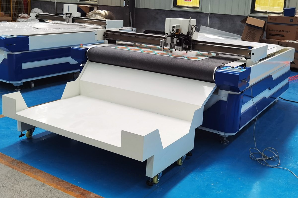
Oscillating Knife Cutting Textiles Guide
Textile cutting is a critical stage in garment manufacturing, upholstery, automotive interiors, home furnishings, technical textiles, and many other fabric-processing applications. The quality and accuracy of the cutting process directly affect material utilization, product consistency, production efficiency, and the quality of subsequent sewing or assembly operations. As manufacturers increasingly adopt digital production methods, oscillating knife cutting has become an efficient and flexible alternative to traditional manual cutting and other mechanical cutting techniques.
Oscillating knife cutting machines use a rapidly moving blade to cut textile materials according to computer-generated patterns. Unlike rotary cutting tools that rely mainly on continuous rotation, the oscillating knife moves up and down at high frequency while following a programmed cutting path. This allows the blade to penetrate and separate many soft, flexible, and multilayer materials cleanly while reducing dragging, distortion, and excessive material movement. Depending on the machine configuration, oscillating knife cutting systems can process woven fabrics, nonwoven textiles, felt, leather-like materials, composite fabrics, insulation textiles, technical fabrics, and various other flexible sheet materials.
One of the major advantages of oscillating knife cutting is its combination of precision, automation, and versatility. Digital nesting software can optimize pattern placement to reduce textile waste, while automated cutting helps maintain consistent dimensions across repeated production batches. CNC-controlled movement also makes it easier to produce complex shapes, curves, openings, notches, and customized patterns without manufacturing dedicated cutting dies.
However, successful textile cutting depends on more than simply selecting an oscillating knife cutting machine. Material properties, blade type, oscillation frequency, cutting speed, cutting depth, vacuum hold-down, nesting strategy, machine configuration, and maintenance all influence cutting performance.
This guide explains how oscillating knife cutting works for textiles, its advantages and limitations, suitable textile materials, machine configurations, important cutting parameters, common applications, operating challenges, maintenance requirements, and key factors to consider when selecting oscillating knife cutting solutions.
Table of Contents
Understand How Oscillating Knife Cutting Works
Oscillating knife cutting is a digitally controlled cutting process designed for soft, flexible, and semi-rigid materials such as textiles, fabrics, felt, leather-like materials, technical cloth, and composite sheets. Instead of relying on heat, a laser beam, or a continuously rotating blade, the system uses a sharp knife that moves rapidly up and down while following a programmed cutting path. This mechanical cutting action allows the machine to separate fibers cleanly while minimizing thermal damage, discoloration, melting, or burnt edges.
Complete oscillating knife cutting systems combine several coordinated technologies, including a high-frequency cutting head, CNC motion control, vacuum material hold-down, digital nesting software, and automated toolpath execution. The machine receives a digital cutting file, positions the cutting tool accurately over the worktable, and follows the programmed geometry at controlled speed and depth. Depending on the machine configuration, multiple tools can also be integrated for marking, creasing, punching, or other processing steps. Understanding how these components work together helps operators optimize cutting quality, productivity, material utilization, and process consistency.
Basic Working Principle of Oscillating Knives
The basic working principle of oscillating knife cutting machines is based on rapid reciprocating blade movement combined with controlled machine motion. A sharp blade is mounted in the cutting head and driven vertically or near-vertically at high frequency. While the blade oscillates, the CNC system moves the cutting head across the material according to the programmed cutting path.
As the knife penetrates the textile, its repeated up-and-down movement reduces the continuous dragging force that can occur with a static blade. This helps the blade pass through fibers more efficiently and reduces the risk of pulling, stretching, bunching, or deforming flexible materials. Because textiles can vary significantly in thickness, density, weave structure, coating, and elasticity, cutting parameters must be adjusted according to the characteristics of the material.
The machine can usually control cutting speed, blade depth, oscillation behavior, corner handling, acceleration, and other parameters. These settings allow the cutting process to be adapted for thin fabrics, thick felt, multilayer textile stacks, coated fabrics, and other flexible materials. The result is a programmable cutting process capable of producing repeated parts with consistent shapes and dimensions.
High-Frequency Blade Oscillation
High-frequency blade oscillation is one of the defining features of oscillating knife cutting. During operation, the blade moves rapidly back and forth along its cutting axis. This repeated motion creates a sawing-like mechanical action that helps the blade penetrate material fibers with less resistance than stationary cutting knives.
The frequency and stroke of the blade can significantly affect cutting performance. Higher oscillation speeds can improve cutting efficiency in dense, thick, or fibrous materials, while different blade strokes may be suitable for different material thicknesses. The correct configuration helps reduce cutting resistance and prevents excessive material movement during processing.
Blade oscillation is particularly useful for textiles that are difficult to cut cleanly with simple drag knives. Felt, technical textiles, layered fabrics, insulation materials, and dense woven products can generate considerable resistance against a static blade. Oscillation helps overcome this resistance while maintaining a relatively narrow cutting line.
However, higher oscillation frequency does not automatically produce better results in every application. Excessive cutting speed, incorrect blade geometry, insufficient vacuum hold-down, or improper cutting depth can still cause fraying, poor edge quality, incomplete cuts, or accelerated blade wear. For this reason, blade oscillation must be coordinated with the overall machine parameters.
CNC-Controlled X-Y Motion
The cutting head of oscillating knife cutting machines is typically mounted on a gantry or bridge structure capable of moving precisely along the X and Y axes. These movements are controlled by the CNC system, which converts digital toolpaths into coordinated motor commands.
The X-Y motion system determines where the blade travels across the worktable and how accurately it follows straight lines, curves, corners, and detailed contours. Servo motors, linear guide rails, drive systems, motion controllers, and positioning feedback work together to maintain smooth and repeatable movement.
Accurate CNC control is especially important when cutting textile parts that must fit together during sewing, bonding, lamination, or assembly. Even small dimensional inconsistencies may affect the quality of the finished product. Digital motion control helps maintain consistent sizes across large production batches and reduces the variation associated with manual cutting.
The CNC controller also manages acceleration and deceleration when the blade approaches corners or complex shapes. Sharp direction changes may require reduced speed to prevent material shifting or blade deflection. Advanced systems can automatically optimize motion according to toolpath geometry, helping maintain cutting accuracy without unnecessarily reducing overall productivity.
Material Positioning and Vacuum Hold-Down
Textiles are often flexible, lightweight, elastic, or easily distorted, so effective material positioning is essential. Unlike rigid panels that remain relatively stable during machining, fabrics can shift, wrinkle, lift, or stretch when exposed to cutting forces. Oscillating knife cutting systems commonly use vacuum worktables to keep materials flat and stable.
A vacuum pump generates negative pressure beneath the cutting surface. Air is drawn through a permeable cutting mat or through designated vacuum zones, creating suction that holds the textile against the table. This reduces movement while the cutting head travels across the material.
Proper vacuum hold-down improves dimensional accuracy, edge quality, and repeatability. It is particularly important for lightweight fabrics, large-format sheets, multilayer stacks, and materials with flexible surfaces. Zoned vacuum systems may concentrate suction in the active cutting area, helping improve holding force and reduce unnecessary energy consumption.
Material preparation also influences positioning. Operators should ensure that fabric is laid flat, aligned correctly, and free from excessive folds or tension. Stretching a textile too tightly during loading can cause dimensional changes after cutting, while insufficient hold-down can allow patterns to shift. Effective positioning therefore combines suitable vacuum performance with careful material handling.
Toolpath Generation From Digital Cutting Files
Oscillating knife cutting is based on digital production data. Cutting patterns are normally created in CAD software, nesting software, or other design programs and then imported into the machine control system. Common digital files contain the outlines, internal cutouts, reference marks, holes, and other geometric information required for production.
Before cutting begins, software converts these designs into machine-readable toolpaths. The toolpath specifies where the cutting head should move, which tool should be used, where the blade should enter and exit the material, and how the machine should handle corners, curves, and transitions.
Nesting software can also arrange multiple parts efficiently across the available material area. By positioning shapes close together while maintaining suitable cutting clearance, nesting helps reduce scrap and improve textile utilization. This can be especially valuable when processing expensive fabrics or producing large quantities of differently shaped components.
Toolpath optimization can also reduce unnecessary machine movement. The software may determine the most efficient sequence for cutting individual parts, minimizing non-cutting travel between contours. For automated production environments, digital files can be stored, modified, and reused, making it easier to reproduce previous jobs or switch quickly between different product designs.
Cutting, Marking, Creasing, and Other Integrated Processes
Modern oscillating knife cutting machines can perform more than simple cutting. Depending on the tool head and accessory configuration, the same CNC platform may support several processing operations within one automated workflow.
Cutting is the primary function, but marking tools can also apply reference lines, assembly indicators, identification codes, seam locations, or positioning marks directly onto textile components. These markings can simplify downstream sewing, bonding, or assembly processes.
Creasing tools may be used with foldable materials or textile-related composites where controlled fold lines are required. Some systems can also integrate punching, perforating, kiss cutting, routing, or specialized wheels for particular applications. Tool-changing systems or multi-tool heads allow the machine to switch between operations automatically according to the programmed file.
Combining multiple processes on one machine can reduce separate handling stages and improve production consistency. Instead of moving materials between different workstations for cutting and marking, several tasks can be completed during the same processing cycle. This reduces manual intervention, shortens production time, and helps maintain alignment between cutting features and reference marks.
The exact combination of tools depends on the textile application. Garment production may emphasize cutting and marking, while technical textile processing may require cutting, notching, punching, or specialized edge features. Choosing suitable tooling allows the machine to become a flexible digital production platform rather than a single-purpose cutter.
Oscillating knife cutting works through the coordinated operation of a rapidly reciprocating blade, CNC-controlled motion, secure material hold-down, and digital toolpath management. The high-frequency blade movement helps reduce cutting resistance and allows the knife to process soft, flexible, fibrous, and layered textiles without introducing heat into the material. At the same time, CNC-controlled X-Y movement ensures that the blade follows programmed shapes with repeatable accuracy.
Vacuum hold-down is essential for preventing flexible materials from shifting or wrinkling during processing, while digital cutting files provide the instructions required for toolpath generation, nesting, and automated production. Software can optimize both material usage and cutting sequence, helping reduce waste and improve overall efficiency.
The ability to integrate cutting with marking, creasing, punching, or other processes further increases the flexibility of oscillating knife cutting systems. By combining several production steps on one digital cutting platform, manufacturers can reduce manual handling, improve consistency, and simplify workflow management. The final cutting performance depends on how well the blade, motion system, vacuum table, digital files, and processing parameters are matched to the textile being processed. A clear understanding of these working principles provides the foundation for selecting appropriate equipment and achieving stable, efficient textile cutting.
Main Components of Textile Oscillating Knife Cutting Machines
Textile oscillating knife cutting machines are a coordinated digital cutting system made up of mechanical, electrical, pneumatic, vacuum, and software components. Each part contributes to cutting accuracy, material stability, production efficiency, and operator safety. The cutting head and blade perform the actual material separation, while the CNC motion system guides the tool along programmed paths. The worktable and vacuum adsorption system keep flexible textiles flat and stable, and automatic feeding and conveyor mechanisms support continuous processing of rolled materials.
At the same time, the control system and cutting software manage toolpaths, cutting parameters, nesting, material handling, and machine operation. Safety devices protect operators from moving components and help reduce the consequences of abnormal machine conditions. The performance of oscillating knife cutting machines therefore depends not only on the cutting tool itself but also on how effectively all machine components work together. Understanding the purpose of each major component helps manufacturers evaluate machine configurations, select suitable options, maintain equipment properly, and achieve reliable textile cutting results.
Oscillating Knife Cutting Head
The oscillating knife cutting head is the core processing unit responsible for driving the blade through the textile. It contains the mechanism that produces rapid reciprocating movement, allowing the knife to move up and down at high frequency while the machine follows the programmed cutting path.
Depending on the machine design, the cutting head may use electric, pneumatic, or other drive mechanisms. The oscillation frequency and stroke length are selected according to the thickness, density, flexibility, and fiber structure of the material. Thin woven fabrics may require different cutting conditions from thick felt, multilayer fabrics, insulation textiles, or technical composites.
A well-designed cutting head should provide stable oscillation, low vibration, accurate blade positioning, and reliable long-term operation. It should also allow quick blade replacement and adjustment because different textile applications may require different blade shapes and cutting depths.
Some machines use modular or multi-tool cutting heads that allow several tools to be installed together. This makes it possible to combine oscillating knife cutting with marking, creasing, punching, or other operations without requiring separate machines.
Cutting Blade and Blade Holder
The blade directly contacts the textile and is one of the most important factors affecting edge quality, cutting resistance, and productivity. Oscillating knife blades are available in different lengths, thicknesses, tip angles, edge geometries, and materials. The correct blade should be selected according to the characteristics of the textile being processed.
Sharp, narrow blades are often suitable for detailed contours and lightweight materials, while thicker or longer blades may be required for dense fabrics or multilayer stacks. Blade geometry can influence how easily the knife enters the material, how accurately it follows tight curves, and how much lateral force is generated during cutting.
The blade holder secures the knife firmly inside the cutting head and maintains the correct cutting orientation. A stable holder reduces blade movement, vibration, and deflection, helping maintain consistent dimensions throughout the cutting process.
Blade condition should be checked regularly. A dull, chipped, bent, or improperly installed blade can increase cutting resistance, produce frayed edges, cause incomplete cuts, and reduce dimensional accuracy. Regular blade replacement is therefore an important part of maintaining cutting quality.
CNC Motion System
The CNC motion system controls the precise movement of the cutting head across the worktable. It typically includes motors, drive units, linear guide rails, transmission components, position feedback devices, and CNC controllers.
During operation, the system moves the cutting head along the X and Y axes according to the digital toolpath. Some machines also control the vertical movement of the tool or additional rotational axes used to orient the blade correctly while following complex contours.
Servo motors are commonly used because they provide fast response, accurate positioning, and smooth acceleration and deceleration. High-quality guide rails and transmission systems help maintain stability during rapid movement and repeated production cycles.
Motion accuracy is especially important for textile parts that require precise alignment during sewing, bonding, or assembly. The CNC system must maintain consistent cutting dimensions while handling straight lines, curves, corners, small openings, and irregular shapes.
The controller may also automatically adjust speed around sharp corners or detailed features. This reduces blade deflection and material movement while maintaining efficient cutting speeds on longer, simpler paths.
Cutting Worktable
The cutting worktable provides the supporting surface on which textile materials are positioned and processed. It must remain flat, stable, and resistant to deformation because uneven surfaces can affect cutting depth and material positioning.
Many textile oscillating knife cutting machines use a vacuum-compatible worktable covered by a replaceable cutting mat or permeable belt. The blade passes slightly through the material and into this sacrificial surface, allowing complete separation without damaging the machine structure below.
Worktable dimensions are selected according to the size of the textile products and production requirements. Smaller fixed tables may be suitable for sheet materials or limited production batches, while larger tables and conveyor-style worktables are better suited to continuous processing and wide textile rolls.
Some machines divide the worktable into multiple vacuum zones. Operators can activate only the zones required for the current job, concentrating suction where the material is located and improving energy efficiency.
Maintaining a clean and flat cutting surface is essential. Excessive wear, debris buildup, or damaged cutting mats can reduce vacuum effectiveness and cause inconsistent cutting depth.
Vacuum Adsorption System
The vacuum adsorption system holds flexible textiles firmly against the worktable during cutting. Because fabrics can move, wrinkle, curl, or stretch easily, reliable material fixation is essential for maintaining cutting accuracy.
A vacuum pump or blower removes air from beneath the cutting surface, creating negative pressure. Air passes through small openings, a permeable cutting mat, or a conveyor belt, pulling the textile downward and keeping it flat.
Vacuum strength must be appropriate for the material being processed. Lightweight textiles may require carefully controlled suction to avoid distortion, while thicker or less permeable materials may need stronger airflow to remain stable.
Material permeability also affects adsorption performance. Highly porous fabrics allow air to pass through easily, making it more difficult to maintain strong vacuum pressure. In such cases, manufacturers may use covering films, optimized vacuum zones, or higher-capacity blowers to improve holding force.
Regular maintenance of filters, ducts, pumps, seals, and worktable surfaces is important because air leaks or blocked airflow can reduce vacuum performance and cause material movement during cutting.
Automatic Feeding System
Automatic feeding systems are commonly installed when textile materials are supplied in rolls. Its purpose is to deliver material continuously from the roll to the cutting area with controlled tension and accurate alignment.
The system typically includes a roll support, unwinding mechanism, feeding rollers, tension control devices, sensors, and synchronization components. As one section of textile is cut, the feeding system advances the next section onto the worktable.
Consistent feeding is particularly important for flexible or elastic fabrics. Excessive tension can stretch the textile and change its dimensions, while insufficient tension may create wrinkles or folds. A properly adjusted feeding system maintains a stable material condition throughout production.
Automatic feeding reduces manual loading requirements and supports long production runs. It can also improve productivity by allowing cutting and material advancement to operate as part of a coordinated workflow.
Advanced systems may include edge alignment or deviation correction functions that detect material position and automatically adjust feeding direction. This helps prevent gradual misalignment when processing long rolls.
Conveyor Belt
The conveyor belt works together with the automatic feeding system to support continuous textile cutting. Instead of using a completely stationary worktable, the machine uses a movable cutting surface that transports material through the processing area.
The belt is usually made from a durable, permeable material that allows vacuum suction to pass through while also withstanding repeated contact with the cutting blade. The knife cuts slightly into the belt surface, so the belt functions as both a transport medium and a sacrificial cutting layer.
After one section of material has been processed, the conveyor advances the cut components forward while bringing fresh material into position. This allows continuous roll-to-cut production without repeatedly stopping the machine for manual unloading and reloading.
Conveyor belt movement must be accurately synchronized with the CNC system and automatic feeder. Poor synchronization can cause material shifting, overlapping, stretching, or positioning errors.
Over time, the belt may develop grooves or worn areas due to repeated cutting. Regular inspection, cleaning, tension adjustment, and eventual replacement help maintain a flat cutting surface and reliable vacuum performance.
Control System and Software
The control system acts as the central coordinator of the oscillating knife cutting machine. It receives digital cutting data and manages tool movement, cutting parameters, vacuum operation, material feeding, conveyor movement, and auxiliary functions.
Operators typically interact with the machine through a computer, industrial touchscreen, or dedicated control panel. The interface allows them to import cutting files, select tools, set cutting speed and depth, adjust material parameters, start production, and monitor machine status.
Cutting software converts CAD designs into executable toolpaths. It may also include nesting functions that arrange parts efficiently across the available textile area. Optimized nesting can significantly reduce offcuts and improve material utilization, particularly when expensive technical fabrics or large production volumes are involved.
Advanced software may automatically optimize cutting sequence, tool selection, entry points, corner handling, and non-cutting movement. Material parameter libraries can also store suitable settings for frequently processed textiles, reducing setup time between jobs.
Reliable communication between the software, controller, motors, cutting tools, vacuum system, and feeding equipment is essential for stable automated production.
Safety Devices and Emergency Controls
Safety systems are essential because oscillating knife cutting machines contain rapidly moving cutting tools, motorized gantries, conveyor mechanisms, and electrical components. Machines should incorporate multiple protective measures to reduce the risk of operator injury and equipment damage.
Emergency stop buttons are among the most important safety components. They should be positioned where operators can reach them quickly if abnormal movement, material jams, tool breakage, or other hazards occur. Activating the emergency stop should rapidly interrupt hazardous machine motion.
Depending on the machine design, additional safety features may include protective covers, collision sensors, light curtains, safety mats, proximity sensors, warning lights, acoustic alarms, limit switches, and overtravel protection. These devices help prevent operators from entering dangerous areas while the machine is operating.
Electrical protection may include overload protection, grounding, circuit breakers, and fault monitoring. Software can also monitor operating conditions and stop the machine when abnormal parameters are detected.
Safety devices should never be bypassed for convenience. Operators should inspect emergency controls regularly and follow the manufacturer’s operating procedures, lockout requirements, and maintenance instructions.
Textile oscillating knife cutting machines rely on several interconnected systems to deliver accurate, efficient, and repeatable cutting. The oscillating knife cutting head generates the rapid blade movement required to penetrate flexible and fibrous materials, while the blade and holder determine cutting sharpness, stability, and edge quality. The CNC motion system guides the tool accurately across the worktable and controls how it follows complex digital patterns.
The cutting worktable and vacuum adsorption system keep textiles flat and stable, helping prevent wrinkles, movement, and dimensional errors. For roll-fed production, automatic feeding systems and conveyor belts support continuous operation while controlling material tension and positioning.
The control system and software connect all of these components into one automated workflow. They manage digital files, cutting parameters, nesting, toolpaths, material transport, and auxiliary operations. Safety devices and emergency controls provide an additional layer of protection for both operators and equipment.
No single component determines machine performance by itself. Cutting quality depends on the coordination of the mechanical structure, blade system, CNC motion, vacuum hold-down, feeding equipment, software, and safety controls. Selecting a machine with appropriately matched components is therefore essential for achieving consistent textile cutting quality, reliable productivity, efficient material utilization, and stable long-term operation.
Which Textiles Can Be Cut
Oscillating knife cutting machines can process a wide variety of textile materials, making them suitable for applications ranging from apparel and upholstery to automotive interiors, filtration, insulation, technical fabrics, and industrial composites. Because the blade cuts mechanically rather than thermally, the process does not create a heat-affected zone and is particularly useful for materials that could melt, discolor, burn, or release undesirable fumes when exposed to high temperatures.
However, not all textiles behave the same way during cutting. Material thickness, weave density, elasticity, surface coating, fiber orientation, porosity, and layer construction can all influence cutting quality. Some materials remain naturally flat and stable, while others may stretch, shift, compress, fray, or move under the blade. The correct blade geometry, cutting speed, oscillation frequency, vacuum strength, and material feeding method therefore need to be matched to the textile being processed.
Understanding which textiles are suitable for oscillating knife cutting helps manufacturers select appropriate machine configurations, reduce material waste, prevent edge defects, and achieve consistent cutting results across different production requirements.
Natural Fabrics
Natural fabrics are commonly cut with oscillating knife cutting systems because many of them respond well to mechanical blade cutting. Cotton, linen, wool, canvas, hemp, and other plant- or animal-based textiles can generally be processed effectively when the machine is configured correctly.
Cotton fabrics are widely used in garments, home textiles, bags, upholstery, and industrial applications. Their cutting behavior depends on weave density and fabric weight. Lightweight cotton may shift easily and therefore requires effective vacuum hold-down, while heavier cotton canvas tends to remain more stable during cutting.
Linen and hemp fabrics may have relatively coarse fiber structures, so sharp blades are important for reducing fiber pulling and frayed edges. Wool fabrics can vary considerably in thickness and density, from lightweight woven wool to thicker felted materials. Cutting speed and blade depth should be adjusted accordingly.
Natural fabrics may also be sensitive to stretching, wrinkling, and deformation during loading. Careful material placement and controlled feeding help maintain dimensional accuracy. Because oscillating knife cutting does not introduce heat, it avoids scorching or discoloration that could otherwise affect sensitive natural fibers.
Synthetic Fabrics
Synthetic fabrics such as polyester, nylon, acrylic, polypropylene, and various blended textiles can also be cut using oscillating knife cutting technology. These materials are commonly found in clothing, outdoor products, automotive interiors, industrial covers, filtration products, and technical textile applications.
Mechanical knife cutting is particularly useful when manufacturers want to avoid heat-related changes. Some synthetic fibers can melt or fuse when exposed to high temperatures, which may alter edge appearance, create hardened edges, or affect material properties. Oscillating knives cut without thermal input, helping preserve the original structure of the textile.
Synthetic fabrics can vary significantly in elasticity, slipperiness, and surface finish. Smooth or coated fabrics may move more easily across the cutting surface, requiring stronger vacuum hold-down or careful tension control. Elastic synthetic fabrics may stretch under excessive feeding or cutting forces, which can result in dimensional errors after the material relaxes.
Blade sharpness is important because dull blades can drag fibers instead of separating them cleanly. Proper parameter adjustment helps maintain consistent edge quality and accurate part geometry across repeated production runs.
Woven Textiles
Woven textiles are formed by interlacing warp and weft yarns and are among the most common materials processed with oscillating knife cutting machines. Their relatively structured construction often provides good dimensional stability, making them suitable for automated digital cutting.
The cutting behavior of woven textiles depends on yarn thickness, weave type, fiber composition, and fabric density. Tightly woven materials generally remain stable during cutting, while loosely woven fabrics may fray more easily along cut edges.
Oscillating blades can follow complex contours, internal cutouts, notches, and curved profiles without requiring physical dies. This makes digital cutting suitable for customized parts and frequently changing production designs.
For loosely woven materials, blade selection and cutting direction can influence edge quality. Excessive cutting speed may pull fibers from the weave, while an appropriately sharp blade and stable vacuum hold-down can reduce distortion.
Woven textiles can also be processed in multiple layers when machine capacity, blade length, and vacuum performance are sufficient. However, thicker stacks require careful control to ensure that the lower layers are cut completely without excessive blade deflection.
Knitted Fabrics
Knitted fabrics require special attention because their looped construction usually makes them more flexible and elastic than woven materials. Examples include jersey, rib knit, interlock, sports fabrics, stretch textiles, and various technical knitted materials.
Their elasticity can create challenges during loading, feeding, and cutting. If the fabric is stretched while being positioned on the worktable, finished parts may shrink back after cutting and no longer match the intended dimensions. For this reason, knitted materials should generally be placed in a relaxed and natural state.
Vacuum hold-down is particularly important for preventing movement during cutting. The machine should secure the fabric without creating excessive localized tension. Conveyor feeding systems should also advance the material smoothly to avoid stretching between the roll and cutting area.
Sharp blades and controlled cutting speeds help minimize fabric dragging. For highly elastic knits, manufacturers may need to test different blade geometries, vacuum settings, and cutting directions before establishing standard production parameters.
With suitable setup and material handling, oscillating knife cutting machines can cut complex knitted textile patterns accurately and repeatedly.
Nonwoven Materials
Nonwoven materials are produced by bonding or entangling fibers rather than weaving or knitting them. They are widely used in filtration, medical products, insulation, packaging, hygiene products, protective materials, and industrial applications.
Oscillating knife cutting is well suited to many nonwovens because the blade can separate fibers mechanically without adding heat. Materials such as spunbond fabrics, needle-punched nonwovens, filter media, and various synthetic fiber mats can be processed efficiently.
The density and thickness of nonwoven materials can vary greatly. Lightweight materials may be highly porous and difficult to hold with vacuum suction, while dense nonwovens may require more aggressive oscillation and stronger blades.
Porosity is an important consideration because air can pass through the material and reduce vacuum efficiency. In such cases, operators may use masking sheets, localized vacuum zones, or higher-capacity vacuum systems to improve material stability.
Some nonwovens also compress under the blade, so cutting depth must be sufficient to ensure complete separation while avoiding unnecessary wear on the cutting surface.
Felt and Technical Felt
Felt is particularly well suited to oscillating knife cutting because of its dense, fibrous structure. Both natural and synthetic felts can be processed, including wool felt, polyester felt, acoustic felt, filtration felt, polishing felt, and industrial technical felt.
Because felt does not have a conventional woven structure, it is less likely to unravel along cut edges. However, thick or dense felt can create considerable resistance against the blade. High-frequency oscillation helps the knife penetrate the fibers while reducing drag.
Blade length should be selected according to material thickness, while blade rigidity becomes increasingly important for thicker sheets. A blade that is too thin may bend or deflect, affecting edge straightness and dimensional accuracy.
Technical felts may also vary in hardness, density, and fiber composition. Some are soft and compressible, while others are stiff and compact. Cutting speed, stroke length, oscillation frequency, and blade geometry should therefore be optimized for the specific material.
Oscillating knife cutting systems can create both simple and complex felt components without requiring dies, making them suitable for prototypes, customized production, and short or medium production runs.
Coated and Laminated Textiles
Coated and laminated textiles consist of a base fabric combined with one or more surface layers, films, membranes, foams, or coatings. These materials are common in protective clothing, tarpaulins, tents, outdoor products, automotive components, upholstery, and industrial applications.
Mechanical cutting is advantageous because it avoids thermal effects that could melt coatings, separate laminated layers, or alter surface appearance. However, the blade must pass through each layer cleanly without causing delamination.
Material stiffness and thickness can vary depending on the coating system. Some coated fabrics remain flexible, while others become relatively rigid or slippery. Strong vacuum hold-down can help prevent surface movement during cutting.
Laminated textiles may require slower cutting speeds or specialized blades to maintain clean edges across all layers. If the adhesive between layers is weak, excessive blade drag can cause separation near the cut line.
Testing is often necessary to determine the best blade type, depth, and speed for multilayer constructions, particularly when different materials have significantly different mechanical properties.
Composite Textile Materials
Composite textile materials combine fibers, fabrics, foams, films, reinforcements, or other materials into a multilayer structure. They are increasingly used in automotive, aerospace, sports equipment, protective products, industrial manufacturing, and specialized technical applications.
Oscillating knife cutting can handle many of these composites, provided that the material can be mechanically separated without excessive resistance. Examples may include fabric-foam laminates, reinforced textile sheets, multilayer insulation structures, and flexible fiber composites.
Because each layer can behave differently, composite materials often require more careful parameter optimization than single-layer fabrics. A soft upper layer may compress while a dense lower layer resists the blade, increasing the possibility of incomplete cutting or blade deflection.
Blade geometry should provide enough rigidity and cutting depth to pass through the complete material thickness. Cutting speed may need to be reduced to maintain accuracy in complex contours.
Vacuum performance is also important because some composites have uneven surfaces or low permeability. Effective support and fixation help prevent layers from shifting relative to each other during cutting.
Insulation and Technical Fabrics
Insulation and technical fabrics are important applications for oscillating knife cutting because many of these materials are thick, fibrous, compressible, or sensitive to heat. Examples include thermal insulation textiles, sound-absorbing materials, fire-resistant fabrics, filter fabrics, fiberglass textiles, aramid-based materials, protective cloth, and other engineered textile products.
These materials are often designed for specific functional properties rather than appearance, which means their structure can differ significantly from conventional apparel fabrics. Some technical textiles are extremely dense, while others are lightweight and porous.
Oscillating knife cutting provides flexibility for producing irregular shapes, holes, cutouts, and custom profiles without dedicated tooling. This is valuable when technical components frequently change in size or are produced in multiple configurations.
For fibrous materials, appropriate dust extraction or protective measures may be required depending on the material composition. Operators should follow relevant safety guidance when cutting materials that generate loose fibers or dust.
Harder technical textiles may require stronger blades, slower cutting speeds, or greater oscillation force. Production testing helps identify stable settings that balance edge quality, speed, and blade life.
Difficult or Unsuitable Textile Materials
Although oscillating knife cutting systems are highly versatile, some textile materials can be difficult or unsuitable to process. Extremely loose, lightweight, or highly elastic fabrics may shift or deform even with vacuum hold-down. Materials that cannot remain flat on the worktable may also create difficulties for accurate CNC cutting.
Very thick or extremely dense textile composites may exceed the cutting head’s stroke length or blade capacity. In these cases, the knife may not penetrate the entire material thickness, or excessive resistance may cause blade bending and poor edge quality.
Highly abrasive materials can also accelerate blade wear. Certain fiber-reinforced textiles, mineral-based fabrics, or rough technical materials may require frequent blade replacement or specialized cutting tools.
Materials with sticky adhesive layers can accumulate residue on the blade, increasing friction and reducing cutting quality. Similarly, loosely bonded laminates may separate when subjected to repeated blade movement.
Some textiles may also require sealed edges to prevent fraying. Oscillating knife cutting is a cold process and therefore does not thermally seal synthetic fibers during cutting. If edge sealing is essential, an additional processing method may be required.
Before starting full production with unfamiliar textiles, manufacturers should perform test cuts to evaluate edge quality, dimensional accuracy, blade wear, vacuum holding performance, and production speed.
Oscillating knife cutting machines can process a broad range of textile materials, including natural fabrics, synthetic fabrics, woven textiles, knitted fabrics, nonwovens, felt, coated textiles, laminates, composites, insulation products, and technical fabrics. Their mechanical cutting action is especially beneficial when materials need to be processed without the melting, scorching, discoloration, or other thermal effects associated with heat-based cutting methods.
Different textile structures create different cutting challenges. Woven fabrics are generally dimensionally stable, while knitted fabrics require careful control to prevent stretching. Nonwovens and porous materials may require stronger vacuum management, and thick felt or dense composites may need more rigid blades and higher cutting force. Coated, laminated, and composite textiles require settings that prevent layer separation while ensuring complete penetration.
Not every textile is equally suitable for oscillating knife cutting. Extremely elastic, loose, abrasive, sticky, very thick, or unstable materials may require specialized tooling or alternative processing methods. Cold knife cutting also does not automatically seal the edges of synthetic textiles.
For reliable results, the material should always be evaluated together with blade geometry, oscillation settings, cutting speed, vacuum hold-down, cutting depth, feeding method, and machine capacity. Performing material-specific cutting tests before production is one of the most effective ways to establish stable parameters, reduce waste, extend blade life, and achieve consistent textile cutting quality.
Select the Right Cutting Tool and Blade
The cutting tool and blade have a direct influence on edge quality, cutting accuracy, production speed, blade life, and material stability when processing textiles with a digital cutting machine. Although oscillating knife cutting systems are highly versatile, different textile structures behave differently under mechanical cutting forces. Lightweight woven fabrics, elastic knits, dense felt, multilayer laminates, and technical textiles may each require different tools, blade geometries, cutting speeds, and oscillation characteristics.
Selecting the right tool involves more than choosing between an oscillating knife and another cutting method. Manufacturers should consider whether the material is soft or rigid, thin or thick, porous or dense, elastic or dimensionally stable, abrasive or smooth, and whether it is processed as a single layer or in a stack. Blade shape, length, thickness, tip angle, rigidity, and edge condition are equally important.
Using an unsuitable tool can lead to frayed edges, incomplete cuts, material dragging, distortion, excessive blade wear, poor corner accuracy, or reduced productivity. By matching the cutting tool and blade to the textile characteristics and required geometry, operators can improve cutting consistency, reduce downtime, and achieve more reliable production results.
Oscillating Knife Tool
The oscillating knife cutting tool is one of the most widely used cutting tools for flexible and fibrous textiles. It uses a blade that moves rapidly up and down while the cutting head follows CNC-programmed paths. This reciprocating motion helps the blade penetrate the material with less continuous drag than a stationary knife.
Oscillating knives are particularly effective for felt, woven fabrics, nonwovens, technical textiles, insulation materials, laminated fabrics, and many multilayer textile constructions. The repeated blade movement helps separate dense fibers and reduces the force required to move through thicker materials.
Another advantage is that the oscillating knife does not introduce heat into the textile. This makes it suitable for materials that could melt, discolor, harden, or release undesirable fumes when exposed to thermal cutting.
Tool performance depends on several factors, including oscillation frequency, stroke length, cutting speed, blade geometry, and material thickness. Lightweight textiles generally require less aggressive settings, while dense or thick materials may benefit from stronger oscillation and a more rigid blade.
The oscillating knife cutting tool is often the default choice when flexibility, clean mechanical cutting, and the ability to process a wide variety of textile types are important.
Driven Rotary Knife
Driven rotary knives use a circular blade that rotates continuously under motor power while moving along the programmed cutting path. Instead of reciprocating vertically, the blade rolls through the textile as it cuts.
Driven rotary knives can be particularly effective for lightweight fabrics, woven textiles, technical cloth, and materials that respond well to continuous slicing action. The rolling movement produces relatively low resistance and can support high cutting speeds on straight lines and smooth curves.
Because the blade rotates as it travels, the material experiences less pushing force than it may with some stationary cutting tools. This can help reduce distortion when cutting thin or flexible textiles. Rotary knives can also create smooth edges when the material structure is compatible with rolling blade action.
However, very tight corners or small internal features may be more difficult to produce because a circular blade has a finite radius and cannot change direction instantly. Extremely thick, dense, or fibrous materials may also be better suited to an oscillating knife, depending on the machine and blade configuration.
Driven rotary knives are therefore most suitable where fast, continuous cutting and smooth contour performance are priorities.
Pneumatic Oscillating Knife
Pneumatic oscillating knives use compressed air to drive rapid blade movement. The air-powered mechanism can generate a strong oscillating force, making this tool suitable for thick, dense, or resistant textile materials.
Pneumatic oscillating knives are often used for heavy felt, dense nonwovens, insulation fabrics, multilayer textile stacks, thick composites, and other materials that create significant resistance against the blade. The relatively powerful stroke helps the blade penetrate deep or compact structures more effectively.
One of the advantages of pneumatic operation is its ability to provide strong cutting action without placing excessive load on a small electric actuator. This can be beneficial in demanding industrial applications where thick materials are processed frequently.
However, pneumatic systems require a stable compressed-air supply. Air pressure, cleanliness, and moisture control can affect tool reliability and performance. Additional maintenance may also be required for air hoses, seals, fittings, and pneumatic components.
Pneumatic oscillating knives can produce more vibration and noise than some electric systems, depending on the design. They are best selected when cutting force and penetration capacity are more important than ultra-light tool construction or minimal infrastructure requirements.
Electric Oscillating Knife
Electric oscillating knives use an electric motor or electromagnetic drive to generate high-frequency blade movement. It is one of the most common tool types used on modern digital textile cutting systems because of its precise control, relatively simple installation, and broad material compatibility.
Electric oscillating knives are suitable for many fabrics, nonwovens, felts, coated textiles, and flexible composites. Their oscillation characteristics can often be controlled consistently, allowing operators to match cutting behavior to different materials.
Compared with pneumatic designs, electric tools do not require an external compressed-air supply for blade oscillation. This can simplify machine installation and reduce dependence on additional air-processing equipment.
Electric oscillating tools can also provide fast response and stable operation during detailed contour cutting. This makes them useful for applications requiring complex shapes, frequent direction changes, or high repeatability.
However, the maximum cutting force and stroke length depend on the specific tool design. Extremely thick or resistant materials may require a more powerful electric tool or a pneumatic alternative.
For general textile cutting, electric oscillating knives offer a good balance of speed, precision, versatility, and ease of operation.
Drag Knife
A drag knife uses a stationary blade that is pulled through the material as the cutting head moves. Unlike an oscillating knife, it does not use powered reciprocating motion. The blade is typically mounted so that it aligns itself with the direction of travel.
Drag knives are simple, lightweight, and efficient for relatively thin and easy-to-cut materials. They can be used for certain fabrics, thin flexible sheets, films, paper-backed textiles, and other low-resistance materials.
Because there is no powered oscillation mechanism, drag knives usually have lower mechanical complexity and can operate quickly on suitable materials. They may also be useful for kiss cutting, where only the upper layer is cut without penetrating the backing material.
However, drag knives create a continuous pulling force. On soft, elastic, thick, or loosely woven textiles, this can cause material movement, stretching, fiber pulling, or distorted corners. They are therefore less suitable for dense felt, multilayer fabrics, and resistant technical textiles.
Corner quality can also be affected because the blade needs space to rotate into the new cutting direction. Software compensation may be used to improve corner accuracy.
A drag knife is most appropriate when the material is thin, dimensionally stable, and easy to separate mechanically.
V-Cut and Specialized Cutting Tools
V-cut tools are designed to create angled cuts rather than simple vertical edges. They are commonly used when a textile-related composite, foam-backed fabric, acoustic panel, or layered material needs beveled edges, folding grooves, or specific edge geometry.
The blade is positioned at an angle so that it cuts into the material from the side. By controlling the blade orientation and cutting depth, the machine can produce V-shaped grooves or angled edge profiles.
Specialized cutting tools may also include kiss-cutting tools, punching tools, perforating tools, creasing wheels, rotary tools, and specialized blades designed for particular materials or applications. These tools expand the capabilities of the digital cutting machine beyond standard contour cutting.
For example, a kiss-cutting tool can cut through a textile or film layer without cutting through the carrier underneath. Perforation tools can create controlled tear lines, while creasing tools may form fold references in laminated or composite products.
The need for specialized tooling depends on the final component design. Manufacturers should evaluate whether the job requires only full-depth separation or additional operations such as beveling, scoring, marking, notching, or partial-depth cutting.
Choosing Blade Shape
Blade shape strongly affects cutting performance because it determines how the knife enters the material, how easily it follows curves, and how much resistance it generates.
Sharp-pointed blades are often suitable for detailed contours, small radii, and precise entry points. Their narrow tips allow them to change direction with relatively little interference from surrounding material.
Blades with larger cutting angles or more robust profiles are better suited to thick and dense materials because they provide greater strength and resistance to bending. However, a wider blade may create more resistance and may be less suitable for intricate details.
Single-edge blades are commonly used for general textile cutting. Double-edge or specially ground blades may be used for particular tool designs or material structures.
The shape of the blade tip also affects piercing behavior. A narrow, pointed tip can penetrate lightweight or layered textiles more easily, while a stronger tip may be preferred when repeatedly entering dense felt or composite materials.
Blade selection should therefore balance sharpness, strength, turning ability, and wear resistance. A blade that performs very well on straight cuts may not necessarily be the best option for tight corners or small internal details.
Choosing Blade Length and Thickness
Blade length should be matched to the thickness of the textile or stack being processed. The cutting edge must extend far enough to penetrate the entire material while still providing sufficient clearance and stable support in the blade holder.
If the blade is too short, the lower layers may remain partially uncut. This can lead to manual separation, damaged edges, or rejected components. If the blade is unnecessarily long, it may become more flexible and prone to deflection during high-speed cutting.
Blade thickness also influences rigidity and cutting resistance. Thin blades can produce precise contours and generate relatively low resistance, making them suitable for lightweight or detailed work. However, they can bend more easily when cutting thick or dense materials.
Thicker blades provide greater stiffness and are more suitable for heavy felt, thick nonwovens, insulation fabrics, and multilayer stacks. Their increased strength helps maintain vertical edge accuracy, but they may require greater cutting force and can be less effective in very tight curves.
The ideal blade should be long enough to cut through the material but no longer than necessary. Thickness should provide sufficient rigidity without creating excessive cutting resistance.
Selecting a Blade According to Textile Type
Blade selection should always reflect the physical characteristics of the textile rather than relying on one blade for every job.
Lightweight woven fabrics generally benefit from sharp, thin blades that minimize pulling force. Because these materials can move easily, clean penetration and low cutting resistance are important.
Knitted and elastic fabrics require blades that separate fibers cleanly without dragging or stretching the material. Sharpness is critical, and cutting speed may need to be reduced for highly elastic structures.
Dense felt and technical felt often require longer, thicker, and more rigid blades. High-frequency oscillation combined with a robust blade helps overcome the resistance created by compact fiber structures.
Nonwoven materials vary widely. Soft, lightweight nonwovens may require thin blades and strong vacuum fixation, while dense needle-punched materials may need stronger blades and greater cutting force.
Coated and laminated textiles should be cut with blades that minimize layer separation. A clean, sharp edge helps reduce pulling between layers, while suitable cutting speed prevents excessive friction.
Composite textile materials often require blade testing because different layers may have different hardness and resistance. The selected blade must be capable of penetrating the complete construction without excessive bending or delamination.
For abrasive technical fabrics, blade wear resistance becomes more important. More durable blade materials or more frequent replacement may be necessary.
Recognizing When a Blade Needs Replacement
Blade condition has a major impact on textile cutting quality. Even if the machine, software, and vacuum system are operating correctly, a worn blade can produce poor results.
One of the clearest signs of blade wear is increasing edge fraying. As the cutting edge becomes dull, it may pull fibers instead of separating them cleanly. This can leave fuzzy, uneven, or damaged edges.
Incomplete cutting is another warning sign. If the blade no longer penetrates the full material thickness at settings that previously worked correctly, the cutting edge may have become dull or damaged.
Operators may also notice increased cutting resistance, material dragging, or higher vibration. The machine may need to slow down to maintain the same quality, indicating that the blade is no longer cutting efficiently.
Visual inspection can reveal chipped tips, bent blades, worn edges, or adhesive buildup. Sticky coatings or laminated materials can deposit residue on the blade and reduce cutting effectiveness even when the edge itself is still relatively sharp.
Blade replacement should not be delayed until cutting quality becomes unacceptable. Regular inspection and preventive replacement can reduce scrap, improve dimensional consistency, and prevent excessive load on the cutting head.
Selecting the right cutting tool and blade is essential for achieving reliable results in textile oscillating knife cutting. Oscillating knives provide versatile mechanical cutting for a wide range of fabrics, while driven rotary knives can offer fast, smooth cutting on suitable lightweight materials. Pneumatic oscillating knives provide strong cutting force for thick and dense textiles, whereas electric oscillating knives offer precise, flexible performance for many general-purpose applications. Drag knives are useful for thin, low-resistance materials, and V-cut or specialized tools can add beveling, scoring, kiss cutting, perforation, and other processing capabilities.
Blade geometry is equally important. Shape affects penetration and contour accuracy, while blade length must match material thickness. Blade thickness determines the balance between rigidity and cutting resistance. Lightweight, elastic, dense, laminated, abrasive, and multilayer textiles may all require different blade configurations.
Tool and blade selection should therefore be based on textile type, thickness, density, elasticity, layer construction, required contour complexity, and production speed. Operators should also monitor blade condition carefully. Fraying, incomplete cuts, increased resistance, vibration, material dragging, and visible edge damage are common indications that replacement is required.
By combining the correct cutting tool with the appropriate blade shape, length, thickness, and maintenance schedule, manufacturers can improve edge quality, reduce material distortion, extend machine component life, and maintain consistent cutting performance across a wide range of textile applications.
Prepare Textile Materials Before Cutting
Proper material preparation is one of the most important steps in achieving accurate and repeatable results with oscillating knife cutting machines. Even highly precise CNC cutting systems cannot fully compensate for textiles that are wrinkled, stretched, misaligned, unevenly layered, or poorly positioned. Because fabrics are flexible and can easily shift or deform, their condition before cutting directly affects dimensional accuracy, edge quality, pattern matching, material utilization, and downstream sewing or assembly.
Preparation requirements vary according to textile structure, elasticity, thickness, surface finish, roll condition, and production method. Woven fabrics may require careful grain alignment, while knitted materials often need sufficient relaxation to release stored tension. Printed fabrics may require visual or camera-assisted positioning, and lightweight materials may need additional vacuum support to remain stable. Roll-fed production introduces further considerations related to tension, edge alignment, and automatic feeding.
A consistent preparation procedure helps reduce cutting defects, prevent material waste, and improve production efficiency. Before starting the cutting cycle, operators should inspect the textile, allow it to stabilize where necessary, remove wrinkles, confirm orientation, choose an appropriate layering method, and ensure that the material is securely positioned on the cutting surface.
Inspect Fabric for Defects
Textile inspection should be completed before the material is placed on the cutting table. Defects that are overlooked during preparation can become part of finished components and may result in rejected products, rework, or unnecessary material loss.
Operators should look for holes, stains, tears, loose yarns, weaving defects, color variations, coating damage, uneven edges, creases, surface contamination, and other visible abnormalities. Rolled textiles should also be checked for damaged sections caused by transportation, storage, or excessive winding pressure.
For technical textiles and laminated materials, inspection should include signs of delamination, bubbles, surface cracks, inconsistent coating thickness, or areas where different layers have shifted relative to one another. These defects may affect both cutting performance and final product quality.
When defects are identified, their locations can be marked or entered into the nesting system so that cutting patterns are positioned around them. In automated production environments, vision systems may also help detect certain surface irregularities.
Early inspection prevents valuable cutting time from being spent on unusable material and allows operators to plan nesting more efficiently.
Allow Materials to Relax Before Cutting
Many textiles develop internal tension while being rolled, stretched, transported, or stored. If the fabric is cut immediately after being unrolled, it may later contract, expand, curl, or change shape as these stresses are released.
Allowing the textile to relax before cutting helps it return closer to its natural dimensions. This is particularly important for knitted fabrics, elastic textiles, stretch blends, and materials that have been tightly wound on rolls.
Relaxation may involve unrolling the fabric and laying it flat for a suitable period before production. The required time depends on material composition, elasticity, roll tension, thickness, and environmental conditions. Highly elastic fabrics may require more time than stable woven materials.
Temperature and humidity can also influence textile dimensions. When materials are moved between storage areas and production environments with significantly different conditions, allowing them to acclimatize can improve dimensional consistency.
Cutting a textile while it is under stored tension can produce components that appear correct on the machine but change size after removal from the worktable. Adequate relaxation therefore helps improve final dimensional accuracy.
Control Fabric Tension
Fabric tension should remain as low and uniform as practical during loading, feeding, and cutting. Excessive tension can stretch the textile and alter its dimensions, while insufficient or uneven control can produce slack areas, folds, and inconsistent positioning.
This issue is especially important for elastic knitted fabrics and flexible technical textiles. If one side of the material is pulled more tightly than the other, components may become distorted even though the CNC cutting path itself is accurate.
For manually loaded materials, operators should avoid pulling the fabric tightly across the table. It should be positioned smoothly in its natural state and then held in place by the vacuum system.
In roll-fed systems, unwinding devices and tension controls should be adjusted so that material enters the cutting area evenly. Feed rollers should not stretch the textile as they move it forward.
Consistent tension also improves repeatability between batches. Once appropriate settings have been established for a particular material, they should be documented and reused whenever similar rolls are processed.
Remove Wrinkles and Folds
Wrinkles, folds, and raised areas should be removed before the cutting cycle begins. When a textile does not lie flat, the effective cutting depth changes and the blade may cut an inaccurate shape or fail to penetrate the material completely.
Wrinkles can also cause the fabric to shift as the cutting head passes over them. In multilayer stacks, folds may create uneven layer thickness and produce inconsistent dimensions between the upper and lower pieces.
Operators should spread the textile smoothly across the worktable without overstretching it. Light manual smoothing, rollers, controlled feeding, or other appropriate methods can be used depending on the material.
Vacuum adsorption helps flatten many fabrics after they are positioned, but it should not be expected to correct severe folds or badly loaded material. Excessive wrinkles should be removed before vacuum suction is activated.
Materials that have retained strong creases from storage may need additional conditioning before cutting. The preparation method should always be compatible with the textile so that attempts to flatten it do not damage coatings, fibers, or surface finishes.
Align the Grain or Weave Direction
Grain or weave direction is important for many textile components because fabric properties can differ depending on orientation. Woven materials contain warp and weft yarns, and the amount of stretch, stiffness, drape, and dimensional stability may vary between these directions.
Cutting components at the wrong orientation can affect how they behave during sewing, assembly, or use. Apparel parts, upholstery sections, reinforcement layers, and technical textile components may all require specific grain alignment.
Before cutting, operators should identify the primary fabric direction and position the material according to the design specifications. Digital nesting files should also maintain the required part orientation rather than rotating pieces purely to maximize material utilization.
Some applications allow limited rotation to reduce waste, while others require all components to follow the same fiber direction. These restrictions should be defined during CAD and nesting preparation.
For fabrics with visible textures, directional surfaces, or mechanical properties that change with orientation, accurate grain alignment becomes even more important. Consistent alignment helps ensure that finished products have a uniform appearance and performance.
Position Printed or Patterned Fabrics Correctly
Printed and patterned textiles require additional positioning control because the location of the cut must often correspond to specific visual features. Stripes, checks, logos, decorative graphics, repeating patterns, and digitally printed designs may all need to align with the geometry of the finished component.
Before cutting, the fabric should be positioned so that the pattern reference points correspond to the digital design. Manual alignment may be sufficient for simple patterns, while more advanced applications can use camera-based vision systems.
Vision systems can identify registration marks, printed contours, pattern features, or reference points and automatically adjust the cutting path. This helps compensate for printing distortion, material stretching, or small placement differences.
Pattern matching is especially important when multiple textile components will later be joined together. Misaligned stripes or graphics can make an otherwise accurately cut product look defective.
Operators should also consider pattern repeat when creating the nesting layout. Maximizing material utilization should not override required visual alignment. In patterned textile cutting, accuracy often involves both dimensional precision and correct graphic positioning.
Determine Whether Single-Layer or Multi-Layer Cutting Is Appropriate
Before production begins, manufacturers should decide whether the textile should be cut as a single layer or in a multilayer stack. The best method depends on material characteristics, production volume, machine capability, blade length, and required accuracy.
Single-layer cutting provides excellent control over individual pieces and is especially suitable for patterned fabrics, customized production, prototypes, highly elastic textiles, and materials that are difficult to stack evenly. It also makes defect avoidance and vision-based cutting easier.
Multi-layer cutting can significantly increase productivity because several identical pieces are produced in one cutting cycle. It is commonly used when large quantities of the same components are required.
However, stacking introduces additional challenges. Layers can shift relative to one another, and thick stacks increase resistance against the blade. Excessive stack height may cause blade deflection or incomplete cutting in lower layers.
Vacuum strength, blade rigidity, cutting depth, and oscillation force must therefore be sufficient for the stack thickness. Operators should test multilayer configurations before full production and verify that parts from both the top and bottom layers meet dimensional requirements.
Secure Lightweight or Flexible Fabrics
Lightweight fabrics can be difficult to stabilize because they may move in response to cutting forces, airflow, static electricity, or machine acceleration. Very flexible or porous textiles can also reduce the effectiveness of vacuum adsorption.
The primary method of securing these materials is usually the vacuum hold-down system. The textile should be spread flat over the active vacuum area, and unused table zones may be covered where appropriate to concentrate suction.
For highly porous materials, additional covering films or other approved techniques may help improve vacuum effectiveness by reducing uncontrolled air leakage.
Operators should also minimize unnecessary airflow around the worktable. Strong ventilation or nearby fans can move very lightweight textiles before cutting begins.
Flexible materials should not be secured by applying excessive mechanical tension because this can distort the final dimensions. The goal is to hold the fabric in its natural, relaxed state while preventing lateral movement.
When cutting particularly unstable textiles, lower acceleration, optimized toolpaths, sharp blades, and reduced cutting speed may further help maintain material position.
Prepare Rolls for Automatic Feeding
Roll-fed production requires careful preparation to ensure that textiles enter the cutting area smoothly and consistently. A poorly mounted or uneven roll can cause misalignment, wrinkles, tension variation, and feed interruptions during continuous operation.
The roll should first be inspected for damage, telescoping, loose winding, crushed edges, or uneven tension. It should then be installed centrally on the feeding system with the correct unwinding direction.
Roll supports, shafts, or pneumatic chucks should securely hold the core while allowing controlled rotation. The textile should be threaded through the feeding system according to the machine manufacturer’s specified path.
Edge alignment should be checked before automatic feeding begins. If the material starts at an angle, the deviation can become larger as more fabric is advanced. Machines equipped with edge sensors or automatic correction systems should be properly calibrated.
Feeding tension must also be adjusted carefully. Excessive resistance from the roll can stretch the fabric, while uncontrolled unwinding can create slack and folds.
Before starting full production, operators should advance a short length of material through the system and confirm that feeding, conveyor movement, vacuum hold-down, and edge alignment are working together correctly.
Preparing textile materials correctly before oscillating knife cutting is essential for maintaining dimensional accuracy, cutting quality, material utilization, and production consistency. Preparation begins with inspecting the fabric for defects and identifying areas that should be excluded from the nesting layout. Materials that contain stored tension should be allowed to relax before cutting so that components do not change size after they are removed from the table.
Fabric tension should remain controlled and uniform, while wrinkles, folds, and uneven areas should be eliminated before vacuum hold-down is applied. Woven materials should be aligned according to grain or weave direction, and printed or patterned fabrics may require precise registration to ensure that visual features match the finished component.
Manufacturers should also determine whether single-layer or multilayer cutting provides the best balance of productivity and accuracy. Lightweight and flexible textiles require effective stabilization without excessive stretching, while roll-fed materials must be mounted, aligned, tensioned, and threaded correctly for automatic feeding.
A well-prepared textile gives the cutting system a stable and predictable starting condition. By combining careful inspection, relaxation, tension control, alignment, secure positioning, and proper roll preparation, operators can reduce defects, prevent material distortion, minimize waste, and achieve more consistent oscillating knife cutting results.
Prepare Digital Cutting Files and Patterns
Accurate digital files are the foundation of successful oscillating knife textile cutting. Even when the machine is mechanically precise and the material is prepared correctly, poorly constructed CAD files can cause dimensional errors, unnecessary tool movement, incomplete contours, double cutting, incorrect markings, and wasted material. Before production begins, digital patterns should therefore be checked, cleaned, organized, and converted into a form that the cutting system can interpret reliably.
The preparation process typically includes creating or importing CAD geometry, verifying dimensions, removing duplicate lines, closing open contours, assigning operations to separate layers, and defining the correct cutting sequence. Reference features such as notches, drill marks, registration points, and assembly indicators should also be added where required. In some applications, the digital design may need compensation for blade width, material compression, stretch, shrinkage, or other textile behavior.
Well-prepared cutting files make machine operation more efficient and predictable. They reduce manual adjustments, help maintain consistent part geometry, and allow nesting and automation software to work more effectively. Establishing a standard digital file preparation procedure is therefore an important step in improving cutting accuracy, productivity, and repeatability.
Create or Import CAD Designs
Digital cutting patterns can be created directly in CAD software or imported from existing design, pattern-making, or product development systems. The geometry should accurately represent the final shape, dimensions, openings, internal features, and reference marks required for each textile component.
For apparel, upholstery, automotive interiors, technical textiles, and similar applications, designs may originate from specialized pattern-making software. Industrial components may instead be created in general CAD platforms and then transferred to the cutter’s nesting or control software.
When importing existing files, operators should confirm that the geometry has not been altered during conversion. Scale, units, curves, and layer information should all be checked before the file is approved for cutting.
Clean CAD geometry is especially important when cutting detailed contours. Unnecessary points, broken curves, or excessive segmentation can cause the cutting head to slow down, hesitate, or generate rough motion. Simplifying geometry where appropriate can improve tool movement while preserving the required part shape.
Use Common Supported File Formats
Oscillating knife cutting systems typically support a variety of two-dimensional vector file formats. Common examples may include DXF, DWG, AI, EPS, PLT, SVG, and other formats depending on the machine software.
The most suitable format should preserve the original geometry, scale, units, curves, and layer information without introducing conversion errors. DXF is widely used for transferring CAD-based cutting patterns because it is compatible with many design and nesting programs.
Before selecting a format, users should verify which versions and file types are supported by the specific cutting software. Some programs may accept a format but interpret splines, text, blocks, or compound objects differently.
Raster image formats such as JPG or PNG do not normally contain true vector cutting paths unless they are first traced or converted. For accurate CNC cutting, the system generally requires vector geometry that defines the exact path of the blade.
Whenever files are exchanged between different software platforms, a test import should be performed. Operators should check the resulting dimensions and geometry before using the file for production.
Check Pattern Dimensions
Pattern dimensions should always be verified before nesting or cutting. Incorrect scaling is one of the most common digital preparation errors and can result from mismatched units, export settings, or file conversion.
Operators should confirm critical lengths, widths, diameters, hole positions, seam allowances, and other reference dimensions against the original design specifications. It is good practice to measure several known features rather than relying on only one overall dimension.
The units used in the CAD file should also match the cutting software. A drawing created in millimeters but interpreted as inches, or vice versa, can produce major scaling errors.
For parts that must fit together, related components should be checked as a complete set. Matching edges, assembly points, notches, and reference positions should align correctly before production.
Dimension verification is particularly important when files come from customers, subcontractors, or external design software. A short review before cutting can prevent large quantities of incorrectly sized components from being produced.
Remove Duplicate or Overlapping Lines
Duplicate and overlapping lines should be removed from the cutting file because they can cause the machine to cut the same path more than once. Double cutting wastes time, accelerates blade wear, damages the cutting mat, and may create poor edge quality.
Duplicate geometry often appears during CAD editing, copying, importing, or combining files from multiple sources. Two lines may occupy the same position and be difficult to detect visually.
Partially overlapping segments can cause similar problems. The cutting head may reverse direction unexpectedly, repeat part of a contour, or create unnecessary tool movements.
CAD cleanup tools can help identify and remove duplicates, while close inspection at high zoom levels may reveal small overlapping segments. Automated nesting or preprocessing software may also provide geometry validation functions.
The goal is to ensure that every required edge is represented by one continuous cutting path unless repeated cutting is intentionally required for a specific process.
Close Open Contours
Closed contours are important because most cutting software uses them to identify complete parts, holes, and internal features. If a contour contains even a very small gap, the system may not recognize it correctly.
Open contours can result in incomplete cuts, incorrect nesting, unexpected toolpaths, or failure to identify inside and outside geometry. Small gaps are especially common where line segments, arcs, or imported curves are joined.
Operators should inspect all part boundaries and use CAD tools to join endpoints where necessary. The connection tolerance should be appropriate so that nearby but unrelated geometry is not accidentally merged.
Internal holes and cutouts should also form closed loops. If a component intentionally contains an open cut, this should be clearly defined as a separate operation rather than left as an accidental gap.
Ensuring that contours are properly closed helps the software calculate cutting order, nesting boundaries, compensation, and part separation more reliably.
Define Cutting and Marking Layers
Different machine operations should be organized into clearly defined CAD layers or process categories. For example, full-depth cutting, marking, creasing, perforating, drilling, and reference points should not all be treated as identical geometry.
Layer organization allows the machine software to assign the correct tool, speed, depth, and processing method to each feature. A line intended only as a sewing reference should not be processed as a full cut, while an internal opening should not be treated as a marking line.
Consistent layer naming can simplify workflow, particularly when many jobs are processed regularly. Manufacturers may establish standard names for cut lines, marks, creases, holes, and other operations.
When files are imported, layer assignments should be reviewed because some formats may merge, rename, or remove layer information. Operators should confirm that each geometry type is linked to the correct physical tool before starting the machine.
Proper layer definition reduces setup errors and supports automated multi-tool processing.
Set Cutting Sequence
Cutting sequence determines the order in which the machine processes individual contours and parts. An optimized sequence can reduce non-cutting travel, prevent material movement, and improve overall cycle time.
Internal features such as holes and slots are generally cut before the outer contour of a part. If the outside shape is cut first, the component may become loose and shift before its internal features are completed.
The cutting sequence should also minimize long movements between distant areas of the worktable. Nesting or CAM software can automatically optimize toolpaths to reduce unnecessary travel.
For lightweight textiles, sequence planning can help maintain material stability. Cutting nearby features in a controlled order may reduce the chance that partially separated sections move under the vacuum system.
When multiple tools are used, the sequence should also reduce excessive tool changes. For example, the system may complete all marking operations before switching to the cutting knife.
A carefully planned cutting sequence improves both productivity and cutting reliability.
Add Notches, Drill Marks, and Reference Points
Notches, drill marks, reference points, and registration features can provide important information for downstream sewing, assembly, positioning, or quality control.
Notches are often used to indicate where two textile components should align during sewing. They must be accurately positioned and sized so that they remain visible without weakening or damaging the material unnecessarily.
Drill marks or point references may indicate attachment locations, button positions, fastener points, centerlines, or assembly features. Depending on the machine, these marks can be produced by punching, marking pens, inkjet tools, or specialized cutting operations.
Registration points are particularly useful when processing printed or patterned fabrics. Vision systems may use them to align digital cutting paths with printed graphics or other visible features.
These reference elements should be clearly separated from the main cutting geometry in the digital file. Their size and processing method should also be appropriate for the textile so that they remain useful during later production stages.
Compensate for Blade Width and Material Behavior
Digital patterns may require compensation for the physical characteristics of both the cutting tool and the textile. Although knife blades are very thin, they still have measurable width and geometry that can affect the final cut path in precision applications.
Tool compensation can offset the cutting path so that the finished component matches the intended dimensions. The required offset depends on blade type, thickness, orientation, and the way the tool turns around corners.
Material behavior can also influence final dimensions. Elastic textiles may stretch during feeding or cutting and then contract afterward. Compressible materials may deform under vacuum pressure, while some fabrics can shrink or expand depending on tension, temperature, or humidity.
Multilayer stacks may require additional consideration because lower layers can shift slightly or experience blade deflection. Coated or laminated textiles may also respond differently from simple single-layer fabrics.
Compensation values should ideally be established through test cutting and measurement rather than guesswork. Once suitable values have been confirmed for a specific material and blade combination, they can be saved as production parameters for future jobs.
Preparing digital cutting files correctly is essential for accurate and efficient oscillating knife textile cutting. The process begins with creating or importing clean CAD geometry in a compatible vector format and verifying that dimensions, scale, and units match the production requirements. Duplicate lines, overlapping geometry, and open contours should be corrected before the file reaches the machine.
Different operations should be assigned to appropriate layers so that cutting, marking, creasing, punching, and other processes are handled by the correct tools. The cutting sequence should be optimized to complete internal features before external contours, minimize unnecessary travel, reduce tool changes, and maintain material stability.
Notches, drill marks, registration points, and other reference features should be accurately positioned to support downstream assembly and alignment. Blade width, blade orientation, material elasticity, compression, shrinkage, and multilayer behavior may also require digital compensation.
A carefully prepared file reduces the likelihood of production errors and allows the CNC system, nesting software, cutting tools, and material handling system to operate more effectively. By combining clean CAD geometry, correct process assignments, optimized toolpaths, accurate reference features, and tested compensation values, manufacturers can achieve more consistent part dimensions, faster cutting cycles, lower material waste, and more reliable textile production.
Optimize Textile Nesting and Material Utilization
Efficient nesting is one of the most important factors in reducing textile waste and improving the overall economics of oscillating knife cutting. Nesting refers to the arrangement of multiple cutting patterns within the available material area so that parts can be produced with minimal unused space. Good nesting improves material utilization, reduces scrap, shortens production time, and can lower the cost per finished component.
Textile nesting is more complex than simply placing shapes as closely together as possible. Fabric direction, pattern orientation, visual matching, stretch behavior, cutting sequence, tool clearance, and roll dimensions must all be considered. Some parts can be freely rotated to fill unused spaces, while others must maintain a fixed orientation because of grain direction, surface texture, printed graphics, or functional requirements.
Modern nesting software can automatically analyze part geometry and generate efficient layouts, but operator knowledge is still important. The best layout should balance material savings with stable cutting, practical unloading, and efficient machine movement. By combining accurate digital patterns, appropriate nesting rules, and optimized cutting strategies, manufacturers can significantly improve textile utilization while maintaining quality and productivity.
Understand Textile Nesting
Textile nesting is the process of arranging digital cutting patterns within a defined fabric area before cutting begins. The goal is to fit the required parts into the smallest practical amount of material while respecting production constraints.
The nesting area may represent a fixed sheet, a section of roll material, or the active cutting zone of a conveyor machine. Each part is positioned according to its shape, dimensions, orientation restrictions, spacing requirements, and production quantity.
Simple rectangular parts are relatively easy to arrange efficiently, while irregular shapes can create narrow gaps and unused spaces. Good nesting software attempts to fill these gaps by rotating or repositioning compatible parts where permitted.
However, maximum geometric density is not always the best production solution. Extremely tight arrangements may increase the risk of material movement, reduce vacuum hold-down, or make cut parts difficult to remove.
Effective textile nesting therefore considers both material utilization and practical cutting conditions. A well-designed layout should reduce waste without compromising edge quality, accuracy, or machine efficiency.
Manual Versus Automatic Nesting
Manual nesting involves an operator positioning parts individually within the available material area. This approach gives users direct control over orientation, grouping, and placement and can be useful for simple jobs, small quantities, or unusual production requirements.
Experienced operators may create efficient layouts when there are only a few part shapes. Manual placement is also useful when defects must be avoided or when certain components need to be grouped for easier handling.
However, manual nesting becomes increasingly time-consuming as the number of parts and design complexity increase. Human operators may also overlook combinations that could improve material utilization.
Automatic nesting software analyzes the geometry of all required parts and calculates optimized positions within the available fabric width or sheet size. It can consider rotation limits, spacing, quantity, grain direction, and other constraints.
Automatic nesting is particularly valuable for high-volume production, mixed part sets, and irregular geometries. It reduces programming time and can generate multiple layout options quickly.
In many operations, the most effective approach combines automatic nesting with operator review. Software generates the initial layout, while the operator verifies orientation, pattern requirements, defect areas, and practical cutting conditions.
Arrange Parts According to Fabric Direction
Fabric direction must be considered during nesting because many textiles behave differently depending on the orientation of their fibers, weave, knit structure, or surface finish.
Woven fabrics have warp and weft directions that may differ in stretch, strength, drape, and dimensional stability. If components are rotated incorrectly simply to save material, the finished product may behave inconsistently during sewing, assembly, or use.
Some parts must therefore remain aligned with the fabric grain. CAD or nesting software can apply rotation restrictions so that these components are placed only in approved orientations.
Directional textiles may also include brushed fabrics, velvet-like surfaces, coated materials, or technical fabrics with different properties along specific axes. Their surface appearance or functional performance may change when orientation is reversed.
When grain direction is not critical, allowing greater rotation can improve nesting efficiency. However, orientation freedom should be determined by product requirements rather than material-saving goals alone.
Defining direction rules before automatic nesting helps ensure that software optimization does not create layouts that compromise product consistency.
Respect Pattern Matching Requirements
Printed, striped, checked, or repeating textiles require additional nesting considerations because visual features may need to align across separate components.
For example, two parts that will later be sewn together may need stripes or checks to continue smoothly across the seam. Decorative graphics may also need to appear in specific locations on finished products.
These requirements can limit where a pattern can be placed within the fabric repeat. Parts may need to be shifted away from the most material-efficient position to match specific visual reference points.
Pattern repeat dimensions should therefore be entered into the nesting process where supported. Camera-based cutting systems can also identify printed registration marks and compensate for small distortions in the textile.
For complex patterned materials, automatic nesting may be combined with vision recognition to position cutting paths relative to the actual printed image rather than relying solely on theoretical design coordinates.
Pattern matching usually reduces maximum material utilization because more space must be sacrificed to maintain visual alignment. Nevertheless, correct appearance should take priority over purely minimizing scrap when pattern continuity is part of the finished product specification.
Maintain Proper Spacing Between Parts
Spacing between nested parts should be carefully controlled. Placing components very close together can improve material utilization, but insufficient clearance may cause cutting quality or stability problems.
The required spacing depends on blade type, textile thickness, material stability, vacuum performance, and cutting sequence. If two contours are positioned too closely, the material between them may become narrow and unstable after one side is cut.
Lightweight or flexible textiles can lift, shift, or lose vacuum pressure in narrow areas. Thicker materials may require additional clearance to account for blade deflection or tool movement.
Spacing is also important when parts have sharp corners, small internal features, or complex curves. Allowing sufficient material between contours reduces the risk that one cut affects an adjacent component.
Nesting software can apply minimum spacing rules automatically. These values should be established through production testing rather than reduced excessively for the sake of achieving a higher utilization percentage.
The most efficient layout is one that minimizes unused material while still providing enough separation for reliable cutting.
Reduce Offcuts and Scrap
Reducing offcuts and scrap is a major objective of textile nesting because material often represents a significant portion of the total production cost.
Irregular parts should be arranged so that concave and convex areas fit together wherever possible. Smaller components can often be placed inside unused spaces created by larger shapes, provided that orientation and spacing rules are maintained.
Production orders can also be combined strategically. Instead of nesting each product separately, manufacturers may group compatible parts from multiple orders on the same material to fill gaps more efficiently.
Reusable remnants should be considered as well. Large offcuts left from previous jobs may be suitable for smaller components. Digital inventory systems can record remnant dimensions and make them available during future nesting.
Avoiding unnecessary margins at the edges of the material can further improve utilization, although sufficient clearance should remain for feeding, vacuum sealing, and machine operation.
Waste reduction should also be evaluated over multiple production cycles rather than one individual nest. A slightly lower utilization on one job may produce a remnant that can be reused later, while an extremely dense layout may leave only unusable small scraps.
Optimize Nesting for Roll Materials
Roll-fed textiles require nesting strategies that consider both material width and continuous feed length. Unlike fixed sheets, the nesting area can extend along the roll, allowing software to optimize part placement over a longer production section.
The priority is usually to use the available roll width efficiently. Large components can be positioned across the width, while smaller parts are used to fill remaining gaps.
Roll edge margins should be minimized without interfering with feeding, alignment, or vacuum hold-down. If material edges are uneven or damaged, a larger safety margin may be necessary.
Nesting length should also be coordinated with the machine’s cutting area and conveyor cycle. The layout may be divided into sections so that one area is cut while the next section is advanced automatically.
For long production runs, continuous nesting software can calculate new layouts as orders change or additional parts are introduced. This improves flexibility and reduces unused material between separate jobs.
Roll orientation must also remain consistent. Parts with grain restrictions or surface direction requirements should be aligned correctly along the length or width of the fabric.
Balance Material Utilization With Cutting Efficiency
The highest possible nesting percentage does not always produce the fastest or most reliable production. Extremely dense layouts may create complicated toolpaths, excessive direction changes, long cutting times, and unstable narrow waste sections.
Cutting efficiency should therefore be considered together with material utilization. Sometimes allowing slightly more spacing or rearranging parts can shorten the toolpath significantly and reduce machine movement.
Grouping similar contours may help the machine maintain higher cutting speeds. Reducing unnecessary travel between distant parts also improves productivity.
The cutting sequence should be optimized so that internal features are completed before external contours and unstable areas are not released too early. Layouts should also make finished parts easy to remove and sort.
Tool changes can influence efficiency as well. If a job includes cutting, marking, creasing, or punching, the nesting and processing sequence should minimize repeated switching between tools.
The ideal solution is not necessarily the nest with the lowest theoretical waste. It is the layout that provides a practical balance between material savings, cutting speed, edge quality, part stability, unloading convenience, and overall production cost.
Optimizing textile nesting is essential for improving material utilization and reducing production costs in oscillating knife cutting. Effective nesting arranges digital patterns within the available fabric area while considering part geometry, material direction, spacing, pattern matching, and production requirements.
Manual nesting provides flexibility and direct operator control, while automatic nesting software can quickly evaluate large numbers of parts and generate efficient layouts. In many production environments, combining automated optimization with operator review provides the best results.
Fabric grain, weave direction, surface orientation, and printed patterns must always be respected when positioning parts. Appropriate spacing should also be maintained so that closely nested contours do not create unstable material or cutting defects. Waste can be reduced by fitting irregular shapes together, combining compatible orders, reusing remnants, and minimizing unnecessary edge margins.
For roll-fed textiles, nesting should optimize both roll width and continuous length while remaining compatible with automatic feeding and conveyor operation. Most importantly, material utilization should be balanced with cutting efficiency. A slightly less dense layout may deliver faster cutting, fewer tool movements, better stability, and more reliable part quality.
By applying clear nesting rules and using suitable software, manufacturers can reduce textile consumption, limit scrap, shorten production cycles, and achieve a more efficient overall cutting process.
Set the Correct Textile Cutting Parameters
Correct cutting parameters are essential for achieving clean edges, accurate dimensions, stable material handling, and efficient production when using oscillating knife cutting machines for textiles. Even when the appropriate blade and tool have been selected, unsuitable settings can lead to fraying, incomplete cuts, material dragging, distorted corners, excessive blade wear, or unnecessary reductions in productivity. Textile properties vary considerably, so the same parameters cannot be applied successfully to every fabric.
Important settings include cutting speed, oscillation frequency, cutting depth, tool pressure, acceleration, corner speed, vacuum strength, and material feeding speed. These parameters interact with one another. For example, increasing cutting speed may require stronger material fixation, while thicker textiles may require greater cutting depth, a more rigid blade, and reduced travel speed. Lightweight or elastic fabrics often benefit from gentler acceleration and careful tension control.
Instead of selecting settings independently, operators should treat them as part of a complete cutting strategy based on fabric thickness, density, elasticity, weave structure, coating, number of layers, and required contour complexity. Test cutting should always be performed when processing a new material. Once stable settings are identified, they can be stored in a material parameter library to improve setup consistency and reduce preparation time for future production.
Cutting Speed
Cutting speed determines how quickly the cutting tool travels along the programmed toolpath. It has a direct effect on productivity, edge quality, blade load, and material stability. Higher cutting speeds can shorten cycle times, but excessive speed may prevent the blade from separating fibers completely or accurately following complex contours.
Thin and stable fabrics can often be processed at relatively high speeds because they generate limited cutting resistance. Dense felt, thick nonwovens, multilayer textiles, and reinforced technical fabrics generally require slower movement so that the blade has enough time to penetrate and separate the material.
Cutting speed should also vary according to geometry. Long straight sections can usually be processed faster than small curves, sharp corners, intricate cutouts, or narrow features. Modern CNC systems may automatically vary speed based on toolpath complexity.
Signs that cutting speed is too high include incomplete cuts, excessive fiber pulling, inaccurate corners, blade deflection, and material movement. If speed is unnecessarily low, production efficiency decreases and blade contact time may increase without improving quality.
The best setting provides the highest practical speed while maintaining clean edges, complete separation, and consistent dimensions.
Blade Oscillation Frequency
Blade oscillation frequency refers to how rapidly the oscillating knife moves back and forth during cutting. The frequency affects the blade’s ability to penetrate textile fibers and overcome resistance.
A sufficiently high oscillation frequency can improve cutting efficiency in dense, fibrous, or thick materials by creating repeated cutting actions along the blade edge. Felt, needle-punched textiles, insulation materials, and multilayer constructions may particularly benefit from strong, rapid oscillation.
Lightweight fabrics generally create less resistance and may not require the maximum available frequency. Excessive oscillation can increase vibration, blade wear, noise, and mechanical load without providing a meaningful improvement in edge quality.
Oscillation frequency should be considered together with stroke length and cutting speed. A machine moving rapidly through a dense material needs enough blade cycles along the cutting path to separate fibers consistently. Reducing travel speed may sometimes produce better results than simply maximizing oscillation frequency.
When adjustable, frequency should be optimized through test cuts. The objective is to achieve complete fiber separation with minimal material disturbance and reasonable blade life.
Cutting Depth
Cutting depth determines how far the blade penetrates through the textile and into the sacrificial cutting surface below it. Correct depth is essential because the blade must completely separate all layers without penetrating unnecessarily far into the conveyor belt or cutting mat.
If the cutting depth is too shallow, fibers may remain connected along the bottom of the material. Operators may need to separate parts manually, which can damage edges and reduce production efficiency.
Excessive cutting depth can increase blade wear, damage the cutting surface, increase resistance, and place additional load on the tool. Deep penetration may also reduce cutting accuracy because more of the blade is exposed to lateral forces.
For single-layer thin fabrics, only a small amount of penetration beyond the material thickness may be necessary. Thick felt or multilayer stacks require greater depth, but the blade should still extend only as far as needed for reliable separation.
Cutting depth should be checked whenever material thickness, layer count, blade type, or cutting surface condition changes. Automatic tool-height measurement can help maintain consistency on machines equipped with this function.
Tool Pressure
Tool pressure refers to the downward force applied by the cutting tool against the material. Depending on the tool configuration, pressure may be controlled mechanically, pneumatically, electronically, or through the vertical positioning system.
The pressure must be sufficient to maintain stable blade penetration without unnecessarily compressing or deforming the textile. Soft or compressible materials can change thickness significantly under excessive force, which may affect dimensions and edge geometry.
Lightweight textiles generally require limited downward force because they offer little cutting resistance. Dense felts, laminates, and technical textiles may require greater tool force to maintain effective blade contact.
Excessive pressure can accelerate blade and cutting-mat wear and may increase friction. Insufficient pressure can cause incomplete cuts, especially when the material surface is uneven.
Pressure requirements should therefore be determined according to material density, thickness, compressibility, blade design, and cutting speed. When changing to a substantially different textile, operators should verify the pressure rather than assuming that the previous setting remains suitable.
Acceleration and Deceleration
Acceleration and deceleration control how quickly the cutting head reaches or leaves its programmed travel speed. These settings have a major influence on both productivity and material stability.
High acceleration allows the machine to reach cutting speed quickly, which can reduce cycle times on layouts containing many short movements. However, sudden changes in motion create greater inertial forces and may cause flexible textiles to shift, stretch, or lift from the cutting surface.
Lightweight, slippery, elastic, or poorly supported fabrics generally benefit from smoother acceleration and deceleration. Thick or well-secured materials may tolerate more aggressive motion settings.
Mechanical performance must also be considered. Excessive acceleration can place additional loads on motors, guide rails, belts, racks, and other motion components.
Complex patterns with many short segments may never reach the maximum programmed cutting speed because the machine constantly accelerates and decelerates. In these situations, optimizing acceleration can have a greater effect on cycle time than increasing the maximum cutting speed.
Suitable settings should provide smooth movement while preserving part accuracy and maintaining stable material positioning.
Corner Speed
Corner speed controls how quickly the cutting head moves through sharp turns, small curves, and rapid direction changes. It is especially important for maintaining accurate geometry in textile parts with detailed contours.
If the tool enters a sharp corner at excessive speed, the blade may bend, drag the fabric, or create a rounded corner instead of following the intended geometry. Flexible materials can also shift because of sudden directional forces.
Reducing speed near corners gives the blade more time to rotate or realign with the cutting direction. This is particularly important for thick materials, long blades, and drag-type tools because they are more sensitive to turning forces.
However, corner speed should not be unnecessarily low. Frequent severe slowdowns can substantially increase total cycle time when a pattern contains many small features.
Advanced cutting software can automatically adjust velocity according to corner angle, curve radius, and tool characteristics. Operators should use these functions where available and refine them based on test results.
The goal is to maintain crisp, dimensionally accurate corners while avoiding excessive reductions in overall cutting efficiency.
Vacuum Strength
Vacuum strength determines how securely the textile is held against the cutting surface. Effective hold-down prevents shifting, wrinkling, lifting, and stretching while the blade follows the programmed path.
Insufficient vacuum can cause dimensional errors even when all other cutting parameters are correct. Lightweight fabrics may move with the cutting head, while small components can become loose after their outer contours are completed.
Vacuum requirements depend strongly on material permeability. Dense, coated, or laminated textiles can often be held effectively because limited air passes through them. Highly porous fabrics allow significant airflow and may require greater vacuum capacity, concentrated vacuum zones, or coverings over unused table areas.
Excessive suction may compress soft materials or distort very delicate textiles. For this reason, maximum vacuum is not automatically the best setting.
Operators should also inspect filters, seals, ducts, cutting mats, and unused worktable areas when vacuum performance appears inadequate. A correctly sized vacuum system combined with appropriate zoning can improve holding force without unnecessary energy consumption.
Feeding Speed
Feeding speed controls how quickly roll material is advanced into the cutting zone during automatic or conveyor-based production. It must be coordinated with conveyor movement, cutting cycles, roll unwinding, and fabric tension.
Feeding too quickly can create slack, wrinkles, overlapping material, or inaccurate positioning. Feeding too slowly or with excessive resistance may stretch elastic fabrics and change the dimensions of finished components.
The ideal feeding speed allows the material to advance smoothly while remaining in a relaxed, flat condition. Sensors, tension controllers, edge-guiding systems, and synchronized drives can help maintain consistent feeding.
For heavy or large rolls, acceleration during unwinding should also be controlled because roll inertia can affect tension. Lightweight and elastic textiles may require particularly gentle feed behavior.
The automatic feeding cycle should be tested together with vacuum activation and conveyor movement. When these systems are correctly synchronized, the machine can support continuous production without introducing tension or alignment errors between cutting sections.
Parameter Adjustment for Different Fabric Thicknesses
Fabric thickness significantly influences the combination of parameters required for successful cutting. Thin textiles generally create low cutting resistance and can often be processed with shorter blades, shallow cutting depth, relatively high travel speeds, and moderate oscillation.
As material thickness increases, blade exposure and cutting resistance also increase. Thicker fabrics typically require longer and more rigid blades, greater cutting depth, sufficient oscillation force, and slower travel speeds. Dense materials may additionally require increased tool pressure.
Multilayer cutting should be treated according to total stack thickness rather than the thickness of one individual layer. Operators must ensure that the blade reaches the bottom layer and remains sufficiently rigid throughout the stack.
Thickness alone is not the only consideration. A thin but highly dense technical textile may be harder to cut than a much thicker soft material. Similarly, a compressible felt may behave differently from a rigid laminate of the same nominal thickness.
Parameters should therefore be adjusted based on thickness together with density, fiber structure, hardness, elasticity, and number of layers. Material-specific presets can simplify these adjustments once suitable combinations have been established.
Perform Test Cuts Before Production
Test cutting is one of the most effective ways to establish reliable parameters before committing valuable textile material to full production. It is particularly important whenever a new fabric, blade, tool, stack height, or machine configuration is introduced.
A test should include representative features from the actual job, such as straight lines, curves, sharp corners, internal openings, small details, and notches. Testing only a simple straight cut may not reveal problems that occur during complex tool movements.
After cutting, operators should examine edge cleanliness, dimensional accuracy, corner quality, complete separation, material deformation, and the condition of the cutting surface. Blade wear and material stability should also be observed.
Parameters should be changed systematically rather than adjusting several settings at once. For example, if fibers remain connected, operators can first verify cutting depth and blade condition before changing speed or oscillation frequency.
Once satisfactory results are achieved, the finalized settings should be saved with information about the textile type, thickness, layer count, blade, and tool configuration. Building a parameter library reduces future setup time and helps different operators achieve consistent results.
Setting the correct textile cutting parameters requires balancing cutting quality, machine efficiency, material stability, and blade life. Cutting speed should be high enough to maintain productivity but low enough to ensure complete and accurate material separation. Blade oscillation frequency must provide sufficient cutting action for the textile structure, while cutting depth should penetrate the material completely without unnecessarily damaging the cutting surface.
Tool pressure, acceleration, deceleration, and corner speed should be adjusted to prevent material distortion and maintain accurate contours. Vacuum strength is critical for keeping flexible textiles stable, particularly when processing lightweight or porous fabrics. In roll-fed production, feeding speed must also be synchronized with the conveyor and unwinding system so that material advances without stretching, wrinkling, or misalignment.
Different fabric thicknesses require different parameter combinations, but thickness should always be considered together with density, elasticity, construction, and layer count. There is no universal setting that produces optimal results for every textile.
For this reason, test cuts should be performed before full production, especially when processing unfamiliar materials. By evaluating test results, adjusting parameters systematically, and storing proven settings in a material library, manufacturers can improve edge quality, reduce scrap, extend blade life, maintain dimensional consistency, and achieve more efficient oscillating knife textile cutting.
Follow the Complete Oscillating Knife Textile Cutting Process
A standardized operating process is essential for achieving consistent quality, efficient production, and safe machine operation when cutting textiles with oscillating knife cutting systems. The complete workflow begins before the blade touches the material and continues until finished parts are removed, sorted, and the machine is cleaned for the next production cycle. Each stage affects the next, so errors in machine inspection, material loading, tool selection, vacuum hold-down, program preparation, or feeding can lead to dimensional inaccuracies, incomplete cuts, material waste, or unnecessary downtime.
The exact procedure varies according to machine configuration, textile type, production volume, and whether the system uses a fixed worktable or automatic conveyor feeding. However, the general sequence remains similar. Operators should first inspect the machine, load and secure the textile, establish the machine origin, verify the cutting program and tooling, and perform trial cuts. Once production begins, material movement and cutting quality should be monitored continuously. After cutting, finished components should be removed carefully, organized for downstream operations, and the cutting area should be cleaned and inspected.
Following a repeatable process helps reduce operator errors, improve traceability, protect cutting tools and machine components, and maintain stable performance across different textile jobs.
Inspect the Machine Before Startup
Before starting the cutting machine, operators should inspect the main mechanical, electrical, and safety systems. This preventive check can identify problems before they affect production or create unsafe operating conditions.
The cutting head, blade holder, guide rails, conveyor belt, cutting mat, vacuum system, feeding mechanism, cables, sensors, and emergency controls should be examined for visible damage or abnormal conditions. Loose components, worn belts, damaged cables, blocked vacuum openings, or contaminated guide surfaces should be corrected before operation.
The blade area should also be checked for debris, adhesive residue, or fragments left from previous jobs. If lubrication points require routine servicing, operators should confirm that they are within the recommended maintenance interval.
Emergency stop buttons, protective devices, light curtains, or other installed safety systems should be functional. The worktable should be clear of tools and foreign objects that could interfere with machine movement.
A brief inspection before every shift or production run reduces the risk of unexpected stoppages and helps maintain cutting accuracy and equipment reliability.
Load the Textile Material
The textile should be loaded onto the cutting table or automatic feeding system according to the required grain direction, pattern orientation, and production layout. Material should enter the work area flat, relaxed, and without unnecessary tension.
For sheet materials or manually loaded fabrics, operators should spread the textile smoothly across the cutting surface. Wrinkles, folds, stretched areas, and uneven edges should be corrected before cutting.
For roll materials, the roll should be mounted securely on the feeding system and centered correctly. The fabric should unwind in the proper direction and pass through the feeding mechanism without twisting or excessive resistance.
Material defects identified during inspection should be marked or positioned outside critical cutting areas. Printed or patterned textiles should also be aligned according to required registration points.
Proper loading establishes a stable foundation for the entire cutting process. If the fabric is loaded under uneven tension or at an incorrect angle, later CNC accuracy cannot fully compensate for the resulting distortion.
Activate the Vacuum Hold-Down System
Once the material is positioned correctly, the vacuum hold-down system should be activated to secure the textile against the cutting surface.
Operators should confirm that the fabric becomes flat and stable without excessive deformation. If the worktable uses multiple vacuum zones, only the necessary zones should be activated where practical to concentrate suction in the active cutting area.
Highly porous textiles may require additional measures to improve holding force. Unused areas of the table can be covered to reduce air leakage, while vacuum settings may need to be increased within the machine’s recommended range.
The material should be checked again after vacuum activation because suction can sometimes reveal wrinkles or shift lightweight fabrics slightly. Any remaining folds should be corrected before the cutting program begins.
Stable hold-down is particularly important around small parts, narrow waste areas, and detailed contours. If components move after being partially cut, dimensional errors can occur even though the programmed toolpath remains correct.
Set the Machine Origin
The machine origin or reference position establishes the coordinate relationship between the digital cutting program and the actual material on the worktable.
Depending on the machine, the system may perform an automatic homing procedure when powered on. Operators may then define a work origin corresponding to a corner, registration mark, material edge, or other reference point.
The selected origin must match the coordinate system used in the cutting file. If the digital layout assumes one corner as the starting point but the operator sets another position, the cutting path may be shifted outside the intended material area.
For printed textiles or jobs requiring precise registration, cameras or optical sensors may be used to locate reference marks and automatically correct the cutting coordinates.
Before production begins, operators should verify that the entire nested layout fits within the available textile area. Incorrect origin settings can cause parts to extend beyond the material edge and result in significant waste.
Load the Cutting Program
The prepared cutting file should then be loaded into the machine control system. Operators should verify that the correct program version has been selected before executing it.
The program should contain the required part geometry, nesting layout, cutting layers, marking operations, cutting sequence, tool assignments, and processing parameters. Quantities should also be confirmed.
Before starting the machine, the operator should review the displayed layout and compare it with the actual material position. File units, scale, orientation, and overall dimensions should be checked if there is any possibility of a conversion or setup error.
Many machines allow operators to preview the cutting path or simulate machine movement without activating the blade. This can help detect unexpected travel, incorrect tool assignments, or geometry outside the cutting area.
Using clearly named and controlled program files reduces the chance of accidentally cutting an outdated or incorrect design.
Install and Check the Correct Cutting Tool
The cutting tool and blade should be selected according to textile type, thickness, density, contour requirements, and the parameters established for the job.
Before installation, the blade should be inspected for dullness, chips, bending, adhesive buildup, or other damage. A worn blade should be replaced before production rather than relying on increased pressure or reduced speed to compensate for poor cutting performance.
The blade must be seated securely in the holder and oriented correctly. Blade length should be sufficient to penetrate the complete textile thickness without extending unnecessarily far.
If the job includes multiple processes such as cutting, marking, creasing, or punching, each tool should be installed in the correct station and verified in the software.
Tool height, cutting depth, and any necessary calibration should be checked before the first cut. Incorrect installation can result in incomplete cutting, damaged material, excessive cutting-mat wear, or tool breakage.
Perform Trial Cuts
Trial cutting should be performed before full production, particularly when working with a new textile, blade type, material thickness, or parameter combination.
A representative test pattern should include features similar to the actual job, such as straight lines, curves, corners, notches, and internal cutouts. This provides a more realistic evaluation than a simple straight test line.
After the test, operators should inspect edge quality, dimensional accuracy, complete material separation, corner sharpness, and material stability. The underside of the textile should also be checked to confirm that the blade has penetrated fully.
If problems are observed, parameters such as cutting speed, oscillation frequency, cutting depth, tool pressure, vacuum strength, or corner speed should be adjusted systematically.
Trial cuts help prevent large quantities of material from being processed incorrectly and are especially valuable when expensive technical textiles or large production batches are involved.
Start Automatic Cutting
Once machine condition, material positioning, tool setup, program accuracy, and test results have been confirmed, automatic cutting can begin.
The machine follows the programmed toolpath while coordinating cutting-head movement, blade oscillation, vacuum hold-down, and any additional operations such as marking or creasing. On conveyor systems, feeding and belt movement may also be integrated automatically.
Operators should remain clear of moving equipment and avoid reaching into the cutting area during operation. Safety zones and machine guards should be respected at all times.
The initial part of the production run deserves particular attention. Operators should verify that the blade follows the expected path and that the first components are being cut correctly.
If abnormal noise, excessive vibration, unexpected tool movement, material lifting, or other irregularities occur, production should be stopped and the cause investigated before continuing.
Monitor Material Feeding and Cutting
Automatic operation still requires supervision, especially during long roll-fed production runs. Operators should monitor both cutting quality and material movement.
For conveyor systems, the fabric should advance smoothly without wrinkles, skewing, excessive tension, or slack. Roll unwinding should remain stable, and edge alignment systems should keep the textile correctly positioned.
The cutting head should operate without abnormal vibration, and finished contours should remain securely held until the appropriate stage of the cutting sequence. Small parts should not lift into the path of the tool.
Blade condition should also be monitored during extended production. Abrasive textiles can dull the blade more quickly than expected, causing edge quality to deteriorate gradually.
Vacuum pressure, feeding consistency, conveyor movement, and machine status indicators should be observed throughout the run. Early detection of small problems can prevent repeated defects across an entire batch.
Remove Finished Textile Parts
After a cutting section is completed, finished textile components should be removed carefully from the worktable or conveyor output area.
Operators should avoid pulling aggressively on parts that appear to remain attached because this may indicate incomplete cutting. Instead, the affected area should be inspected and recut if necessary.
Small or delicate components should be handled carefully to prevent stretching, fraying, or loss of shape. Large textile sections may require two operators or appropriate handling equipment to avoid distortion.
Waste material should be separated from finished components in an organized manner. Large usable remnants may be stored for future jobs rather than discarded.
On continuous conveyor machines, removal should be coordinated with ongoing cutting so that operators do not interfere with the feeding or cutting zones.
Proper unloading helps preserve the dimensional accuracy achieved during cutting and keeps downstream production organized.
Sort and Label Components
Finished parts should be sorted and identified immediately after cutting, especially when a job contains multiple component types, sizes, production batches, or assembly groups.
Components can be grouped according to product model, order number, material type, size, left/right orientation, assembly sequence, or other production requirements.
Labels, barcodes, printed marks, or bundled identification tags can be used to maintain traceability. If the cutting machine includes an integrated marking system, part numbers or assembly references may already be applied directly to the material.
Proper organization reduces the risk of mixing components from different jobs and makes downstream sewing, bonding, assembly, inspection, and packaging more efficient.
Sorting should also include a basic quality check. Parts showing incomplete cuts, damaged edges, contamination, or obvious dimensional problems should be separated before they move to the next process.
Clean the Cutting Area After Production
After production is completed, the cutting area should be cleaned so that the machine is ready for the next job and debris does not affect long-term performance.
Fabric fibers, dust, thread fragments, adhesive residue, and small offcuts should be removed from the worktable, conveyor surface, cutting head, and surrounding area. Vacuum openings should remain clear so that airflow is not reduced.
The blade and holder should be inspected and cleaned as required. Adhesive or coating residue can build up on the blade during processing and increase cutting resistance.
The cutting mat or conveyor belt should also be checked for excessive grooves, cuts, or localized wear. Severely damaged surfaces can reduce vacuum efficiency and affect cutting depth.
Waste material should be disposed of or stored according to company procedures. Reusable remnants should be identified clearly.
Routine cleaning at the end of production helps extend component life, maintain vacuum performance, prevent contamination between different textiles, and make it easier to identify maintenance needs before the next shift.
A reliable oscillating knife textile cutting process depends on following a controlled sequence from machine preparation through final cleanup. Before startup, operators should inspect the machine, cutting surface, vacuum system, feeding equipment, tools, and safety devices. The textile should then be loaded in the correct orientation, positioned without unnecessary tension, and secured using the vacuum hold-down system.
The machine origin, cutting program, and tool configuration must be verified carefully before production. Trial cuts should be used to confirm cutting depth, edge quality, dimensional accuracy, and material stability. Once automatic cutting begins, operators should monitor blade performance, vacuum hold-down, roll feeding, conveyor movement, and the quality of finished contours.
After cutting, textile parts should be removed carefully, sorted, labeled, and checked before moving to downstream processes. The worktable, cutting head, conveyor, blade area, and vacuum openings should then be cleaned to maintain reliable machine performance.
Following a repeatable operating procedure helps reduce setup errors, prevent material waste, improve traceability, maintain cutting quality, and protect both the machine and the textile being processed. A disciplined workflow is therefore one of the most effective ways to achieve consistent and efficient oscillating knife textile production.
Improve Cutting Accuracy and Edge Quality
Cutting accuracy and edge quality are two of the most important indicators of oscillating knife performance when processing textiles. Accurate cutting ensures that finished components match the dimensions defined in the digital pattern, while clean edges reduce fraying, fiber pulling, rework, and problems during sewing or assembly. Because textiles are flexible, compressible, and sometimes elastic, maintaining consistent results can be more challenging than cutting rigid materials.
Many factors influence final quality, including machine condition, material preparation, vacuum hold-down, blade sharpness, cutting speed, corner handling, fabric tension, and toolpath compensation. Even small amounts of material movement or stretching can create visible dimensional differences, particularly on long parts, repeated components, or complex contours.
Improving cutting quality therefore requires controlling both the machine and the material throughout the entire process. Operators should inspect equipment before production, secure textiles properly, select suitable blades, optimize movement parameters, and monitor dimensional consistency during long runs. When material behavior such as stretch, compression, or shrinkage cannot be eliminated, digital compensation can be used to improve final part accuracy. A systematic approach helps manufacturers reduce scrap, improve repeatability, and maintain consistent edge quality across different textile types.
Inspect the Machine Before Startup
Machine condition directly affects cutting precision, so routine inspection should be completed before production begins. Operators should check the cutting head, blade holder, guide rails, transmission components, worktable, conveyor belt, vacuum system, and feeding equipment for wear, looseness, contamination, or visible damage.
Any mechanical play in the motion system can reduce positioning accuracy, especially when the cutting head changes direction quickly. Loose blade holders can also cause vibration or blade deflection, leading to rough edges and inaccurate contours.
The cutting surface should be flat and free from heavy grooves, debris, or damaged areas. Uneven surfaces can change the effective cutting depth and reduce vacuum holding performance.
Operators should also confirm that machine calibration remains correct. If repeated parts show consistent dimensional errors, the motion system, tool offset, origin settings, and axis calibration should be checked before assuming that the problem is caused by the textile.
Preventive inspection helps identify small mechanical issues before they become quality problems during production.
Load the Textile Material
Correct loading is essential for maintaining dimensional accuracy because textiles can easily become stretched, wrinkled, twisted, or misaligned during placement.
The material should be positioned flat on the worktable in its natural, relaxed condition. Operators should avoid pulling the textile tightly to remove wrinkles, since stretching may cause the finished part to contract after cutting.
Grain direction, weave orientation, surface direction, and printed patterns should also be aligned according to the cutting file. If the material is placed at an angle, parts may be dimensionally correct relative to the CNC coordinates but incorrectly oriented relative to the textile structure.
Roll-fed materials should enter the cutting area evenly without excessive side tension or skewing. The roll should be centered, and the feeding path should remain straight.
Careful loading provides a stable starting condition for the cutting process and reduces the amount of correction required later.
Prevent Fabric Movement During Cutting
Fabric movement is one of the most common causes of inaccurate textile cutting. If the material shifts while the blade is following the programmed path, the final contour can become distorted even though the machine itself remains positionally accurate.
Movement may be caused by insufficient vacuum suction, blade dragging, excessive acceleration, poor material preparation, or unstable narrow waste sections. Lightweight fabrics are particularly susceptible to shifting because they have little mass and can respond easily to cutting forces.
To minimize movement, the material should be spread smoothly, held securely, and cut with a sharp blade. Cutting parameters should also avoid unnecessary lateral force.
The cutting sequence can help maintain stability. Internal features should generally be processed before external contours so that the part remains attached to the surrounding material for as long as possible.
For extremely flexible textiles, reducing acceleration and corner speed may further improve stability. Preventing movement is often more effective than attempting to compensate for errors after cutting.
Maintain Consistent Vacuum Hold-Down
Stable vacuum hold-down is essential for keeping textiles flat and preventing local movement during cutting. Vacuum performance should remain consistent across the entire active cutting area.
Operators should ensure that unused table areas are covered where appropriate so that suction is concentrated beneath the textile. Vacuum zones should also be activated according to the material position.
Porous fabrics may allow significant airflow through their structure, reducing holding force. In these cases, stronger vacuum capacity, covering films, or localized suction may be required.
Filters, hoses, ducts, seals, and vacuum pumps should be inspected regularly because blocked airflow or leaks can gradually reduce performance. The cutting mat or conveyor belt must also remain sufficiently permeable.
Vacuum strength should be high enough to prevent shifting but not so excessive that soft or compressible textiles become significantly distorted. The objective is to hold the material securely in a flat, natural condition throughout the cutting cycle.
Use Sharp and Appropriate Blades
Blade condition has a major influence on both edge quality and dimensional accuracy. A sharp blade separates fibers cleanly, while a dull blade tends to drag, pull, or push the textile before completing the cut.
The blade should also match the material thickness, density, and contour complexity. Thin, sharp blades are generally suitable for lightweight fabrics and detailed shapes, while thicker and more rigid blades are often needed for dense felt, multilayer stacks, and technical textiles.
An excessively long blade can flex under lateral load, especially around curves and corners. This can cause the actual cut line to deviate from the programmed path. The blade should therefore be only as long as necessary to penetrate the material fully.
Operators should inspect blades regularly for dull edges, chipped tips, bending, or adhesive buildup. Worn blades should be replaced before they begin producing unacceptable results.
Using the correct blade reduces cutting resistance, minimizes material distortion, and improves repeatability.
Optimize Speed for Flexible Materials
Flexible textiles often require a balance between high productivity and controlled tool movement. Cutting too quickly can cause material displacement, blade deflection, inaccurate corners, and incomplete fiber separation.
Lightweight materials may support relatively high straight-line speeds, but rapid acceleration or sharp direction changes can still create instability. Slowing the tool around small curves, narrow features, and complex contours can significantly improve accuracy.
Elastic fabrics may require lower cutting speeds because the blade can pull the material slightly before separating it. Dense or fibrous textiles may also benefit from slower movement so that the oscillating blade has sufficient time to cut through the complete thickness.
Cutting speed should therefore vary according to both textile behavior and geometry rather than remaining constant throughout the entire path.
The best setting is usually the highest speed that maintains clean separation without causing movement, stretching, or loss of contour accuracy.
Reduce Fabric Stretching
Stretching can cause serious dimensional errors because a textile may appear correctly positioned during cutting but shrink back after it is released from the vacuum table.
Elastic knitted fabrics are particularly sensitive, but even some woven textiles can stretch when loaded under excessive tension. Operators should avoid pulling materials tightly during setup.
Roll-fed systems should use controlled unwinding and feeding so that the fabric enters the cutting area without being stretched between rollers. Feed speed, braking force, and roll tension should be adjusted carefully.
Vacuum hold-down should secure the textile after it has been allowed to relax naturally. It should not be used to lock in excessive tension created during loading.
Reducing cutting resistance also helps limit stretching. Sharp blades and suitable oscillation settings reduce the force transmitted into the textile.
If a fabric consistently changes dimensions after cutting, operators should evaluate relaxation time, feeding tension, vacuum pressure, and environmental conditions before modifying the digital pattern.
Improve Corner and Curve Accuracy
Corners and curves are areas where cutting errors are most likely to appear because the blade must change direction continuously.
At high speed, the blade may lag behind the intended path or bend slightly as the cutting head changes direction. Long or thin blades are particularly susceptible to this effect.
Corner speed should therefore be reduced when processing sharp angles, small radii, and detailed features. Many CNC systems automatically slow the tool based on geometry.
Blade orientation must also remain aligned with the toolpath. Some cutting heads rotate the blade actively, while drag-type tools depend on movement to orient the blade. Incorrect orientation can produce rounded corners or overcuts.
The software may include corner compensation functions that adjust blade movement to account for blade offset or geometry.
For complex designs, test cuts should include the smallest corners and curves found in the actual job. This allows operators to identify the maximum practical speed before full production begins.
Prevent Frayed or Fuzzy Edges
Frayed or fuzzy edges usually indicate that textile fibers are being pulled apart rather than cut cleanly. This problem can occur with loosely woven fabrics, natural fibers, felt, and some nonwoven materials.
The first step is to check blade sharpness. A dull blade requires greater force and tends to pull fibers out of the material structure.
Cutting speed should also be evaluated. Excessive speed may prevent the blade from completing each fiber separation cleanly, while insufficient oscillation can increase dragging resistance.
Blade geometry may need to be changed for difficult materials. A sharper cutting angle can reduce resistance on soft fabrics, while a stronger blade may be necessary for dense technical textiles.
Material movement can also worsen fraying. Stable vacuum hold-down keeps the fabric from moving away from the blade during cutting.
Because oscillating knife cutting is a cold process, it does not thermally fuse synthetic edges. When a textile naturally tends to unravel, additional edge finishing may still be necessary after cutting.
Maintain Dimensional Accuracy Across Long Cutting Runs
Long production runs introduce additional accuracy challenges because small changes in blade condition, material feeding, vacuum strength, or machine temperature can gradually affect results.
Operators should periodically inspect finished parts rather than assuming that settings established at the beginning of the run will remain unchanged indefinitely. Critical dimensions can be checked at defined intervals to detect drift early.
Roll-fed systems require particular attention because small feeding errors can accumulate over several meters of material. Edge alignment, conveyor synchronization, and material tension should be monitored continuously.
Blade wear is another major factor. A blade that produced clean results at the start of the shift may gradually become dull and begin dragging the material later in production.
The cutting surface should also be monitored for excessive localized wear, particularly when similar patterns are repeatedly cut in the same areas.
Consistent quality over long runs depends on maintaining stable machine conditions, material positioning, tool performance, and process parameters throughout the entire batch.
Compensate for Textile Deformation
Some textiles naturally stretch, compress, shrink, or distort during handling and cutting. When these effects cannot be fully eliminated through material preparation, digital or process compensation may be necessary.
Compensation should be based on measured results. Operators can cut a representative test part, allow it to relax, and then compare its final dimensions with the original CAD design.
If a consistent difference is identified, the digital pattern may be adjusted by a calculated amount. Separate compensation values may be required in the warp and weft directions because textile behavior is often directional.
Blade offset can also be compensated within the control software. This is particularly important when blade thickness, orientation, or turning behavior affects the final contour.
Printed fabrics may require optical compensation if the printed pattern has stretched or distorted during manufacturing. Vision systems can identify registration marks and adjust the cutting path accordingly.
Compensation should be treated as the final refinement rather than the first solution. Mechanical instability, poor vacuum hold-down, incorrect tension, or dull blades should be corrected before digital compensation is applied.
Improving cutting accuracy and edge quality in oscillating knife textile cutting requires careful control of the machine, material, blade, and process parameters. Machine inspection should be performed before production to identify mechanical wear, loose components, damaged cutting surfaces, or calibration problems that could reduce precision.
Textiles should be loaded in a relaxed, flat condition and secured with stable vacuum hold-down. Preventing fabric movement and stretching is particularly important for lightweight and elastic materials. Sharp, correctly selected blades reduce cutting resistance and help produce cleaner edges with less fiber pulling.
Cutting speed, acceleration, corner speed, and blade behavior should be optimized for flexible materials and complex contours. Frayed or fuzzy edges can often be reduced through better blade selection, sufficient oscillation, lower cutting resistance, and improved material stability.
During long production runs, operators should continue monitoring critical dimensions, feeding alignment, vacuum performance, cutting-surface condition, and blade wear. When a textile consistently stretches, compresses, or shrinks despite correct handling, measured compensation can be applied to the digital cutting file.
By combining stable material fixation, appropriate tooling, optimized motion parameters, regular inspection, and controlled compensation, manufacturers can achieve cleaner edges, more accurate contours, better repeatability, and lower scrap rates across a wide range of textile cutting applications.
Common Textile Cutting Problems
Oscillating knife cutting can deliver precise and efficient textile processing, but problems may still occur when material behavior, machine settings, tooling, vacuum hold-down, or feeding conditions are not properly controlled. Textiles are flexible, compressible, porous, and sometimes elastic, so they respond differently from rigid sheet materials. Even small changes in tension, blade condition, cutting depth, or material positioning can affect final cutting quality.
Common problems include fabric shifting, incomplete cuts, frayed edges, distorted contours, rounded corners, poor vacuum adsorption, excessive blade wear, and feeding misalignment. Printed textiles may also suffer from registration errors, while abnormal machine noise or vibration can indicate mechanical or tooling problems that should not be ignored.
Troubleshooting should be systematic. Operators should first identify whether the problem originates from the textile, blade, cutting parameters, vacuum system, feeding mechanism, digital file, or machine structure. Changing multiple settings at once can make the real cause harder to identify. Instead, individual factors should be checked and adjusted step by step. Understanding common textile cutting problems and their likely causes helps reduce scrap, shorten downtime, maintain cutting accuracy, and improve overall production consistency.
Fabric Shifts During Cutting
Fabric shifting is one of the most common problems in textile cutting. When the material moves while the blade follows the programmed toolpath, contours can become distorted and finished parts may no longer match their intended dimensions.
Insufficient vacuum hold-down is a frequent cause. The vacuum pump may lack sufficient capacity, unused worktable areas may be leaking air, or the cutting mat may be clogged. Highly porous fabrics can also allow too much air to pass through the material, reducing holding force.
Excessive cutting speed, acceleration, or blade drag can create enough lateral force to move lightweight textiles. A dull blade increases this risk because it pushes and pulls fibers instead of cutting them cleanly.
Operators should first verify vacuum performance and material positioning. Covering unused vacuum areas, reducing acceleration, lowering cutting speed, and replacing worn blades can often improve stability. The textile should also be loaded without wrinkles or stored tension.
For very lightweight materials, toolpath sequence can be optimized so that larger stable areas remain connected until smaller features are finished.
Blade Fails to Cut Completely Through the Material
Incomplete cutting occurs when the blade does not fully penetrate the textile or multilayer stack. Finished parts remain connected by fibers and may require manual separation, which can damage edges and reduce productivity.
The most obvious cause is insufficient cutting depth. Blade extension may be too short, tool height may be incorrectly calibrated, or the cutting surface may have uneven wear.
A dull blade can also create incomplete cuts because it cannot separate dense fibers efficiently. Thick felt, technical textiles, and multilayer stacks may require a longer and more rigid blade.
Cutting speed can also contribute. If the tool moves too quickly through a resistant material, the oscillating blade may not complete enough cutting cycles to separate all fibers.
Operators should verify material thickness, cutting depth, blade condition, blade length, and oscillation settings. For multilayer cutting, the total stack thickness should be measured rather than assuming that each layer has uniform thickness.
Excessive cutting depth should not be used as a permanent solution because it can damage the conveyor belt or cutting mat and accelerate blade wear.
Excessive Edge Fraying
Excessive fraying occurs when fibers separate or pull away from the textile edge instead of being cut cleanly. It is particularly common with loosely woven fabrics, natural fibers, and materials with unstable yarn structures.
A worn or dull blade is often the first factor to check. As sharpness decreases, the knife requires more force and begins pulling fibers instead of slicing through them.
Excessive cutting speed may also produce rough edges because the blade does not have enough time to separate the material cleanly. Insufficient oscillation frequency can create similar problems with dense or fibrous textiles.
Blade geometry may not be suitable for the material. A sharper, thinner blade can improve edge quality on many lightweight fabrics, while dense textiles may require a stronger blade that resists deflection.
Material stability is also important. If the fabric moves slightly during cutting, fibers can be pulled sideways and create fuzzy edges.
Because oscillating knife cutting does not thermally seal fibers, textiles that naturally unravel may still require additional edge finishing after cutting.
Fabric Is Pulled or Distorted by the Blade
When the blade drags the textile instead of cutting through it cleanly, the material can stretch, bunch, or deform along the cutting path.
The most common causes are blade dullness, excessive cutting resistance, insufficient vacuum hold-down, and inappropriate cutting speed. Highly elastic knitted fabrics are especially sensitive to dragging forces.
Operators should check whether the blade is sharp and appropriate for the textile. A blade that is too thick or has an unsuitable angle may create unnecessary resistance.
Reducing cutting speed and acceleration can help the blade pass through flexible materials more smoothly. Increasing oscillation frequency may also improve separation on dense fabrics.
The textile should be allowed to relax before cutting and should not be loaded under excessive tension. If the fabric is already stretched before the blade begins moving, even moderate cutting forces can create significant distortion.
Improving vacuum hold-down and keeping the blade as short as practical can further reduce lateral movement and blade deflection.
Corners Are Rounded or Inaccurate
Rounded or inaccurate corners usually occur when the cutting tool cannot change direction precisely enough to follow the programmed geometry.
High corner speed is a common cause. If the cutting head approaches a sharp turn too quickly, the blade may bend or lag behind the toolpath, creating a rounded shape.
Blade length and thickness also influence corner accuracy. Long, flexible blades are more likely to deflect during sudden direction changes. Using the shortest suitable blade can improve rigidity.
The blade orientation system should also be checked. If the tool is not correctly aligned with the direction of movement, corners may be overcut or undercut.
Cutting software may include corner compensation, overcut, or blade offset functions. These settings should be adjusted carefully according to blade geometry.
For very small radii, reducing corner speed and acceleration often improves results. Trial cuts should include representative sharp corners so that the machine can be optimized before full production.
Small Parts Move During Cutting
Small textile components can lose vacuum holding force after their surrounding material has been cut away. Once loosened, they may shift, rotate, or lift into the path of the cutting tool.
This problem is particularly common with lightweight fabrics and highly porous materials. Small parts have limited surface area, so less vacuum force is available to hold them in place.
The cutting sequence should be optimized so that small components remain connected to larger stable areas for as long as possible. Internal features should generally be processed before external contours.
Vacuum strength should also be checked, and unused areas of the worktable can be covered to improve suction.
Reducing cutting speed and acceleration near small parts can decrease the forces that cause movement. Sharp blades are equally important because they reduce dragging.
Some applications may benefit from temporary holding bridges or micro-tabs if compatible with the final product. These small uncut sections keep parts attached until cutting is completed and can be removed afterward.
Blade Breakage or Excessive Wear
Blade wear is normal, but unusually rapid wear or frequent breakage indicates that the cutting setup should be reviewed.
A blade may break if it is too thin or too long for the material being processed. Dense felt, thick composites, or multilayer stacks create high lateral forces that can bend an insufficiently rigid blade.
Excessive cutting depth can also increase stress because the blade penetrates too far into the cutting surface. If the conveyor belt or mat is heavily worn, the blade may encounter inconsistent resistance.
Abrasive technical textiles can naturally shorten blade life. Glass-fiber-containing materials, rough reinforcement fabrics, and some coated textiles may require more durable blade materials and more frequent replacement.
Improper blade installation can also cause breakage. The blade should be securely seated in the holder and correctly aligned.
Operators should avoid compensating for a dull blade by applying excessive pressure. Preventive replacement is generally more economical than continuing to use a damaged blade and risking poor quality or tool failure.
Inconsistent Cutting Depth
Inconsistent cutting depth can result in some areas being fully separated while others remain partially connected. It may also cause excessive penetration into the cutting mat in certain regions.
An uneven or worn cutting surface is a common cause. Grooves, compressed areas, or belt damage can change the distance between the tool and the textile.
Material thickness variation can also contribute, particularly with felt, multilayer laminates, and technical textiles that are not uniform across their width.
Tool-height calibration should be checked, and the cutting head should move smoothly along the vertical axis. Loose blade holders or mechanical play can create additional variation.
Vacuum pressure can influence thickness as well. Soft materials may compress more strongly in some areas if suction is uneven.
Operators should inspect the cutting surface, verify tool calibration, measure material thickness at several points, and check vacuum distribution. Severely worn cutting mats or belts should be replaced rather than compensating indefinitely with deeper cutting settings.
Vacuum Cannot Secure the Textile
Weak vacuum hold-down can make accurate cutting almost impossible, especially for lightweight or highly flexible fabrics.
The first step is to determine whether the problem comes from the vacuum system or the material itself. Filters may be blocked, hoses may be leaking, seals may be damaged, or the vacuum pump may not be operating at full capacity.
The cutting mat or conveyor belt can also become clogged with dust and fibers, reducing airflow through the surface.
Highly porous textiles create a different challenge because air passes through them freely. Even a correctly functioning vacuum system may struggle to generate strong holding pressure.
Covering unused worktable areas can concentrate suction beneath the material. In some cases, temporary covering films or optimized vacuum zoning may improve performance.
Operators should also ensure that the fabric lies flat against the table. Wrinkles and raised edges create air gaps that reduce suction.
If vacuum performance remains insufficient, the machine’s airflow capacity may need to be evaluated against the permeability and size of the textile being processed.
Automatic Feeding Causes Misalignment
Automatic feeding systems can create positioning errors when the textile does not advance straight or when feeding tension varies from one cycle to another.
The roll may be installed off-center, or its edges may not be aligned with the feeding direction. Uneven winding can also cause the textile to move sideways while unwinding.
Feed rollers, conveyor belts, and edge-guiding sensors should be checked for correct alignment and synchronization. If one side advances slightly faster than the other, the material may gradually skew during a long production run.
Excessive roll tension can stretch the fabric, while insufficient control can create slack, folds, or overlapping material.
Edge correction systems should be calibrated where available. Operators should also inspect whether the roll itself has telescoped or suffered edge damage during storage.
Before full production, several feeding cycles should be tested without cutting. This allows alignment, tension, and conveyor synchronization to be verified before valuable material is processed.
Patterns Do Not Match Printed Graphics
When cutting printed textiles, the digital contour must align with the actual printed image. Misregistration can cause logos, stripes, decorative features, or pattern boundaries to appear in the wrong position on the finished part.
The problem may originate from incorrect material loading, inaccurate origin settings, printing distortion, textile stretching, or errors in the digital file.
Printed textiles often change shape slightly during printing, drying, coating, rolling, or handling. As a result, the actual graphic may not perfectly match its theoretical CAD position.
Camera-based vision systems can identify registration marks or printed contours and automatically adjust the cutting path. The camera calibration should be checked if alignment errors appear repeatedly.
Operators should also confirm that the correct design file and print version are being used together.
For repeating patterns, the material’s repeat length and orientation should be verified before nesting. Pattern matching should take priority over maximum nesting density when visual alignment is essential.
Machine Produces Abnormal Noise or Vibration
Abnormal noise or vibration should never be ignored because it can indicate blade problems, loose components, worn bearings, motion-system issues, or improper cutting parameters.
If vibration appears only during cutting, operators should inspect the blade first. A bent, loose, excessively long, or damaged blade can create unstable movement.
The oscillating head should also be checked for loose fasteners, worn bearings, or internal wear. Abnormal vibration from the gantry or motion system may indicate loose guide components, drive belts, couplings, or transmission elements.
Excessive tool pressure or attempting to cut material that is too thick or dense for the installed blade can also produce vibration.
Noise from the vacuum or feeding system should be investigated separately because blocked airflow, damaged bearings, or mechanical misalignment may be responsible.
If abnormal noise persists after basic checks, the machine should be stopped and inspected according to the manufacturer’s maintenance procedures. Continued operation can increase wear, reduce accuracy, and potentially damage major components.
Common problems in oscillating knife textile cutting usually result from a combination of material instability, incorrect parameters, unsuitable or worn blades, insufficient vacuum hold-down, feeding errors, or machine condition. Fabric shifting, distortion, inaccurate corners, and moving small parts are often related to poor material fixation or excessive cutting forces. Incomplete cutting and inconsistent depth generally require checking blade length, tool calibration, material thickness, and the cutting surface.
Frayed edges and excessive blade wear should prompt inspection of blade sharpness, geometry, cutting speed, and textile abrasiveness. Vacuum problems may result from system leaks, clogged surfaces, or highly porous materials, while automatic feeding misalignment often originates from roll positioning, tension, conveyor synchronization, or edge-control errors.
Printed textile registration requires additional attention to origin settings, graphic distortion, pattern repeat, and vision-system calibration. Abnormal noise or vibration should be treated as a warning that mechanical or tooling components may require inspection.
The most effective troubleshooting method is to identify one likely cause at a time, make a controlled adjustment, and verify the result with a test cut. By monitoring machine condition, material behavior, blade performance, vacuum stability, and feeding accuracy, operators can reduce downtime, prevent repeated defects, and maintain more consistent textile cutting quality.
Improve Productivity in Textile Cutting
Improving productivity in oscillating knife textile cutting requires more than simply increasing cutting speed. Overall production efficiency depends on how effectively materials are loaded, nested, cut, transported, unloaded, and transferred to downstream processes. A machine may have high cutting speed, but frequent material handling, inefficient toolpaths, poor nesting, repeated blade changes, or disorganized part collection can significantly reduce actual output.
The most effective productivity improvements usually come from reducing non-cutting time and creating a smoother digital production workflow. Automatic roll feeding and continuous conveyor cutting can reduce interruptions between material sections, while optimized nesting and toolpaths help lower both material consumption and cycle time. Standardized cutting parameters reduce setup work, and efficient blade management helps prevent unnecessary downtime.
Automation should also extend beyond the cutting machine itself. Digital files, production orders, material data, nesting information, and finished-part identification can be integrated into a connected workflow so that jobs move more efficiently from design to cutting and onward to assembly or sewing. By improving each stage rather than focusing only on blade speed, manufacturers can increase throughput while maintaining cutting accuracy, material utilization, and consistent product quality.
Use Automatic Roll Feeding
Automatic roll feeding is one of the most effective ways to increase productivity when processing textiles supplied in continuous rolls. Instead of requiring operators to manually load each section of fabric onto the cutting table, the feeding system unwinds and advances material automatically.
A typical system coordinates roll unwinding, tension control, edge alignment, conveyor movement, and material positioning. Once one section has been cut, the next section is fed into the cutting area with minimal operator involvement.
This reduces the time between cutting cycles and allows longer production runs to continue with fewer interruptions. It is particularly useful for garments, upholstery, automotive textiles, technical fabrics, and other applications involving repeated processing of roll materials.
Automatic feeding also helps maintain more consistent tension and alignment than repeated manual loading, provided that the system is set up correctly. This improves both productivity and cutting accuracy.
For the best results, roll diameter, weight, material elasticity, and feeding resistance should be considered when selecting and configuring the system. Stable feeding prevents productivity gains from being lost through wrinkles, misalignment, or frequent operator adjustments.
Optimize Toolpaths
Efficient toolpaths reduce the total distance and time required for the cutting head to complete a job. Poorly planned cutting sequences can cause unnecessary travel between parts, repeated movement across the worktable, and excessive slowing around poorly structured geometry.
Toolpath optimization software can automatically determine a more efficient cutting sequence based on part location, tool type, contour geometry, and machine behavior. Nearby parts can be grouped to reduce long non-cutting movements.
Internal holes and features are generally processed before external contours, while similar operations can be grouped to minimize tool changes. The system can also optimize entry points and cutting direction.
Complex CAD geometry should be cleaned before production. Excessive nodes or unnecessary short segments can force the machine to make repeated acceleration and deceleration movements, reducing actual cutting speed.
A well-optimized toolpath should maintain high speed on long, simple sections while slowing only where necessary for corners and detailed features. This approach improves productivity without sacrificing cutting accuracy or edge quality.
Improve Nesting Efficiency
Efficient nesting improves productivity by reducing material waste and allowing more parts to be cut within each section of textile. Better layouts can also reduce the number of feeding cycles required to complete a production order.
Automatic nesting software can analyze part shapes and arrange them within the available fabric width while respecting grain direction, pattern orientation, spacing, and rotation restrictions. Irregular shapes can often be fitted together more efficiently than with manual placement.
Higher material utilization means fewer rolls, sheets, or cutting sections are required to produce the same number of components. This reduces not only textile cost but also loading, unloading, feeding, and scrap-handling time.
However, nesting should not become so dense that cutting efficiency suffers. Extremely narrow gaps between parts can create unstable waste strips or require complicated tool movements.
The best nesting strategy balances high utilization with stable cutting and practical part removal. Production orders using the same textile can also be combined where appropriate so that different part sizes fill unused spaces more effectively.
Reduce Unnecessary Machine Movements
Every movement that does not contribute directly to cutting or another required process adds time to the production cycle. Reducing unnecessary movement can therefore increase throughput without changing the machine’s maximum cutting speed.
Long rapid travels between distant parts should be minimized through better nesting and cutting sequence planning. Tool-return movements should also be optimized so that the head does not repeatedly cross the worktable.
When multiple tools are used, the processing order should reduce repeated switching between cutting, marking, creasing, or punching operations. Completing similar operations together can shorten cycle time.
Machine acceleration and deceleration should also be optimized. Very conservative settings may waste time, while excessively aggressive settings can cause material movement and reduce quality.
CAD files containing duplicate lines, small unnecessary segments, or excessively complex curves can also generate wasted movement. Cleaning the geometry before cutting helps the motion system operate more smoothly.
Productivity improves when the cutting head spends a greater percentage of each cycle performing useful processing rather than repositioning unnecessarily.
Use Continuous Conveyor Cutting
Continuous conveyor cutting is particularly effective for high-volume roll-fed textile production. Instead of limiting the job to a fixed table length, a conveyor system continuously advances fresh material into the cutting area.
After one section is processed, the conveyor moves finished parts forward and brings the next section into position. When integrated with automatic roll feeding, this creates a nearly continuous workflow.
The system is useful for long production orders, repeated textile components, and designs that extend beyond the physical length of a fixed cutting table.
Continuous cutting also separates processing and unloading areas. Operators can collect completed parts from the output end while the machine continues cutting in another area, depending on the machine configuration and safety design.
To maintain productivity, conveyor movement, vacuum hold-down, and roll feeding must be synchronized accurately. Poor synchronization can introduce wrinkles or positioning errors that require production to stop.
When correctly configured, conveyor cutting substantially reduces manual loading cycles and improves machine utilization during long runs.
Minimize Manual Material Handling
Manual handling can account for a surprisingly large portion of total textile cutting time. Loading rolls, spreading material, moving sheets, removing scrap, sorting parts, and repositioning fabric all interrupt automated cutting.
Reducing these tasks increases effective machine utilization and can also improve consistency. Automatic feeding, conveyor systems, roll supports, material unwinders, and vacuum hold-down systems reduce the need for repeated operator intervention.
The work area should also be organized so that materials move through production efficiently. New rolls should be positioned near the loading area, while finished parts and waste should have clearly designated destinations.
For large or heavy textile rolls, lifting and handling equipment can reduce changeover time and make material replacement safer and more controlled.
Digital job preparation can further reduce manual work by ensuring that programs, nesting layouts, and parameter settings are ready before the material reaches the machine.
The goal is not to remove operators entirely but to reduce repetitive handling tasks so that their time can be focused on setup verification, quality control, maintenance, and production supervision.
Standardize Cutting Parameter Libraries
Creating standardized parameter libraries can significantly shorten setup time between jobs. Instead of repeatedly determining cutting speed, oscillation frequency, blade type, depth, vacuum settings, and other parameters from the beginning, proven configurations can be stored for future use.
Each parameter set can be linked to specific material characteristics such as textile type, thickness, layer count, density, coating, or processing method.
When the same or similar material is used again, the operator can load the stored preset and perform only minor verification or adjustment. This makes job changeovers faster and reduces variation between operators.
Parameter libraries are particularly valuable in facilities that process many recurring materials. They also support training because less experienced operators can begin with tested settings rather than relying entirely on trial and error.
Libraries should be updated whenever production experience reveals better settings. Information about blade life, preferred tool type, feeding tension, and vacuum behavior can also be recorded.
A well-maintained parameter database improves productivity while supporting more consistent cutting quality.
Reduce Blade-Change Downtime
Blade replacement is necessary for maintaining edge quality, but poorly managed blade changes can create unnecessary downtime.
Operators should monitor blade condition and replace blades at planned intervals rather than waiting for severe deterioration or breakage. Preventive replacement can often be scheduled during roll changes, job changeovers, or other natural production pauses.
Replacement blades should be stored close to the machine in clearly identified locations. Different blade types should be organized so that operators can select the required geometry quickly.
Blade holders and tool designs that allow rapid replacement can further shorten changeover time. Where the machine supports multiple tool stations, suitable tools may be installed in advance for jobs that require different cutting operations.
Tracking blade life by material type can help predict when replacement will be needed. Abrasive technical textiles may require more frequent changes than lightweight fabrics.
Reducing blade-change downtime does not mean extending blade use beyond its effective life. Continuing with a dull blade may lower productivity through slower cutting, poor edges, rework, and material waste.
Organize Finished-Part Collection
Efficient finished-part collection is important because cutting productivity can be reduced if operators spend excessive time identifying, sorting, or separating components after they leave the machine.
Parts should be grouped according to product, size, order, assembly stage, or other production requirements as soon as possible after cutting. Clearly defined collection zones can prevent components from different jobs from becoming mixed.
Integrated marking tools can apply part numbers, reference marks, or identification codes during the cutting cycle. This reduces manual labeling and makes sorting easier.
Barcodes or digital tracking labels may be used when traceability is important. Parts can then be linked to production orders, materials, or downstream operations.
Waste should be separated from usable components promptly. Large reusable remnants should be stored separately rather than mixed with scrap.
For conveyor machines, the unloading area should be designed so that operators can collect parts without interfering with continuous machine operation. Good organization helps prevent part accumulation from becoming a bottleneck that slows the entire cutting line.
Integrate Cutting With Digital Production Workflows
Connecting oscillating knife cutting with broader digital production systems can improve both productivity and traceability. Instead of treating the cutter as an isolated machine, design data, production orders, nesting files, material information, and finished-part tracking can be managed within a connected workflow.
CAD patterns can move directly into nesting and cutting software without repeated manual file conversion. Production orders can automatically define part quantities, material types, and job priorities.
Stored material parameters can be associated with specific job files so that operators spend less time entering settings manually. Barcode or QR-code systems can also be used to load the correct production program when a material roll or job order reaches the machine.
Production data such as cutting time, material consumption, completed quantities, downtime, and blade usage can be recorded for later analysis.
Integration with manufacturing execution, planning, or inventory systems may further coordinate material availability and production scheduling.
A connected digital workflow reduces data-entry errors, shortens preparation time, improves job traceability, and makes it easier to manage frequently changing production requirements.
Improving productivity in oscillating knife textile cutting depends on increasing the amount of time the machine spends performing useful production while reducing interruptions, unnecessary movements, and manual handling. Automatic roll feeding and continuous conveyor cutting can significantly reduce loading delays and support longer uninterrupted production runs.
Optimized toolpaths and nesting layouts shorten machine travel, reduce material usage, and allow more components to be produced from each cutting section. Unnecessary machine movements and excessive tool changes should also be minimized to improve effective cycle time.
Standardized parameter libraries help operators set up recurring materials quickly, while organized blade management reduces downtime without compromising cutting quality. Efficient collection, sorting, and labeling prevent downstream handling from becoming a production bottleneck.
The greatest productivity gains are often achieved when cutting is integrated into a broader digital workflow. Connecting CAD design, nesting, material information, cutting parameters, job scheduling, and production tracking can reduce repeated manual tasks and improve coordination throughout manufacturing.
Rather than focusing only on maximum cutting speed, manufacturers should evaluate the complete workflow from material loading to finished-part collection. By combining automation, optimized software, standardized processes, and efficient material handling, oscillating knife cutting operations can achieve higher throughput, lower waste, shorter lead times, and more consistent textile production.
Application of Oscillating Knife Cutting in Different Textile Industries
Oscillating knife cutting is widely used across textile-related industries because it combines digital flexibility, clean mechanical cutting, accurate contour control, and efficient material utilization. Unlike die cutting, which requires dedicated tooling for each shape, digital knife cutting allows manufacturers to switch between designs by loading new CAD files. This makes the technology suitable for both high-volume production and customized or short-run manufacturing.
Different industries use oscillating knife cutting systems for different reasons. Apparel manufacturers value fast pattern changes and accurate fabric cutting, while furniture producers benefit from large-format cutting and efficient nesting. Automotive and technical textile applications often require precise processing of multilayer, coated, or functional materials. Custom manufacturers, meanwhile, benefit from eliminating the need for expensive physical dies.
The ability to integrate cutting with marking, notching, creasing, punching, and automated roll feeding further expands the range of applications. By selecting appropriate blades, vacuum systems, cutting parameters, and software, manufacturers can process many textile structures while maintaining consistent dimensions and reducing waste. The following applications illustrate how oscillating knife cutting supports production across a wide variety of textile industries.
Apparel and Garment Manufacturing
Apparel and garment manufacturing is one of the most common areas where digital textile cutting can improve flexibility and efficiency. Oscillating knife cutting machines can process woven fabrics, knitted textiles, denim, synthetic fabrics, technical clothing materials, and many other garment-related textiles.
Digital patterns for shirts, trousers, jackets, dresses, uniforms, workwear, and sportswear can be imported directly from CAD or pattern-making software. Automatic nesting helps arrange pattern pieces efficiently within the available fabric width, reducing material waste.
Notches, drill marks, seam references, and other assembly indicators can also be integrated into the cutting process. These features make it easier for sewing operators to identify alignment points and assemble components correctly.
For customized apparel or frequently changing styles, digital cutting eliminates the need to create new physical cutting dies. This shortens preparation time and makes small production runs more economical.
Elastic fabrics require careful tension control and vacuum fixation, while patterned garments may use vision systems for accurate print registration. With suitable setup, oscillating knife cutting can provide consistent part dimensions across repeated garment production.
Upholstery and Furniture Production
Furniture manufacturers use oscillating knife cutting for upholstery fabrics, decorative textiles, synthetic coverings, felt, foam-backed materials, and other flexible components used in sofas, chairs, mattresses, panels, and interior furnishings.
Upholstery parts often have large, irregular shapes, making efficient nesting particularly important. Digital software can arrange these shapes closely together to reduce expensive fabric waste.
The cutting system can also maintain consistent dimensions across sets of matching furniture components. This improves fit during sewing and assembly, especially when multiple panels need to align around frames or cushions.
Printed and patterned upholstery fabrics may require precise placement so that stripes, checks, or decorative motifs match between adjacent components. Camera-based registration systems can help maintain visual consistency.
Automatic roll feeding and conveyor cutting are particularly useful for furniture factories processing long rolls of fabric. These features reduce manual handling and allow continuous production of large sets of upholstery parts.
Digital cutting also makes it easier to respond to customized furniture orders because pattern dimensions can be changed in software without manufacturing new dies.
Automotive Interiors
Oscillating knife cutting is widely used in automotive interior production because many vehicle components are made from flexible, layered, or technical textile materials. Applications include seat coverings, carpets, headliners, trunk liners, door-panel fabrics, insulation components, acoustic materials, and interior trim.
Automotive parts often require high dimensional consistency because cut components must align accurately with molded structures, seams, fasteners, and assembly points. CNC-controlled cutting helps maintain repeatable geometry across large production batches.
Multilayer constructions such as fabric combined with foam or backing materials can often be processed with oscillating knife cutting tools. Suitable blade rigidity and cutting depth are required to ensure clean separation through the entire structure.
Marking and notching tools can add sewing references, attachment locations, or assembly indicators directly during cutting. This reduces manual preparation later in production.
Automotive manufacturing also benefits from digital traceability. Cutting files can be linked to vehicle models, trim levels, production orders, or material batches, helping factories manage large numbers of component variations efficiently.
Shoes and Footwear
Footwear production uses a wide range of flexible materials that can be processed with digital knife cutting, including textile uppers, mesh fabrics, linings, felt, synthetic materials, cushioning layers, and laminated components.
Shoe patterns often contain many small and irregular pieces that must fit together precisely during stitching, bonding, and assembly. Oscillating knife cutting systems can follow complex contours and create repeatable component dimensions.
Digital nesting is valuable because footwear manufacturing frequently involves multiple small parts produced from the same sheet or roll. Efficient placement helps reduce offcuts, particularly when expensive functional textiles are used.
Different shoe sizes can also be managed easily through digital files. Instead of preparing separate dies for every size and design variation, manufacturers can load the required CAD patterns and adjust production quantities as needed.
Marking and reference features can be added during cutting to indicate stitching lines, alignment points, or assembly positions.
For prototype development, custom footwear, and frequently changing product lines, digital knife cutting can significantly reduce tooling requirements and shorten the transition from design to production.
Bags and Luggage
Bag and luggage manufacturers use oscillating knife cutting systems to cut outer fabrics, linings, reinforcement layers, padding materials, coated textiles, felt, and various flexible components.
Products such as backpacks, handbags, travel bags, suitcases, protective cases, and equipment bags often contain many differently shaped panels. Digital cutting makes it easy to produce these parts accurately and maintain consistency between left and right components.
Automatic nesting can improve utilization of expensive coated fabrics or decorative materials. Pattern orientation may also be controlled so that visible surfaces maintain consistent texture or graphic direction.
Cutting software can include notches, reference marks, openings, and attachment points required for zippers, handles, straps, buckles, and other hardware.
Because bag designs frequently change according to size, fashion, season, or customer requirements, die-free digital cutting provides valuable production flexibility.
Small brands and custom manufacturers can also benefit because short production runs do not require the cost and storage associated with dedicated physical cutting dies.
Home Textiles
Home textile applications include curtains, cushions, bedding, table coverings, decorative fabrics, mattress textiles, blinds, and many other fabric-based products.
Oscillating knife cutting enables these materials to be processed according to digital dimensions and patterns, helping manufacturers maintain consistency across large batches.
Large-format worktables are useful for curtains and other oversized textile products, while automatic roll feeding supports continuous production of bedding, covers, and repeated components.
Printed and decorative fabrics may require alignment with specific visual features. Digital camera systems can identify pattern positions and help adjust cutting paths accordingly.
Nesting can reduce waste when multiple cushion covers, decorative panels, or bedding components are produced from the same roll.
Because home textile products often have many size variations, digital cutting makes changing dimensions straightforward. Manufacturers can switch from one product size to another by modifying or selecting the appropriate CAD file rather than changing physical cutting tools.
Outdoor Products
Outdoor products frequently use coated, laminated, weather-resistant, or technical textiles that can be processed effectively with oscillating knife cutting systems. Applications include tents, awnings, canopies, sunshades, outdoor covers, tarpaulins, camping products, and protective enclosures.
These components can be large and irregular, requiring accurate long-distance cutting and efficient use of wide rolls. Large-format conveyor machines are particularly suitable for this type of production.
Outdoor fabrics may include multiple coatings or reinforcement layers, so blade selection and cutting depth should be optimized to avoid delamination and incomplete cuts.
Digital files can include holes, notches, reinforcement positions, and reference marks required for later sewing, welding, fastening, or assembly.
Custom dimensions are also common in outdoor products, especially for awnings, covers, and shelters. Digital cutting allows manufacturers to produce one-off or made-to-measure components without dedicated dies.
For synthetic materials that may be affected by heat, mechanical knife cutting also avoids thermal distortion or melting during the cutting process.
Sports Equipment
Oscillating knife cutting is used in the production of many sports-related textile and flexible components. Applications include sportswear panels, protective padding, equipment bags, mat materials, helmet liners, foam-backed textiles, and components used in fitness and recreational products.
Sports products often combine flexible fabrics with foam, felt, reinforcement layers, or technical laminates. A digital cutter equipped with appropriate tools can process several of these materials within the same manufacturing environment.
Accurate cutting is important because components frequently need to fit closely around curved or shaped structures. Small dimensional differences can affect assembly or final product comfort.
Digital production also supports rapid product development. Manufacturers can test new shapes or sizes by editing CAD files rather than ordering new cutting dies.
For sportswear and protective garments, marking and notching features can be integrated to assist sewing and assembly.
Efficient nesting is particularly useful when producing multiple sizes or product variants from the same material, helping reduce waste while maintaining the orientation required for stretch or reinforcement properties.
Technical Textiles
Technical textiles are engineered for functional performance rather than primarily decorative purposes, and oscillating knife cutting is widely used to process many of these materials.
Applications can include filtration fabrics, protective textiles, reinforcement materials, fire-resistant fabrics, industrial covers, membrane structures, medical-related textiles, geotextiles, and specialized composite fabrics.
These materials often have unusual properties such as high density, abrasion resistance, coatings, fiber reinforcement, or multilayer construction. Tool selection must therefore be matched carefully to the material.
Pneumatic or high-power electric oscillating knives may be used where greater penetration force is required. Abrasive textiles may also require more frequent blade replacement.
Digital cutting is especially valuable when technical components contain complex holes, slots, irregular contours, or frequently changing specifications.
Because many technical textile applications involve traceability and strict dimensional requirements, cutting files and parameter settings can be standardized and linked to production orders. This supports consistent manufacturing while reducing dependence on manual cutting skills.
Acoustic and Insulation Products
Acoustic and insulation products often use thick, fibrous, porous, or compressible materials that are well suited to oscillating knife cutting. Common applications include acoustic felt panels, sound-absorbing textiles, thermal insulation fabrics, HVAC insulation components, and interior acoustic treatments.
These materials may be difficult to process using static blades because dense fibers create substantial cutting resistance. High-frequency oscillating tools help separate the structure more effectively.
Many acoustic panels contain decorative shapes, slots, perforation patterns, or custom contours. CNC cutting makes these designs easy to produce without dedicated dies.
For thick felt, blade length and rigidity are especially important. The blade must penetrate the complete material while resisting bending that could create angled edges.
Vacuum performance may also require special attention because porous insulation materials allow air to pass through easily. Zoning or covering unused areas can improve hold-down.
Digital cutting is particularly useful for customized architectural acoustic projects because individual panel dimensions and decorative patterns can be modified quickly.
Advertising and Display Products
Advertising and display manufacturing uses a variety of fabrics, felt, printed textiles, flexible graphics, and soft display materials that can be processed with digital cutting systems.
Applications include banners, exhibition graphics, textile displays, promotional signs, decorative panels, printed fabric shapes, event backdrops, and retail display components.
Print-to-cut workflows are especially important in this industry. Camera systems can recognize registration marks or printed contours and automatically align the cutting path with the graphic.
This capability allows irregular printed shapes to be cut accurately even if the material experiences slight distortion during printing or handling.
Oscillating knife cutting machines are useful when heat must be avoided or when a printed material includes layers that could be damaged by thermal processing.
Because advertising jobs often involve short deadlines and frequent design changes, digital cutting provides a major advantage over die-based methods. New graphics can move directly from design software to cutting without waiting for physical tooling to be produced.
Custom and Small-Batch Manufacturing
Custom and small-batch manufacturing is one of the areas where oscillating knife cutting offers the greatest flexibility. Traditional die cutting can become expensive when only a few components are required because each new design may require dedicated tooling.
Digital cutting eliminates this limitation. Manufacturers can create a CAD file, nest the required parts, and begin cutting without manufacturing a physical die.
This makes oscillating knife cutting systems suitable for prototypes, personalized textile products, samples, replacement parts, made-to-order products, limited editions, and product development.
Design modifications can also be implemented quickly. Dimensions, holes, contours, or reference features can be changed in software and tested immediately.
Small batches involving several different products can be combined into one nesting layout to improve material utilization. Production quantities can be adjusted easily without changing mechanical tooling.
The same flexibility is valuable for companies offering customized furniture, apparel, bags, covers, interior products, and technical components. Digital cutting allows them to respond to individual customer requirements while maintaining repeatable CNC accuracy.
Oscillating knife cutting is used across a wide range of textile industries because it combines accurate CNC control with flexible, die-free production. Apparel manufacturers use it for garment patterns, while furniture and upholstery producers benefit from large-format cutting and efficient nesting. Automotive interior manufacturers rely on precise cutting of layered and technical materials, and footwear and luggage producers use digital cutting to manufacture complex component shapes and multiple size variations.
Home textile, outdoor product, and sports equipment manufacturers benefit from the ability to process large, flexible, coated, or specialized materials. Technical textile, acoustic, and insulation applications take advantage of strong oscillating tools that can handle dense, fibrous, or multilayer structures. Advertising and display production benefits from vision-assisted print-to-cut workflows, while custom manufacturers can produce prototypes and small batches without investing in dedicated dies.
Across these industries, the main advantages remain similar: fast design changes, reduced tooling requirements, accurate contour cutting, efficient nesting, integrated marking or notching, and improved automation. By matching machine configuration, blade type, vacuum performance, feeding system, and software to the specific application, manufacturers can use oscillating knife cutting to improve flexibility, reduce material waste, shorten production cycles, and support both standardized and highly customized textile manufacturing.
Understand the Advantages and Limitations of Oscillating Knife Textile Cutting
Oscillating knife cutting has become an important digital processing method for textiles because it combines mechanical cutting with CNC control, flexible programming, and automated material handling. It is particularly attractive for manufacturers that need clean, accurate cutting without exposing fabrics to heat. Digital patterns can be changed quickly, complex contours can be processed without physical dies, and nesting software can help improve material utilization.
However, oscillating knife cutting is not ideal for every textile or production condition. Very thick multilayer stacks, extremely elastic fabrics, highly abrasive technical materials, or applications requiring thermally sealed edges may present challenges. Blade wear also creates ongoing consumable costs, and productivity can depend heavily on choosing suitable tooling and processing parameters.
The best way to evaluate oscillating knife cutting technology is therefore to consider both its advantages and its practical limitations. Material type, thickness, elasticity, production volume, contour complexity, edge requirements, and automation needs should all influence the decision. Understanding these factors helps manufacturers determine when oscillating knife cutting provides the best balance of flexibility, precision, efficiency, and operating cost.
No Thermal Damage
One of the most important advantages of oscillating knife cutting is that it is a cold mechanical process. The blade separates textile fibers through physical cutting rather than using a concentrated heat source.
This eliminates heat-affected zones that can change the appearance or properties of sensitive fabrics. Natural fibers, synthetic textiles, coated fabrics, laminates, technical materials, and composite structures can therefore be processed without exposing the cutting area to elevated temperatures.
Heat-sensitive coatings and adhesives may also retain their original properties more effectively because the process does not intentionally heat the material.
Cold cutting can be especially valuable when dimensional stability, surface appearance, or material functionality must remain unchanged near the cut edge. It also reduces concerns related to thermal deformation around detailed contours.
However, mechanical cutting still creates friction, and difficult materials should always be tested. Correct blade sharpness, speed, and oscillation settings help keep friction and cutting resistance under control.
No Burn Marks or Melted Edges
Because oscillating knives do not use thermal energy to separate the textile, it avoids the burned, scorched, melted, or hardened edges that can occur with some heat-based cutting methods.
This is beneficial for natural fabrics that may discolor when heated and for synthetic textiles that can soften or melt. The original texture of the material is generally maintained directly up to the cut edge.
Coated and laminated fabrics can also benefit when excessive heat could damage surface finishes or change the appearance of the cut line.
The absence of melting is not always an advantage, however. Some synthetic fabrics naturally fray after mechanical cutting because their fibers are not fused. If a sealed edge is required, a separate finishing process may be necessary.
Manufacturers should therefore distinguish between clean mechanical edges and sealed edges. Oscillating knife cutting provides the former very effectively but does not automatically provide the latter.
High Cutting Accuracy
CNC-controlled motion allows oscillating knife cutting systems to follow digital patterns with a high degree of repeatability. Accurate linear motion, appropriate tooling, and stable material fixation help produce consistent component dimensions across repeated production runs.
This is particularly important when textile parts must align precisely during sewing, bonding, assembly, or installation. Even small dimensional deviations can create fitting problems downstream.
Accuracy is influenced by more than the machine’s nominal positioning capability. Material movement, stretch, blade deflection, vacuum performance, and cutting speed all affect the actual finished part.
Thin and dimensionally stable fabrics are generally easier to cut accurately than highly elastic or compressible textiles. Thick materials may require more rigid blades and slower speeds to prevent deflection.
With correct preparation and parameter control, oscillating knife cutting can provide highly consistent results for both simple outlines and complex digital patterns.
Digital Pattern Flexibility
Oscillating knife cutting is based on CAD data rather than fixed mechanical tooling. This gives manufacturers significant flexibility when designs, dimensions, quantities, or product variants change.
A new part can often be introduced by creating or importing a digital file, preparing the toolpath, and loading it into the cutting software. There is no need to manufacture a new physical cutting die for every shape.
Existing patterns can also be resized, revised, duplicated, or combined with other components relatively quickly. This supports frequent product changes and shorter development cycles.
Digital pattern storage improves repeatability because previously approved designs can be recalled for future production. Different customer orders, sizes, or product versions can also be managed within the same cutting platform.
This flexibility is especially valuable in industries where designs change frequently or where many product variants must be produced in relatively small quantities.
Efficient Small-Batch and Customized Production
Oscillating knife cutting is particularly well suited to small-batch, prototype, and customized textile production because setup does not depend on dedicated physical dies.
Manufacturers can produce a few parts, modify the digital design, and immediately cut another version. This can shorten development cycles and reduce the cost of testing new products.
Customized dimensions, individual graphics, personalized products, and made-to-order components can also be processed without significantly changing the mechanical setup.
Small production orders can sometimes be combined within one nesting layout to improve material utilization. Multiple different shapes or customer jobs can be cut from the same material during a single production cycle.
This flexibility makes digital cutting attractive for customized apparel, furniture, covers, bags, prototypes, technical components, and other applications where production quantities vary frequently.
For extremely high-volume production of one unchanged shape, however, alternative cutting methods may sometimes provide higher throughput.
Reduced Dependence on Physical Cutting Dies
Traditional die cutting requires a dedicated die for each part geometry. Creating, storing, maintaining, and replacing these dies adds cost and requires physical storage space.
Oscillating knife cutting systems eliminate or substantially reduce this dependence by using programmable toolpaths. The same machine can cut thousands of different geometries simply by changing the digital file.
This reduces tooling lead time and makes engineering changes easier to implement. If a component requires a dimensional adjustment, the CAD pattern can be revised without modifying or replacing a physical die.
Manufacturers can also avoid maintaining large inventories of dies for discontinued or low-volume products.
The economic advantage is particularly strong when product designs change frequently, batch quantities are relatively small, or many sizes and variants are required.
Physical dies can still be effective for very large quantities of identical components, so the best method depends on production volume and change frequency.
Improved Material Utilization
Digital nesting software can arrange textile components closely within the available sheet or roll area, helping manufacturers reduce offcuts and improve material utilization.
Irregular shapes can be rotated and positioned to fit together efficiently where grain, pattern, or surface-direction requirements allow. Smaller components can often be placed within spaces that would otherwise become scrap.
Automatic nesting is especially valuable when many different part shapes or sizes are produced from the same material. Software can evaluate layout combinations faster than manual placement in complex jobs.
Material savings can be significant when processing expensive technical textiles, coated fabrics, or specialty materials.
However, maximum nesting density should not be pursued at the expense of cutting stability. Extremely narrow gaps between parts can weaken vacuum hold-down or create unstable waste strips.
Effective utilization therefore requires balancing nesting density with sufficient spacing, stable cutting, and efficient part removal.
Capability for Complex Shapes
Oscillating knife cutting systems can follow curves, holes, slots, notches, irregular outlines, and many other complex digital geometries that would be difficult to reproduce consistently by hand.
This capability is useful for apparel patterns, automotive interior components, furniture upholstery, technical textile parts, acoustic panels, and many customized products.
CNC control allows complex shapes to be reproduced repeatedly without creating new physical tooling. Small design changes can also be implemented directly in the digital file.
Complexity does affect productivity, however. Tight corners, small radii, and highly detailed contours often require slower cutting speeds and careful blade orientation.
Blade geometry must also be matched to the required detail. A thick or long blade designed for heavy materials may not follow very small curves as accurately as a shorter, thinner blade.
With suitable tooling and parameters, oscillating knife cutting machines provide considerable freedom for producing intricate textile components.
Limitations in Very Thick Material Stacks
One limitation of oscillating knife cutting is the practical maximum thickness that can be processed reliably. Very thick multilayer textile stacks increase cutting resistance and place greater lateral loads on the blade.
A longer blade may be required to penetrate the complete stack, but increasing blade length also increases the possibility of bending or deflection. This can cause the lower layers to differ slightly from the upper layers.
Vacuum hold-down can also become less effective through thick stacks because suction may not distribute uniformly across all layers.
Dense stacks may require slower cutting speeds, stronger oscillation, greater tool force, and more rigid blades. At some point, these adjustments may reduce productivity enough that another cutting method becomes more practical.
The maximum suitable stack height depends on textile density, blade design, machine capability, and required dimensional tolerance. Manufacturers should determine safe limits through controlled testing rather than relying on thickness alone.
Challenges With Extremely Stretchable Fabrics
Highly elastic fabrics can be difficult to cut accurately because they can stretch during loading, vacuum hold-down, feeding, or blade contact and then return toward their original dimensions after cutting.
If material is loaded under tension, the cut parts may appear correct while still on the table but become smaller or distorted after release.
Knitted fabrics, elastic blends, and some performance textiles require careful relaxation before cutting and very controlled feeding tension.
Sharp blades are important because they reduce dragging forces. Cutting speed and acceleration may also need to be reduced to prevent the tool from pulling the textile sideways.
Vacuum suction must secure the material without creating excessive deformation. In some cases, specialized handling techniques or additional support layers may be needed.
Oscillating knife cutting can still work effectively with stretch fabrics, but process setup is generally more demanding than with stable woven textiles.
Blade Wear and Consumable Costs
Blades are consumable components and must be replaced regularly to maintain clean cutting performance. Blade life varies considerably depending on textile type, thickness, abrasiveness, cutting speed, and depth.
Lightweight fabrics may allow long blade life, while abrasive technical textiles, reinforced materials, and dense composites can dull blades much more quickly.
Continuing to use a worn blade can increase fraying, material dragging, dimensional errors, and incomplete cutting. It can also increase the load on the cutting head.
Consumable costs therefore include not only blade purchase price but also downtime associated with inspection and replacement.
These costs can be controlled by selecting the correct blade for each material, avoiding unnecessary cutting depth, keeping the work surface in good condition, and monitoring blade life systematically.
A preventive blade-management program is generally more economical than waiting for cutting quality to deteriorate substantially before replacement.
When Another Cutting Technology May Be More Suitable
Oscillating knife cutting is versatile, but certain applications may be better served by other technologies.
When synthetic fabrics require simultaneously cut and thermally sealed edges, a heat-based process may be more suitable because mechanical cutting does not fuse the fibers.
For extremely high-volume production of identical shapes, die cutting may offer faster cycle times once the tooling has been created. The higher initial tooling cost may be justified by very large production quantities.
Very thick stacks may also exceed the practical capacity of an oscillating knife cutting system, depending on the textile and tolerance requirements. Specialized vertical knife, band knife, or other industrial cutting systems may provide greater stack-processing capability.
Some highly abrasive or reinforced materials may require specialized cutting tools to achieve acceptable blade life. Other materials may respond better to rotary cutting or application-specific tooling.
The appropriate technology should therefore be selected according to material characteristics, required edge condition, production volume, geometry, tolerance, automation needs, and operating cost rather than assuming that one cutting method is ideal for every textile application.
Oscillating knife textile cutting provides several important advantages, including cold processing, clean edges without burns or melting, high CNC accuracy, flexible digital pattern changes, and the ability to produce complex shapes without dedicated cutting dies. These characteristics make it especially attractive for customized products, prototypes, small and medium batches, frequently changing designs, and applications where material utilization is important.
Digital nesting can reduce textile waste, while CAD-based production makes it easy to modify patterns and manage multiple product versions. The absence of thermal processing is also beneficial for heat-sensitive fabrics, coatings, and laminated materials.
At the same time, the technology has practical limitations. Very thick stacks can increase blade deflection and reduce cutting accuracy, extremely stretchable fabrics require careful handling, and blades must be replaced as they wear. Mechanical cutting also does not automatically seal textile edges.
In certain applications, die cutting, rotary cutting, thermal cutting, or other specialized technologies may provide better performance. The best choice depends on material type, thickness, elasticity, required edge condition, production volume, and part complexity.
By understanding both the strengths and limitations of oscillating knife cutting, manufacturers can select the technology more effectively and build production processes that balance flexibility, quality, productivity, material utilization, and total operating cost.
Compare Oscillating Knife Cutting With Other Textile Cutting Methods
Textile manufacturers can choose from several cutting technologies, including oscillating knife cutting, manual cutting, die cutting, rotary blade cutting, laser cutting, and waterjet cutting. Each method has different strengths in terms of cutting quality, productivity, material compatibility, automation, flexibility, tooling requirements, and operating cost. The most appropriate option depends on the type of textile being processed, production volume, part complexity, required edge condition, and frequency of design changes.
Oscillating knife cutting is particularly attractive for flexible digital production because it uses CNC-controlled mechanical cutting without requiring dedicated dies or introducing significant heat into the material. It can process complex contours and adapt quickly to new designs, making it useful for small and medium batches, customized products, technical textiles, and frequently changing production requirements.
However, other technologies may be more suitable in specific situations. Die cutting can be highly productive for very large quantities of identical parts, laser cutting can provide thermally sealed edges on certain synthetic materials, and manual cutting may remain practical for very simple low-volume work. Comparing the characteristics of each method helps manufacturers select a cutting solution that balances quality, speed, flexibility, and total production cost.
Oscillating Knife Cutting Versus Manual Cutting
Manual textile cutting typically uses scissors, handheld rotary cutters, straight knives, or other operator-controlled tools. It requires relatively little equipment investment and can be practical for sampling, repair work, prototypes, or very small production quantities.
Its main limitation is dependence on operator skill. Cutting accuracy, consistency, and speed can vary between workers and even between different parts produced by the same operator. Complex contours and repeated shapes can also require considerable time and concentration.
Oscillating knife cutting replaces much of this manual work with CNC-controlled motion. Once the digital pattern and parameters are prepared, the machine can reproduce the same geometry repeatedly with much less variation.
Digital cutting also improves productivity for complex patterns because the machine follows the CAD file automatically. Nesting software can optimize part placement, while integrated marking and notching tools can reduce additional manual operations.
Manual cutting remains useful when production volumes are extremely low or when a job does not justify digital setup. For repeated, complex, or higher-volume production, oscillating knife cutting generally provides better repeatability and automation.
Oscillating Knife Cutting Versus Die Cutting
Die cutting uses a shaped cutting die to press through the textile and produce a specific component geometry. Once the die has been manufactured and installed, the process can be extremely fast for repeated production of identical parts.
This makes die cutting attractive for high-volume manufacturing where the same shapes are produced continuously. Multiple components may also be arranged within one die to increase output.
However, each new shape generally requires new tooling. Die design, manufacturing, storage, maintenance, and replacement add cost and lead time. If the product changes frequently, these tooling requirements can become inefficient.
Oscillating knife cutting eliminates most dedicated die requirements. New patterns can be introduced through digital files, making it easier to change sizes, shapes, and quantities.
For prototypes, customized products, short and medium batches, or frequently changing designs, oscillating knife cutting usually offers greater flexibility. Die cutting may be more economical for extremely large and stable production quantities where tooling cost can be distributed across many identical components.
Oscillating Knife Cutting Versus Rotary Blade Cutting
Rotary blade cutting uses a circular blade that rolls through the material. The tool may be manually operated or mounted on an automated cutting system.
A driven rotary knife can cut certain lightweight woven fabrics, technical textiles, and flexible materials very efficiently. Because the blade rolls through the textile, cutting resistance can be relatively low, allowing high speed on straight lines and smooth curves.
Oscillating knives instead use a reciprocating blade, which generally provides stronger penetration through dense, thick, fibrous, or multilayer materials. Felt, insulation fabrics, nonwovens, and many technical textiles can therefore be better suited to oscillating cutting.
Rotary blades have geometric limitations because the circular blade cannot reproduce extremely tight corners or small internal details as easily as a narrow oscillating knife blade. The minimum curve radius is influenced by blade diameter.
Oscillating knife cutting systems generally provide greater versatility across different material thicknesses and complex shapes, while rotary cutting may provide higher speed and smooth operation on suitable thin materials with less intricate geometry.
Oscillating Knife Cutting Versus Laser Cutting
Laser cutting uses concentrated thermal energy to melt, vaporize, or burn through textile materials. It provides non-contact cutting and can follow highly detailed digital patterns without mechanical blade wear.
One major advantage of laser cutting is its ability to seal the edges of many thermoplastic synthetic textiles during cutting. This can reduce fraying and eliminate the need for a separate edge-sealing process.
However, heat can also create disadvantages. Certain textiles may discolor, scorch, melt excessively, harden at the edge, or release fumes when exposed to the laser. Natural fabrics and multilayer materials can respond very differently depending on their composition.
Oscillating knife cutting uses mechanical separation without deliberate thermal input. This helps preserve the original appearance and physical structure of heat-sensitive fabrics, coated materials, and some laminates.
Oscillating knives also avoid burn marks and heat-affected edges, but they do not automatically fuse synthetic fibers. Laser cutting may therefore be preferable when sealed edges are required, while oscillating knife cutting is often better when thermal damage must be avoided.
Oscillating Knife Cutting Versus Waterjet Cutting
Waterjet cutting uses a high-pressure stream of water, sometimes with abrasive media, to separate materials. It is a cold cutting process and can process a wide range of materials without creating a heat-affected zone.
Compared with oscillating knife cutting, waterjet systems can generate much greater cutting force and may be capable of processing materials that are too dense, thick, or resistant for conventional textile knife cutting.
However, waterjet cutting introduces moisture into the process. Many textiles absorb water, become distorted, require drying, or may suffer changes in coating, adhesive performance, or surface condition.
The equipment and supporting systems can also be more complex. Pumps, water treatment, drainage, filtration, and sometimes abrasive handling are required.
Oscillating knife cutting is generally cleaner and better suited to dry textile production. It requires no drying stage and can be integrated easily with conveyor feeding and digital nesting.
Waterjet cutting may be useful for specialized materials that are difficult to cut mechanically, but for most conventional soft textile applications, oscillating knife cutting systems provide a simpler and more practical workflow.
Differences in Edge Quality
Edge quality depends heavily on the textile material and cutting technology.
Oscillating knives can produce clean mechanical edges with no burning or melting. The result is especially suitable for materials where the original texture and appearance should remain unchanged.
Manual cutting can also produce clean edges, but quality depends strongly on operator skill and tool sharpness. Repeated parts may show greater variation.
Die cutting can provide consistent edge geometry when the die is sharp and correctly maintained. As the die wears, however, edges may become less clean or require greater cutting force.
Rotary blades can produce smooth edges on compatible thin fabrics but may struggle with very dense or intricate materials.
Laser cutting can produce extremely clean and sealed edges on many synthetic textiles, although it may leave visible heat effects on sensitive materials. Waterjet cutting avoids thermal damage but can introduce moisture-related distortion or fiber disturbance.
No single method provides the best edge quality for every textile. The required edge appearance and whether sealing is necessary should be considered during method selection.
Differences in Cutting Speed
Cutting speed should be evaluated based on the complete production cycle rather than only the maximum movement speed of the cutting tool.
Die cutting can be extremely fast once the die is prepared because the entire shape can be produced in a single pressing cycle. This is a major advantage in very high-volume production.
Laser cutting can achieve high speeds on suitable thin textiles, particularly for simple contours, but performance depends on material thickness and laser power.
Driven rotary blades can also process thin fabrics quickly because rolling resistance is low.
Oscillating knife cutting provides good productivity across a broad range of materials but may require slower speeds for thick fabrics, tight corners, or dense technical textiles.
Manual cutting is generally slower for repeated complex shapes and becomes less efficient as production volume increases.
Waterjet cutting can process difficult materials effectively, but machine preparation, water handling, and drying requirements can reduce total workflow speed.
The fastest method therefore depends on both cutting cycle time and setup, handling, tooling, and post-processing requirements.
Differences in Flexibility and Automation
Oscillating knife cutting offers a high level of flexibility because patterns are controlled digitally. Operators can switch from one design to another without changing physical dies.
Automatic nesting, roll feeding, conveyor transport, marking, creasing, and cutting can all be integrated into the same digital workflow.
Laser cutting offers similar digital flexibility and can also be highly automated. Both methods are well suited to frequently changing product designs and customized manufacturing.
Die cutting is less flexible because changing geometry normally requires a new die. However, it can be highly automated when producing one stable product in large quantities.
Manual cutting offers flexibility in the sense that operators can react immediately to unusual shapes or changes, but it provides limited automation and lower repeatability.
Rotary cutting can be highly automated when integrated into CNC systems, although tool geometry may restrict some contours.
Waterjet systems are also digitally controlled but are generally more complex to integrate into typical dry textile production environments.
For manufacturers prioritizing rapid design changes and automated small-batch production, oscillating knife and laser cutting generally offer the greatest flexibility.
Differences in Operating and Tooling Costs
Cost comparison should include equipment purchase, tooling, consumables, maintenance, labor, energy consumption, and material waste.
Manual cutting requires relatively low initial investment but can involve high labor costs over time. Productivity and consistency also depend heavily on skilled operators.
Die cutting requires investment in dies for each geometry. These costs can be economical when spread across very large production quantities but become expensive for frequent design changes or small batches.
Oscillating knife cutting systems require regular blade replacement, cutting-mat maintenance, vacuum operation, and machine servicing. However, physical tooling costs are relatively low because new designs do not require dedicated dies.
Rotary knife systems also use replaceable blades but can offer long tool life on suitable textiles.
Laser cutting systems eliminate mechanical blade wear but involve electricity consumption, optics maintenance, extraction systems, and potentially higher capital investment. Waterjet systems require high-pressure pumps, water handling, maintenance, and possibly abrasive consumables.
Total cost should therefore be calculated according to actual production volume and product variation rather than equipment purchase price alone.
How to Select the Most Appropriate Cutting Method
Selecting the correct textile cutting method requires evaluating material characteristics together with production requirements.
The first consideration should be the textile itself. Thickness, density, elasticity, fiber type, coating, laminate structure, abrasiveness, and heat sensitivity all influence which cutting processes are suitable.
The required edge condition is equally important. Oscillating knife cutting is suitable when a clean, cold mechanical edge is desired, while laser cutting may be preferable when synthetic edges need to be thermally sealed.
Production quantity should also be considered. Manual cutting may be sufficient for occasional one-off work, while die cutting can be highly economical for extremely large quantities of identical parts. Oscillating knife cutting is particularly strong when quantities vary, designs change frequently, or customized production is required.
Part complexity, acceptable tolerance, automation level, material utilization, available floor space, labor requirements, and downstream processing should also influence the decision.
Manufacturers should test representative materials whenever possible before committing to a technology. Evaluating actual edge quality, cycle time, tooling life, waste, and operating requirements provides a more reliable basis for selecting the best cutting method.
Oscillating knife cutting occupies a flexible position among textile cutting technologies because it combines digital CNC control, cold mechanical cutting, complex contour capability, and relatively low tooling requirements. Compared with manual cutting, it offers greater repeatability and automation. Compared with die cutting, it provides much faster design changes and eliminates the need for dedicated tooling for every pattern.
Rotary blade cutting can be faster on certain thin and stable fabrics, while oscillating knives generally perform better on dense, fibrous, thick, or complex materials. Laser cutting offers excellent digital flexibility and can seal the edges of synthetic textiles, but thermal effects may be undesirable for heat-sensitive materials. Waterjet cutting provides powerful cold cutting but introduces moisture and greater system complexity.
The differences between these methods extend beyond edge quality and cutting speed. Tooling costs, consumables, setup time, automation, material waste, design flexibility, and post-processing requirements all affect the real cost and efficiency of production.
No cutting method is universally best. Oscillating knife cutting is particularly suitable when manufacturers require flexible digital production, complex shapes, low tooling dependence, and heat-free processing. The final choice should be based on textile characteristics, production quantity, required edge condition, design-change frequency, automation needs, and total operating cost.
Maintain the Oscillating Knife Textile Cutting Machine
Regular maintenance is essential for keeping oscillating knife textile cutting machines accurate, reliable, and productive over long periods of operation. Textile cutting generates fibers, lint, dust, adhesive residue, and small offcuts that can accumulate around the cutting head, conveyor belt, vacuum system, guide rails, and feeding components. If these contaminants are not removed, they can reduce vacuum performance, increase mechanical resistance, accelerate wear, and eventually affect cutting quality.
Maintenance should cover both the cutting system and the supporting machine components. Blades need regular inspection and replacement, tool holders must remain clean, conveyor belts should be checked for wear, and vacuum systems must maintain adequate airflow. Motion components require inspection and lubrication, while electrical connections, automatic feeding systems, and machine calibration should also be checked at appropriate intervals.
A preventive maintenance program is more effective than waiting for a component to fail. By performing routine inspections and recording blade changes, repairs, and service activities, manufacturers can identify wear trends before they cause unexpected downtime. Consistent maintenance helps preserve dimensional accuracy, extend component life, reduce emergency repairs, and maintain stable textile cutting performance across different production runs.
Perform Daily Cleaning
Daily cleaning should be part of the normal shutdown procedure after textile cutting is completed. Fabric fibers, lint, thread fragments, dust, adhesive residue, and small offcuts can accumulate quickly around the machine and interfere with normal operation.
The cutting table, conveyor surface, cutting head, blade area, vacuum openings, and surrounding machine structure should be cleaned carefully. Loose fibers should be removed before they become drawn into bearings, transmission components, or ventilation openings.
Particular attention should be given to the cutting mat or conveyor belt because debris can block airflow and reduce vacuum hold-down performance. Adhesive or coating residue from laminated textiles should also be removed before it hardens.
Cleaning methods should follow the machine manufacturer’s recommendations. Compressed air should be used cautiously because it can push dust deeper into sensitive components if applied improperly.
A clean machine is easier to inspect and maintain. Daily cleaning also makes it easier to identify unusual wear, loose parts, leaks, or damaged components before they develop into more serious problems.
Inspect and Replace Blades
The cutting blade should be inspected frequently because blade condition directly affects edge quality, cutting resistance, dimensional accuracy, and machine load.
Operators should look for dull edges, chipped tips, bending, corrosion, adhesive buildup, or other visible damage. A worn blade may cause frayed edges, incomplete cutting, material dragging, or increased vibration.
Blade life depends on textile type, thickness, density, abrasiveness, cutting speed, and cutting depth. Lightweight fabrics may allow relatively long blade life, while technical textiles, reinforced materials, and dense felt can accelerate wear.
Blades should be replaced before they begin causing significant quality problems. Continuing to operate with a dull blade can increase cutting force and place additional stress on the tool holder and oscillating mechanism.
Replacement blades should match the required geometry, length, and thickness for the material being processed. After replacement, blade installation, orientation, cutting depth, and tool calibration should be checked before production resumes.
Clean the Cutting Tool Holder
The cutting tool holder keeps the blade securely positioned and aligned during high-frequency oscillation. Dirt or residue in the holder can interfere with blade installation and reduce cutting stability.
Fibers, dust, adhesive, and small textile particles may accumulate around the clamping mechanism, especially when processing coated or laminated materials. These contaminants can prevent the blade from seating completely or cause uneven clamping.
The holder should be cleaned whenever the blade is replaced and inspected periodically during routine maintenance. Residue should be removed using methods approved by the equipment manufacturer.
Clamping screws, locking mechanisms, and blade guides should also be checked for wear or looseness. A poorly secured blade can vibrate, deflect, or break during cutting.
Operators should avoid using excessive force when tightening the holder because over-tightening may damage threads or distort components. Maintaining a clean, correctly adjusted tool holder helps preserve blade alignment and improves cutting consistency.
Inspect the Conveyor Belt
The conveyor belt performs two important functions in roll-fed textile cutting: it transports material through the machine and often serves as the sacrificial cutting surface.
Repeated blade penetration gradually creates grooves and worn areas in the belt. Excessive wear can change cutting depth, reduce vacuum permeability, and create uneven support beneath the textile.
Operators should inspect the belt for deep cuts, holes, frayed edges, stretching, contamination, and uneven tension. Belt tracking should also remain centered as it moves through the machine.
Dust and fibers can block the permeable surface and reduce vacuum performance. Regular cleaning helps maintain airflow.
Belt tension should follow the manufacturer’s specification. A belt that is too loose may slip or track incorrectly, while excessive tension can increase load on rollers and bearings.
When wear becomes severe enough to affect cutting quality or vacuum performance, the conveyor belt should be replaced rather than compensated for indefinitely through deeper cutting settings.
Check the Vacuum System
The vacuum system must provide stable holding force to keep textiles flat and prevent movement during cutting. Reduced suction can cause inaccurate contours, lifted material, or shifting small parts.
Routine checks should include the vacuum pump or blower, filters, hoses, ducts, valves, seals, vacuum zones, and worktable surface. Filters should be cleaned or replaced before airflow becomes significantly restricted.
Air leaks in hoses, fittings, or seals can reduce vacuum efficiency. Operators should also check whether debris has blocked openings in the table, cutting mat, or conveyor belt.
Unusual vacuum noise, increased temperature, reduced suction, or changes in airflow may indicate maintenance is required.
For machines processing highly porous textiles, the vacuum system may operate under heavier loads. Regular inspection becomes especially important in these applications.
Keeping the vacuum system clean and properly sealed improves material stability while reducing unnecessary energy consumption and stress on the vacuum equipment.
Inspect Guide Rails and Transmission Components
Guide rails and transmission components control the movement of the cutting head and directly influence positioning accuracy. Wear, contamination, or looseness can result in vibration, backlash, inconsistent motion, and reduced cutting precision.
Guide rails should be inspected for dust, fibers, surface contamination, corrosion, and abnormal wear. Textile debris should not be allowed to accumulate around linear bearings or sliding surfaces.
Transmission systems may include timing belts, racks and pinions, ball screws, couplings, reducers, or other drive components depending on the machine design. These parts should be checked for correct tension, alignment, wear, and fastening.
Loose couplings or drive elements can create positioning errors, particularly during rapid acceleration and direction changes.
Operators should also listen for unusual sounds during axis movement. Grinding, clicking, or irregular vibration can indicate lubrication problems, bearing wear, or damaged transmission components.
Regular inspection helps maintain smooth CNC motion and prevents small mechanical problems from developing into expensive failures.
Lubricate Moving Components
Proper lubrication reduces friction and wear on moving machine components. Guide rails, bearings, ball screws, racks, and other mechanical parts may require lubrication according to the machine manufacturer’s maintenance schedule.
The correct lubricant type and quantity should always be used. Applying an unsuitable lubricant can attract dust, damage seals, or reduce component life.
Over-lubrication should also be avoided because excess grease or oil can collect textile fibers and contamination. This mixture can form abrasive deposits around moving parts.
Machines equipped with automatic lubrication systems should be checked to ensure that reservoirs contain sufficient lubricant and that delivery lines are not blocked.
Lubrication intervals may need to be adjusted according to operating hours, machine environment, workload, and material type. Heavy production or dusty textile applications may require more frequent inspection.
Consistent lubrication helps maintain smooth motion, reduce mechanical resistance, control noise, and extend the service life of precision components.
Check Electrical Connections
Electrical systems should be inspected periodically to prevent intermittent faults, unexpected shutdowns, or damage to control components.
Operators or qualified maintenance personnel should check cable connections, terminals, plugs, grounding points, sensors, motor wiring, and control cabinet components for looseness, overheating, contamination, or visible damage.
Textile dust can accumulate inside electrical cabinets and reduce ventilation. Filters and cooling fans should therefore be kept clean according to the manufacturer’s recommendations.
Cables that move with the cutting gantry or tool head should be inspected carefully because repeated flexing can eventually damage insulation or conductors.
Loose electrical connections can generate heat and create unreliable signals, while damaged sensor wiring may cause positioning or safety faults.
Electrical maintenance should only be performed by properly trained personnel, and power isolation procedures should be followed before opening protected cabinets or servicing energized components.
Maintain the Automatic Feeding System
Automatic feeding systems require regular maintenance to ensure that roll materials enter the cutting area smoothly, accurately, and without excessive tension.
Roll holders, shafts, chucks, feeding rollers, sensors, edge-guiding devices, tension controllers, and drive components should all be inspected.
Rollers should remain clean because adhesive residue, dust, or fibers can affect grip and cause uneven feeding. Rotating parts should move smoothly without abnormal resistance.
Edge sensors should be cleaned and checked for correct alignment. If the machine uses automatic deviation correction, the system should respond accurately before a long production run begins.
Feeding belts, rollers, and transmission components should be inspected for wear, tension, and synchronization with the conveyor.
Poor feeding maintenance can result in wrinkles, skewing, tension variation, and repeated positioning errors. Keeping the system properly adjusted helps maintain continuous production and prevents material waste.
Calibrate Cutting Tools and Machine Coordinates
Calibration ensures that the physical tool position matches the coordinates and geometry defined in the digital cutting program.
Tool offsets should be checked whenever blades or cutting tools are replaced, particularly if different tool types or holders have different physical positions. Incorrect offsets can shift contours or cause misalignment between cutting and marking operations.
Machine origin and axis calibration should also be verified periodically. Repeated dimensional errors in the same direction may indicate coordinate or motion calibration problems.
For machines equipped with cameras, registration systems, or optical sensors, these components should also be calibrated so that printed patterns and cutting paths remain aligned.
Calibration checks can include cutting a known test shape and measuring critical dimensions. Differences between the programmed and actual results can then be investigated.
Regular calibration is particularly important after maintenance involving motors, belts, guide rails, tool heads, or control components. Accurate calibration helps maintain repeatable cutting across different jobs and tools.
Establish Preventive Maintenance Schedules
A preventive maintenance schedule organizes routine service tasks according to daily, weekly, monthly, or operating-hour intervals.
Daily tasks may include cleaning, blade inspection, vacuum checks, and basic machine observation. Weekly or monthly maintenance may include lubrication, belt inspection, tool calibration, filter cleaning, and examination of transmission components.
Longer-term service can include inspection of bearings, motors, electrical connections, vacuum equipment, feeding systems, and other components subject to gradual wear.
The maintenance schedule should reflect actual operating conditions rather than relying only on calendar time. Machines operating continuously or processing abrasive, dusty, or adhesive-coated textiles may require more frequent attention.
Manufacturer recommendations should form the basis of the program, but real production experience can be used to refine intervals.
Scheduled maintenance makes downtime more predictable and reduces the likelihood of sudden failures during important production jobs.
Keep Maintenance and Blade-Change Records
Maintenance records provide valuable information about machine condition, component life, and recurring problems. Each service activity should be documented with the date, machine operating hours, work performed, and any parts replaced.
Blade-change records can be particularly useful. Operators can record the blade type, textile material, production quantity, cutting hours, and reason for replacement.
Over time, these records help manufacturers estimate blade life for different materials and plan consumable inventory more accurately. They may also reveal that certain textiles or parameter settings cause unusually rapid wear.
Maintenance records can identify recurring failures in belts, vacuum filters, bearings, sensors, or feeding components before they become chronic sources of downtime.
Digital records can also be integrated into production or maintenance management systems, making it easier to schedule service and track machine history.
Good recordkeeping transforms maintenance from a reactive activity into a measurable process that can be continuously improved.
Maintaining oscillating knife textile cutting machines requires regular attention to the blade system, cutting surface, vacuum equipment, motion components, feeding system, electrical connections, lubrication, and machine calibration. Daily cleaning prevents textile fibers, dust, and adhesive residue from accumulating and interfering with mechanical movement or vacuum airflow.
Blades should be inspected and replaced before excessive wear affects edge quality, while the blade holder should remain clean and securely adjusted. Conveyor belts and cutting mats must be monitored for grooves, damage, contamination, and reduced permeability. Vacuum filters, hoses, seals, and pumps should also be maintained to preserve stable material hold-down.
Guide rails, transmission components, and other moving parts require periodic inspection and correct lubrication. Automatic feeding equipment should remain aligned and synchronized, while tool offsets and machine coordinates should be calibrated regularly to maintain dimensional accuracy.
The most effective approach is to establish a preventive maintenance schedule based on manufacturer recommendations, machine operating hours, and actual production conditions. Keeping detailed maintenance and blade-change records allows wear trends to be identified and service intervals to be improved over time.
By combining routine cleaning, inspection, calibration, lubrication, preventive replacement, and accurate recordkeeping, manufacturers can reduce unexpected downtime, extend machine life, maintain cutting precision, and achieve more reliable textile cutting performance.
Choose the Right Oscillating Knife Cutting Machine for Textiles
Choosing the right oscillating knife cutting machine requires evaluating the complete production process rather than focusing only on cutting speed or machine size. Textile materials vary considerably in thickness, elasticity, porosity, coating, surface texture, and roll format, so a machine that performs well for one application may not be ideal for another. Manufacturers should first define what materials they plan to cut, what part sizes they produce, how frequently designs change, and what level of automation is required.
Machine selection should also consider working width, feeding method, cutting tools, vacuum hold-down, conveyor configuration, vision positioning, software compatibility, accuracy, maintenance, and technical support. For high-volume roll-fed production, automatic feeding and continuous conveyor cutting may be essential, while a smaller sheet-fed system may be sufficient for prototypes or short production runs.
The purchase price is only one part of the total investment. Blade consumption, vacuum energy use, maintenance, software, labor requirements, downtime, and training all influence long-term operating cost. A well-matched machine should improve material utilization, reduce manual handling, maintain consistent cutting quality, and provide enough flexibility for future production needs.
Identify the Textile Materials You Need to Cut
Machine selection should begin with a clear understanding of the textile materials that will be processed. Different fabrics place different demands on the blade system, vacuum table, feeding equipment, and machine structure.
Lightweight woven fabrics may require strong and evenly distributed vacuum hold-down because they can shift easily during cutting. Elastic knitted textiles need controlled feeding and low material tension to prevent dimensional distortion. Thick felt, insulation materials, and technical textiles may require longer, stronger blades and higher oscillating force.
Coated or laminated fabrics can introduce additional challenges related to blade resistance, adhesive buildup, and layer separation. Highly porous materials may also require greater vacuum airflow than dense fabrics.
Manufacturers should list both current and expected future materials, including their thickness, density, width, roll size, elasticity, and layer construction. Representative samples should ideally be test-cut before purchasing the machine.
Choosing equipment based on actual material behavior helps prevent underpowered cutting heads, insufficient vacuum capacity, or unsuitable feeding systems from limiting production later.
Determine Maximum Material Width
The machine working width should match the widest textile rolls, sheets, or parts expected in production. Selecting insufficient width can force manufacturers to divide patterns unnecessarily or prevent certain jobs from being processed.
Common textile applications may require very different widths. Garment production may use standard fabric rolls, while upholstery, automotive interiors, banners, insulation products, and technical textiles may require substantially wider working areas.
The required cutting width should include not only the usable textile width but also any necessary edge margins for vacuum hold-down, registration, feeding, or alignment.
Manufacturers should also consider future products. Buying a machine that exactly matches the current maximum width may create limitations if wider materials are introduced later.
However, excessively large machines require more floor space, potentially larger vacuum systems, and higher investment. The goal is therefore to select a working width that covers realistic production requirements without creating unnecessary cost or complexity.
Consider Roll-Fed vs Sheet-Fed Production
The material supply format strongly influences the appropriate machine configuration. Sheet-fed and roll-fed production have different requirements for worktables, feeding systems, automation, and workflow.
Sheet-fed machines use a fixed cutting area and are suitable for pre-cut textile sheets, samples, prototypes, small batches, and applications where materials are handled individually. They can provide a relatively simple machine structure and may require less floor space.
Roll-fed systems are better suited to continuous textile production. They typically include roll supports, automatic feeding, conveyor belts, tension control, and material alignment functions.
For long production runs, roll feeding significantly reduces manual loading time and enables more continuous operation. It is particularly valuable for apparel, upholstery, automotive interiors, technical textiles, and other industries that consume large rolls.
Manufacturers should evaluate how materials arrive, how frequently rolls are changed, and how much manual handling is acceptable. Selecting the correct feeding concept can have a greater impact on productivity than simply choosing a faster cutting head.
Evaluate Cutting Speed and Production Volume
Cutting speed should be evaluated according to actual production demand rather than machine specifications alone. Maximum travel speed does not necessarily represent the speed that can be maintained while cutting real textile patterns.
Complex shapes, tight corners, dense materials, and multilayer stacks often require slower processing. Simple contours in lightweight materials may allow much higher speeds.
Production volume should therefore be estimated based on representative parts, including setup time, feeding cycles, marking operations, tool changes, unloading, and material handling.
High-volume manufacturers should pay particular attention to acceleration, conveyor speed, automatic feeding, nesting efficiency, and non-cutting movement because these factors strongly influence total throughput.
For low-volume customized production, flexibility and fast job changeover may be more important than maximum speed.
Whenever possible, manufacturers should request cutting tests using their own materials and digital patterns. Measuring actual cycle time provides a much more reliable basis for comparing machines.
Determine Required Cutting Tools
The machine should support the tools required for the full range of textile applications. Oscillating knives may be the primary tool, but some jobs benefit from additional cutting and processing heads.
Electric oscillating knives are suitable for many general textile applications, while pneumatic oscillating knives may provide greater force for thick or dense materials. Driven rotary knives can be useful for fast cutting of certain thin fabrics.
Drag knives may be suitable for low-resistance materials, while V-cut tools can create beveled edges in thick felt, foam-backed textiles, and related composites.
Other useful tools may include marking pens, inkjet marking systems, creasing wheels, perforation tools, punching tools, and kiss-cutting heads.
A modular or multi-tool machine can reduce the need for separate equipment and allow multiple processes to be completed in one production cycle.
Manufacturers should select tooling according to material range and finished-part requirements rather than purchasing unnecessary options that add complexity without providing practical value.
Evaluate Vacuum Hold-Down Performance
Vacuum performance is critical because textiles must remain stable while the cutting head moves across them. Insufficient hold-down can cause material shifting, inaccurate dimensions, distorted corners, and moving small parts.
Machine evaluation should consider vacuum airflow, pressure, table zoning, pump capacity, and cutting-surface permeability.
Highly porous fabrics are particularly demanding because air passes through them rapidly. Large-format machines may require powerful vacuum systems or independently controlled zones to concentrate suction beneath active cutting areas.
The vacuum table should hold lightweight materials securely without requiring excessive manual fixing. At the same time, very soft textiles should not be unnecessarily compressed or distorted.
Energy consumption should also be considered because high-capacity vacuum systems can contribute significantly to operating costs.
During machine testing, manufacturers should use their most difficult lightweight or porous materials rather than only dense, easy-to-hold samples. This provides a more realistic assessment of vacuum performance.
Consider Automatic Feeding and Conveyor Systems
Automatic feeding and conveyor systems can significantly improve productivity in roll-based textile manufacturing.
The feeding system should unwind material smoothly while maintaining low and consistent tension. It should also prevent wrinkles, skewing, and sudden pulling forces that can distort elastic fabrics.
A conveyor cutting surface enables continuous production by moving finished sections out of the cutting area while bringing fresh textile into position.
Important factors include maximum roll weight, roll diameter, feeding width, tension control, conveyor synchronization, belt durability, and edge alignment.
Manufacturers processing heavy rolls should confirm that the feeding equipment can support and control them safely. Highly elastic materials may require more advanced tension management.
Automatic feeding is not necessary for every operation, but it can dramatically reduce manual labor in high-volume production. The investment should be evaluated based on production frequency, roll usage, labor costs, and expected machine utilization.
Evaluate Camera and Vision Positioning Options
Camera and vision systems are valuable when cutting printed, patterned, or precisely registered textiles.
A vision system can identify registration marks, printed contours, logos, pattern features, or reference points and adjust the cutting path accordingly. This compensates for material stretching, printing distortion, or minor placement errors.
Such systems are especially useful for advertising textiles, digitally printed fabrics, patterned upholstery, customized garments, and any application where the cutting line must align with visual graphics.
Different vision systems vary in camera resolution, field of view, recognition speed, software functions, and calibration requirements. Some scan the entire worktable, while others use cameras mounted near the cutting head.
Manufacturers should determine whether print-to-cut capability is genuinely required before investing in advanced vision options.
If patterned materials are a significant part of production, camera accuracy and software usability should be tested carefully because poor registration can eliminate the benefits of precise CNC movement.
Check Software and CAD Compatibility
Cutting software should integrate smoothly with existing design and production workflows. Poor compatibility can create unnecessary file conversion, manual editing, and programming work.
Manufacturers should confirm support for the CAD file formats used by their design teams or customers. Common vector formats may include DXF, DWG, AI, PLT, SVG, or others depending on the system.
Software should also provide practical functions such as nesting, layer management, tool assignment, cutting sequence optimization, blade compensation, parameter libraries, and job management.
For production environments handling many designs, automatic nesting and batch processing can significantly reduce preparation time.
The interface should be understandable for operators, and software updates or licensing requirements should be considered before purchase.
Compatibility with ERP, MES, barcode systems, or other digital manufacturing platforms may also be important for factories pursuing greater automation.
The best software is not necessarily the one with the most features, but the one that integrates reliably into the manufacturer’s actual workflow.
Consider Machine Accuracy and Repeatability
Accuracy determines how closely the finished textile parts match the digital design, while repeatability describes how consistently the machine reproduces the same result.
Both are important, especially for components that must align during sewing, bonding, assembly, or installation.
Manufacturers should evaluate not only the advertised positioning accuracy but also the stability of the gantry, guide rails, drive system, cutting head, and worktable.
Real-world textile accuracy also depends on vacuum hold-down, blade rigidity, material stretch, feeding precision, and software compensation. A highly accurate motion system cannot compensate for fabric that moves during cutting.
Testing should include repeated production of the same component rather than a single demonstration piece. Dimensions from multiple parts can then be compared.
Long components and conveyor-fed jobs should also be tested because cumulative feeding errors may become more visible over extended lengths.
Reliable repeatability is often more important to production than a very high nominal specification achieved only under ideal conditions.
Evaluate Maintenance and Consumable Costs
Maintenance and consumables directly affect the long-term cost of operating oscillating knife cutting machines.
Blades are the most obvious consumable. Their replacement frequency depends on material abrasiveness, thickness, cutting depth, and production volume. Manufacturers should confirm blade availability, pricing, and compatibility before purchase.
Conveyor belts or cutting mats also wear over time because the blade penetrates slightly into the surface during normal operation.
Other maintenance items may include vacuum filters, lubrication, bearings, belts, sensors, tool holders, and feeding components.
Machine design can influence service cost. Easily accessible components, centralized lubrication, quick blade replacement, and clear maintenance instructions can reduce downtime.
Potential buyers should request recommended maintenance intervals and approximate consumable requirements based on their planned workload.
Low purchase price may be less attractive if the machine requires expensive proprietary consumables or frequent service.
Consider Manufacturer Training and Technical Support
Training and technical support are important because reliable textile cutting requires correct machine setup, software use, tooling selection, material handling, and parameter adjustment.
The manufacturer should provide clear operator training covering machine startup, cutting software, blade installation, vacuum settings, automatic feeding, safety procedures, maintenance, and troubleshooting.
Technical support should also be available after installation. Manufacturers should ask how remote diagnostics, software assistance, spare parts, and onsite service are handled.
Response time can be important because extended machine downtime can disrupt production schedules.
Documentation should include operating manuals, maintenance instructions, electrical information, spare-parts lists, and recommended cutting parameters where available.
For international buyers, language support, regional service partners, and spare-parts shipping capability should also be evaluated.
A technically capable supplier can help operators achieve stable production faster and reduce the risk that machine performance is limited by incorrect setup rather than equipment capability.
Calculate Long-Term Operating Costs and ROI
Machine selection should ultimately be based on total economic performance rather than initial purchase price alone.
Long-term operating costs include electricity, vacuum-system energy consumption, blades, conveyor belts, maintenance parts, software fees, labor, training, and downtime.
At the same time, potential savings should be calculated. Automatic nesting can reduce material consumption, while digital cutting can lower labor requirements and eliminate many physical cutting dies. Automatic feeding and conveyor systems may further improve output per operator.
Improved accuracy can reduce rejected parts and rework, while faster design changeovers can support more customized orders and shorter delivery times.
Return on investment should therefore consider increased production capacity, material savings, labor reduction, tooling savings, improved flexibility, and lower scrap.
Manufacturers should calculate ROI using realistic production volumes rather than ideal machine specifications. Comparing several scenarios can help determine whether additional automation options will generate enough savings to justify their cost.
The most economical machine over several years is not always the one with the lowest initial price.
Choosing the right oscillating knife cutting machine for textiles requires matching equipment capabilities to actual materials, product dimensions, production volumes, and workflow requirements. The evaluation should begin with textile characteristics and maximum material width, followed by a decision between sheet-fed and roll-fed production.
Cutting speed should be assessed using representative jobs, while required tools should be selected according to textile thickness, density, and processing needs. Vacuum performance, automatic feeding, conveyor systems, and vision positioning can have a major effect on material stability, automation, and productivity.
Software compatibility is equally important because CAD preparation, nesting, toolpath optimization, parameter management, and digital production integration determine how efficiently the machine fits into the broader manufacturing process. Accuracy and repeatability should be verified under realistic cutting conditions rather than judged only from nominal specifications.
Long-term costs should include blades, belts, energy, maintenance, software, labor, and technical support. Manufacturer training and after-sales service can also have a significant impact on machine utilization and downtime.
By evaluating both technical capability and total cost of ownership, manufacturers can select oscillating knife cutting systems that deliver reliable cutting quality, efficient material utilization, scalable automation, and a stronger long-term return on investment.
Summary
Oscillating knife cutting provides textile manufacturers with a flexible, precise, and highly automated method for processing a wide range of fabrics and technical materials. By combining high-frequency blade movement with CNC-controlled motion, vacuum hold-down, digital nesting, and automatic feeding, these systems can produce complex textile components without the thermal effects associated with laser cutting or the tooling requirements of traditional die cutting.
Successful textile cutting depends on much more than machine selection alone. Manufacturers need to understand how oscillating knife cutting technology works, choose suitable cutting tools and blade geometries, prepare textile materials correctly, and optimize CAD files before production. Fabric relaxation, tension control, grain direction, pattern alignment, nesting efficiency, cutting speed, oscillation frequency, cutting depth, vacuum strength, and feeding speed all influence final accuracy and edge quality.
Different textiles also require different processing strategies. Woven fabrics, knitted materials, felt, nonwovens, coated textiles, laminates, composites, and insulation fabrics vary greatly in thickness, elasticity, density, and permeability. Test cutting is therefore essential when establishing parameters for new materials.
During production, operators should follow a standardized workflow that includes machine inspection, material loading, vacuum activation, program verification, trial cutting, monitoring, part collection, and cleanup. Common problems such as fabric shifting, incomplete cutting, frayed edges, blade wear, feeding misalignment, and poor registration can usually be reduced through systematic troubleshooting and preventive maintenance.
Oscillating knife cutting is particularly valuable where manufacturers require complex shapes, frequent design changes, small-batch production, customization, high material utilization, and reduced dependence on physical dies. However, extremely thick stacks, highly stretchable fabrics, abrasive materials, or applications requiring sealed edges may require alternative technologies.
Ultimately, achieving the best results requires matching the machine, blade, software, automation level, and cutting parameters to the specific textile application. With proper equipment selection, process optimization, and maintenance, oscillating knife cutting can improve productivity, reduce waste, maintain consistent quality, and support flexible modern textile manufacturing.
Get Oscillating Knife Cutting Solutions
Selecting the right oscillating knife cutting solution is essential for achieving stable cutting quality, efficient material utilization, and reliable productivity across different textile applications. Because fabrics vary widely in thickness, elasticity, density, permeability, surface coating, and roll format, the ideal machine configuration should be matched carefully to the actual materials and production requirements.
AccTek Group is a professional manufacturer of intelligent oscillating knife cutting machines, providing digital cutting solutions for textiles, fabrics, felt, nonwoven materials, coated textiles, composite materials, insulation products, and other flexible materials. Depending on production needs, oscillating knife cutting systems can be configured with electric or pneumatic oscillating tools, driven rotary knives, marking tools, creasing tools, automatic feeding systems, conveyor worktables, vacuum adsorption systems, camera positioning, and intelligent nesting software.
When choosing a machine, manufacturers should consider working area, maximum material width, cutting thickness, roll size, production volume, required tools, vacuum performance, feeding method, software compatibility, and automation level. AccTek Group can help evaluate these factors and recommend a suitable machine configuration based on specific textile samples, part designs, and production targets.
In addition to equipment selection, a complete cutting solution should also address blade selection, cutting parameters, material handling, nesting efficiency, operator training, maintenance, and technical support. Proper setup helps reduce fabric movement, fraying, incomplete cutting, excessive blade wear, and unnecessary material waste.
Whether you need a system for garment fabrics, upholstery, automotive interiors, footwear, bags, home textiles, technical fabrics, acoustic materials, insulation products, or customized production, AccTek Group can provide oscillating knife cutting solutions designed around your application. Contact AccTek Group with your material type, thickness, width, cutting files, and expected production capacity to receive machine recommendations and a more suitable digital textile cutting solution.