

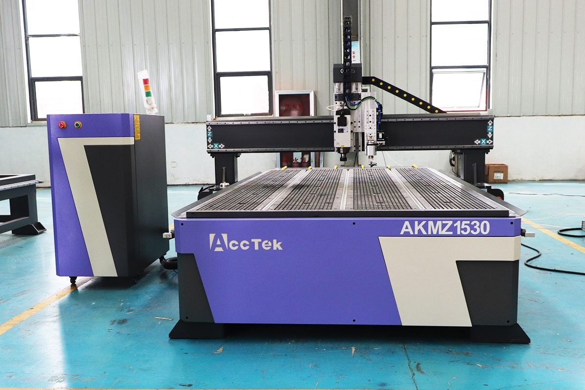
CNC Router Safety Operation Guide
CNC routers are widely used in woodworking, sign making, furniture manufacturing, plastics processing, composite fabrication, stone machining, prototyping, and many other industrial applications. By combining computer-controlled motion with high-speed cutting tools, these machines can perform cutting, engraving, drilling, grooving, shaping, and three-dimensional machining with excellent accuracy and repeatability. However, the same high-speed movement, rotating tools, electrical systems, dust generation, and automated operation that make CNC routers productive can also create serious safety hazards if the equipment is used incorrectly.
Safe CNC router operation depends on much more than simply knowing how to start the machine and load a program. Operators must understand machine structure, control functions, tooling requirements, material behavior, workholding methods, personal protective equipment, emergency procedures, and routine inspection practices. Improper tool installation, loose workpieces, incorrect machining parameters, damaged cutting tools, unexpected machine movement, or inadequate dust extraction can result in equipment damage, poor machining quality, fire hazards, flying debris, or personal injury.
Comprehensive CNC router safety programs should therefore cover every stage of operation, from pre-start inspection and machine setup to machining, maintenance, cleaning, and shutdown. Operators should receive proper training, follow manufacturer instructions, keep the working area organized, verify machining programs before execution, and never bypass guards, interlocks, or other protective systems.
This CNC router safety operation guide explains the essential precautions and operating practices required to use CNC routers safely and efficiently. It will examine common hazards, personal protective equipment, pre-operation checks, tool and workpiece preparation, safe machining procedures, emergency handling, maintenance precautions, and recommended workplace practices. By following standardized safety procedures, manufacturers can reduce accidents, protect equipment, improve machining reliability, and create a safer and more productive CNC working environment.
Table of Contents
Understand the Main Hazards of CNC Routers
CNC routers combine high-speed rotating tools, automated axis movement, electrical components, compressed air systems, vacuum equipment, and material-removal processes in a single machine. These features make CNC routers highly productive, but they also create multiple hazards that operators must understand before using the equipment. Some risks are obvious, such as contact with a rotating cutter, while others are less visible, including airborne dust, electrical faults, excessive noise, overheating, or unexpected movement caused by an incorrect program.
Safe operation begins with hazard awareness. Operators should know where danger zones are located, understand how different machine systems behave during operation, and recognize conditions that could lead to injury, fire, workpiece damage, or machine failure. Protective guards, emergency-stop systems, dust extraction equipment, proper workholding, personal protective equipment, and correct operating procedures all help reduce risk, but they are effective only when operators understand the hazards they are designed to control.
Rotating Spindle and Cutting Tool Hazards
The spindle and cutting tool are among the most obvious sources of danger on CNC routers. Depending on the application, the spindle may rotate at very high speeds, allowing cutting tools to remove material quickly and accurately. Direct contact with a rotating router bit can cause severe cuts, crushing injuries, or other serious harm. Operators should therefore never place their hands near the tool while the spindle is running or while residual rotation is still present after shutdown.
Cutting tools can also become dangerous if they are incorrectly installed, damaged, worn, or operated beyond their recommended conditions. A loose collet, improperly tightened tool, excessive tool overhang, or cracked cutter can cause the tool to break or be thrown from the spindle. Selecting the correct cutter for the material and machining operation is essential, as is verifying tool condition before each job.
Operators should wait until the spindle has completely stopped before removing chips, measuring a workpiece, changing tools, or performing adjustments. Machine guards and protective enclosures should remain in place whenever possible. Tool changes should only be performed according to the machine manufacturer’s procedure, with the spindle disabled and accidental startup prevented.
Moving Gantry and Axis Hazards
CNC routers use motor-driven axes to move the gantry, spindle, cutting head, or worktable according to programmed coordinates. These movements may occur quickly and sometimes unexpectedly, particularly during rapid positioning, homing, tool changes, or program execution. Operators standing inside the machine’s movement area can be struck, trapped, pinched, or crushed between moving and stationary components.
The gantry, Z-axis assembly, linear rails, rotary devices, tool changers, and other automated components should be treated as moving machinery whenever the control system is energized. Operators should avoid reaching into the machine during operation, even if the cutting tool appears far from the area being accessed. CNC programs can command rapid movement with little warning.
Before starting a machining cycle, operators should confirm that no tools, clamps, measuring instruments, loose materials, or body parts are within the machine’s travel path. Program simulations, dry runs, and reduced-speed testing can help identify unexpected movements before full production begins. Emergency-stop controls should remain accessible at all times.
Flying Chips and Workpiece Ejection
CNC routing produces chips, fragments, and debris that may be projected away from the cutting area at considerable speed. Sharp chips can strike the eyes or skin, while broken tool fragments can create an even greater hazard. Protective eyewear is therefore an important part of safe CNC router operation, even when the machine is equipped with a dust shoe or partial enclosure.
Workpiece ejection is another significant risk. If material is not properly secured, cutting forces may cause it to shift, rotate, lift, or be thrown from the worktable. Small parts are especially vulnerable when vacuum holding force decreases after much of the surrounding material has been removed.
Appropriate workholding methods should be selected according to workpiece size, geometry, material, and cutting strategy. These may include vacuum tables, clamps, fixtures, screws, or other suitable securing methods. Operators should verify that clamps do not interfere with the toolpath and that the workpiece remains firmly supported throughout the machining process.
Correct cutting parameters also matter. Excessive depth of cut, aggressive feed rates, incorrect spindle speed, or unsuitable tooling can generate abnormal cutting forces that increase the likelihood of tool breakage or material movement.
Dust and Airborne Particle Hazards
Routing wood, composites, plastics, stone, engineered boards, and other materials can generate significant quantities of dust and fine airborne particles. These contaminants may irritate the eyes, skin, and respiratory system, reduce workplace visibility, contaminate machine components, and create housekeeping problems.
Some materials produce particularly fine particles during cutting or engraving. Dust should therefore be controlled at the source whenever possible through an effective extraction system, dust shoe, enclosure, or centralized collection system. Filters, ducts, hoses, and collection containers should be inspected and maintained regularly so that airflow remains adequate.
Operators should avoid using compressed air to blow large quantities of fine dust into the surrounding workspace, as this can redistribute particles into the breathing zone. Appropriate respiratory protection may also be required depending on the material being processed, exposure conditions, local workplace requirements, and the effectiveness of the extraction system.
Dust accumulation can also contribute to equipment malfunction and fire risk. Regular cleaning of the machine, control cabinet surroundings, extraction system, and working area is therefore an important part of both occupational safety and equipment maintenance.
Noise and Vibration Hazards
CNC routers can generate high noise levels from the spindle, cutting tool, vacuum pump, dust collector, compressed air system, and cutting process itself. Noise levels vary considerably depending on the machine configuration, material, cutter type, spindle speed, feed rate, and surrounding environment.
Prolonged exposure to excessive noise can damage hearing. Workplaces should therefore assess actual noise exposure and use suitable hearing protection where required. Enclosures, acoustic barriers, properly maintained cutting tools, and optimized machining parameters may also help reduce noise.
Abnormal vibration is another warning sign that should not be ignored. Excessive vibration may result from an unbalanced or damaged tool, worn spindle bearing, loose collet, insufficient workpiece support, incorrect cutting parameters, or mechanical looseness. Continued operation under severe vibration can affect machining quality, shorten component life, and potentially contribute to tool failure.
Operators should stop the machine and investigate unusual vibration, rattling, or changes in operating sound rather than assuming that the condition is normal.
Electrical Hazards
CNC routers rely on electrical power for the spindle, servo or stepper motors, drives, control system, vacuum pumps, dust collectors, cooling systems, and auxiliary equipment. Damaged cables, loose connections, faulty grounding, moisture, overloaded circuits, or unauthorized electrical modifications can create risks of electric shock, equipment damage, or fire.
Control cabinets and electrical enclosures should normally remain closed during operation. Electrical inspection, repair, or modification should only be performed by appropriately qualified personnel. Before electrical maintenance begins, the machine should be isolated from its energy source using suitable shutdown and lockout procedures.
Operators should regularly check visible cables, plugs, connectors, and emergency controls for obvious damage. Coolant, water, cleaning fluids, and other liquids should be kept away from electrical equipment unless the system is specifically designed for such exposure.
Correct power supply specifications are also essential. Voltage, phase, frequency, grounding, and circuit protection should match the machine manufacturer’s requirements. Improper electrical installation can damage sensitive CNC components and create additional safety hazards.
Fire and Overheating Hazards
CNC routing can generate heat at the cutting zone, especially when tools become dull, feed rates are too low, chip evacuation is poor, or cutting parameters are unsuitable. Friction between a rotating cutter and combustible material can create smoldering, scorching, or, in severe cases, ignition.
Wood dust, plastic chips, extraction-system deposits, lubricants, and other combustible materials can increase fire risk when they accumulate near heat sources. Dust collectors require particular attention because large quantities of fine combustible particles may collect inside filters, hoses, and containers.
Operators should monitor the machining process for smoke, burning odors, unusual discoloration, excessive tool temperature, or abnormal spindle noise. CNC routers should not be left operating unattended where machine design, process risk, workplace procedures, or material characteristics require active supervision.
Fire extinguishing equipment appropriate for the workplace should be readily available, and operators should know how to respond to a fire emergency. Good housekeeping, sharp cutting tools, appropriate feeds and speeds, proper extraction, and routine machine inspection can significantly reduce overheating and ignition risks.
Pneumatic and Vacuum System Hazards
Many CNC routers use compressed air for tool changes, actuators, lubrication systems, dust removal, or other auxiliary functions. Vacuum pumps may also be used to secure workpieces to the table. Although these systems operate differently from the cutting spindle, they still store or generate energy that can create safety risks.
Compressed air lines, fittings, regulators, and hoses should be inspected for leakage, deterioration, or damage. A failed hose or loose fitting can move suddenly and may cause injury. Operators should not disconnect pressurized components until the system has been safely depressurized according to the manufacturer’s procedure.
Automatic tool changing systems deserve particular attention because pneumatic cylinders may move tool-change mechanisms unexpectedly if stored pressure remains in the system.
Vacuum workholding systems present different hazards. Insufficient vacuum can cause a workpiece to shift during cutting, particularly when machining small components, porous materials, or parts with limited contact area. Operators should verify vacuum pressure or holding performance before machining and ensure that seals, spoilboards, hoses, valves, and pumps are functioning correctly.
Vacuum pumps can also become hot during extended operation and may generate significant noise. Adequate ventilation, maintenance, and correct operating conditions help prevent overheating and premature equipment failure.
Understanding CNC router hazards is the foundation of safe machine operation. The main risks come from several interacting systems rather than from the cutting tool alone. High-speed spindles can cause severe injury, automated gantries can create crushing and pinch hazards, unsecured workpieces can be ejected, and chips or broken tools can become dangerous projectiles. At the same time, dust, noise, electrical equipment, heat, compressed air, and vacuum systems introduce additional hazards that may be less visible but are equally important to control.
Operators should approach CNC routers as complete automated machining systems. Before operation, the cutting tool, workpiece, workholding system, machine travel area, electrical condition, extraction equipment, and auxiliary systems should all be checked. During machining, operators should remain alert for unusual sound, vibration, smoke, excessive dust, workpiece movement, or unexpected machine behavior.
Protective equipment and safety devices should support, rather than replace, proper operating procedures. Guards, emergency stops, dust collection systems, eye and hearing protection, reliable workholding, and correct machine settings all contribute to reducing risk. Equally important are operator training, routine inspections, good housekeeping, proper maintenance, and compliance with the manufacturer’s safety instructions. By recognizing each major hazard and applying appropriate controls, CNC router users can reduce accidents, protect equipment, and maintain a safer and more reliable machining environment.
Understand CNC Router Safety Devices
CNC routers are equipped with various safety devices designed to reduce the risk of injury, equipment damage, unexpected machine movement, electrical faults, fire, and other operational hazards. These devices work together to help control dangerous conditions before they develop into serious incidents. However, safety systems can only provide effective protection when operators understand their purpose, inspect them regularly, and avoid bypassing or disabling them.
Different CNC router models may use different combinations of safety equipment depending on machine size, enclosure design, spindle power, control system, automation level, and intended application. Common devices include emergency stop buttons, machine guards, safety interlocks, limit switches, spindle protection systems, electrical protection components, dust collection systems, and visual or audible alarms. Some machines may also include automatic monitoring functions that stop operation when abnormal conditions are detected.
Operators should become familiar with the location and function of every safety device before starting the machine. Safety components should be included in routine pre-operation inspections, and any malfunction should be corrected before machining resumes. Safety devices should never be considered substitutes for proper training or correct operating procedures. Instead, they form an additional protective layer that helps reduce risk when combined with responsible machine operation.
Emergency Stop Buttons
Emergency stop buttons are among the most important safety devices on CNC routers. They are designed to stop machine operation quickly when an immediate hazard occurs, such as unexpected axis movement, workpiece displacement, tool breakage, abnormal vibration, smoke, or danger to an operator.
Emergency stop buttons are usually large, highly visible, and positioned where operators can reach them quickly. Larger CNC routers may have several emergency stops located around the machine, control panel, or operator station.
Before beginning work, operators should identify the position of every emergency stop and verify that access is not blocked by materials, tools, carts, or other equipment. Emergency stop functions should also be tested according to the manufacturer’s recommended inspection procedure.
Activating an emergency stop does not automatically make the machine safe for maintenance or manual intervention. The spindle or other components may continue moving briefly due to inertia, and electrical or pneumatic energy may remain present. After an emergency stop, operators should identify the cause of the problem and follow appropriate isolation procedures before approaching dangerous machine areas.
Emergency stop buttons should never be used routinely as a normal machine shutdown method unless specified by the manufacturer.
Machine Guards and Protective Covers
Machine guards and protective covers create physical barriers between operators and dangerous components. They may surround the cutting area, spindle, moving drive components, transmission systems, electrical equipment, tool changers, or other hazardous parts.
Guards can help prevent accidental contact with rotating tools and moving mechanisms while also containing chips, broken tool fragments, and cutting debris. Fully enclosed CNC routers provide particularly effective separation between operators and the machining area, while open-frame machines may rely on local guards, spindle covers, dust shoes, or perimeter barriers.
Protective covers also help keep contamination away from sensitive components such as linear guides, ball screws, racks, drive motors, and electrical systems. Maintaining these covers can improve both operator safety and machine reliability.
Operators should inspect guards for cracks, loose fasteners, damage, or improper positioning. Guards should not be removed during operation unless the machine is specifically designed to operate safely under those conditions.
If a guard must be removed for maintenance, cleaning, or adjustment, the machine should be properly isolated before work begins. Operating a machine with missing or damaged protective covers can expose personnel to unnecessary risks and should be avoided.
Safety Interlocks
Safety interlocks are control devices designed to prevent certain machine functions when safety conditions are not satisfied. They are commonly installed on doors, access panels, enclosures, tool changer areas, and other locations where operator access must be restricted during operation.
For example, an interlocked enclosure door may prevent spindle operation or pause machine movement if the door is opened. On more advanced CNC routers, interlocks may communicate directly with the control system to stop hazardous motion while maintaining safe system conditions.
Interlocks help reduce the likelihood that operators will enter dangerous areas while the spindle or axes are moving. They are especially important on enclosed high-speed machines and automated machining systems.
Operators should never defeat, bypass, tape down, mechanically block, or electrically disable an interlock to keep the machine running. Such actions remove an important layer of protection and can expose personnel to rotating tools, moving gantries, or automated mechanisms.
If the machine cannot operate because an interlock repeatedly triggers, the underlying cause should be investigated. A faulty sensor, misaligned door, damaged cable, or control problem should be repaired rather than bypassed.
Limit and Home Switches
Limit switches and home switches help the CNC control system monitor and control machine movement. Although these devices are primarily associated with positioning, they also provide important protection against excessive axis travel and mechanical collisions.
Home switches establish a known reference position when the machine performs a homing or referencing cycle. This allows the control system to determine the correct machine coordinate system before machining begins.
Limit switches are positioned near the allowable travel boundaries of machine axes. If an axis moves beyond its expected range, a limit switch can signal the control system to stop or restrict further movement.
These devices help reduce the risk of the gantry, spindle assembly, or worktable striking mechanical stops or moving beyond its designed travel. However, operators should not rely entirely on limit switches to prevent collisions. Incorrect work coordinates, tool offsets, fixtures, or CNC programs can still cause crashes within the normal travel area.
Limit and home switches should remain clean and properly aligned. Dust, chips, damaged cables, or loose mounting can interfere with their operation. If the machine repeatedly loses its home position or triggers abnormal limit alarms, the problem should be investigated before production continues.
Spindle Protection Systems
The spindle is one of the most heavily loaded and critical components of CNC routers. Spindle protection systems are designed to detect or prevent conditions that could lead to overheating, excessive current, lubrication problems, cooling failure, abnormal speed, or mechanical damage.
Depending on the machine configuration, protection may be integrated into the variable frequency drive, spindle drive, control system, or cooling unit. The system may generate an alarm or stop the spindle if operating parameters exceed safe limits.
Water-cooled spindles may include cooling-flow monitoring, temperature protection, or chiller alarms. Air-cooled spindles depend on sufficient airflow and should not be operated if cooling passages, fans, or ventilation openings are blocked.
Overcurrent and overload protection can help prevent damage when the spindle is subjected to excessive cutting forces. Abnormal loads may result from unsuitable tools, incorrect feed rates, excessive cutting depth, tool wear, or mechanical binding.
Operators should respond immediately to spindle alarms rather than repeatedly resetting them without identifying the cause. Continuing to operate an overheating, overloaded, or poorly cooled spindle can result in premature bearing failure, electrical damage, tool failure, or unexpected shutdown.
Dust Collection Systems
Dust collection systems are an important part of CNC router safety, particularly when machining materials that generate large quantities of fine particles. A properly designed extraction system helps capture dust close to the cutting zone before it spreads throughout the workplace.
Typical systems include spindle-mounted dust shoes, extraction hoses, ducting, filters, separators, collection bags or bins, and industrial dust collectors. These components help improve air quality, visibility, housekeeping, and machine cleanliness.
Dust extraction also reduces the accumulation of combustible particles around the spindle, electrical equipment, worktable, and machine frame. Excessive dust buildup can contribute to overheating, interfere with sensors, increase maintenance requirements, and raise fire risk.
Operators should inspect dust hoses for blockage, damage, leakage, or disconnected fittings. Filters and collection containers should be maintained according to the manufacturer’s recommendations. A full collection bin or clogged filter can significantly reduce airflow even when the dust collector still appears to be running.
Dust collection systems should be matched to the type and volume of dust generated. Appropriate equipment and procedures are especially important when processing materials that produce hazardous, combustible, or very fine particulate matter.
Electrical Protection Devices
Electrical protection devices help protect operators and machine components from short circuits, overloads, ground faults, excessive current, voltage irregularities, and other electrical problems.
Common electrical safety components include circuit breakers, fuses, overload relays, grounding systems, protective contactors, surge protection devices, and residual-current or ground-fault protection where appropriate. Variable frequency drives, servo drives, and control systems may also include integrated fault detection.
When an electrical protective device trips, it usually indicates that an abnormal condition has occurred. Operators should avoid repeatedly resetting breakers or replacing fuses without determining why the protection activated.
Loose electrical connections, damaged cables, motor overload, moisture, dust contamination, component failure, or incorrect power supply conditions can all cause electrical faults.
Control cabinets should remain closed during normal operation to help prevent accidental contact with energized components and reduce contamination. Electrical work should only be performed by properly qualified personnel.
Reliable grounding is particularly important for CNC equipment because it contributes to both electrical safety and stable operation of electronic control systems. Any damaged electrical protection device should be repaired or replaced before the machine returns to service.
Warning Lights, Alarms, and Safety Labels
Warning lights, audible alarms, and safety labels communicate machine status and alert operators to potential hazards. They provide important information before and during CNC router operation.
Indicator lights may show whether the machine is powered, operating, paused, waiting for intervention, or experiencing a fault. Multi-color stack lights are common on automated CNC equipment and allow machine status to be recognized from a distance.
Audible alarms may activate before machine movement, during automatic tool changing, when a fault occurs, or when operator attention is required. These warnings should never be ignored simply because they occur frequently.
Safety labels identify hazards such as high voltage, rotating tools, pinch points, hot surfaces, moving machinery, compressed air, or required personal protective equipment. Labels should remain visible, clean, and legible.
If a warning label becomes damaged or unreadable, it should be replaced with an appropriate label. Operators should understand the meaning of all machine warnings before using the CNC router.
Alarms should also be treated as diagnostic information. Repeated spindle, servo, vacuum, cooling, or electrical alarms can indicate developing equipment problems. Investigating them promptly can prevent larger failures and reduce safety risks.
CNC router safety devices provide multiple layers of protection against mechanical, electrical, environmental, and operational hazards. Emergency stop buttons allow operators to respond quickly to dangerous situations, while guards and protective covers help separate personnel from rotating tools, moving axes, and flying debris. Safety interlocks reduce the possibility of operating the machine with access points open, and limit and home switches help control axis travel and maintain accurate machine positioning.
Spindle protection systems monitor critical operating conditions such as overload, temperature, and cooling performance. Dust collection systems reduce airborne contamination, maintain a cleaner working environment, and help control dust-related fire hazards. Electrical protection devices respond to abnormal current, faults, and other power-related problems, while warning lights, alarms, and safety labels keep operators informed about machine status and potential danger.
These safety devices should never be bypassed simply to increase production speed or avoid troubleshooting. A machine that cannot operate normally with its safety systems functioning should be inspected and repaired before production continues.
Operators should know the location, purpose, and correct use of every safety device on their CNC router. Regular inspection, functional testing, cleaning, maintenance, and prompt repair of defective components are essential. When reliable safety devices are combined with proper training, disciplined operating procedures, appropriate personal protective equipment, and good workplace practices, they significantly reduce the likelihood of accidents and support safer, more dependable CNC router operation.
Wear Proper Personal Protective Equipment
Personal protective equipment is an essential part of CNC router safety because it helps protect operators from hazards that cannot always be eliminated through machine design, guards, dust collection, or safe operating procedures alone. CNC routing can generate flying chips, broken tool fragments, fine dust, high noise levels, sharp workpiece edges, and other hazards that may expose the eyes, hearing, respiratory system, feet, and body to injury.
The specific personal protective equipment required depends on the machine configuration, processed material, cutting operation, workplace environment, and effectiveness of existing engineering controls. At a minimum, operators should evaluate eye protection, hearing protection, respiratory protection, safety footwear, and appropriate work clothing before beginning machining. Additional protection may be necessary for certain materials or tasks.
Personal protective equipment should fit correctly, remain in good condition, and be suitable for the specific hazard. Damaged safety glasses, poorly fitted respirators, worn footwear, or inappropriate clothing can reduce protection and create additional risks. Operators should also understand that some items that appear protective can actually become dangerous around rotating machinery. Gloves, loose sleeves, jewelry, and unsecured long hair, for example, can become caught in moving equipment.
PPE should therefore be considered one part of broader CNC router safety systems. It should complement machine guards, dust extraction, safe workholding, proper training, and established operating procedures rather than replace them.
Safety Glasses and Face Protection
Eye protection is one of the most important requirements when operating CNC routers. Cutting and engraving processes can eject chips, splinters, dust, broken cutter fragments, and small pieces of workpiece material at high speed. Even machines equipped with dust shoes or partial enclosures may not completely contain every particle.
Operators should wear appropriate safety glasses with suitable impact protection whenever they are exposed to the machining area. Protective eyewear should fit securely and provide adequate coverage around the eyes. Regular prescription glasses generally should not be considered a substitute unless they are specifically designed and rated as safety eyewear.
Additional face protection may be appropriate during operations that produce large quantities of chips, brittle fragments, or other high-impact debris. A face shield can provide additional protection for the face, but it should generally be used together with suitable safety glasses rather than as the only form of eye protection.
Eye protection is also important during setup and cleaning. Removing chips from fixtures, changing cutting tools, cleaning dust collection components, or handling brittle workpieces can expose operators to particles even when the machine is not actively cutting.
Safety glasses and face shields should be kept clean and inspected regularly. Scratched lenses, cracked shields, damaged frames, or loose fittings can reduce visibility and protection and should be replaced when necessary.
Hearing Protection
CNC routers can generate significant levels of noise from several sources at the same time. The spindle, cutting process, vacuum pump, dust collector, compressed air equipment, drive system, and material vibration can all contribute to the overall sound level.
Repeated or prolonged exposure to excessive noise can gradually damage hearing, sometimes without immediate symptoms. Operators working near CNC routers should therefore assess the noise level in the machining environment and use hearing protection where required.
Common options include earplugs and earmuffs. The appropriate type depends on the actual sound level, duration of exposure, comfort, workplace requirements, and the need to hear alarms or communication. Hearing protection should fit correctly to provide its intended level of attenuation.
Operators should not simply compensate for high machine noise by using stronger hearing protection without investigating whether the noise is abnormal. Sudden increases in sound level, rattling, grinding, squealing, or unusual spindle noise may indicate worn bearings, loose components, damaged cutting tools, incorrect cutting parameters, or mechanical problems.
Reducing noise at its source is always desirable. Sharp tools, correct feeds and speeds, suitable workholding, machine enclosures, acoustic barriers, and regular maintenance can help reduce unnecessary noise while improving machining quality.
Respiratory Protection
CNC routing can generate dust and airborne particles that may be harmful when inhaled. The quantity and nature of the dust depend on the material being machined, tool geometry, cutting parameters, extraction efficiency, and duration of exposure.
Wood, engineered boards, composites, plastics, stone, and other materials can produce fine particles that remain suspended in the air after machining. Some dust may irritate the nose, throat, and lungs, while certain materials may require stricter exposure controls because of their chemical composition or particle characteristics.
The primary method of controlling dust should be effective extraction at the source. Dust shoes, local extraction systems, enclosed machining areas, and properly maintained dust collectors can significantly reduce airborne contamination. Respiratory protection should be used when these engineering controls cannot adequately reduce exposure or when workplace safety requirements specify its use.
The respirator or mask selected should be appropriate for the type of contaminant and the level of exposure. Proper fit is important because gaps around the face can significantly reduce protection. Disposable masks, reusable respirators, and specialized filtration systems provide different levels of protection and should be selected according to actual operating conditions.
Respiratory protective equipment should be kept clean, stored properly, and replaced or maintained according to the manufacturer’s instructions. Filters should not be used beyond their recommended service life.
Safety Footwear
Safety footwear helps protect operators from injuries caused by falling tools, heavy workpieces, sharp debris, and accidental contact with equipment or material-handling devices. CNC router environments often involve large sheets, fixtures, clamps, tooling, and machine components that can cause serious foot injuries if dropped.
Appropriate safety shoes should provide stable footing and protection suitable for the workplace. Toe protection may be particularly important when handling heavy panels, stone workpieces, fixtures, motors, or other substantial components.
Slip resistance is another important consideration. Dust, chips, lubricants, coolant, and other debris can accumulate around CNC routers and create slippery surfaces. Proper footwear can help reduce the likelihood of slips and falls, although good housekeeping remains the primary control.
Operators should avoid sandals, open-toed shoes, or other footwear that provides inadequate protection in an industrial machining environment. Loose or damaged footwear can also interfere with safe movement around the machine.
Safety shoes should fit comfortably enough to support long periods of standing and movement. Worn soles, damaged toe protection, or loose footwear should be replaced before they create additional risks.
Appropriate Work Clothing
Operators should wear clothing that protects the body without creating an entanglement hazard. Proper work clothing should fit relatively close to the body, allow comfortable movement, and avoid loose fabric that could contact rotating tools or moving machine parts.
Long sleeves may provide some protection against chips and minor abrasions, but sleeves should be properly fitted and secured at the wrists. Loose cuffs, oversized jackets, scarves, ties, and hanging drawstrings should not be worn near CNC equipment.
Work clothing should also be selected with the processed material and working environment in mind. Clothing that becomes heavily contaminated with dust, oil, or combustible residue should be cleaned or replaced rather than worn repeatedly around ignition sources.
Operators performing setup, loading, unloading, or cleaning should also consider the possibility of contact with sharp workpiece edges. Appropriate clothing can help reduce minor cuts and abrasions, although it should never be relied upon as the primary protection against sharp tools.
High-visibility clothing may be useful in larger manufacturing environments where forklifts, material handling systems, or multiple machines operate in the same area. However, any reflective strips, vests, or outer garments should still fit securely and should not contain loose sections that could become caught in machinery.
Hair, Jewelry, and Loose Clothing Precautions
Long hair, jewelry, and loose clothing can create serious entanglement hazards around CNC routers. The rotating spindle, cutting tool, couplings, drive components, tool changers, and other moving mechanisms can catch hanging objects rapidly and pull them into the machine.
Operators with long hair should tie it back securely and keep it away from moving machinery. Hair should not hang forward when leaning over a worktable or machine enclosure during setup or inspection.
Jewelry such as necklaces, bracelets, dangling earrings, rings, watches, and chains should be evaluated carefully before machine operation. Hanging jewelry should be removed because it can become caught in moving parts. Rings and watches may also present hazards when handling machinery, tools, fixtures, or electrical equipment.
Loose clothing should be secured before approaching the CNC router. Open jackets, oversized sleeves, ties, scarves, hood strings, loose belts, and other hanging items should not be worn near rotating or moving machine components.
These precautions apply not only while the machine is actively cutting but also during setup, manual jogging, tool changing, inspection, and maintenance. Unexpected machine movement can occur whenever the equipment is energized, so operators should maintain appropriate clothing and personal appearance practices throughout the entire work process.
When Gloves Should and Should Not Be Worn
Gloves require special consideration in CNC router operations because they can either provide useful protection or create a serious entanglement hazard depending on the task.
Gloves may be appropriate when handling rough, sharp, splintered, or abrasive workpieces while the CNC router is stopped and properly secured. They can help protect the hands when loading raw materials, unloading finished parts, cleaning sharp chips manually with appropriate tools, handling sheet edges, or performing certain maintenance activities.
Cut-resistant gloves may be useful when handling components with sharp edges, while chemical-resistant gloves may be necessary when working with specific cleaning agents or maintenance fluids. The glove type should always match the actual hazard.
However, gloves generally should not be worn when the hands may come close to a rotating spindle, cutting tool, exposed rotating shaft, or other moving component. A glove can become caught more easily than bare skin and may pull the operator’s hand or arm into the machinery.
Operators should never use gloved hands to touch, steady, clean, or adjust a workpiece while the spindle is rotating. Chips should not be removed by hand while the machine is running, whether gloves are worn or not.
Gloves should also be removed before performing tasks where they could become caught in automated mechanisms. Before deciding to wear gloves, operators should consider whether the machine is completely stopped, isolated where necessary, and free from rotating or moving hazards.
Proper personal protective equipment helps reduce the likelihood and severity of injuries during CNC router operation, but PPE must be carefully selected and used correctly. Safety glasses protect against flying chips, dust, and broken tool fragments, while face shields can provide additional protection for operations that generate greater levels of debris. Hearing protection helps reduce exposure to prolonged machine noise, and respiratory protection may be necessary when dust extraction alone cannot adequately control airborne particles.
Safety footwear protects against falling objects, sharp debris, and slippery working surfaces, while properly fitted work clothing helps protect the body without creating unnecessary entanglement risks. Long hair should be secured, jewelry should be removed where appropriate, and loose clothing should never be allowed near rotating or moving machine components.
Glove use requires particular caution. Gloves can protect the hands when handling sharp or rough materials while the machine is safely stopped, but they can become extremely dangerous around rotating spindles, cutters, and other moving components. Operators must understand when gloves provide protection and when they introduce additional risk.
PPE should always be used together with machine guards, dust collection systems, safe workholding, correct machining procedures, proper training, and regular equipment maintenance. Operators should inspect protective equipment before use, replace damaged items, and follow both manufacturer instructions and applicable workplace safety requirements. A disciplined approach to personal protection helps create safer CNC router environments while supporting efficient and reliable daily operation.
Prepare Safe CNC Router Work Areas
Safe CNC router work areas are an essential foundation for reliable machine operation. Even when CNC routers are equipped with guards, emergency stops, dust extraction, and other protective devices, poor workplace conditions can introduce additional hazards. Cluttered floors, inadequate lighting, restricted access, loose electrical cables, poor ventilation, and accumulated combustible dust can increase the likelihood of slips, collisions, fires, electrical problems, and delayed emergency response.
Work area preparation should therefore be treated as part of the normal CNC router operating procedure rather than as a separate housekeeping task. The area surrounding the machine should provide enough space for operators to load and unload workpieces, perform inspections, access controls, and respond safely if a problem develops. Electrical cables, pneumatic hoses, vacuum lines, dust collection ducts, and auxiliary equipment should be arranged so that they do not obstruct walkways or interfere with moving machine components.
Environmental conditions also influence both operator safety and machine reliability. Adequate lighting makes it easier to identify damaged tools, loose fixtures, and machining problems, while proper ventilation and dust extraction help control airborne contaminants. Combustible materials should be separated from potential heat sources, and emergency equipment must always remain accessible.
By organizing the CNC router work area carefully and maintaining it consistently, operators can reduce unnecessary hazards and create better conditions for safe, efficient, and predictable machining.
Keep the Machine Area Clean and Organized
Good housekeeping is one of the simplest and most effective ways to improve CNC router safety. Routing operations can produce chips, dust, offcuts, packaging materials, broken tools, and other debris that quickly accumulates around the machine if it is not regularly removed.
Chips and dust on the floor can create slipping hazards, while larger offcuts may cause operators to trip or obstruct access to machine controls. Tools, measuring instruments, clamps, and maintenance equipment left in inappropriate locations may also fall into the machining area or interfere with moving components.
Operators should establish designated storage areas for cutting tools, collets, fixtures, measuring equipment, cleaning supplies, and commonly used accessories. Tools should be returned to their proper locations after use rather than being left on the CNC router table, control cabinet, machine frame, or nearby floor.
The worktable itself should also remain clean. Chips, dust, and debris underneath a workpiece can affect positioning, reduce vacuum holding force, and prevent the material from lying flat. Before loading a new workpiece, the table and workholding surfaces should be inspected and cleaned as necessary.
Dust collection containers and waste bins should be emptied regularly before they overflow. Routine cleaning not only improves safety but also makes abnormal conditions such as leaks, loose fasteners, damaged cables, or mechanical wear easier to detect.
Maintain Adequate Working Clearance
Adequate clearance around CNC routers allows operators to work safely during loading, unloading, setup, inspection, cleaning, and maintenance. Crowding equipment too closely together can restrict movement and increase the risk of contact with the machine, materials, or other workers.
The amount of clearance required depends on machine dimensions, workpiece size, door or enclosure movement, gantry configuration, control-panel location, and material handling methods. Large-format CNC routers may require substantial free space around the loading and unloading sides because full-size sheets or long workpieces must be moved into position.
Operators should have unobstructed access to the control panel, emergency stop buttons, electrical disconnects, dust collection components, and other important equipment. Service areas around electrical cabinets, motors, vacuum pumps, and lubrication systems should also remain accessible for inspection and maintenance.
The machine’s complete movement envelope must be considered. Moving gantries, rotary attachments, automatic tool changers, or other automated components may extend beyond positions that appear safe while the machine is idle.
Material carts, toolboxes, waste containers, and temporary workpieces should not be placed inside required operating clearances. Clearly marked walkways or restricted zones can help personnel recognize areas that must remain unobstructed.
Sufficient working space helps operators maintain stable body positioning, handle materials properly, and move away from the machine quickly if an unexpected situation occurs.
Provide Sufficient Lighting
Good lighting is necessary for safe setup, operation, inspection, and maintenance of CNC routers. Poor visibility can make it difficult to identify damaged cutting tools, incorrectly positioned clamps, surface defects, loose connections, or debris that may interfere with machining.
The general work area should have sufficient and evenly distributed illumination without excessive shadows. Additional task lighting may be useful around the spindle, tool changer, worktable, maintenance areas, or electrical cabinet when detailed inspection is required.
Lighting should be positioned so that it does not create distracting glare on machine displays, transparent guards, polished surfaces, or workpieces. Operators must be able to read control screens, warning labels, tool markings, scales, and machine indicators easily.
Adequate lighting is particularly important during tool setup. Small cracks, chipped cutting edges, incorrectly seated tools, or contamination inside collets can sometimes be difficult to identify under poor lighting conditions.
Lighting fixtures should also be appropriate for the industrial environment. Dust and vibration can affect ordinary fixtures over time, so lights around machining areas should be inspected and maintained regularly.
Portable lighting may sometimes be needed for maintenance, but cords and lamps should be positioned so they do not create tripping hazards or contact moving machine components. Where electrical maintenance is involved, suitable lighting equipment and electrical safety procedures should be used.
Maintain Proper Ventilation
Ventilation helps control airborne dust, fumes, heat, and other contaminants generated during CNC router operation. Although local dust extraction should capture contaminants as close to the cutting zone as possible, general workplace ventilation provides an additional layer of air-quality control.
Different materials can produce different airborne contaminants. Routing wood and engineered boards can create fine dust, while machining certain plastics, composites, coatings, or adhesives may produce particles, odors, or fumes. Appropriate ventilation should therefore be based on the materials and processes used in the facility.
Airflow should remove contaminated air effectively without disrupting dust collection performance or blowing chips and dust into other occupied areas. Simply using fans to redistribute contaminated air around a workshop is not an effective substitute for proper extraction and ventilation.
Ventilation is also important for heat-generating auxiliary equipment. Vacuum pumps, spindle chillers, electrical control cabinets, dust collectors, and air compressors may release significant heat during extended production. Sufficient airflow around this equipment helps maintain proper operating temperatures and can reduce the likelihood of overheating.
Ventilation openings, filters, fans, and ducts should be kept clean and unobstructed. If operators notice persistent dust clouds, unusual odors, excessive heat, or poor air quality, machining conditions and ventilation performance should be investigated before continuing prolonged operation.
Keep Combustible Materials Away
CNC routing can generate heat, friction, sparks under certain abnormal conditions, and large quantities of combustible dust or chips. Keeping unnecessary combustible materials away from the machine helps reduce the chance that a small overheating event develops into a larger fire.
Cardboard boxes, paper, oily rags, packaging materials, solvents, waste, and other combustible items should not be stored around the spindle, electrical cabinets, motors, dust collectors, or other potential heat sources.
Particular attention should be given to accumulated dust. Fine combustible dust can build up inside extraction hoses, filters, machine enclosures, electrical areas, and surrounding surfaces. Regular cleaning and proper dust collection maintenance are therefore essential parts of fire prevention.
Cutting tools should remain sharp, and appropriate machining parameters should be used. A dull cutter, excessive friction, inadequate chip evacuation, or incorrect feed rate can increase cutting temperature and potentially scorch combustible workpieces.
Operators should remain alert for smoke, burning odors, discolored material, unusual tool heat, or visible smoldering. These warning signs should never be ignored.
Where flammable liquids or chemicals are needed for maintenance or cleaning, they should be stored and handled according to appropriate workplace requirements and kept away from ignition sources. Suitable fire extinguishing equipment should also be available according to the hazards present in the facility.
Secure Electrical and Pneumatic Connections
Electrical cables, compressed air lines, vacuum hoses, cooling pipes, and communication cables are commonly connected to CNC routers and their auxiliary equipment. Poorly routed or damaged connections can create electrical, mechanical, and tripping hazards.
Power cables should be protected from sharp edges, crushing, excessive bending, heat, water, and moving machine components. Extension cords or temporary electrical connections should not be used as permanent substitutes for correctly installed power supplies.
Electrical plugs, connectors, grounding conductors, and visible cables should be inspected regularly. Damaged insulation, exposed conductors, loose connections, or signs of overheating should be addressed before the machine is operated.
Pneumatic hoses should also be properly routed and secured. Loose compressed-air hoses can become damaged by carts, workpieces, or machine movement. A hose that disconnects while pressurized may move violently and cause injury.
Air fittings, regulators, filters, and pressure gauges should be inspected for leakage or damage. Pneumatic systems should operate within the pressure limits specified by the equipment manufacturer.
Vacuum and dust extraction hoses should be arranged so that they cannot become caught by the moving gantry or spindle assembly. Cable carriers and suitable supports can help guide moving cables and hoses safely throughout machine travel.
Keeping connections organized protects equipment while reducing obstacles and making routine inspections easier.
Keep Emergency Exits and Equipment Accessible
Emergency exits and safety equipment must remain immediately accessible whenever CNC routers are operating. Materials, carts, waste containers, tools, or temporary storage should never obstruct emergency routes.
Operators should know the location of emergency exits and understand the safest route out of the work area. Walkways leading to these exits should remain clearly marked and free of dust, chips, cables, hoses, or other objects that could delay evacuation.
Machine emergency stop buttons must also remain unobstructed. Operators should be able to reach them quickly without having to move materials or enter a hazardous machine area.
Other emergency equipment may include fire extinguishers, first-aid supplies, electrical disconnects, alarm controls, eye-washing facilities, or other workplace-specific safety equipment. Access to these devices should never be compromised for convenience or temporary storage.
Fire extinguishers should be positioned according to applicable workplace requirements and selected for the types of fire hazards present. Operators expected to use emergency equipment should understand the facility’s emergency procedures and receive appropriate training.
Emergency access should be considered whenever the production layout changes. Installing new machines, adding material racks, or temporarily storing large workpieces can unintentionally restrict previously clear routes. Periodic workplace inspections can help ensure that emergency equipment and evacuation paths remain ready for use.
Preparing safe CNC router work areas requires attention to much more than the machine itself. Workplace organization, sufficient clearance, adequate lighting, proper ventilation, fire prevention, secure utility connections, and clear emergency access all contribute to safer daily operation.
The area around the CNC router should remain clean and free from unnecessary tools, chips, dust, offcuts, and other obstacles. Adequate clearance should allow operators to load workpieces, reach machine controls, perform maintenance, and move safely without entering hazardous machine zones. Good lighting makes setup errors and damaged components easier to identify, while effective ventilation and dust extraction reduce exposure to airborne contaminants and excess heat.
Combustible materials and accumulated dust should be controlled to reduce fire risk. Electrical cables, pneumatic lines, vacuum hoses, and other connections should be correctly routed, protected, and regularly inspected. At the same time, emergency exits, stop controls, fire extinguishers, electrical disconnects, and other safety equipment must remain visible and immediately accessible.
A safe work area requires continuous attention rather than one-time preparation. Production activities can quickly introduce new materials, waste, cables, or equipment into previously clear areas. Regular housekeeping and workplace inspections should therefore form part of the daily CNC router safety routine. By maintaining a clean, organized, well-lit, and properly ventilated workspace with clear emergency access, operators can reduce preventable hazards and support safer, more efficient, and more reliable CNC machining.
Perform Pre-Operation Safety Inspections
Pre-operation safety inspections are one of the most important steps before starting CNC routers. Even when a machine operated normally during the previous shift, loose fasteners, worn tools, damaged cables, clogged dust extraction components, lubrication problems, or other faults may develop between production cycles. Identifying these issues before machining begins helps reduce the risk of injury, machine damage, poor cutting quality, unexpected shutdowns, and costly production interruptions.
The inspection should follow a consistent routine and cover both the CNC router itself and its supporting systems. Operators should examine the machine structure, guards, emergency stops, spindle, tool holder, cutting tools, worktable, workholding equipment, dust collection system, lubrication and cooling systems, and visible electrical connections. The purpose is not only to find obvious damage, but also to identify abnormal conditions that could become dangerous during high-speed operation.
Operators should never assume that a machine is safe simply because it powers on without an alarm. Some mechanical or workholding problems may not be detected by the control system. If damage, unusual wear, leaks, loose parts, or defective safety devices are discovered, the machine should not be used until the issue has been properly evaluated and corrected.
A systematic pre-operation inspection requires only a small amount of time compared with the consequences of tool failure, workpiece ejection, spindle damage, fire, or unexpected machine movement.
Check the Machine for Visible Damage
The inspection should begin with a general visual examination of the entire CNC router. Operators should look for obvious damage, loose components, missing fasteners, cracks, bent parts, unusual wear, fluid leaks, or signs that the machine has been struck or overloaded.
The machine frame, gantry, spindle assembly, linear guides, rack-and-pinion systems, ball screws, cable carriers, and other visible mechanical components should be checked for abnormal conditions. Covers or structural components that appear loose or displaced should be investigated before operation.
Operators should also look for accumulated chips or foreign objects inside moving areas. Tools, offcuts, clamps, measuring devices, or maintenance items left on the machine can interfere with gantry movement and cause collisions.
Any unusual condition should be compared with the machine’s normal appearance and operating state. If the machine was recently repaired, transported, or subjected to a crash, a more detailed inspection may be necessary before production resumes.
Visible damage should never be ignored simply because the machine can still move. A small crack, loose bracket, damaged cable carrier, or bent component can become a more serious failure under cutting loads and high-speed motion.
Inspect Guards and Protective Covers
Machine guards and protective covers help prevent accidental contact with moving components and contain chips, dust, and broken tool fragments. Before operation, operators should confirm that all guards are correctly installed, securely fastened, and free from significant damage.
Transparent enclosure panels should be checked for cracks or severe damage that could reduce their ability to contain debris. Hinges, latches, access doors, and protective panels should open and close correctly.
Covers protecting linear guides, ball screws, drive systems, belts, gears, and electrical components should also be inspected. Loose or damaged covers may interfere with machine motion or allow contamination to enter sensitive components.
If the CNC router uses safety interlocks on enclosure doors or access panels, operators should make sure the doors close correctly and that interlock components are not damaged, blocked, or intentionally bypassed.
Dust shoes and local spindle guards should also be examined because they may become cracked or displaced during previous machining operations.
Any guard removed for maintenance should be reinstalled before the machine returns to normal operation. Operating without required protective covers exposes both personnel and machine components to unnecessary risk.
Test Emergency Stop Functions
Emergency stop controls must be functional before machining begins. Operators should know the location of every emergency stop button installed on the CNC router and confirm that each one is easy to reach.
Testing procedures should follow the manufacturer’s instructions because CNC systems differ in how emergency stops affect spindle rotation, servo power, axis movement, pneumatic equipment, and auxiliary devices.
A functional emergency stop should interrupt hazardous operation as designed and place the machine into a safe control state. After testing, the operator should confirm that the machine cannot restart unexpectedly and that the reset procedure functions correctly.
Emergency stop buttons should move freely and should not be obstructed by tools, material, packaging, or other objects. Damaged, loose, or difficult-to-operate controls should be repaired before production begins.
Operators should also understand that an emergency stop is not a replacement for complete energy isolation during maintenance. Residual electrical, pneumatic, or mechanical energy may remain after the button is activated.
Regular testing is especially important after electrical maintenance, control-system changes, machine relocation, or repairs involving safety circuits.
Inspect the Spindle and Tool Holder
The spindle and tool holder directly affect cutting performance and operator safety, so they require careful inspection before every machining job.
Operators should first check the spindle body for visible damage, unusual looseness, contamination, or signs of overheating. Cooling openings or fans on air-cooled spindles should remain clean and unobstructed. Water-cooled systems should show no visible leakage around the spindle or cooling connections.
The collet, chuck, tool holder, and retaining components should be clean and properly assembled. Dust, resin, chips, or other debris inside a collet or taper can prevent correct tool seating and increase runout.
Tool holders should be inspected for cracks, excessive wear, damaged threads, deformation, or contaminated mating surfaces. Automatic tool-changing systems require additional attention because worn or damaged holders can affect tool retention during high-speed spindle operation.
The cutting tool should be inserted to an appropriate depth and tightened according to the spindle or tooling manufacturer’s requirements. Excessive tool extension can increase vibration and bending forces.
If abnormal spindle play, noise, bearing roughness, or holder damage is found, machining should not continue until the cause has been investigated.
Check Cutting Tools for Damage or Wear
Cutting tools operate at high rotational speeds and are subjected to continuous mechanical and thermal stress. A damaged or worn cutter can break unexpectedly, produce excessive vibration, overheat the workpiece, or create poor machining results.
Before installation, operators should inspect the cutting edges, shank, flutes, and overall tool condition. Chipped edges, cracks, bends, severe wear, corrosion, or damage from previous collisions are signs that the tool should not be used.
Tool sharpness is also important. Dull cutters require greater cutting force and can increase spindle load, vibration, friction, and heat generation. These conditions may contribute to workpiece movement, scorching, poor surface finish, or tool failure.
Operators should verify that the selected tool is suitable for the material, spindle speed, feed rate, depth of cut, and machining operation. The tool diameter and length should also match the CNC program and tool-offset settings.
If an automatic tool changer is used, every tool expected to be used in the program should be checked rather than only the first tool.
Cutting tools should be replaced based on condition and actual service requirements rather than waiting for complete failure.
Inspect the Worktable
The worktable provides the foundation for workpiece positioning and secure holding, so its condition directly affects both safety and machining accuracy.
Before loading material, operators should remove chips, dust, scraps, broken tools, and other debris from the table surface. Foreign material underneath a workpiece can prevent it from lying flat and may reduce workholding effectiveness.
T-slot tables should be inspected for damaged slots, loose fasteners, embedded debris, or damaged clamping hardware. Vacuum tables require clean sealing surfaces and should be checked for damaged zones, blocked ports, or excessive leakage.
Spoilboards should be examined for deep cuts, uneven surfaces, severe wear, or damage that could reduce vacuum holding performance. A heavily worn spoilboard may allow air leakage and make smaller workpieces difficult to secure.
Operators should also check that nothing protrudes unexpectedly above the table surface where it could collide with the cutting tool.
If the table has recently been resurfaced, repaired, or modified, the machine work coordinate and tool clearances should be verified before production begins.
Check the Workholding System
Reliable workholding is essential because an unsecured workpiece can shift, rotate, lift, or be ejected during cutting. The workholding method should therefore be inspected carefully before each machining cycle.
When mechanical clamps are used, operators should confirm that all clamps are secure and positioned outside the programmed toolpath. Loose clamps can allow material movement, while incorrectly placed clamps can cause a severe tool collision.
For vacuum workholding, operators should verify that the vacuum pump is functioning correctly and that sufficient holding force can be achieved. Hoses, valves, seals, gaskets, and vacuum zones should be checked for leaks or damage.
The workpiece itself should make adequate contact with the table or fixture. Warped sheets, small components, porous materials, or parts with limited surface area may require additional workholding methods.
Fixtures, stops, screws, and locating devices should be securely fastened and appropriate for the cutting forces generated by the process.
Operators should also consider whether the machining program will reduce holding force as material is removed. Small finished parts may become loose near the end of a cut and may require tabs, bridges, additional vacuum zones, or other retention strategies.
Inspect the Dust Collection System
The dust collection system should be inspected before machining because poor extraction can reduce visibility, increase airborne particle exposure, contaminate machine components, and contribute to fire risk.
Operators should confirm that the dust collector is connected properly and ready for operation. Hoses and ducts should be checked for cracks, loose fittings, blockages, or sections that could interfere with gantry travel.
The spindle-mounted dust shoe should be inspected for damage, correct positioning, and excessive wear. Brushes or skirts should remain capable of surrounding the cutting zone without interfering with the tool or workpiece.
Collection bags, bins, separators, and filters should be checked to make sure they are not full. A clogged filter or overloaded container can greatly reduce airflow even though the extraction system continues running.
Dust hoses should remain securely supported and should not hang inside moving machine areas.
Operators should also check for heavy dust accumulation around electrical cabinets, motors, spindle components, or other heat-producing equipment. Excessive buildup should be cleaned before machining begins.
If extraction performance appears weaker than normal, the cause should be corrected rather than simply operating the machine with reduced airflow.
Check Lubrication and Cooling Systems
Proper lubrication and cooling help prevent excessive wear, overheating, and mechanical failure during CNC router operation. These systems should therefore be included in the pre-operation inspection.
If the machine has an automatic lubrication system, operators should check the lubricant level and look for warning indicators, damaged lines, leaks, or blocked fittings. Manual lubrication points should be serviced according to the manufacturer’s maintenance schedule.
Linear guides, ball screws, bearings, and other moving components depend on adequate lubrication to reduce friction and wear. Running the machine with insufficient lubrication can cause abnormal heat, noise, and premature component failure.
Water-cooled spindles require additional checks. Coolant level, hose connections, water flow, and chiller condition should be verified before the spindle is started. Leaks, blocked hoses, or inadequate circulation can cause the spindle to overheat rapidly.
Air-cooled spindles should have clean air passages and functioning cooling fans where applicable.
Operators should also inspect chillers, pumps, radiators, and filters for visible damage or contamination. Any cooling-system alarm should be investigated before machining.
Lubrication and cooling fluids should meet the specifications recommended by the equipment manufacturer.
Inspect Electrical Cables and Connections
Visible electrical cables and connections should be checked for damage before the CNC router is powered or operated. Electrical faults can cause electric shock, unexpected machine shutdown, control errors, equipment damage, or fire.
Operators should look for cracked insulation, exposed conductors, crushed cables, damaged connectors, loose plugs, discoloration, or signs of overheating. Cables routed through moving cable carriers should be checked for excessive wear or improper positioning.
Power cables should not lie in areas where they can be crushed by material carts, stepped on repeatedly, or exposed to sharp workpiece edges. Temporary cable arrangements that create tripping hazards should be corrected.
Grounding connections should remain secure and should not be intentionally removed or modified. Correct grounding supports both electrical safety and reliable operation of CNC controls and drives.
Electrical cabinets should remain properly closed during normal operation. Operators should not open energized electrical enclosures unless they are qualified and authorized to perform the required work.
If breakers, fuses, or electrical protection devices have recently tripped, the cause should be identified before the machine is restarted. Repeatedly resetting electrical protection without troubleshooting can allow a serious fault to develop.
Any damaged electrical component should be repaired by appropriately qualified personnel before operation continues.
Thorough pre-operation safety inspections help ensure that the CNC router and its supporting systems are ready for safe and reliable machining. The inspection should begin with a general examination for visible damage and then proceed through the machine’s guards, emergency stop controls, spindle, tool holder, cutting tools, worktable, workholding equipment, dust extraction system, lubrication and cooling systems, and electrical connections.
Each inspection point addresses a different potential failure. Damaged guards can expose operators to moving components, defective emergency stops can delay hazard response, worn cutting tools can break during machining, and inadequate workholding can allow workpieces to move or be ejected. Poor dust extraction increases airborne contamination and fire risk, while insufficient lubrication or cooling can damage critical machine components. Damaged electrical cables can create shock, fire, and control-system hazards.
The inspection should be performed systematically rather than relying on memory or a quick visual glance. Operators should become familiar with the machine’s normal condition so that changes in appearance, sound, movement, or component condition are easier to recognize.
Most importantly, faults identified during inspection should be corrected before machining begins. Safety devices should not be bypassed, questionable tools should not be used, and abnormal alarms or equipment conditions should not be ignored simply to maintain production. Consistent pre-operation inspections help prevent accidents, reduce unexpected downtime, extend equipment life, and support more stable and predictable CNC router performance.
Select and Install Cutting Tools Safely
Cutting tools are among the most critical components of CNC routers, and incorrect tool selection or installation can create serious safety risks. Router bits operate at high rotational speeds and are exposed to substantial cutting forces, heat, vibration, and repeated mechanical loading. A tool that is unsuitable for the material, damaged, improperly clamped, extended too far from the collet, or operated above its rated speed may break, loosen, or be ejected during machining.
Safe tool preparation begins before the cutter is installed in the spindle. Operators should choose a router bit that matches the material, machining operation, spindle capability, and programmed cutting parameters. Tool diameter, cutting length, shank size, flute geometry, and maximum allowable speed should all be considered. The tool, collet, nut, and spindle taper should then be inspected and cleaned before assembly.
Correct installation is equally important. The cutter must be inserted to an appropriate depth, clamped with the proper collet, and tightened according to the tool holder or spindle manufacturer’s instructions. Excessive tool extension should be avoided because it increases leverage, vibration, deflection, and the risk of breakage.
Tool condition should also be monitored throughout its service life. Dull, chipped, cracked, or damaged cutters should be removed from service before they fail. By following a consistent tool selection and installation procedure, operators can reduce tool-related accidents while improving machining stability, cutting quality, and spindle reliability.
Choose the Correct Router Bit
The router bit should be selected according to the material being processed, machining operation, desired cut quality, spindle capability, and cutting conditions. Different tools are designed for operations such as profiling, pocketing, drilling, engraving, grooving, surfacing, or three-dimensional machining.
Tool geometry can significantly affect cutting performance and safety. Straight, spiral, compression, ball-nose, V-groove, and other cutter designs produce different cutting forces and chip evacuation characteristics. Using a tool that is poorly suited to the operation can increase heat, vibration, spindle load, or the possibility of workpiece movement.
The number and direction of flutes should also be considered. Some tools are designed to move chips upward, while others direct them downward or combine cutting directions to improve edge quality. Proper chip evacuation helps prevent recutting, excessive temperature, and material buildup around the cutter.
Operators should never substitute a similar-looking tool without confirming that it is appropriate for the intended application. The cutter should also be compatible with the spindle power, speed range, collet system, and workpiece thickness.
When uncertain, operators should follow recommendations from the CNC router, cutting tool, and material manufacturers rather than relying solely on previous experience.
Check Tool Diameter and Length
Tool diameter and length must match both the machining program and the physical requirements of the operation. An incorrect diameter can produce inaccurate dimensions, create unexpected cutting loads, or cause the tool to contact fixtures and surrounding material.
Before installation, operators should verify that the tool diameter programmed in the CNC system corresponds to the actual cutter being used. This is especially important when tool libraries, automatic tool changers, or multiple similar-looking cutters are involved.
Overall tool length and cutting-edge length should also be checked. The cutting portion must be long enough to complete the required machining depth without allowing the non-cutting shank or tool holder to contact the workpiece.
However, unnecessarily long cutters should be avoided. Longer tools are generally more susceptible to deflection and vibration because they have less rigidity than shorter tools of the same diameter.
Operators should also confirm that the installed tool length provides sufficient clearance between the spindle, collet nut, clamps, fixtures, and workpiece. Tool length offsets should be measured and entered correctly before machining begins.
Correct tool dimensions help prevent collisions while ensuring that cutting forces remain within safe and predictable limits.
Inspect Tools for Cracks, Chips, and Wear
Every cutting tool should be inspected before installation. High spindle speeds can turn a small defect into a dangerous failure, so cutters in questionable condition should not be used.
Operators should examine the cutting edges, flutes, shank, tip, and body for cracks, chips, bends, corrosion, or unusual discoloration. Carbide tools require particular care because damaged cutting edges may fracture further when subjected to machining loads.
The shank should be smooth and free from deep scratches, dents, or buildup that could prevent proper gripping by the collet. Resin, dust, adhesive residue, and other contamination should be removed using an appropriate cleaning method before installation.
Tool wear should also be evaluated. Rounded or dull cutting edges increase cutting resistance and can generate additional heat, vibration, noise, and spindle load. Worn cutters may also require greater workholding force because they produce higher cutting forces.
Tools that have experienced a collision, severe overheating, or unexplained vibration should receive additional inspection even if damage is not immediately obvious.
Operators should avoid attempting to reuse a cutter simply because it has not completely broken. Replacing a questionable tool is far safer than allowing it to fail at operating speed.
Select the Correct Collet
The collet must match the cutting tool’s shank diameter exactly and be compatible with the spindle or tool holder system. An incorrect collet may fail to grip the cutter evenly and can lead to excessive runout, vibration, tool slippage, or complete tool release.
Operators should never force an oversized shank into a smaller collet or rely on excessive tightening to compensate for an incorrect fit. Similarly, a collet that is too large may not securely clamp the tool even if the nut appears tight.
Collets should be inspected for cracks, deformation, worn gripping surfaces, damaged slots, corrosion, or embedded contamination. Dust and debris inside the collet can prevent even clamping around the tool shank.
The collet nut and spindle taper should also be clean and in good condition. On systems where the collet snaps into the retaining nut before installation, this step should be completed according to the manufacturer’s instructions.
Collets are wear components and should be replaced when they no longer provide consistent tool retention or when visible damage is present.
Using the correct, clean, undamaged collet improves tool concentricity, reduces vibration, and helps maintain reliable cutting tool retention during high-speed operation.
Install the Cutting Tool Correctly
Cutting tools should be installed only when the spindle is completely stopped and protected against unintended startup. Operators should follow the CNC router or spindle manufacturer’s specified tool-changing procedure.
Before installation, the tool shank, collet, nut, and mating surfaces should be clean. Chips, dust, oil, or residue trapped between components can cause misalignment or uneven gripping.
The tool should be inserted straight into the collet without striking or forcing it into place. Operators should confirm that the shank is supported adequately by the collet and that the cutting edge is not accidentally positioned inside the gripping area.
For automatic tool-changing systems, tool holders should be inserted correctly into their designated tool positions. The retention knob, taper, holder, and tool changer gripping surfaces should all be in good condition.
The tool number and corresponding program data should also be verified. Installing the correct cutter in the wrong tool position can cause a collision or incorrect machining when the automatic tool change occurs.
After installation, the cutter should be checked visually for alignment and secure retention before spindle rotation begins.
Set Proper Tool Extension
Tool extension refers to the distance the cutter projects beyond the collet or tool holder. This distance should be kept as short as practical while still providing enough clearance and cutting depth for the operation.
Excessive tool extension increases leverage on the cutter and spindle. This can lead to greater deflection, chatter, vibration, poor surface finish, reduced dimensional accuracy, and a higher risk of tool breakage.
A long unsupported tool can also amplify small alignment or balance errors at high spindle speeds. The resulting vibration may damage the tool, collet, spindle bearings, or workpiece.
At the same time, the cutting tool should not be inserted so deeply that the flutes or cutting edges enter the collet. The collet should grip the smooth shank portion of the cutter.
Operators should determine tool extension based on workpiece thickness, required machining depth, fixture height, and collision clearance. If a deeper cut is necessary, using a tool specifically designed with a suitable cutting length is preferable to extending a shorter cutter excessively.
Minimizing unnecessary extension improves tool rigidity and supports safer, more stable CNC routing.
Tighten the Collet Correctly
The collet must be tightened securely enough to prevent the cutting tool from slipping during operation, but tightening should follow the tool holder manufacturer’s recommended procedure.
Insufficient tightening can allow the cutter to move inside the collet, changing machining depth or potentially causing the tool to be released. Over-tightening, however, may damage the collet, nut, tool shank, or spindle taper.
Operators should use the correct wrenches or specified torque tools where required. Makeshift tools, excessive force, hammering, or damaged wrenches should not be used to tighten the collet nut.
Both spindle and collet nut wrench flats should be engaged correctly to avoid slipping during tightening. Hands should be positioned carefully because cutting edges may be extremely sharp.
After tightening, operators should verify that the tool remains at the intended extension and that it is centered correctly. If the cutter moves while being tightened, it should be repositioned before operation.
Automatic tool holders should also be checked for correct assembly and tool retention. Proper tightening helps reduce runout and vibration while ensuring that the cutter remains securely clamped throughout the machining cycle.
Confirm Maximum Tool Speed
Every cutting tool has operating limitations, including a maximum recommended rotational speed. The CNC router spindle should never be programmed to exceed the cutter’s allowable speed.
Maximum tool speed depends on factors such as cutter diameter, material, construction, balance, tool length, and manufacturer specifications. Larger diameter tools generally require greater attention because peripheral speed increases significantly as diameter and spindle speed increase.
Operating a cutter above its rated speed can place excessive centrifugal stress on the tool body and cutting edges. This may result in cracking, component separation, loss of balance, or catastrophic tool failure.
Operators should verify the tool manufacturer’s recommended speed range before programming the spindle. The spindle speed should also be appropriate for the processed material, feed rate, depth of cut, and number of cutting edges.
Tool holders and collets may have their own speed ratings, which should also be considered. The safe operating speed of the complete assembly is limited by the component with the lowest applicable rating.
When using large-diameter, long, or specialized cutters, operators should be especially cautious and follow the tool manufacturer’s operating recommendations closely.
Replace Damaged or Excessively Worn Tools
Cutting tools should be replaced before they reach the point of failure. Continuing to use damaged or excessively worn cutters can increase cutting forces, heat, vibration, noise, spindle load, and the likelihood of sudden breakage.
Replacement should be considered when cutting edges become chipped, dull, cracked, rounded, or visibly damaged. Tools that produce increasing burrs, poor surface finish, burning, unusual sound, or greater-than-normal spindle load may also have reached the end of their useful service life.
A cutter involved in a severe collision should generally be removed and inspected carefully. Damage may not always be obvious, particularly with brittle carbide tools.
Operators should establish practical tool-life monitoring procedures for frequently used cutters. Tool life can be tracked by machining time, number of parts produced, cutting distance, surface quality, or other indicators appropriate to the process.
Damaged tools should be clearly separated from usable tooling so that they are not accidentally returned to service. Simply placing a defective cutter back into a common tool drawer can create future safety risks.
Timely tool replacement improves machining consistency and helps prevent tool failure from damaging the spindle, workpiece, fixture, or CNC router.
Safe cutting tool selection and installation are fundamental to reliable CNC router operation. Because router bits rotate at high speed and experience substantial cutting forces, even a small error in tool choice, inspection, clamping, or spindle speed can lead to vibration, workpiece damage, spindle overload, or dangerous tool failure.
Operators should begin by selecting a cutter that is appropriate for the material, machining operation, spindle capability, and programmed cutting conditions. Tool diameter, overall length, cutting length, shank size, and maximum allowable speed should all be verified. Every cutter should be inspected for cracks, chipped edges, bending, contamination, and excessive wear before installation.
The correct collet must match the tool shank precisely and remain clean and undamaged. During installation, the cutter should be inserted to an appropriate depth, with sufficient shank engagement and minimal unnecessary extension. The collet should then be tightened using the correct tools and recommended procedure. Before machining, the spindle speed should be checked against both tool and holder limitations.
Tool condition must continue to be monitored during production. Changes in sound, vibration, surface quality, cutting temperature, or spindle load can indicate developing tool problems. Damaged or excessively worn cutters should be replaced rather than used until complete failure.
A disciplined approach to tool selection, inspection, installation, and replacement reduces the likelihood of tool-related accidents while improving cutting stability, machining accuracy, spindle life, and overall production reliability.
Secure the Workpiece Correctly
Proper workpiece securing is essential for both CNC router safety and machining accuracy. During cutting, the workpiece is subjected to forces generated by the rotating tool, changes in cutting direction, rapid axis movement, vibration, and material removal. If the material is not held securely, it can shift, lift, rotate, vibrate, or be ejected from the worktable. Even small amounts of movement can cause dimensional errors, tool breakage, collisions, poor surface quality, or damage to the machine.
The correct workholding method depends on the size, shape, thickness, surface condition, and material of the workpiece, as well as the machining operation being performed. Vacuum hold-down systems are commonly used for large sheet materials, while mechanical clamps, fixtures, screws, jigs, or a combination of methods may be more appropriate for smaller or irregular workpieces. Regardless of the method, the holding system must provide sufficient resistance to the expected cutting forces throughout the entire machining cycle.
Workpiece preparation is equally important. Materials should be inspected for warping, cracks, contamination, embedded hardware, and other conditions that could interfere with cutting. Operators should also confirm that clamps and fixtures remain outside the programmed toolpath.
Before starting the spindle, the operator should verify that the workpiece is correctly positioned, fully supported, and securely held. Reliable workholding protects the operator, tool, machine, and finished part while supporting stable and predictable CNC router performance.
Inspect the Material Before Machining
Every workpiece should be inspected before it is placed on the CNC router. Material defects or irregularities that appear minor before machining can create significant problems once the cutter begins applying force.
Operators should examine the workpiece for cracks, splits, severe warping, loose layers, damaged edges, moisture, contamination, or other visible defects. Sheet materials should lie reasonably flat against the table, especially when vacuum workholding is used. Excessively bowed or twisted sheets may reduce vacuum sealing and create areas where the tool cuts at an unexpected depth.
Laminated or composite materials should be checked for delamination or damaged surfaces that could separate during machining. Irregular or previously processed parts should also be examined for hidden pockets, cavities, or unsupported sections that could weaken the workpiece.
The material dimensions should match the CNC program and intended setup. Operators should confirm thickness, length, width, and orientation before establishing the work coordinate system.
Surface contamination such as oil, dust, adhesive residue, or loose debris should be removed when it could interfere with clamping or vacuum sealing.
If a workpiece appears structurally unstable or unsuitable for the planned process, machining should be delayed until a safer workholding method or replacement material is available.
Remove Nails, Screws, and Foreign Objects
Foreign objects embedded in a workpiece can create serious hazards when contacted by a high-speed router bit. Nails, screws, staples, wire, metal fragments, broken fasteners, stones, or other unexpected objects may damage the cutter or cause sudden tool failure.
This is especially important when machining reclaimed wood, previously assembled panels, recycled material, or workpieces that have already undergone fabrication. Hardware may be hidden beneath coatings, laminates, fillers, or other surface materials.
Operators should visually inspect the workpiece and remove any known fasteners or foreign objects from the planned cutting area. When hidden objects are reasonably suspected, appropriate detection or inspection methods should be used before machining.
A cutter striking an embedded object can experience an immediate increase in load. This may chip or break the cutting edge, damage the spindle, shift the workpiece, or project fragments away from the cutting zone.
Operators should never assume that a fastener will be avoided simply because it does not appear directly on a programmed cut line. Toolpaths may change because of lead-ins, ramping moves, pocketing strategies, or program revisions.
Removing foreign objects before machining protects the cutting tool and reduces the likelihood of unexpected impacts, sparks, workpiece movement, and machine damage.
Position the Workpiece Correctly
Correct workpiece positioning ensures that the programmed toolpath remains within the intended machining area and avoids collisions with clamps, fixtures, table components, or surrounding objects.
The workpiece should be positioned flat and square relative to the selected machine or work coordinate system. Reference stops, locating pins, fixtures, or clearly established datum points can help maintain consistent positioning.
Before setting the work origin, operators should verify that the actual material orientation matches the CNC program. A workpiece loaded backward, rotated, or offset from its expected position can cause the cutter to move outside the material or collide with workholding components.
Sufficient clearance should be maintained around the entire programmed toolpath. Operators should consider not only cutting movements but also rapid positioning, lead-in and lead-out paths, tool changes, probing movements, and spindle approach distances.
The workpiece should also be positioned so that it receives adequate support. Narrow sections or large overhanging areas can vibrate or deflect during cutting if they extend too far beyond the worktable or fixture.
For repeat production, consistent locating methods can reduce setup errors and improve safety. Once positioned, the workpiece should not be moved unless the work coordinate system and program setup are verified again.
Use Vacuum Hold-Down Systems Safely
Vacuum hold-down systems are widely used on CNC routers because they can secure large sheet materials without placing mechanical clamps around the cutting area. However, vacuum workholding is only safe when sufficient holding force is maintained throughout the machining process.
Before cutting, operators should confirm that the vacuum pump is operating correctly and that the workpiece makes adequate contact with the table or spoilboard. Seals, gaskets, valves, hoses, and vacuum zones should be inspected for leaks or damage.
The workpiece surface area plays an important role in holding force. Large sheets generally provide greater vacuum holding capability than small parts because more surface area is exposed to vacuum pressure. As machining progresses and parts are separated from the surrounding sheet, the available holding force may decrease significantly.
Porous materials can also allow air leakage through the workpiece, reducing vacuum efficiency. Warped sheets or damaged spoilboards may create additional leakage around the edges.
Operators should close unused vacuum zones when possible and use appropriate gasketing or masking techniques to improve suction. For small or difficult parts, additional retention methods such as tabs, bridges, fixtures, or mechanical clamps may be necessary.
Vacuum gauges or monitoring systems should be checked where provided. If holding force becomes inadequate, machining should be stopped before the workpiece has an opportunity to move.
Use Mechanical Clamps Correctly
Mechanical clamps provide strong and reliable workholding for many CNC routing applications, particularly when machining small, thick, irregular, or low-surface-area workpieces that cannot be held effectively by vacuum.
Clamps should be appropriate for the size and cutting forces of the workpiece. They should apply enough force to prevent movement without damaging, bending, or crushing the material.
Clamp contact surfaces should rest securely against the workpiece, and the clamp base should be properly supported by the table, T-slot, fixture, or mounting system. Loose, damaged, or makeshift clamping arrangements should be avoided.
Multiple clamps may be necessary for larger workpieces or parts subjected to significant cutting forces. They should be distributed so that the material remains stable in all directions rather than being secured at only one point.
Operators should verify that all clamp bolts, knobs, screws, or fasteners are tight before machining. Hand-tightening may not always provide sufficient holding force if the clamp design requires a specific tool or tightening procedure.
Clamps should also remain accessible enough to be checked during setup without requiring the operator to reach unnecessarily into hazardous machine areas.
Reliable mechanical clamping improves safety and can reduce vibration, movement, and machining errors.
Prevent Clamps From Entering the Toolpath
A collision between a cutting tool and a clamp can cause severe tool damage, spindle overload, workpiece movement, and flying fragments. Clamp positioning should therefore be considered carefully before running any CNC program.
Operators should review the complete toolpath and identify all areas where the cutter, tool holder, spindle body, or dust shoe may move. Clamps should be positioned outside these areas with sufficient safety clearance.
Tool diameter alone is not enough to determine safe spacing. The tool holder, collet nut, spindle nose, dust shoe, and other components may be wider than the cutter and can strike tall clamps even when the programmed cutting edge does not.
Z-axis movement must also be considered. Rapid positioning or clearance moves may bring the tool close to clamps or fixture components.
Whenever possible, low-profile clamps should be used near machining areas. Recessed fixtures, edge clamping, or alternative workholding methods may also reduce collision risk.
After changing a tool, fixture, clamp position, or CNC program, clearance should be verified again. Operators should not rely on a previous safe setup if any relevant parameter has changed.
Simulation, dry runs, or reduced-speed checks can help identify potential collisions before full-speed machining begins.
Support Large or Irregular Workpieces
Large, long, heavy, or irregularly shaped workpieces may extend beyond the normal worktable or have uneven surfaces that make stable positioning difficult. These materials require adequate support so that they do not tip, sag, twist, or shift during machining.
Extension tables, rollers, support stands, fixtures, or other suitable devices can be used to support material outside the main CNC router bed. Supports should be stable and positioned so that they do not interfere with machine movement.
Large sheet materials should be supported during loading and unloading as well as during machining. Allowing a heavy sheet to hang unsupported can cause it to bend, reduce workholding effectiveness, or place excessive stress on the operator.
Irregularly shaped workpieces may require custom fixtures or jigs that create stable contact points. The workpiece should not rock or move when moderate manual pressure is applied before machining.
Operators should also consider changes in weight distribution as material is removed. A workpiece that is stable at the beginning of a job may become unbalanced after large pockets, cutouts, or sections are removed.
When processing tall or three-dimensional components, sufficient clearance around the gantry and spindle should also be verified.
Proper support helps maintain consistent workholding force and reduces vibration, deflection, and unexpected material movement.
Check Workpiece Stability Before Cutting
The final workholding check should be performed immediately before starting the machining cycle. Operators should confirm that the material cannot move, lift, rotate, rock, or slide under expected cutting forces.
For mechanically clamped workpieces, all clamps and fixtures should be checked for secure engagement. The operator can apply reasonable manual pressure to the material to verify that there is no unexpected movement.
For vacuum systems, vacuum level and holding performance should be confirmed before the spindle begins cutting. The workpiece should sit flat against the spoilboard or table without obvious gaps.
The operator should also verify that the planned machining operation will not release small parts unexpectedly. Through-cuts can separate components from the surrounding material, reducing the holding area and allowing finished parts to move. Tabs, onion-skin cutting strategies, additional vacuum zones, or other retention methods may be needed.
Workpiece stability should be reassessed whenever the setup changes, including after repositioning material, changing clamps, adjusting fixtures, or modifying the CNC program.
If the workpiece cannot be secured with confidence, the job should not proceed. Taking additional time to improve workholding is safer than attempting to control a loose part after machining has started.
Correctly securing the workpiece is one of the most important requirements for safe CNC router operation. A workpiece that moves during machining can damage the cutting tool, spindle, fixtures, or machine while also creating the risk of flying material and operator injury.
Safe workholding begins with material inspection. Operators should check for cracks, warping, contamination, embedded hardware, and other conditions that could affect stability or cutting safety. Nails, screws, staples, and other foreign objects should be removed before machining. The workpiece should then be positioned correctly relative to the machine coordinate system and supported over its entire required area.
Vacuum hold-down systems should provide sufficient suction and should be checked for leaks, poor sealing, or reduced holding force as material is removed. Mechanical clamps should be correctly positioned and tightened, with adequate clearance from the complete toolpath, tool holder, and spindle assembly. Large or irregular workpieces may require additional supports, custom fixtures, or multiple workholding methods.
Before cutting begins, operators should perform a final stability check to verify that the material cannot slide, lift, rotate, or vibrate excessively. They should also consider how workholding conditions may change as through-cuts and pockets reduce the remaining contact area.
Reliable workholding improves more than safety. It also reduces vibration, increases dimensional accuracy, protects cutting tools, and produces more consistent machining results. CNC routers should never be operated until the workpiece is positioned, supported, and secured with confidence.
Verify the CNC Program and Machining Parameters
Verifying the CNC program and machining parameters before starting a job is a critical part of safe CNC router operation. Even when the machine, cutting tool, and workpiece are prepared correctly, an incorrect program or parameter can cause the cutter to move outside the intended area, plunge too deeply, strike clamps, overload the spindle, damage the workpiece, or collide with machine components. Many CNC router accidents and crashes can be prevented by carefully reviewing the machining setup before full-speed operation begins.
Program verification should include more than checking the file name. Operators should confirm the workpiece dimensions, material thickness, selected cutting tools, machine and work coordinate systems, cutting depths, spindle speeds, feed rates, rapid movements, and complete toolpath. These values must correspond with the actual material and machine setup.
Special attention should be given whenever a program is new, modified, transferred from another machine, or created using unfamiliar CAM settings. Even programs that have run successfully before should be checked if the material, tool, fixture, workholding method, or machine zero position has changed.
Toolpath simulation and dry runs provide an additional opportunity to identify programming errors before the cutter contacts the workpiece. By following a systematic verification procedure, operators can reduce collision risks, protect tools and equipment, improve machining accuracy, and create a safer and more predictable production process.
Confirm the Correct CNC Program
Before machining begins, operators should confirm that the correct CNC program has been loaded into the machine control system. Selecting the wrong file can result in incorrect dimensions, unexpected tool movements, unsuitable machining sequences, or collisions.
Program names should be clear and distinguishable, especially when several revisions or similar parts are stored on the same control system. Operators should verify the part number, drawing revision, program version, material specification, and production order where applicable.
If the program has recently been modified, the latest approved version should be confirmed before execution. Outdated programs should be clearly identified, archived, or removed from active production folders to reduce the chance of accidental selection.
Programs transferred from external computers, CAM systems, USB drives, or network storage should also be checked for completeness and compatibility with the CNC router’s control system.
Operators should review the basic program information before pressing cycle start. The expected tool sequence, machining dimensions, coordinate system, and estimated machining area should match the actual setup.
When there is uncertainty about whether the correct file has been selected, machining should not begin until the program has been verified.
Verify Workpiece Dimensions
The physical dimensions of the workpiece should match the dimensions expected by the CNC program. Differences in length, width, or overall geometry can cause the cutting tool to move beyond the material or enter areas where clamps, fixtures, or table components are located.
Operators should measure the workpiece before machining when dimensional variation is possible. Large sheets should be checked to ensure that they cover the entire programmed cutting area.
If the program assumes a specific stock allowance around the finished part, sufficient material must remain on every required side. A workpiece that is slightly undersized can cause edge cuts to miss the material or create insufficient support near the end of machining.
The workpiece orientation should also be confirmed. Rectangular sheets or asymmetric parts may be loaded in the wrong direction even when the overall dimensions appear similar.
For previously machined or irregular components, reference features should be compared with the CNC program to verify correct alignment.
Accurate workpiece dimensions help ensure that toolpaths remain within safe boundaries and that the finished part corresponds with the intended design.
Confirm Material Thickness
Material thickness directly affects cutting depth, tool engagement, workholding, and clearance between the cutting tool and worktable. Operators should confirm the actual thickness before setting the work origin or beginning machining.
Nominal material thickness may differ from actual thickness. Sheet goods, wood products, plastics, composites, and other materials can vary because of manufacturing tolerances, moisture, surface coatings, or previous processing.
If the actual workpiece is thicker than expected, the cutter may engage too much material, increase spindle load, or fail to complete the required cut. If it is thinner, the tool may cut unnecessarily deep into the spoilboard, fixture, or worktable.
Thickness is especially important for through-cutting operations. The programmed depth should be sufficient to separate the part without creating excessive penetration beneath the material.
Operators should also consider variations across large sheets. Warped or uneven material may require additional precautions because the top surface can change relative to the programmed Z-axis position.
Measuring and confirming actual thickness helps prevent overcutting, incomplete cuts, tool overload, and unexpected contact with workholding or table components.
Check Tool Selection
The cutting tool specified in the CNC program must match the tool actually installed in the spindle or automatic tool changer. Using the wrong cutter can affect dimensions, cutting forces, spindle load, surface quality, and collision clearance.
Operators should verify tool number, diameter, cutting length, overall length, flute geometry, and intended application. The tool selected in the CAM program should correspond with the physical cutter installed in the machine.
When an automatic tool changer is used, each holder should be checked against its assigned tool number. Incorrect placement can cause the machine to select an unexpected cutter during the machining cycle.
Tool offsets should also correspond with the installed tool. A correct cutter with an incorrect length offset can still cause excessive plunging or inadequate cutting depth.
Operators should confirm that the tool is suitable for the material and machining operation. The spindle speed, feed rate, depth of cut, and toolpath strategy should all remain within appropriate operating conditions for that cutter.
Any tool replacement should be followed by verification of the tool data and offsets before production resumes.
Verify Workpiece and Machine Zero
Correct coordinate references are essential because the CNC router calculates all programmed movement from established machine and workpiece zero positions.
Machine zero, usually established through the homing or referencing procedure, provides the control system with a known position for the machine axes. Operators should complete the required homing procedure before machining if specified by the machine manufacturer.
Workpiece zero defines the origin from which the program positions the cutter relative to the material. Depending on the machining setup, this reference may be located at a corner, center, top surface, fixture location, or another programmed datum.
Operators should verify the X, Y, and Z zero positions before starting the job. An incorrect work origin can shift the complete toolpath, potentially causing the cutter to leave the workpiece or strike clamps and fixtures.
Z-axis zero requires particular attention because an incorrect height can cause excessive cutting depth or machining above the material without proper engagement.
When fixtures, spoilboards, tools, or materials are changed, work coordinates may need to be reset. Stored offsets should never be assumed correct without verification.
Check Cutting Depth
Cutting depth should be reviewed for every machining operation before the spindle starts. Excessive depth can overload the cutter and spindle, increase vibration, reduce workpiece stability, and create the risk of tool breakage.
Operators should confirm both the final machining depth and the depth removed during each cutting pass. Deep features may require multiple passes rather than attempting to remove all material in one operation.
The appropriate depth depends on tool diameter, cutting-edge length, material, spindle power, feed rate, tool rigidity, and workholding strength.
Through-cuts require particular attention. The cutter may need to extend slightly beyond the lower surface of the workpiece, but excessive penetration into the spoilboard increases tool wear and can damage fixtures or table surfaces.
The programmed depth should also remain within the cutter’s usable cutting length. The tool shank, collet, or holder should never be allowed to contact the material because the programmed depth exceeds the flute length.
Reviewing cutting depths before operation helps prevent spindle overload, cutter failure, workpiece movement, and unnecessary machine damage.
Set Appropriate Spindle Speed
Spindle speed determines how quickly the cutting tool rotates and should be selected according to the cutter, material, feed rate, and machining operation.
Operating at an unnecessarily high speed can increase heat, tool wear, noise, and centrifugal stress. Excessive speed can be particularly dangerous if it exceeds the maximum rating of the cutter or tool holder.
A speed that is too low can also create problems when combined with an unsuitable feed rate. The tool may experience excessive cutting forces, poor chip formation, vibration, or rough surface quality.
Operators should follow recommendations from the tool manufacturer and adjust spindle speed according to actual machining conditions. Cutter diameter is especially important because larger tools produce higher peripheral speeds at the same spindle RPM.
The maximum allowable speed of the cutter, collet, and holder should never be exceeded. The lowest applicable rating should determine the maximum permitted operating speed of the assembly.
If unusual heat, burning, vibration, or sound occurs, spindle speed should be evaluated together with the feed rate and cutting depth rather than adjusted independently without understanding the underlying cause.
Set Appropriate Feed Rate
Feed rate determines how quickly the cutting tool moves through the workpiece. Correct feed selection is essential for controlling cutting forces, chip formation, tool temperature, surface quality, and machining efficiency.
A feed rate that is too high can overload the cutter, increase deflection, cause workpiece movement, or lead to tool breakage. A feed rate that is too low can cause excessive rubbing rather than efficient cutting, resulting in increased heat, burning, premature tool wear, or poor chip evacuation.
Feed rate should be selected according to spindle speed, cutter diameter, flute count, material, cutting depth, and machining strategy. These parameters work together and should not be treated independently.
Operators should follow established machining data whenever available. For a new process, conservative settings can be used initially while observing cutting performance and gradually optimizing the parameters.
Changes in material thickness, cutter design, or tool condition may require different feed settings even when the same basic part program is used.
Stable chip formation, controlled spindle load, acceptable sound, and good surface finish generally indicate that the tool is operating within a suitable range. Sudden changes during machining should be investigated rather than ignored.
Check Rapid Movements and Toolpaths
Rapid movements are non-cutting machine motions performed at relatively high speed. These movements can create serious collision risks because the spindle or tool can travel quickly between machining locations.
Operators should review rapid positioning moves before starting the program. The tool must maintain sufficient clearance above workpieces, clamps, fixtures, locating pins, and other obstacles.
Safe Z-axis clearance is particularly important. A rapid horizontal movement made before the cutter retracts sufficiently can cause the tool or spindle assembly to strike a clamp or raised section of the workpiece.
The complete toolpath should also be reviewed for unexpected moves outside the material boundary. Lead-ins, lead-outs, ramping paths, repositioning moves, tool changes, drilling cycles, and return-to-home commands should all be considered.
Programmed movements should remain within the machine’s available travel. Incorrect coordinates can command an axis toward its limit or cause unnecessary mechanical stops and alarms.
Multi-tool programs require additional attention because different cutter lengths and holder dimensions may change collision clearance.
Operators should never assume that cutting paths are safe simply because the finished-part geometry looks correct. Non-cutting movements can present just as much collision risk as actual machining paths.
Perform Toolpath Simulation or Dry Runs
Toolpath simulation and dry runs are valuable methods for identifying programming and setup errors before full-speed cutting begins.
CAM software can often simulate cutter movement, material removal, tool changes, and potential collisions before the program is transferred to the CNC router. Operators should review the simulation carefully, paying attention to unexpected rapid movements, excessive cutting depths, missing operations, and incorrect tool sequences.
A machine dry run provides an additional physical verification. Depending on the CNC system and setup, the program may be executed with the spindle disabled, the Z-axis raised above the workpiece, reduced feed settings, or other safe testing conditions recommended by the manufacturer.
During the dry run, operators should observe whether the machine moves within the expected work area and maintains adequate clearance from clamps, fixtures, and machine components.
New or significantly modified programs should receive greater verification than established programs. Even previously proven programs may require a dry run if the workholding method, tool setup, coordinate system, or machine configuration has changed.
Operators should remain near the controls and be prepared to stop the machine if an unexpected movement occurs.
Simulation and dry runs add a valuable verification layer and can prevent costly collisions before the tool ever contacts the material.
Verifying the CNC program and machining parameters is an essential safety step before every CNC router machining cycle. A mechanically sound machine and securely clamped workpiece can still be damaged if incorrect coordinates, tools, speeds, depths, or toolpaths are programmed.
Operators should first confirm that the correct and current CNC program has been selected. Workpiece dimensions, orientation, and actual material thickness should then be compared with the programmed setup. Tool selection, tool numbers, dimensions, and offsets must correspond with the cutters physically installed in the machine.
Machine zero and workpiece zero should be verified carefully because coordinate errors can shift the complete toolpath into clamps, fixtures, or areas outside the workpiece. Cutting depths should remain appropriate for the cutter, material, and table setup, while spindle speed and feed rate should be selected to maintain safe cutting forces and efficient chip formation.
Rapid movements deserve the same attention as cutting paths because high-speed positioning can cause severe collisions if clearance is inadequate. Reviewing toolpaths through simulation and performing dry runs when appropriate provide additional opportunities to detect errors before machining begins.
Program verification should become a routine part of CNC router operation, especially whenever programs, materials, tools, fixtures, or coordinate settings change. Careful preparation reduces crashes, tool breakage, workpiece damage, spindle overload, and unexpected machine movement while supporting safer, more accurate, and more reliable machining.
Follow the Correct CNC Router Startup Procedure
Following the correct startup procedure helps ensure that CNC routers begin operation in a controlled, predictable, and safe condition. Starting the machine without checking the work area, auxiliary systems, coordinate positions, spindle condition, and dust extraction system can lead to unexpected movement, collisions, poor machining performance, or equipment damage. A consistent startup sequence also helps operators identify abnormal conditions before the cutting tool contacts the workpiece.
The exact startup procedure may vary depending on the CNC router model, control system, spindle type, automatic tool changer, vacuum system, cooling equipment, and other auxiliary devices. Operators should always follow the machine manufacturer’s instructions and workplace procedures. However, the basic sequence generally includes clearing the machine area, powering required support systems, switching on the CNC router, checking the emergency stop circuit, homing the machine, verifying coordinates, establishing the workpiece origin, starting dust extraction, and checking spindle operation.
Operators should never rush the startup process simply because a program has been used successfully before. Tool changes, material changes, maintenance, power interruptions, or previous operator adjustments can alter the setup. Each startup should therefore be treated as a fresh verification process.
A disciplined startup routine improves more than safety. It also reduces setup errors, prevents unnecessary crashes, improves machining consistency, and helps identify mechanical or electrical problems before they develop into larger failures.
Clear the Machine and Surrounding Area
Before applying power, the operator should inspect the CNC router and surrounding work area to make sure nothing can interfere with startup or machine movement.
Tools, measuring instruments, clamps, offcuts, cleaning equipment, packaging materials, and other loose objects should be removed from the worktable, gantry path, machine frame, and nearby floor. Foreign objects left inside the machine can be struck by the gantry, spindle, or workpiece during homing or rapid movement.
The floor around the CNC router should also be clear of chips, dust, hoses, cables, and other tripping hazards. Operators should maintain unobstructed access to the control panel, emergency stop buttons, electrical disconnects, and emergency exits.
The workpiece should be positioned correctly and secured if the machine will begin production shortly after startup. However, operators should make sure that clamps, fixtures, and supports do not interfere with the machine’s homing path or axis movement.
If maintenance work was performed previously, all tools and temporary components should be removed, and any guards or protective covers should be reinstalled.
Clearing the machine before startup reduces the likelihood of collisions and ensures that the operator has enough space to respond safely if the machine behaves unexpectedly.
Turn On Required Auxiliary Systems
Many CNC routers depend on auxiliary systems that should be operating before the main machining process begins. These may include compressed air, spindle cooling, vacuum hold-down systems, lubrication systems, chillers, transformers, voltage stabilizers, or other supporting equipment.
Operators should identify which systems are required for the specific machine configuration and verify that they are ready for operation.
CNC routers with automatic tool changers often depend on compressed air for tool release, clamping, actuators, or dust-control functions. Air pressure should be within the manufacturer’s specified operating range before the tool changer is used.
Water-cooled spindles require adequate coolant circulation. The chiller or cooling pump should be switched on and checked for proper coolant level, flow, temperature, and leaks.
Automatic lubrication systems should have sufficient lubricant and should not display low-level or fault alarms. Vacuum pumps may also need to be prepared before the workpiece is finally secured.
Starting auxiliary systems first allows the operator to identify problems such as low air pressure, cooling failure, or insufficient lubrication before the spindle and motion systems are placed under load.
Power On the CNC Router
Once the machine area and auxiliary systems have been checked, the CNC router can be powered on according to the manufacturer’s recommended sequence.
The operator should use the main disconnect, power switch, control power button, or other designated controls rather than attempting to energize equipment through improvised methods. If the machine includes separate power supplies for the controller, drives, spindle, or auxiliary equipment, the correct sequence should be followed.
After power is applied, the control system may perform self-checks and display system information, warnings, or fault messages. Operators should allow this initialization process to complete before attempting to move the machine.
Any unexpected alarm should be investigated rather than cleared automatically. Servo faults, spindle errors, communication problems, low air pressure, cooling alarms, or electrical warnings may indicate that the machine is not ready for safe operation.
Operators should also listen for unusual sounds and observe whether fans, pumps, indicators, and displays behave normally.
If the machine has been shut down for an extended period, moved, repaired, or exposed to unusual environmental conditions, additional inspection may be appropriate before full operation begins.
Release and Check the Emergency Stop
Many CNC routers cannot enable axis motion or spindle operation while the emergency stop circuit is active. After power-up, the emergency stop should be released according to the machine’s normal operating procedure.
Before releasing it, operators should confirm that no one is inside a hazardous area and that the machine is clear for movement. Releasing an emergency stop may enable servo drives, pneumatic actuators, or other systems that can create unexpected motion.
The operator should verify that the emergency stop indicator clears correctly and that the control system recognizes the machine as ready for further setup.
Emergency stop controls should also be inspected for visible damage, looseness, or obstruction. If the emergency stop does not reset normally, the machine should not be forced into operation by bypassing the circuit.
Where required by the manufacturer’s procedure, the function of emergency stop buttons should be tested before production. Every operator should know the location of all emergency stops around the machine.
Releasing the emergency stop is an enabling step, not proof that the machine is completely safe. Normal startup checks must continue before spindle rotation or machining begins.
Home the Machine
Homing establishes a known reference position for the CNC router axes and allows the control system to determine the machine coordinate system accurately.
After startup, operators should perform the required homing or reference-return procedure before setting work coordinates or running a program. During this process, the gantry, spindle assembly, worktable, or rotary axis may move automatically toward home switches or reference sensors.
The entire travel area should remain clear during homing. Operators should stay away from moving components and should not reach into the machine while the axes are establishing their reference positions.
Unusual movement, grinding, repeated limit alarms, or failure to complete the homing sequence should be treated as a warning condition. Problems may result from blocked sensors, damaged switches, mechanical binding, incorrect axis direction, or control-system faults.
Operators should not manually establish an approximate home position as a substitute for the machine’s intended referencing procedure unless specifically permitted by the manufacturer.
Accurate homing is essential because stored machine coordinates, soft limits, tool changer positions, and other automated functions may depend on the reference position established during startup.
Verify Machine Coordinates
After homing, the operator should confirm that the machine coordinates appear normal and correspond with the expected reference positions.
The displayed X, Y, Z, and any rotary-axis values should be reviewed before the machine is moved toward the workpiece. If the control system shows unexpected positions, offsets, or alarms, the cause should be investigated.
Machine coordinates are different from work coordinates. Machine coordinates represent positions relative to the CNC router’s fixed home reference, while work coordinates are established for the specific part or machining setup.
Correct machine coordinates help the control system maintain axis travel limits and execute programmed movements safely. Errors in the reference position can affect stored fixtures, automatic tool changer locations, probing routines, and safe return positions.
Operators should also confirm that the machine can move within its expected range without immediately reaching a limit.
If a previous crash, power interruption, encoder fault, or maintenance operation may have affected machine positioning, coordinate verification becomes especially important.
The machining program should not be started until the operator is confident that the machine reference system is correct and that displayed positions reflect the actual physical location of the axes.
Set the Workpiece Origin
The workpiece origin establishes the reference point from which the CNC program calculates cutting movements. Incorrectly setting this point can shift the entire toolpath and cause the cutter to machine in the wrong location or collide with clamps and fixtures.
Depending on the program, workpiece zero may be located at a corner, center, top surface, fixture reference, or another defined datum. The operator should verify the programmed origin before entering or updating coordinate offsets.
X and Y positions can be established using edge finding, locating pins, reference stops, probes, or other approved setup methods. Z zero may be set manually, with a touch-off device, or through an automatic tool-setting sensor.
The correct tool should be installed before establishing Z position when the setup method depends on actual cutter length.
Operators should verify that stored offsets have not been carried over incorrectly from a previous job. Even when a fixture appears unchanged, the origin should be checked if the workpiece, spoilboard, tool, or setup has been modified.
After setting the origin, displayed work coordinates should be reviewed carefully before machining begins. A small coordinate error can produce a large machine movement once the program starts.
Start the Dust Extraction System
The dust extraction system should be operating before the cutting tool begins removing material. Starting extraction in advance allows airflow to stabilize and helps capture chips and fine particles immediately when machining begins.
Operators should verify that the dust collector, hoses, ducts, and spindle-mounted dust shoe are properly connected and free from obvious blockages.
The dust shoe should be positioned so that it captures debris effectively without interfering with the cutting tool, clamps, fixtures, or workpiece.
Collection bins or bags should have sufficient capacity for the planned machining operation, and filters should not be excessively clogged. Reduced airflow can allow dust to accumulate around the workpiece, machine guides, spindle, and electrical equipment.
Operators should also listen for unusual sounds from the dust collector and check that suction appears normal.
If the extraction system fails during machining, continued operation may increase airborne dust exposure, reduce visibility, and create additional fire or machine-contamination risks. Depending on the material and process, machining may need to be stopped until extraction is restored.
Start and Check the Spindle
Before full cutting begins, the spindle should be started and observed briefly to confirm that it operates normally.
The operator should verify that the correct tool is installed securely and that the programmed spindle speed is suitable for the cutter and material. No one should stand unnecessarily close to the tool during initial spindle startup.
The spindle should accelerate smoothly without excessive vibration, unusual noise, wobbling, or visible tool runout. Any abnormal condition should be investigated immediately.
Air-cooled spindle fans or ventilation should function correctly, while water-cooled spindles should have adequate coolant flow. Automatic tool changer systems should also maintain correct tool retention.
A newly installed or unfamiliar tool may require particular attention because incorrect collet assembly, tool imbalance, excessive extension, or improper tightening may become obvious when the spindle begins rotating.
Operators should never attempt to touch the cutter, tool holder, or spindle while it is rotating. If inspection is required, the spindle must be stopped completely before approaching it.
A stable spindle startup provides confidence that the tool, holder, cooling system, and drive system are ready for machining.
Begin Machining Safely
Once all startup checks are complete, machining can begin in a controlled manner. The operator should confirm one final time that the correct program, workpiece, tool, coordinate system, spindle speed, feed rate, and workholding setup are being used.
For a new or modified program, the initial cycle should be observed particularly carefully. Reduced rapid speeds, feed overrides, single-block operation, or other controlled startup features may be used where appropriate and supported by the control system.
The operator should remain near the controls during the beginning of the machining cycle and be prepared to use feed hold or the emergency stop if unexpected movement occurs.
Attention should be given to the first tool entry into the material. Excessive vibration, unusual sound, heavy spindle load, workpiece movement, smoke, poor chip formation, or abnormal cutting behavior may indicate incorrect settings or setup problems.
Operators should not reach into the machine to adjust the workpiece, remove chips, or inspect the tool while the spindle or axes are moving.
Once machining is stable, the operator should continue monitoring the process according to the machine design, material, and workplace safety procedures. The startup sequence is complete only when the machine is cutting normally, and all systems are functioning as expected.
A correct CNC router startup procedure creates a controlled transition from a powered-down machine to safe machining operation. Each step helps verify that the machine, supporting equipment, coordinate systems, tooling, and work area are ready before the cutter contacts the workpiece.
The process should begin by clearing the machine and surrounding area of tools, debris, offcuts, and other obstacles. Required auxiliary systems such as compressed air, cooling, lubrication, and vacuum equipment should then be prepared before the CNC router is powered on. Once the control system has initialized, the emergency stop circuit can be checked and released according to the manufacturer’s instructions.
The machine should then be homed to establish its reference position, followed by verification of machine coordinates and careful setting of the workpiece origin. Dust extraction should be operating before material removal begins, and the spindle should be started briefly to check for abnormal vibration, noise, runout, or cooling problems.
Only after these steps have been completed should the machining cycle begin. The operator should closely observe the first movements and cutting operations, especially when using a new program, tool, fixture, or material.
Consistently following the same startup procedure reduces the likelihood of coordinate errors, collisions, workpiece movement, spindle problems, dust accumulation, and unexpected machine behavior. It also helps operators identify developing problems early, supporting safer, more accurate, and more reliable CNC router production.
Operate the CNC Router Safely During Machining
Safe CNC router operation does not end once the program has started. The machining process must be monitored continuously because conditions can change as cutting progresses. Tools wear, workpieces can loosen, dust extraction can become less effective, spindle loads can increase, and unexpected vibration or machine movement can develop without warning. Early recognition of these changes allows the operator to pause or stop the machine before a minor issue becomes a serious accident or equipment failure.
Operators should remain attentive to the CNC router, cutting sound, machine vibration, spindle load, workpiece stability, chip evacuation, and overall cutting behavior. Hands and other body parts must remain outside hazardous areas while the spindle or machine axes are moving. The moving gantry, cutting tool, automatic tool changer, and other powered components should always be treated as potential sources of injury.
Machining should never be allowed to continue simply because the CNC program is running automatically. CNC automation reduces the need for manual control, but it does not eliminate the need for supervision. Unusual noise, smoke, sparks, tool breakage, excessive vibration, poor chip removal, workpiece movement, or abnormal machine alarms are all reasons to investigate immediately.
A disciplined operator watches the process, understands what normal machining looks and sounds like, and knows when intervention is necessary. Consistent monitoring helps protect personnel, tools, workpieces, and the CNC router while maintaining stable machining quality.
Remain Alert Throughout the Cutting Process
Operators should remain attentive from the moment the machining cycle begins until the machine has completed the program and all hazardous motion has stopped.
Distraction is a significant safety risk around automated machinery. Using a mobile phone, leaving the work area unnecessarily, talking for extended periods, or performing unrelated tasks can prevent the operator from noticing developing problems.
The operator should observe the toolpath, listen to the cutting sound, watch material behavior, and monitor machine displays or alarms. Particular attention should be given when the cutter first enters the material, when machining deep pockets, when performing through-cuts, and when small parts become separated from larger sheets.
Fatigue can also reduce awareness. Overly tired operators may react more slowly to abnormal machine behavior. Work schedules, breaks, and task assignments should therefore support appropriate concentration.
Understanding what normal operation looks and sounds like makes it easier to recognize unusual conditions. A sudden change in noise, vibration, chip formation, spindle load, or workpiece position should prompt immediate attention.
Remaining alert does not mean standing dangerously close to the machine. Operators should monitor from a safe position where machine controls and emergency stop devices remain easily accessible.
Keep Hands Away From the Cutting Area
Hands should never be placed near the cutting tool while the spindle is rotating or while the machine is capable of unexpected movement.
The cutting zone includes more than the immediate position of the router bit. The spindle, tool holder, gantry, dust shoe, and workpiece may all move rapidly as the CNC program progresses.
Operators should never attempt to steady the material manually during cutting. If the workpiece needs hand pressure to remain stable, the workholding setup is inadequate, and machining should be stopped.
Loose chips, cut parts, or small offcuts should not be removed by hand while the tool is running. Even if the cutter appears to be moving elsewhere, a rapid positioning command can bring it back into the area unexpectedly.
Adjustments to clamps, fixtures, vacuum seals, dust shoes, or workpiece position should only be made after the machine has been stopped and hazardous motion has ended.
Maintaining physical separation between the operator and the cutting zone is one of the simplest and most important safety rules in CNC routing. Machine guards, enclosures, and barriers should be used whenever available to reinforce this separation.
Never Reach Into Running Machines
Operators should never reach inside the CNC router while the machine is running, even when the spindle appears stationary or the tool seems far from the area being accessed.
CNC programs can command movement without warning. The gantry may reposition rapidly, the spindle may restart, or an automatic tool changer may activate unexpectedly.
Reaching into the machine to remove chips, adjust clamps, reposition a dust hose, retrieve a finished part, or inspect a cutting tool creates unnecessary exposure to moving components.
If intervention is required, the machining cycle should be paused or stopped using the appropriate control procedure. The spindle should be allowed to stop completely before the operator approaches the cutting area.
For maintenance or troubleshooting, further isolation may be necessary because stored electrical, pneumatic, or mechanical energy can remain present even after normal machine motion stops.
Operators should also avoid leaning into enclosed or partially enclosed machines while they remain energized. Unexpected axis motion can create crushing or pinch hazards.
The safest approach is to assume that any energized CNC router is capable of movement. Manual access should only occur when the machine has been placed into a condition appropriate for the task being performed.
Keep Away From the Moving Gantry
The gantry moves the spindle across the work area and may travel at high speed during both cutting and rapid positioning. Contact with the moving gantry can cause impact, crushing, or pinch injuries.
Operators should remain outside the gantry’s complete travel envelope while the machine is operating. This is particularly important on open-frame CNC routers where moving components are not completely enclosed.
The gantry can change direction suddenly based on programmed toolpaths. A position that appears safe at one moment may become dangerous when a rapid move begins.
Loose clothing, hair, cables, hoses, tools, and other objects should also be kept away from the gantry path. Objects caught between the gantry and machine frame can damage equipment or create additional hazards.
Material carts, support stands, and workpiece extensions should be positioned so that they do not enter the machine’s motion envelope.
If unusual gantry movement, collision, grinding, or axis alarms occur, the operator should stop the machine and investigate. Continuing to run the machine after a mechanical collision can worsen alignment problems or damage drive components.
Maintaining clear separation from the moving gantry protects both personnel and equipment during automated CNC operation.
Monitor Cutting Sound
Cutting sound is an important indicator of machining condition. Experienced operators can often detect tool wear, incorrect feed rates, vibration, or material problems before they become visible.
Normal cutting should generally produce a consistent sound appropriate for the tool and material. Sudden squealing, rattling, hammering, grinding, or unusually loud cutting can indicate a problem.
A high-pitched rubbing sound may suggest that the feed rate is too low or the cutter is dull. Heavy knocking or chatter may indicate insufficient workholding, excessive cutting depth, tool deflection, or incorrect spindle speed.
Changes in sound can also result from a cutter entering a different material condition, striking an embedded object, or beginning to fail.
Operators should not simply increase music volume or rely entirely on hearing protection to ignore abnormal machine sound. Hearing protection should reduce harmful exposure while still allowing operators to remain aware of alarms and significant changes where possible.
If the cutting sound changes unexpectedly, the operator should evaluate the process rather than waiting for visible damage. Early intervention can prevent broken tools, damaged workpieces, and spindle overload.
Monitor Spindle Load and Machine Vibration
Spindle load and machine vibration provide useful information about cutting forces and overall machining stability.
Many CNC control systems display spindle load, motor current, or drive information. A sudden or sustained increase may indicate excessive cutting depth, incorrect feed rate, tool wear, chip buildup, workpiece movement, or mechanical resistance.
Operators should become familiar with normal load levels for common jobs. A significant deviation from expected behavior should be investigated.
Excessive vibration can produce chatter marks, dimensional errors, poor surface finish, accelerated tool wear, and mechanical damage. It may result from an unbalanced cutter, excessive tool extension, loose collet, worn spindle bearing, weak workholding, or unsuitable machining parameters.
Vibration should never be considered normal simply because the machine continues to cut. Severe vibration can contribute to tool breakage and reduce the life of spindle bearings and motion components.
The operator should pause machining if abnormal vibration develops and inspect the cutter, workholding, spindle, and programmed parameters.
Stable spindle loading and low vibration generally indicate that the cutting process is operating within a more controlled range.
Watch for Tool Wear or Breakage
Cutting tools wear gradually during machining and may also fail suddenly if exposed to excessive forces, impacts, heat, or improper operating conditions.
Operators should monitor changes in cutting quality, sound, spindle load, chip formation, and surface finish because these may indicate that a cutter is becoming dull.
A worn tool may produce fuzzy edges, excessive burrs, burning, increased vibration, or slower effective cutting. Continuing to use it can increase cutting force and create additional heat.
Tool breakage may be immediately obvious, but smaller failures such as chipped cutting edges can be more difficult to detect. A machine may continue moving through the programmed toolpath even after the cutter has been damaged.
If a tool breaks, the machining cycle should be stopped. The cause should be investigated before simply installing a replacement. Incorrect parameters, excessive tool extension, poor workholding, collisions, or unsuitable tooling may cause the new tool to fail in the same way.
Automatic tool-changing systems should also be monitored for correct tool pickup and retention.
Replacing worn or damaged tools promptly improves both safety and machining quality.
Monitor Workpiece Movement
The workpiece should remain completely stable throughout machining. Any lifting, sliding, rotating, or vibration beyond normal cutting behavior should be treated as a warning.
Vacuum-held workpieces can lose holding force as material is removed, particularly during through-cutting or when small parts become separated from a larger sheet.
Mechanical clamps can also loosen because of vibration, poor positioning, or changes in cutting force.
Operators should watch edges, corners, and smaller parts for signs of movement. A loose component may contact the cutter unexpectedly and be thrown from the machine.
Workpiece movement can also alter the programmed cutting position, causing dimensional errors or tool collisions with clamps and fixtures.
If the material begins to move, the operator should not attempt to hold it manually. The correct response is to pause or stop machining and re-secure the workpiece after the spindle has stopped.
Tabs, bridges, additional clamps, improved vacuum sealing, or modified toolpaths may be necessary to prevent repeated movement.
Stable workholding throughout the entire machining cycle is essential for both operator safety and accurate production.
Check Chip and Dust Removal
Efficient chip and dust removal helps maintain safe cutting conditions and protects both the operator and the machine.
During machining, chips should be removed from the cutting zone rather than accumulating around the cutter. Poor evacuation can cause the tool to recut debris, increasing heat, cutting resistance, and surface damage.
Operators should monitor the dust collection system and confirm that the dust shoe, hose, ducting, and collector continue functioning properly.
A sudden reduction in suction may indicate a blocked hose, full collection container, clogged filter, damaged connection, or displaced dust shoe.
Large chips or offcuts may also interfere with tool movement if they remain on the worktable. However, they should never be removed manually while the machine is running.
Excessive dust escaping into the work area can reduce visibility and increase respiratory and fire hazards. If extraction becomes inadequate, machining may need to be stopped until the problem is corrected.
Good chip evacuation also helps operators assess tool condition. Changes in chip size, shape, or amount can indicate changes in the cutting process.
Consistent dust and chip removal supports lower cutting temperatures, cleaner machinery, better visibility, and safer CNC operation.
Watch for Smoke, Sparks, or Burning
Smoke, burning odors, discoloration, unusual heat, or unexpected sparks should be treated as immediate warning signs.
CNC routers can generate excessive heat when cutters become dull, feed rates are too low, chip evacuation is poor, or a tool remains in contact with the material without cutting effectively.
Combustible materials such as wood, engineered boards, plastics, and accumulated dust can ignite or smolder if sufficient heat develops.
Unexpected sparks may indicate that the cutter has contacted metal hardware, a clamp, an embedded fastener, or another foreign object.
Operators should stop machining if smoke or burning is observed and identify the source before restarting the machine. Continuing to run a smoking operation can allow a small overheating condition to develop into a fire.
The dust collection system should also be considered because hot particles or smoldering material entering the extraction system may create additional hazards.
Fire extinguishing equipment appropriate for the workplace should remain accessible, and operators should know the facility’s emergency procedures.
Any recurring burning or overheating should lead to a review of tool condition, feed rate, spindle speed, cutting depth, and chip evacuation.
Never Leave Unsafe Operations Unattended
CNC routers are automated machines, but automation does not mean that every operation can safely run without supervision.
Machining processes that involve combustible materials, new programs, small unsecured parts, aggressive cutting conditions, unusual fixtures, or known fire risks may require continuous operator monitoring.
Even established programs can develop problems because tools wear, vacuum pressure changes, dust collectors fill, or material properties vary.
Operators should follow workplace and manufacturer requirements regarding unattended operation. If a process requires supervision, leaving the machine area can delay response to smoke, tool breakage, workpiece movement, or unexpected machine alarms.
Before any operation is allowed to continue with reduced supervision, the process should be proven stable and appropriate safeguards should be in place.
Emergency response capability should also be considered. A machine running where no one can hear alarms or observe smoke creates additional risk.
If the operator needs to leave and the process cannot be safely left unattended, machining should be paused or stopped.
CNC automation should be used to improve productivity without reducing necessary safety awareness.
Know When to Pause or Stop Machining
Operators should know which conditions require immediate intervention. Continuing to machine after a serious warning sign appears can turn a manageable problem into an accident or major machine failure.
Machining should be paused or stopped when abnormal vibration, severe cutting noise, workpiece movement, tool breakage, smoke, burning, unexpected sparks, insufficient dust extraction, spindle overload, cooling failure, or abnormal axis movement is observed.
Machine alarms, electrical faults, pneumatic pressure loss, vacuum loss, or unusual spindle behavior should also be taken seriously.
The appropriate control depends on the situation. A normal feed hold or program pause may be suitable for controlled process checks, while an emergency stop may be necessary when there is immediate danger to personnel or equipment.
Operators should never reach into the machine immediately after stopping it. The spindle must come to a complete stop, and additional energy isolation may be required depending on the task.
After a stop, the cause should be identified before machining resumes. Simply resetting an alarm or restarting the program without investigation may allow the same problem to occur again.
Knowing when to stop production is an important safety skill. Preventing damage takes priority over completing a machining cycle without interruption.
Safe CNC router operation requires continuous attention throughout the machining process. Once the program begins, the operator should monitor machine movement, cutting sound, spindle load, vibration, tool condition, workpiece stability, dust extraction, and signs of overheating or fire.
Hands and other body parts should remain away from the cutting zone and moving gantry at all times. Operators should never reach into a running machine to remove chips, reposition material, adjust clamps, or perform inspections. If intervention is required, the machine should first be paused or stopped and hazardous motion allowed to end.
Changes in cutting sound, spindle load, vibration, chip formation, or surface quality can provide early warning of tool wear or incorrect machining conditions. Workpiece movement should be addressed immediately rather than controlled by hand. Dust extraction should remain effective throughout the cycle, while smoke, sparks, burning odors, or excessive heat require prompt action.
Automated machining should not create a false sense of security. Operations that present fire, tool, workholding, or process risks should not be left unattended when supervision is required.
Most importantly, operators should know when to pause or stop machining. Tool breakage, abnormal vibration, workpiece movement, smoke, electrical faults, cooling problems, or unexpected motion are all reasons to investigate before continuing. Consistent monitoring and timely intervention help prevent accidents, protect equipment, maintain machining quality, and support safer, more reliable CNC router production.
Control Dust, Chips, Noise, and Fire Risks
CNC routing creates several environmental and operational hazards that extend beyond direct contact with the cutting tool. Dust, chips, noise, heat, and combustible debris can accumulate quickly during machining and may affect operator health, machine reliability, product quality, and workplace fire safety. These risks vary depending on the material, cutting parameters, machine configuration, dust collection system, and duration of operation.
Effective control begins at the source. Dust should be captured as close to the cutting zone as possible, chips should be removed using safe methods, and the work area should be cleaned regularly so that debris does not accumulate around moving parts, electrical equipment, or heat sources. Noise exposure should also be controlled through proper machine maintenance, optimized machining conditions, enclosures where practical, and suitable hearing protection.
Some materials can produce particularly fine, irritating, toxic, or combustible dust. Operators should understand the characteristics of the material being processed and apply suitable ventilation, extraction, and personal protective measures. Fire prevention is equally important because dull tools, incorrect feeds and speeds, poor chip evacuation, or excessive friction can create enough heat to scorch or ignite certain materials.
By controlling dust, chips, noise, overheating, and ignition sources throughout the machining process, operators can maintain a cleaner and safer work environment while also improving cutting consistency and reducing unnecessary wear on CNC router components.
Understand CNC Router Dust Hazards
CNC routers can generate large amounts of dust because cutting tools remove material at high speeds and may break it into extremely fine particles. Depending on the material, this dust can remain suspended in the air, settle on machine components, contaminate electrical equipment, and accumulate throughout the workshop.
Airborne dust can irritate the eyes, nose, throat, and respiratory system. Repeated exposure to certain materials may create more serious health concerns, which is why dust should not be treated simply as a housekeeping problem.
Dust can also interfere with machine performance. Fine particles may collect on linear guides, sensors, cooling openings, electrical cabinets, motors, and tool-changing components. Excessive contamination can contribute to wear, overheating, false sensor readings, or reduced equipment reliability.
Combustible dust introduces an additional risk. Fine particles can ignite more easily than solid material because of their large surface area. Heavy accumulation around heat sources or inside extraction systems can therefore increase fire risk.
Operators should consider dust generation whenever selecting cutting parameters, tooling, extraction methods, and PPE. Effective control requires preventing dust from spreading rather than cleaning it only after it has already contaminated the work area.
Use Effective Dust Extraction
A properly designed dust extraction system is one of the most effective methods for controlling CNC router dust and chips.
The extraction system should capture debris close to the cutting tool before particles spread into the surrounding air. Spindle-mounted dust shoes are commonly used because they surround the cutting area and direct dust into connected hoses.
Adequate airflow is essential. Hoses should be sized and routed correctly, and unnecessary bends, leaks, or restrictions should be minimized. A dust collector that is operating but has poor airflow may provide very little effective protection.
Operators should inspect dust shoes, brushes, hoses, ducts, filters, separators, and collection containers regularly. Damaged hoses or loose connections should be repaired promptly.
The extraction capacity should also be appropriate for the material and amount of dust being generated. Heavy production may require greater airflow or more frequent filter and container maintenance than occasional routing work.
Dust extraction should normally be running before cutting begins and remain active until airborne debris around the machine has been adequately controlled.
Good extraction improves more than air quality. It can also improve visibility, chip evacuation, tool cooling, machine cleanliness, and overall machining stability.
Prevent Dust Accumulation
Dust that escapes the collection system should not be allowed to build up around the CNC router or throughout the workshop.
Operators should establish regular cleaning procedures for the worktable, machine frame, floor, enclosures, tool storage areas, electrical cabinet surroundings, and other surfaces where particles settle.
Special attention should be given to areas near motors, spindle cooling openings, electrical devices, lighting, heaters, and other potential heat sources. Dust accumulation in these areas can interfere with cooling and increase the likelihood of overheating.
Dust collectors themselves also require housekeeping. Filters, separators, collection bins, and ducts can accumulate large quantities of material during production and should be maintained before they become overloaded.
Cleaning frequency should reflect actual production conditions. A machine processing dusty materials continuously may require cleaning several times during a shift, while occasional light-duty routing may require less frequent attention.
Operators should avoid simply moving dust from one location to another. Cleaning methods should collect and contain debris rather than redistributing fine particles into the air.
Consistent dust control also makes machine inspection easier because leaks, loose components, damaged cables, and other abnormalities are more visible on clean equipment.
Remove Chips Safely
Chips and offcuts should be removed carefully because they may be sharp, hot, abrasive, or positioned close to hazardous machine components.
The safest time to remove chips is when the spindle has stopped completely, and machine movement has been disabled as appropriate for the task.
Operators should use suitable brushes, vacuum equipment, scrapers, or other approved cleaning tools instead of reaching near cutting edges or moving parts unnecessarily.
Large offcuts should be removed only after confirming that the machine will not restart or move unexpectedly. Small cut pieces may become trapped near clamps, fixtures, linear guides, or toolpath areas and should be cleared before the next machining cycle.
Compressed air should be used cautiously. Blowing chips aggressively across the work area can send sharp debris toward nearby personnel and can suspend large amounts of fine dust in the air.
Chips should also be kept away from guide rails, ball screws, racks, tool holders, and sensors because accumulation can affect machine performance.
Regular chip removal helps maintain clear toolpaths, stable workholding, good visibility, and cleaner machine components.
Avoid Cleaning With Bare Hands
Operators should not use bare hands to sweep away chips, reach around cutting tools, or remove sharp fragments from the machine.
Router bits remain sharp even when the spindle is stopped, and chips from certain materials can have pointed or razor-like edges. Reaching into piles of debris can therefore cause cuts or puncture injuries.
Hands should also remain away from tool holders, clamps, fixtures, and narrow machine spaces where pinch points may exist.
When manual handling is necessary, and the machine is fully stopped, suitable gloves may be appropriate for handling sharp or rough material. However, gloves should not be worn where they could become caught by rotating or moving equipment.
Cleaning tools such as brushes, scrapers, and vacuum hoses usually provide a safer way to remove debris while maintaining distance from cutting edges.
Operators should also avoid attempting to pull stringy chips or tangled debris from around the cutter while the spindle is rotating. These materials can become caught and pull the hand toward the tool.
Using proper cleaning methods reduces unnecessary hand injuries and helps maintain safe separation from hazardous machine areas.
Control Noise Exposure
CNC routers can produce significant noise from the spindle, cutter, material vibration, vacuum pump, dust collector, compressed air system, and auxiliary equipment.
Noise levels can vary greatly depending on cutter diameter, spindle speed, feed rate, material, workholding, enclosure design, and machine condition.
Where noise exposure is significant, appropriate hearing protection should be used according to workplace requirements. Earplugs or earmuffs may help reduce exposure when correctly selected and worn.
Engineering controls should also be considered. Machine enclosures, acoustic barriers, proper workholding, sharp cutting tools, and optimized feeds and speeds can reduce unnecessary noise at its source.
Operators should pay attention to changes in sound. CNC routers that suddenly become louder or develop rattling, squealing, or hammering noises may have a mechanical or machining problem rather than simply producing normal process noise.
Poor workholding, worn bearings, damaged tools, excessive cutting depth, or chatter can all increase noise.
Controlling noise protects hearing while also making abnormal machine sounds easier to recognize during routine operation.
Identify Materials That Generate Hazardous Dust
Not all CNC router dust presents the same level or type of hazard. Operators should understand the characteristics of the material before machining begins.
Wood and engineered wood products can generate very fine particles, while some composite materials may release fibers, resin particles, or other contaminants during cutting. Plastics can produce fine dust, chips, or fumes depending on composition and cutting temperature.
Stone, mineral-based products, and certain engineered materials may generate extremely fine mineral particles that require strong dust control measures.
Painted, laminated, coated, treated, or bonded materials may contain additional substances that change the nature of the airborne contaminants produced during machining.
Operators should review available safety information for unfamiliar materials before processing them. Material suppliers may provide guidance regarding dust exposure, ventilation, respiratory protection, and fire hazards.
Unknown or unidentified materials should not be machined without first determining whether the process could release hazardous substances.
Once the material risk is understood, appropriate extraction, ventilation, PPE, cleaning procedures, and waste handling methods can be selected.
Material awareness is especially important because some airborne hazards cannot be identified reliably by appearance or odor alone.
Prevent Tool and Material Overheating
Excessive heat during routing can damage cutting tools, scorch workpieces, reduce machining quality, and increase fire risk.
Overheating commonly occurs when a cutter becomes dull, the feed rate is too low, spindle speed is inappropriate, cutting depth is excessive, or chips are not removed effectively.
A sharp cutter should remove material efficiently and produce chips rather than simply rubbing against the workpiece. When rubbing increases, more energy is converted into heat.
Operators should monitor the cutting sound, workpiece appearance, chip formation, spindle load, and smell for signs of excessive temperature. Darkened edges, melting, smoke, or a burning odor indicate that machining conditions should be investigated.
Tool selection also affects heat generation. Cutter geometry, diameter, flute count, and coating should be appropriate for the material and machining strategy.
Good chip evacuation helps carry heat away from the cutting zone. If chips are repeatedly recut, both cutter temperature and workpiece temperature can rise.
When overheating occurs, the cause should be corrected rather than simply increasing spindle speed or feed rate without understanding the relationship between the machining parameters.
Reduce CNC Router Fire Risks
Fire prevention requires controlling heat sources, combustible materials, dust accumulation, and abnormal machining conditions.
Operators should keep unnecessary paper, packaging, oily rags, solvents, and other combustible items away from the CNC router.
Dust and chips should be removed regularly, especially around electrical components, motors, spindle systems, and extraction equipment.
The condition of cutting tools is particularly important. A dull or damaged cutter can generate excessive friction and heat. Incorrect feed rates, excessive cutting depth, or stalled tool movement can also cause scorching or ignition.
Operators should watch continuously for smoke, sparks, glowing material, or burning odors. If any of these signs appear, machining should be stopped and the source investigated immediately.
Unexpected sparks may indicate contact with a nail, screw, clamp, or another metallic object. The workpiece and tool should be inspected before machining resumes.
Dust collection systems also require attention because hot debris entering hoses or collection bins may create additional fire hazards.
Fire prevention should therefore be treated as a combination of good housekeeping, proper tooling, correct machining parameters, effective dust extraction, and active operator monitoring.
Keep Suitable Fire-Fighting Equipment Available
Appropriate firefighting equipment should be readily accessible wherever CNC routing is performed.
The correct equipment depends on the materials being processed, electrical systems present, dust characteristics, and applicable workplace safety requirements. Therefore, select fire extinguishers and other fire-control equipment based on the facility’s specific hazards.
Position fire equipment where it can be reached quickly without requiring someone to move through a dangerous area. It should never be blocked by workpieces, carts, storage containers, or other equipment.
Operators should know where fire-fighting equipment is located and understand workplace emergency procedures. Personnel expected to use extinguishers should receive appropriate training.
Fire extinguishers should also be inspected and maintained according to applicable requirements so that they remain ready for use.
Operators should understand that not every fire should be fought manually. If a fire is spreading rapidly, involves significant electrical hazards, creates heavy smoke, or cannot be controlled safely, personnel should follow the facility’s emergency evacuation procedures and contact appropriate emergency services.
Fire-fighting equipment is an important final layer of protection, but preventing ignition through good machining practices remains the primary goal.
Controlling dust, chips, noise, heat, and fire risks is an essential part of safe CNC router operation. These hazards can develop gradually during routine production and may become serious when extraction, housekeeping, machining parameters, or operator monitoring are inadequate.
Dust should be captured as close to the cutting zone as possible through an effective extraction system. Hoses, filters, dust shoes, and collection containers should be maintained regularly, while escaped dust should be removed before it accumulates around machine components or potential heat sources. Chips and sharp debris should be cleaned using appropriate tools rather than bare hands, and cleaning methods should avoid redistributing fine particles into the workplace.
Noise exposure should be controlled through machine maintenance, optimized cutting conditions, engineering controls, and appropriate hearing protection. Operators should also understand that different materials may generate different types of hazardous dust and should review relevant material safety information before machining unfamiliar products.
Heat and fire risks require particular attention. Sharp tools, correct feeds and speeds, good chip evacuation, proper workholding, and continuous monitoring help prevent excessive friction and overheating. Smoke, unexpected sparks, burning odors, or scorching should always trigger immediate investigation.
Suitable fire-fighting equipment should remain accessible and properly maintained, while personnel should understand emergency response procedures. By combining effective dust control, safe cleaning, noise management, correct machining conditions, good housekeeping, and fire preparedness, CNC router operators can create a safer and more reliable production environment.
Handle Abnormal Conditions and Emergencies
Even with proper setup, inspection, tooling, workholding, and operating procedures, abnormal conditions can still occur during CNC router operation. Cutting tools may break, workpieces may shift, spindles can overheat, electrical faults may develop, and unexpected machine movement can happen because of programming errors, sensor failures, mechanical problems, or power interruptions. Operators must know how to recognize these situations and respond quickly without creating additional hazards.
The priority in any emergency is protecting people. Production, tools, workpieces, and equipment are secondary. Operators should understand the difference between a condition that can be handled with a normal feed hold or controlled stop and one that requires immediate use of the emergency stop. They should also know the locations of emergency stops, electrical disconnects, fire-fighting equipment, and evacuation routes before machining begins.
After an abnormal event, the machine should not simply be restarted because the immediate symptom has disappeared. The underlying cause must be identified, damaged components inspected, workholding and coordinates rechecked, and safety systems restored to normal operation. Depending on the incident, qualified maintenance or electrical personnel may be required.
A clear emergency response procedure helps operators react calmly and consistently. Fast intervention, proper machine isolation, and careful restart procedures can reduce the severity of accidents, prevent secondary damage, and return the CNC router to safe operating condition.
When to Press the Emergency Stop
The emergency stop should be used when there is an immediate danger to personnel, the machine, or the workpiece and normal stopping methods may not respond quickly enough.
Typical situations include unexpected axis movement, severe tool breakage, major workpiece ejection, a person entering a hazardous area, serious collision, uncontrolled spindle behavior, smoke, fire, or another rapidly developing condition.
For less urgent problems, such as minor surface-quality issues or a need to inspect machining progress, a normal feed hold or controlled program stop may be more appropriate. Operators should understand the difference between normal process interruption and emergency shutdown.
Once the emergency stop is pressed, personnel should remain clear of the machine until all movement has stopped. The spindle may continue rotating briefly because of inertia, and pneumatic or mechanical energy may remain stored.
The emergency stop should not be reset immediately. Operators should first determine why it was activated and verify that the hazardous condition has been corrected.
Emergency stop devices should never be used as routine shutdown controls unless the manufacturer specifically requires it. Their primary purpose is immediate hazard response.
Respond to Cutting Tool Breakage
Tool breakage can occur because of excessive cutting force, improper spindle speed, excessive feed rate, insufficient rigidity, poor workholding, tool defects, or collisions.
If a tool breaks during machining, the operator should stop the machine promptly and remain clear until the spindle and axes have stopped completely. Broken fragments may remain loose inside the cutting area and can have sharp edges.
The damaged tool should not simply be replaced without determining why it failed. Operators should inspect the workpiece, collet, tool holder, spindle, clamps, and programmed machining parameters.
If part of the broken tool remains inside the collet or workpiece, it should be removed only after the machine has been made safe for manual access.
The replacement cutter should be inspected carefully and installed using the correct collet, insertion depth, tightening procedure, and tool offset.
The program should also be reviewed for excessive depth of cut, incorrect feed rate, improper spindle speed, or toolpath collisions.
If the tool failure caused the workpiece to shift or damaged the setup, work coordinates, and workholding should be re-established before machining resumes.
Respond to Workpiece Movement or Ejection
A moving or ejected workpiece presents a serious hazard because it can contact the cutter unexpectedly or be thrown from the machine.
If the material begins to lift, slide, rotate, or vibrate abnormally, the operator should stop machining. The workpiece should never be held manually while the spindle is rotating.
After the machine stops completely, the workholding system should be inspected. Vacuum loss, loose clamps, warped material, insufficient fixture contact, excessive cutting force, or reduced holding area after through-cutting may have caused the movement.
If a workpiece or part has been ejected, operators should remain cautious because additional loose material may still be inside the machining area.
The cutting tool should also be inspected because contact with a moving part may have damaged or chipped it.
Before restarting, the workpiece should be repositioned and secured using an improved workholding method. Vacuum zones, clamps, tabs, fixtures, or cutting strategies may need adjustment.
The CNC program and work coordinates should also be checked because movement may have changed the original reference position.
Handle Unexpected Machine Movement
Unexpected machine movement may result from programming errors, coordinate mistakes, control faults, sensor problems, servo errors, or mechanical malfunction.
If the gantry, spindle, or another axis moves in an unintended or dangerous direction, the operator should use the appropriate stopping control immediately. An emergency stop should be used if the movement creates an immediate collision or injury risk.
Operators should not attempt to physically block, restrain, or guide a moving machine component by hand.
Once motion has stopped, the machine should remain out of operation until the cause is identified. Work offsets, machine coordinates, program commands, homing status, limit switches, encoders, servo drives, and control settings may need inspection.
If the machine experienced a collision, mechanical components such as linear guides, drive racks, couplings, tool holders, spindle assemblies, or fixtures should also be checked for damage.
The machine should be re-homed if required, and coordinates should be verified before performing further movement.
A cautious test at reduced speed or a dry run can help confirm that the problem has been corrected before full machining resumes.
Respond to Excessive Noise or Vibration
Sudden or unusually high noise and vibration usually indicate that the cutting process or machine condition has changed.
Possible causes include a dull or damaged cutter, loose workpiece, incorrect spindle speed, excessive cutting depth, tool imbalance, excessive tool extension, loose collet, worn spindle bearings, or mechanical looseness.
Operators should pause or stop machining if abnormal vibration develops. Continuing to run the machine can worsen tool damage, reduce machining accuracy, and place unnecessary stress on the spindle and motion system.
After stopping, the cutter and workholding system should be inspected first. The tool should be checked for chipping, wear, bending, or incorrect installation.
Clamps and vacuum holding should also be verified. A loose workpiece can create severe vibration even when the tool itself is in good condition.
If the problem persists after tooling and workholding checks, the spindle and machine mechanics may require further inspection.
Normal machining should not resume until the cause of the abnormal sound or vibration has been identified and corrected.
Handle Spindle Overheating
Spindle overheating can damage bearings, windings, lubrication, tool holders, and other critical components. It may also increase the risk of sudden spindle failure.
Possible causes include inadequate cooling, blocked airflow, coolant loss, excessive spindle load, worn bearings, incorrect machining parameters, or prolonged operation outside recommended conditions.
If the spindle becomes unusually hot or a temperature alarm appears, machining should be stopped, and the spindle allowed to cool according to the manufacturer’s instructions.
Water-cooled systems should be checked for coolant level, pump operation, hose blockage, leaks, chiller performance, and coolant flow.
Air-cooled spindles should be checked for blocked ventilation openings, failed cooling fans, or excessive dust accumulation.
The cutting parameters should also be reviewed. Excessive depth of cut, worn tooling, or an unsuitable feed rate can increase spindle load and temperature.
Operators should not repeatedly reset temperature alarms without determining the cause. Continued overheating can turn a minor cooling problem into expensive spindle damage.
Respond to Smoke or Fire
Smoke, visible flame, glowing material, or a strong burning odor requires immediate action.
The machining process should be stopped immediately, and the machine should be isolated from power if this can be done safely. Operators should avoid reaching into a burning machine or opening an enclosure in a way that could expose them to flame or smoke.
If a small fire can be handled safely by trained personnel, suitable fire-fighting equipment should be used according to workplace procedures. The extinguisher type must be appropriate for the material and electrical hazards involved.
If the fire is spreading, producing heavy smoke, or cannot be controlled safely, personnel should evacuate and follow the facility’s emergency response procedures.
Dust collection systems deserve particular attention because sparks or hot material can travel into hoses, filters, and collection bins. A fire may therefore continue or develop inside the extraction system even after visible burning at the cutter has stopped.
Before the machine returns to service, the cause of the fire should be determined. Dull tooling, incorrect parameters, embedded metal objects, poor chip evacuation, or electrical faults may have contributed.
Damaged wiring, hoses, filters, spindle parts, and workholding equipment should be inspected and replaced where necessary.
Handle Electrical Faults
Electrical faults may appear as tripped breakers, blown fuses, burning smells, sparks, control alarms, intermittent power, or unexpected machine shutdown.
Operators should stop using the machine if electrical damage is suspected. They should not touch exposed conductors, open energized electrical cabinets, or attempt repairs unless properly qualified and authorized.
The machine should be isolated from electrical power according to workplace procedures before detailed electrical inspection begins.
Repeatedly resetting a circuit breaker or replacing a fuse without identifying the underlying fault can create a serious fire or shock hazard.
Possible causes include damaged cables, loose connections, motor overload, moisture, short circuits, component failure, or incorrect power supply conditions.
Electrical cabinets should be inspected only by qualified personnel where energized components may be present.
After repairs, grounding, cables, protective devices, and control functions should be verified before the machine returns to production.
Any electrical fault affecting emergency stops, interlocks, servo drives, or spindle controls should be treated as a significant safety issue.
Respond to Vacuum or Dust Collector Failure
A vacuum workholding or dust extraction failure can quickly create unsafe machining conditions.
If vacuum holding pressure drops, the workpiece may shift or lift. Machining should be paused or stopped before the cutter can contact loose material.
Operators should inspect vacuum pumps, hoses, seals, valves, spoilboards, and vacuum zones for leaks or blockage. The workpiece should not be held by hand as a temporary substitute for lost suction.
A dust collector failure can allow airborne dust and chips to accumulate rapidly around the cutting zone. Reduced extraction may also increase heat and fire risk if chips remain in contact with the tool.
If dust extraction becomes ineffective, machining should be stopped when continued operation would create unsafe dust levels, poor visibility, or excessive debris accumulation.
Filters, collection bins, hoses, and fan operation should be checked before restarting.
The underlying problem should be corrected rather than bypassing the system. Reliable vacuum and extraction systems are part of safe machining, not optional accessories.
Handle Power Failure
A power failure can interrupt spindle operation, axis movement, vacuum holding, dust extraction, cooling, and control-system operation at the same time.
Operators should remain clear of the machine immediately after power loss because some components may continue moving briefly due to inertia.
The position of the cutter and workpiece should be noted if possible, but operators should not reach into the machine until hazardous motion has stopped and the equipment is in a safe condition.
Vacuum-held workpieces may become loose when the pump stops. Parts should therefore be checked carefully before power is restored.
When power returns, the CNC router should not automatically resume machining unless the system is specifically designed and verified for safe restart.
The normal startup procedure should be repeated. Auxiliary systems should be restored; the machine may need to be re-homed; work coordinates should be checked, and tool position should be verified.
If the program was interrupted in the middle of a machining operation, restarting from the beginning or from a verified safe block may be necessary.
Power interruption can also corrupt offsets or stop the cutter inside the material, so the restart should be approached carefully.
Restart the Machine Safely After an Emergency
Restarting after an emergency should be treated as a new setup rather than simply pressing reset and cycle start.
The first step is to identify and correct the cause of the abnormal condition. Damaged tools, loose workpieces, faulty wiring, overheating systems, blocked dust extraction, or programming problems should be resolved before power is restored.
The machine should then be inspected for secondary damage. A tool collision, workpiece ejection, or unexpected axis movement may have affected the spindle, tool holder, gantry, fixtures, sensors, or work coordinates.
Emergency stops and safety interlocks should be reset only after the hazardous condition has been cleared.
The machine may need to be re-homed, especially after power loss, servo faults, or emergency stop events that affect position tracking.
Workpiece zero, tool offsets, tool selection, clamps, vacuum holding, and the CNC program should all be verified again.
A dry run, reduced-speed movement, or controlled single-block execution may be appropriate before returning to full-speed machining.
Operators should observe the initial restart closely and remain prepared to stop the machine if the abnormal condition returns.
Restarting safely means confirming that the original problem has been eliminated and that the entire machining system is once again in a known, controlled condition.
Abnormal conditions and emergencies require quick recognition, controlled response, and careful troubleshooting. Operators should understand when a normal pause is sufficient and when an emergency stop is necessary to protect personnel or prevent serious equipment damage.
Tool breakage, workpiece movement, unexpected axis motion, excessive vibration, spindle overheating, smoke, electrical faults, vacuum failure, dust collector problems, and power interruptions should never be ignored. When these conditions occur, operators should stop machining, remain clear of moving components, and allow hazardous motion to end before approaching the machine.
The immediate symptom should not be the only focus. The cause of the event must be investigated before production resumes. A broken tool may indicate incorrect cutting parameters, while a moving workpiece may reveal poor workholding. Overheating may result from cooling failure or excessive load, and electrical trips may indicate serious underlying faults.
After an emergency, machine condition, tooling, workholding, coordinate systems, safety devices, and auxiliary equipment should all be verified. Depending on the incident, the machine may need to be re-homed, and the CNC program checked through simulation or a controlled dry run.
Operators should never restart equipment simply to see whether the problem happens again. A deliberate restart procedure helps prevent repeated failures and secondary accidents. By combining rapid emergency response with careful inspection and troubleshooting, CNC router users can protect personnel, reduce machine damage, and restore production in a safe and controlled manner.
Follow Safe Shutdown and Cleaning Procedures
Safe CNC router operation includes not only correct startup and machining procedures but also a controlled shutdown and cleaning routine. The end of a machining cycle is a time when operators may be tempted to work quickly, remove parts immediately, or begin cleaning before all machine motion has stopped. These shortcuts can create avoidable risks from rotating tools, residual axis movement, sharp chips, hot components, electrical energy, or stored pneumatic pressure.
A proper shutdown procedure should return the machine to a safe, clean, and predictable condition for the next production cycle. Operators should allow the machining process to finish or stop it correctly, wait for the spindle to come to a complete stop, move the machine to a safe position, remove workpieces and scrap, clean the table and tooling, inspect the dust collection system, shut down auxiliary equipment, and finally turn off machine power according to the manufacturer’s instructions.
Cleaning should also be performed carefully. Chips, dust, broken tool fragments, and sharp offcuts should be removed with suitable tools rather than bare hands. Dust should not be redistributed into the air or blown into electrical components and machine guides. Tool holders, collets, spoilboards, clamps, and dust extraction components should be inspected for wear or damage during cleanup.
A consistent shutdown routine improves safety, reduces contamination, helps reveal developing equipment problems, and prepares the CNC router for reliable operation during the next shift or job.
Complete or Stop the Machining Cycle Safely
Whenever possible, the current machining cycle should be allowed to finish normally before shutdown. A controlled program completion allows the CNC router to retract the cutting tool, stop the spindle, and move through the intended end-of-cycle sequence.
If machining must be interrupted before the program finishes, operators should use the appropriate feed hold, pause, or controlled stop function rather than immediately disconnecting machine power. Sudden power removal may leave the cutting tool inside the workpiece, lose coordinate information, or interrupt automatic tool-changing and auxiliary systems.
An emergency stop should be reserved for situations involving immediate danger or rapidly developing equipment problems. It should not be used as a normal method for ending production.
Before stopping a cycle, operators should consider the position of the cutter and whether the workpiece may move if vacuum holding, spindle rotation, or other systems are interrupted.
If the job must be resumed later, the program position, work coordinate system, tool number, and machining status should be recorded as necessary.
A controlled stop reduces the chance of tool damage, unexpected workpiece movement, and setup errors when the machine is restarted.
Wait Until the Spindle Stops Completely
Operators should never approach the cutting tool immediately after pressing stop. High-speed spindles can continue rotating for several seconds while they decelerate.
The cutter may appear nearly stationary but can still cause severe injury if touched. Operators should visually confirm that spindle rotation has completely stopped before reaching into the machining area.
Some machines display spindle speed on the control panel, but visual confirmation should still be used where appropriate. A displayed zero value should not be treated as permission to touch the tool if visible rotation remains.
The spindle should also be allowed to stop naturally through the machine’s normal braking system. Operators should never attempt to slow the cutter by hand, with material, or with another object.
Automatic tool-changing systems require additional caution. After the spindle stops, the machine may still perform programmed movement or tool-change actions unless the cycle has completely ended.
Cleaning, measurement, tool inspection, workpiece removal, and clamp adjustment should only begin after both spindle rotation and hazardous axis movement have stopped.
Waiting a few additional seconds is a simple precaution that can prevent serious contact injuries.
Move the Machine to a Safe Position
After machining is complete, the gantry and spindle should be moved to a suitable safe or park position if required by the machine’s shutdown procedure.
The selected position should provide easy access to the worktable for unloading and cleaning without placing the operator beneath or close to hazardous machine components.
On large CNC routers, moving the spindle away from the finished workpiece can make it easier to remove heavy panels or parts safely. It can also prevent accidental contact between the cutter and the workpiece during unloading.
The machine should be moved using normal control functions before power is removed. Manual pushing or forcing of servo-driven axes should generally be avoided unless specifically permitted by the manufacturer.
Operators should make sure that no tools, offcuts, clamps, or other objects interfere with the intended movement.
For CNC routers equipped with automatic tool changers, the machine may have a manufacturer-defined parking or reference position. Following this sequence can help protect the spindle, tool changer, and axes during shutdown.
Once the machine is positioned appropriately, further movement should be disabled as required before manual cleaning and unloading begin.
Remove Finished Workpieces
Finished workpieces should be removed only after the spindle has stopped completely, and the machine is in a safe condition for manual access.
Before releasing clamps or vacuum holding, operators should consider the weight, size, and stability of the part. Large sheets or heavy components may require two-person handling, lifting equipment, carts, or support stands.
Mechanical clamps should be released in a controlled manner so that the workpiece does not shift suddenly. Vacuum-held parts may move when suction is released, especially if the material is warped or under stress.
Sharp edges, burrs, splinters, or unfinished cut surfaces should be handled carefully. Suitable gloves may be appropriate for material handling after all rotating and moving hazards have been eliminated.
Operators should avoid dragging heavy parts across precision worktables, spoilboards, locating pins, or sensitive machine surfaces when this could cause damage.
Finished parts should be moved to a designated storage or inspection area rather than being left around walkways or machine controls.
Safe unloading protects both the operator and the finished product while keeping the CNC router area organized for cleanup and the next setup.
Remove Scrap and Chips
Scrap material, chips, small offcuts, and broken fragments should be removed after machining so they do not interfere with the next operation.
Operators should use brushes, scrapers, vacuum equipment, or other appropriate cleaning tools rather than sweeping sharp debris away with bare hands.
Small pieces can have sharp edges and may become lodged around clamps, T-slots, guide components, or the spoilboard. These areas should be checked carefully.
Large offcuts should be removed before they become tripping hazards or obstruct access around the CNC router.
Compressed air should be used cautiously where permitted. Blowing debris at high pressure can send sharp chips toward people, force contamination into bearings or electrical components, and suspend fine dust in the air.
Collected scrap should be placed in suitable waste containers. Different materials may require separate handling depending on recycling practices, contamination, or fire considerations.
If broken cutter fragments are found, the tool should be inspected and the cause of failure recorded before another job begins.
Removing chips and scrap thoroughly creates a cleaner setup surface and makes machine inspection easier.
Clean the Worktable
The worktable should be cleaned after each machining cycle or as required by production conditions.
Dust, chips, adhesive residue, and small fragments left on the table can prevent the next workpiece from lying flat and may reduce vacuum holding effectiveness.
Vacuum tables should be inspected for blocked holes, damaged seals, or debris around vacuum zones. Spoilboards should be cleaned without damaging the porous surface needed for effective airflow.
T-slot tables require particular attention because chips can accumulate inside slots and interfere with clamp installation.
Operators should also inspect the surface for deep cuts, tool marks, loose fasteners, or damage caused by previous machining. A worn or uneven spoilboard may need resurfacing or replacement.
Cleaning should extend to reference stops, locating pins, fixtures, and other areas that affect workpiece positioning.
The table should not be cleaned using aggressive methods that could damage precision surfaces or force dust into machine mechanisms.
A clean worktable improves workholding, setup accuracy, and visibility while reducing the likelihood that debris will cause problems during the next machining cycle.
Clean the Cutting Tool and Collet
Cutting tools and collets should be cleaned and inspected after use, especially when machining materials that leave resin, dust, adhesive, or other buildup.
Before handling the cutter, operators should confirm that the spindle is completely stopped and the machine is in a safe condition for tool removal.
The cutting tool should be removed according to the manufacturer’s tool-changing procedure. Operators should handle sharp cutting edges carefully.
The cutter shank and flutes should be cleaned using an appropriate method that does not damage the tool. Resin or material buildup can increase cutting heat and affect performance during future use.
Collets should also be cleaned because dust or contamination inside the gripping surface can prevent even clamping and increase tool runout.
The collet nut, spindle taper, and tool holder surfaces should remain clean and free from chips.
During cleaning, operators should inspect the tool for dull edges, chips, cracks, discoloration, or other damage. Collets should be checked for wear, deformation, or cracking.
Damaged tools or collets should be removed from service rather than returned to normal storage.
Inspect and Clean the Dust Collection System
The dust collection system should be inspected after machining, particularly after long production runs or operations that generate large amounts of debris.
Operators should check the dust shoe, hoses, ducts, filters, separators, and collection bins for excessive buildup or blockage.
Collection containers should be emptied before they become overfilled. An overloaded bin can reduce airflow and may allow debris to enter filters or ducting.
Filters should be cleaned or replaced according to the dust collector manufacturer’s recommendations. Clogged filters reduce extraction efficiency even if the fan continues to operate normally.
Hoses should be checked for cracks, wear, disconnected fittings, or material buildup. Flexible hoses near the moving gantry are particularly susceptible to abrasion or accidental damage.
Dust accumulation around the machine, electrical cabinet, motors, and spindle cooling areas should also be removed.
When combustible dust is involved, collected material should be handled and disposed of according to appropriate workplace practices.
Regular inspection of the extraction system helps maintain strong airflow, cleaner air, lower fire risk, and more reliable machine operation.
Shut Down Auxiliary Equipment
Auxiliary systems should be shut down in the correct sequence after machining is complete.
These systems may include dust collectors, vacuum pumps, air compressors, spindle chillers, cooling pumps, lubrication equipment, transformers, and other support devices.
The dust extraction system may need to remain running briefly after cutting stops so that residual airborne dust and material inside hoses can be cleared.
Vacuum hold-down should normally be released only after the finished workpiece is ready to be removed. Sudden loss of vacuum before unloading may allow material to shift.
Water-cooled spindle systems may have specific cooldown or circulation requirements depending on the equipment design. Operators should follow the manufacturer’s instructions rather than switching off cooling immediately if continued circulation is required.
Compressed air supplies can be isolated or depressurized where appropriate for shutdown and maintenance.
Auxiliary equipment should not be left running unnecessarily after production ends because this consumes energy and may increase equipment wear. However, safety and manufacturer requirements should take priority over energy-saving considerations.
A standardized shutdown sequence helps prevent forgotten systems and prepares the entire machining cell for safe inactivity.
Turn Off Machine Power
Once machining, cleaning, unloading, and required auxiliary shutdown procedures are complete, machine power can be turned off according to the manufacturer’s instructions.
The CNC program should be stopped completely, and important offsets, tool data, or job information should be saved if required by the control system.
The control system may have a specific software shutdown sequence that should be completed before the main electrical disconnect is switched off. Cutting power abruptly can risk data loss or control-system errors on some machines.
After the controller has shut down properly, the main machine power can be disconnected using the designated switch or isolator.
If the machine is being prepared for maintenance rather than normal overnight shutdown, additional lockout and energy-isolation procedures may be required.
Operators should not assume that turning off the control screen removes all electrical energy. Some circuits may remain energized until the main disconnect is isolated.
The surrounding area should be checked one final time to confirm that tools, parts, and waste have been removed and that the machine is left in a stable, orderly condition.
Record Any Problems Found During Operation
Any abnormal condition observed during machining should be documented before the operator leaves the machine or hands it over to another shift.
Problems may include unusual spindle noise, increasing vibration, tool breakage, poor vacuum holding, reduced dust extraction, overheating, axis alarms, electrical faults, lubrication issues, cooling problems, or damaged guards.
Recording these observations helps prevent another operator from unknowingly starting a machine with an unresolved problem.
The record may be entered into a maintenance log, shift report, machine checklist, production system, or other workplace documentation method.
The description should be clear enough for maintenance personnel or the next operator to understand what happened, when it occurred, and whether any temporary action was taken.
Serious safety-related defects should be reported immediately, and the machine should be clearly marked or taken out of service where necessary.
Operators should not rely on memory or informal verbal communication for recurring problems. Documented records can reveal patterns such as repeated spindle alarms, premature tool failure, or declining vacuum performance.
Consistent reporting supports preventive maintenance, safer operation, and faster troubleshooting.
Safe CNC router shutdown and cleaning procedures help ensure that the machine is left in a controlled condition after every job or production shift. The process should begin by allowing the machining cycle to complete normally or stopping it using the appropriate control method. Operators must then wait until the spindle and all hazardous motion have stopped before approaching the cutting area.
The machine should be moved to a safe position for unloading, and finished workpieces should be removed carefully using appropriate material-handling methods. Scrap, chips, and dust should be cleaned with suitable tools rather than bare hands. The worktable, cutting tool, collet, fixtures, and dust collection system should all be inspected and cleaned before the next operation.
Auxiliary equipment such as dust collectors, vacuum pumps, cooling systems, and compressed air supplies should be shut down according to the correct sequence. Machine power should then be turned off using the manufacturer’s recommended procedure, with additional energy isolation applied when maintenance is required.
Shutdown is also an important inspection opportunity. Unusual noise, vibration, tool damage, cooling problems, vacuum loss, electrical faults, or other abnormalities discovered during operation should be recorded and reported rather than left for the next operator to discover.
A consistent shutdown and cleaning routine reduces contamination, prevents accidental contact with moving components, improves workholding conditions, supports preventive maintenance, and keeps the CNC router ready for safe and reliable operation during the next production cycle.
Perform CNC Router Maintenance Safely
Regular maintenance is essential for keeping CNC routers safe, accurate, and reliable throughout its service life. Spindles, collets, guide rails, racks, ball screws, belts, vacuum systems, pneumatic components, dust extraction equipment, electrical systems, and safety devices are all exposed to wear, dust, vibration, heat, and repeated operating loads. Without routine inspection and servicing, small problems can gradually develop into tool failures, positioning errors, overheating, unexpected machine movement, electrical faults, or other hazardous conditions.
Maintenance itself can also create risks if it is performed incorrectly. A machine that appears stopped may still contain electrical energy, compressed air, vacuum pressure, stored mechanical energy, or components capable of unexpected movement. Operators and maintenance personnel should therefore follow proper shutdown, isolation, and lockout/tagout procedures before entering hazardous areas or removing protective covers.
A preventive maintenance program should be based on machine usage, operating environment, manufacturer recommendations, and the condition of individual components. High-production machines or CNC routers operating in dusty environments may require more frequent inspection and cleaning than lightly used equipment.
Maintenance should not focus only on restoring machining accuracy. Safety components such as emergency stops, guards, interlocks, cables, warning devices, and protective covers must also be inspected and repaired promptly. By combining scheduled servicing, safe energy isolation, proper lubrication, component inspection, and accurate maintenance records, operators can reduce unexpected failures and keep CNC router operation safer and more predictable.
Establish Preventive Maintenance Schedules
Preventive maintenance should be planned rather than performed only after a component fails. A structured schedule helps identify wear, contamination, looseness, and developing faults before they cause unexpected downtime or hazardous machine behavior.
Maintenance intervals may be organized by operating hours, production cycles, calendar periods, or actual component condition. Daily tasks may include cleaning the machine, checking lubrication levels, inspecting cutting tool areas, and removing dust. Weekly or monthly tasks may involve checking guide rails, drive systems, vacuum components, filters, electrical connections, and safety devices.
Longer-term servicing may include spindle inspection, belt replacement, alignment checks, lubrication system servicing, or replacement of worn transmission components.
Maintenance frequency should reflect actual operating conditions. CNC routers processing large quantities of dusty material may require more frequent cleaning and inspection, while machines running continuously may need shorter lubrication and component-check intervals.
Operators should follow the manufacturer’s recommended maintenance schedule while adjusting it when operating experience shows that certain components require closer attention.
A clear schedule also helps ensure that important maintenance tasks are not forgotten when production is busy.
Disconnect Power Before Maintenance
Electrical power should be disconnected before maintenance activities that expose personnel to energized components, moving mechanisms, or areas where accidental machine startup could cause injury.
Simply pressing a stop button or closing the CNC program is generally not sufficient for maintenance. Motors, drives, spindle circuits, control cabinets, and auxiliary equipment may remain energized.
The machine should be shut down using the normal procedure and then isolated from its electrical supply when required by the maintenance task. The main disconnect or other designated isolation device should be used according to the manufacturer’s instructions and workplace procedures.
Maintenance personnel should verify that hazardous motion cannot begin unexpectedly before removing guards, reaching into moving assemblies, or servicing electrical and mechanical components.
Some systems may retain stored electrical energy even after disconnection. Drives, capacitors, and other components may require a specified discharge period before they can be handled safely.
Power should only be restored after tools, temporary equipment, and personnel have been removed from hazardous areas and all required protective components have been reinstalled.
Correct energy isolation prevents accidental spindle rotation, axis movement, electrical shock, and unexpected equipment startup during maintenance.
Follow Lockout/Tagout Procedures
Lockout/tagout procedures are used when maintenance or servicing requires reliable isolation of hazardous energy. The purpose is to prevent another person from accidentally re-energizing equipment while work is being performed.
The specific procedure should follow the facility’s established safety rules and applicable requirements. Energy sources that may need control include electrical power, compressed air, vacuum systems, hydraulic pressure where present, stored mechanical energy, and gravity-related movement.
After shutdown, energy-isolating devices should be secured using appropriate locks and identification tags where required. Stored energy should then be released, blocked, restrained, or otherwise controlled.
Personnel performing maintenance should verify the effectiveness of the isolation before beginning work. This may include confirming that the machine cannot start through normal controls after isolation has been applied.
Lockout/tagout devices should only be removed according to the authorized procedure. Production pressure or convenience should never be used as justification for bypassing proper energy isolation.
Because maintenance tasks vary significantly, operators and technicians should receive appropriate training in the procedures that apply to their workplace and equipment.
Consistent lockout/tagout practices help prevent unexpected startup and are particularly important during work inside machine enclosures or around exposed motion systems.
Maintain the Spindle
The spindle is one of the most critical and heavily loaded components of CNC routers and requires regular maintenance to maintain both performance and safety.
Operators should monitor spindle temperature, vibration, noise, runout, and overall operating condition. A gradual increase in vibration or unusual sound may indicate bearing wear, imbalance, contamination, or mechanical damage.
Air-cooled spindles should have clean ventilation openings and functioning cooling fans. Dust buildup that blocks airflow can raise operating temperature and shorten spindle life.
Water-cooled spindles require inspection of coolant level, circulation, hoses, fittings, pumps, and chillers. Leaks or restricted flow should be corrected promptly.
Spindle tapers and tool-contact surfaces should remain clean and free from dust, resin, corrosion, or damage. Contaminated mating surfaces can increase tool runout and reduce holder retention.
Automatic tool-changing spindles may also require inspection of tool clamping mechanisms, retention force, sensors, and pneumatic supply.
Operators should avoid dismantling spindle assemblies unless appropriately trained and authorized. Bearing replacement, internal electrical repairs, and precision spindle servicing are generally tasks for qualified personnel.
Proper spindle maintenance reduces overheating, vibration, tool runout, and unexpected failures during high-speed operation.
Maintain Collets and Tool Holders
Collets and tool holders experience repeated clamping forces and high rotational speeds, so their condition has a direct effect on tool retention and machining safety.
Collets should be removed and cleaned regularly. Fine dust, resin, oil, or chips trapped between the collet and tool shank can cause uneven gripping and increased runout.
Operators should inspect collet slots, gripping surfaces, threads, and overall shape for cracking, deformation, wear, or corrosion. A damaged collet should be replaced rather than tightened more aggressively.
Tool holders should also be inspected for damaged tapers, worn retention components, contamination, impact marks, or excessive runout. Automatic tool changer holders may experience repeated mechanical contact and should be checked particularly carefully.
Collet nuts and spindle mating surfaces should remain clean and undamaged. Lubricants should only be used where recommended by the tooling manufacturer because inappropriate lubrication can affect clamping behavior.
Collets are consumable precision components and should not be expected to last indefinitely.
Well-maintained collets and tool holders improve concentricity, reduce vibration, and lower the risk of cutter slippage or release during high-speed machining.
Lubricate Guide Rails and Transmission Systems
Guide rails and transmission components require correct lubrication to reduce friction, wear, corrosion, and heat.
Linear guides, ball screws, bearings, racks, and other motion components should be lubricated according to the CNC router manufacturer’s recommendations. The correct lubricant type and application quantity are important because both insufficient and excessive lubrication can create problems.
Machines equipped with automatic lubrication systems should be checked for adequate lubricant level, functioning pumps, clear lines, and proper distribution to each lubrication point.
Manual lubrication points should be serviced at the specified intervals. Operators should clean excessive dust and debris from components before applying lubricant so that contaminants are not carried deeper into moving surfaces.
Dusty machining environments may require more frequent inspection because particles can absorb lubricant or create abrasive contamination.
Unusual movement, squeaking, increased axis resistance, or visible dry surfaces may indicate lubrication problems.
Operators should not mix incompatible lubricants without verifying suitability. Incorrect oil or grease may affect seals, flow systems, or component performance.
Proper lubrication supports smooth axis movement, reduces drive load, and extends the service life of precision motion components.
Inspect Rack-and-Pinion, Ball Screw, and Belt Systems
CNC routers may use rack-and-pinion drives, ball screws, timing belts, or combinations of these systems to produce axis movement.
Rack-and-pinion systems should be inspected for worn or damaged teeth, contamination, abnormal backlash, loose mounting hardware, and inadequate lubrication where lubrication is required.
Ball screws should be checked for contamination, unusual noise, excessive play, damaged protective covers, or irregular movement. Worn ball nuts or damaged screw surfaces can reduce positioning accuracy and increase drive load.
Belt-driven systems require inspection for cracking, fraying, missing teeth, contamination, misalignment, and improper tension. A belt that is too loose may slip or reduce positioning accuracy, while excessive tension can overload bearings and motor shafts.
Couplings and pulleys should also be checked for looseness or damage.
Operators should pay attention to changes in machine accuracy because increasing backlash, repeated positioning errors, or unusual axis sound may indicate developing transmission problems.
Transmission components should be adjusted according to manufacturer specifications rather than tightened excessively in an attempt to remove all movement.
Regular inspection helps prevent sudden drive failures and supports stable, accurate axis motion.
Maintain Vacuum and Pneumatic Systems
Vacuum and pneumatic systems support workholding, automatic tool changing, actuators, dust control, and other machine functions. Leaks or pressure problems can therefore affect both production quality and safety.
Vacuum pumps should be inspected for abnormal noise, overheating, reduced suction, or excessive contamination. Filters, seals, hoses, valves, and fittings should be cleaned or replaced as required.
Vacuum tables and spoilboards should also be checked for leakage and blocked passages. Poor sealing can gradually reduce workholding force without creating an obvious machine alarm.
Compressed-air systems should be inspected for damaged hoses, loose connections, air leaks, excessive moisture, or incorrect regulator settings.
Air preparation units, including filters and water separators, should be maintained to prevent contamination from reaching valves and pneumatic cylinders.
Automatic tool-changing systems require stable air pressure. Insufficient pressure can interfere with tool clamping and release operations.
Before disconnecting pneumatic components, stored pressure should be safely released according to the maintenance procedure.
Well-maintained vacuum and pneumatic systems improve workpiece stability, tool changer reliability, and overall machine safety.
Maintain the Dust Extraction System
The dust extraction system requires regular maintenance because its performance can decline gradually as filters clog, hoses wear, or collection containers fill.
Operators should inspect dust shoes, brushes, hoses, ducts, separators, fans, filters, and collection bins. Blockages or air leaks should be corrected promptly.
Filters should be cleaned or replaced according to the dust collector manufacturer’s instructions. Excessively clogged filters can greatly reduce airflow and allow more dust to escape into the workplace.
Collection containers should be emptied before they become overfilled. Fine dust buildup should not be allowed to remain around motors, electrical systems, bearings, or heat-producing components.
Flexible hoses connected to moving gantries should be checked for abrasion, cracks, or stretching that may restrict airflow.
Unusual dust collector vibration, reduced suction, excessive noise, or motor overheating should be investigated.
When combustible dust is generated, waste handling and dust collector maintenance require particular care because accumulated fine particles can increase fire risk.
Maintaining effective extraction protects operator health while also reducing machine contamination, chip recutting, overheating, and cleaning requirements.
Inspect Electrical Components
Electrical systems should be inspected periodically for conditions that could cause equipment failure, shock, fire, or unexpected machine behavior.
Visible cables should be checked for damaged insulation, abrasion, crushing, excessive bending, loose connectors, or discoloration caused by heat.
Cable carriers should move smoothly and should not pinch or overstress wiring during full axis travel.
Electrical control cabinets should remain clean, dry, and properly ventilated. Cooling fans and filters should be inspected so that drives, power supplies, and controllers do not overheat.
Loose terminals, damaged contactors, breakers, grounding connections, or internal electrical components should be serviced by qualified personnel.
Operators should never perform internal electrical maintenance on energized equipment unless specifically authorized, trained, and working under an appropriate electrical safety procedure.
Repeated faults such as tripped breakers, servo alarms, spindle-drive errors, or intermittent control resets should not be treated merely as an inconvenience. They may indicate developing electrical problems.
Regular electrical inspection improves reliability and helps identify faults before they create more serious hazards.
Replace Damaged Safety Components
Safety devices must remain fully functional throughout the service life of the CNC router.
Emergency stop buttons, machine guards, protective covers, safety interlocks, limit switches, warning lights, alarms, door switches, and safety labels should be inspected as part of routine maintenance.
A damaged safety component should not be bypassed temporarily so that production can continue. Defeating an interlock or operating with a missing guard removes an important layer of protection.
Emergency stops should operate freely and reliably. Guards should remain securely mounted and free from damage that significantly reduces their protective function.
Interlock switches should activate consistently when doors or covers are opened or closed. Limit switches and home sensors should remain properly aligned and free from dust or debris.
Warning labels should remain visible and readable. Labels that have become damaged, covered, or illegible should be replaced.
Replacement components should be suitable for the machine and intended safety function. Improvised substitutes may not provide equivalent protection.
Returning CNC routers to production with defective safety equipment can expose operators to unnecessary risks and should be avoided.
Keep Maintenance Records
Maintenance records provide a history of machine condition, servicing, repairs, and recurring problems.
Each maintenance activity should record relevant information such as the date, machine identification, work performed, components inspected or replaced, abnormalities found, and the person responsible for the work.
Records can help identify patterns that may otherwise be overlooked. For example, repeated spindle overheating, frequent belt adjustment, recurring vacuum loss, or repeated electrical alarms may indicate a larger underlying problem.
Tooling and consumable replacement history can also help establish realistic preventive maintenance intervals.
Maintenance records are particularly useful when multiple operators or technicians work with the same CNC router because they provide continuity between shifts and maintenance teams.
Serious safety issues should be documented clearly, including whether the machine was removed from service and what corrective action was completed before production resumed.
Records may be kept digitally or on paper depending on the facility’s maintenance system.
Accurate documentation supports preventive maintenance planning, troubleshooting, spare-parts management, equipment reliability, and safer long-term CNC router operation.
Safe CNC router maintenance requires both technical servicing and careful control of maintenance hazards. Regular inspection and preventive maintenance help identify wear, contamination, looseness, leaks, and developing failures before they affect machine safety or production reliability.
A structured maintenance schedule should cover the spindle, collets, tool holders, guide rails, transmission systems, rack-and-pinion drives, ball screws, belts, vacuum equipment, pneumatic components, dust extraction systems, electrical equipment, and safety devices. Lubrication, cleaning, adjustment, and replacement intervals should follow manufacturer recommendations while also reflecting actual machine usage and environmental conditions.
Before maintenance begins, electrical and other hazardous energy sources should be controlled. Disconnecting power and applying appropriate lockout/tagout procedures helps prevent unexpected spindle rotation, axis movement, electrical shock, or pneumatic actuation. Maintenance personnel should also remember that stored energy may remain after normal shutdown.
Safety components deserve the same attention as mechanical components. Damaged guards, emergency stops, interlocks, warning devices, or protective covers should be repaired or replaced before production continues.
Finally, every significant inspection, repair, adjustment, or replacement should be documented. Maintenance records help identify recurring issues, improve preventive maintenance planning, and provide a reliable history of equipment condition. By combining regular servicing with safe isolation procedures and accurate documentation, CNC router users can extend equipment life, reduce unexpected downtime, maintain machining accuracy, and create a safer operating environment.
Establish Operator Training and Safety Management
Safe CNC router operation depends not only on machine guards, emergency stops, dust extraction, and maintenance, but also on the knowledge, judgment, and discipline of the people who operate the equipment. Even well-designed CNC routers can become dangerous when they are used by an untrained operator, operated outside established procedures, or left with known safety problems. Effective operator training and safety management therefore form a critical part of accident prevention.
Training should cover both general CNC safety principles and the specific machine being used. Operators need to understand machine controls, workholding, tooling, coordinate systems, spindle operation, dust hazards, emergency procedures, and the warning signs of abnormal operation. They should also know which tasks they are authorized to perform and when maintenance, electrical, or supervisory personnel must be involved.
Safety management should support training through clear standard operating procedures, controlled machine access, routine inspections, refresher instruction, and systematic reporting of accidents, near misses, and unsafe conditions. These systems help create consistent expectations across shifts and reduce dependence on individual habits.
Operator competence should be treated as an ongoing process rather than a one-time training event. CNC equipment, tooling, software, materials, and production methods can change over time, and safety knowledge must be updated accordingly. By combining qualified operators with clear procedures and active safety management, manufacturers can reduce preventable incidents and create a more reliable CNC router working environment.
Allow Only Trained Operators to Use the Machine
CNC routers should only be operated by personnel who have received appropriate training and authorization. Allowing inexperienced or unauthorized individuals to control the machine can create serious risks because CNC routers combine high-speed cutting tools, automated axis movement, electrical systems, compressed air, and potentially hazardous materials.
Operators should demonstrate that they understand the basic machine controls, startup and shutdown procedures, emergency stops, tooling requirements, workholding methods, coordinate systems, and safe machining practices before they are permitted to work independently.
New employees, temporary workers, trainees, and visitors should not operate the machine without supervision until they have completed the required training.
Authorization levels may also differ according to task. A person qualified to load programs and run established jobs may not necessarily be authorized to change electrical settings, repair the spindle, modify safety circuits, or perform major maintenance.
Employers should define these responsibilities clearly so that operators know the limits of their role.
Restricting machine operation to trained personnel reduces the likelihood of incorrect setup, accidental startup, unsafe troubleshooting, and improper responses to abnormal conditions.
Provide Machine-Specific Training
General CNC knowledge is useful, but operators should also receive training for the specific CNC router they will use.
Different machines may have different control systems, spindle configurations, automatic tool changers, vacuum tables, dust extraction arrangements, safety interlocks, emergency stop locations, and maintenance requirements.
Machine-specific training should include the control interface, homing procedure, work coordinate setup, tool loading, spindle operation, feed and speed controls, alarms, safety devices, and normal shutdown sequence.
Operators should understand the machine’s travel limits, safe clearance zones, automatic movements, and any special functions that could create unexpected motion.
Training should also cover auxiliary systems such as vacuum pumps, chillers, lubrication systems, dust collectors, and compressed-air equipment when they are part of the machine installation.
Manufacturer manuals and workplace procedures should be incorporated into training where appropriate.
When control software, hardware, tooling systems, or machine configurations are changed, operators should receive additional instruction before using the modified setup.
Machine-specific knowledge helps operators react more effectively because they understand how their particular equipment should behave under both normal and abnormal conditions.
Train Operators to Recognize Hazards
Operators should be trained to identify CNC router hazards before those hazards develop into accidents.
Mechanical hazards include rotating cutters, moving gantries, pinch points, automatic tool changers, and workpiece ejection. Operators should also understand less obvious risks involving airborne dust, electrical equipment, noise, compressed air, vacuum systems, hot components, and combustible material.
Training should teach operators to recognize warning signs such as unusual vibration, abnormal spindle noise, poor dust extraction, burning odors, excessive spindle load, workpiece movement, repeated alarms, or damaged guards.
Hazard recognition should extend to setup and maintenance activities. An operator may be exposed to sharp tools while the spindle is stopped or to stored pneumatic pressure after machine power has been removed.
Operators should also understand that changing one process variable can create new hazards. A larger cutter, deeper cut, different material, or reduced workholding area may significantly change cutting forces or fire risk.
Effective training encourages operators to evaluate conditions before starting rather than assuming that familiar CNC routers are automatically safe.
The ability to recognize developing hazards allows operators to stop production early, before personnel or equipment are placed at greater risk.
Establish Standard Operating Procedures
Written standard operating procedures help ensure that CNC routers are operated consistently across different operators and shifts.
Procedures should cover important tasks such as pre-operation inspection, startup, tool installation, workpiece loading, coordinate setting, program verification, machining, emergency response, cleaning, shutdown, and routine maintenance.
Each procedure should clearly describe the required sequence and identify critical safety precautions. For example, the tool installation procedure should specify that the spindle must be stopped, while maintenance procedures should include appropriate energy isolation.
Standard operating procedures should be based on the CNC router manufacturer’s instructions, workplace risk assessments, and applicable safety requirements.
Documents should be easy for operators to understand and accessible near the machine or through the facility’s operating system.
Procedures should also be reviewed periodically. Changes to equipment, software, tooling, production methods, or workplace layout may make older instructions incomplete or inaccurate.
Operators should be encouraged to report situations where written procedures do not match actual operating conditions.
Clear procedures reduce reliance on memory and individual habits, making safe practices easier to teach, supervise, and repeat.
Control Machine Access
Access to CNC routers should be controlled so that unauthorized or untrained personnel cannot operate the equipment or enter hazardous areas unnecessarily.
Machine controls may be protected through keys, passwords, authorization levels, operator login systems, or workplace supervision depending on the equipment and facility.
Visitors and employees who do not work with the CNC router should remain outside marked machine zones during operation.
Open-frame CNC routers may require particularly clear boundaries because moving gantries and flying debris are more accessible than on fully enclosed machines. Floor markings, barriers, warning signs, or physical guards can help define restricted areas.
Access control is also important during maintenance. A machine that is under repair should be identified clearly so that another operator does not attempt to start it.
Tooling, programming, and parameter access may also require different authorization levels. Untrained users should not modify spindle limits, servo parameters, safety settings, or machine configuration.
Controlling access does not mean making equipment unnecessarily difficult to use. The goal is to ensure that only people with the appropriate training and responsibility can control potentially hazardous functions.
Conduct Regular Safety Inspections
Routine safety inspections help confirm that both the CNC router and the surrounding workplace remain suitable for safe operation.
Inspections should examine guards, emergency stops, interlocks, warning labels, electrical cables, dust extraction, workholding equipment, tooling, machine housekeeping, and access to emergency equipment.
The condition of the surrounding work area should also be considered. Blocked exits, accumulated dust, poor lighting, damaged floor surfaces, or cluttered machine zones can create hazards even when the CNC router itself is functioning normally.
Inspection frequency should reflect machine usage, production conditions, and workplace requirements. High-use equipment may require more frequent checks than machines operated only occasionally.
Operators can perform routine daily checks, while supervisors or maintenance personnel may conduct more detailed periodic inspections.
Any defects identified should be assigned for corrective action rather than simply recorded and ignored. Serious hazards may require the machine to be removed from service until repairs are complete.
Documented inspections also help identify recurring problems, such as damaged dust hoses or repeated interlock faults.
Regular inspections reinforce safe operating standards and prevent gradual deterioration from becoming accepted as normal.
Provide Refresher Training
Operator training should be repeated periodically because skills, procedures, and equipment conditions change over time.
Even experienced operators can develop shortcuts or forget important safety steps when tasks become familiar. Refresher training provides an opportunity to reinforce correct procedures and address unsafe habits before they lead to incidents.
Additional training should be considered after changes to the CNC router, control software, tooling system, workholding equipment, processed materials, or workplace procedures.
Retraining may also be appropriate after an accident, near miss, repeated operating error, or significant machine failure.
Refresher instruction can include practical demonstrations, emergency response exercises, reviews of standard operating procedures, hazard recognition, and discussions of recent incidents.
Operators should also be updated when new safety devices or protective equipment are installed.
Training effectiveness should be evaluated rather than measured only by attendance. Operators should demonstrate that they understand and can apply the required procedures.
Regular reinforcement keeps safety knowledge current and helps maintain consistent operating standards across the workforce.
Record Accidents and Near Misses
Accidents and near misses should be documented because they provide valuable information about weaknesses in equipment, procedures, training, or workplace conditions.
A near miss is an event that did not cause injury or significant damage but could have done so under slightly different circumstances. Examples may include a cutter narrowly missing a clamp, a workpiece beginning to move before the machine was stopped, or an operator noticing smoke before ignition occurred.
These events should not be dismissed simply because no one was injured.
Records should include what happened, when and where it occurred, the machine involved, operating conditions, immediate actions taken, and any identified contributing factors.
Investigations should focus on understanding the cause and preventing recurrence rather than simply assigning blame.
Corrective actions may include changing workholding methods, modifying procedures, replacing damaged equipment, improving training, or adjusting maintenance schedules.
Tracking incidents over time can reveal patterns that may not be obvious from individual events.
Accurate reporting helps organizations learn from small problems before they become serious accidents.
Encourage Operators to Report Unsafe Conditions
Operators should feel responsible for reporting unsafe conditions as soon as they are identified.
Examples include damaged guards, malfunctioning emergency stops, loose cables, poor dust extraction, unusual spindle noise, worn tooling, leaking pneumatic lines, inadequate lighting, or unsafe workholding practices.
Employees should not feel pressured to continue production when they believe equipment is unsafe. Production targets should never override immediate safety concerns.
A clear reporting process should make it easy for operators to communicate problems to supervisors, maintenance personnel, or safety staff.
Reports should receive timely attention. When operators repeatedly report problems without seeing corrective action, they may become less likely to raise future concerns.
Management should also encourage feedback about procedures. Operators who work with the machine every day may notice practical hazards or process weaknesses that are not obvious during occasional inspections.
Reporting systems can include maintenance requests, safety forms, digital systems, shift handover records, or direct communication depending on the workplace.
An effective safety program treats operator observations as valuable information. Early reporting allows defects and unsafe conditions to be corrected before they contribute to injuries, equipment damage, or production interruptions.
Effective CNC router safety management depends on trained operators, clear procedures, controlled access, regular inspection, and open communication. Machine safety cannot rely entirely on guards and automated protection because operators make important decisions during setup, programming, machining, troubleshooting, cleaning, and maintenance.
Only trained and authorized personnel should operate CNC routers. Training should cover general hazard awareness while also addressing the specific controls, safety systems, workholding methods, and auxiliary equipment used on each machine. Written standard operating procedures should provide consistent guidance for routine and emergency tasks.
Machine access should be controlled so that unauthorized personnel cannot operate equipment or enter hazardous areas. Regular safety inspections should identify deteriorating guards, cables, extraction equipment, safety devices, and workplace conditions before they contribute to accidents. Refresher training should reinforce correct practices and address changes in equipment or production methods.
Accidents and near misses should be recorded and investigated so that their causes can be understood and corrective actions implemented. Operators should also be encouraged to report unsafe conditions without delaying action because of production pressure.
The strongest CNC router safety programs treat training and safety management as continuous processes. By maintaining operator competence, enforcing clear procedures, responding to reported hazards, and learning from incidents, manufacturers can reduce preventable accidents while improving equipment reliability, production consistency, and overall workplace safety.
Avoid Common CNC Router Safety Mistakes
Many CNC router accidents and equipment failures are not caused by rare technical problems but by routine mistakes that gradually become accepted as normal working habits. Skipping inspections, using worn tools, rushing setup, ignoring abnormal vibration, or bypassing safety devices may save a few minutes in the short term, but these actions can significantly increase the risk of injury, tool breakage, workpiece ejection, machine crashes, electrical faults, and fire.
CNC routers operate automatically once a program begins, which can sometimes create a false sense of security. However, automation does not compensate for incorrect tool installation, poor workholding, unsuitable machining parameters, or unsafe operator behavior. Small errors made before machining can develop rapidly when the spindle is rotating at high speed, and the gantry is moving automatically.
Operators should therefore understand not only what correct procedures are, but also which shortcuts must be avoided. Common mistakes include entering the cutting area while the machine is running, continuing to operate after unusual sounds appear, cleaning before motion has stopped, allowing dust to accumulate, and performing maintenance without proper energy isolation.
A strong safety culture treats these behaviors as preventable hazards rather than unavoidable parts of production. By recognizing common mistakes and correcting them consistently, operators can reduce accidents, protect CNC router components, improve machining stability, and create a safer and more reliable production environment.
Skipping the Pre-Operation Inspection
Skipping the pre-operation inspection is one of the most common safety mistakes because the machine may appear ready to run even when hidden problems are developing.
Loose clamps, damaged cutting tools, worn collets, blocked dust hoses, low lubrication levels, damaged guards, or electrical cable problems may not be obvious once machining starts.
Operators should inspect the CNC router before each production period or job according to established procedures. The machine structure, spindle, worktable, tooling, workholding system, safety devices, extraction equipment, lubrication, cooling systems, and visible electrical components should all be checked.
A machine that ran correctly during the previous shift should not automatically be assumed safe. Tooling may have been changed, workholding may have been disturbed, or a component may have loosened during the previous job.
Pre-operation inspections are particularly important after maintenance, a collision, power interruption, or machine relocation.
Taking a few minutes to identify a developing problem before startup is far safer and less costly than discovering it after the cutter is rotating and the machine is moving at production speed.
Using Damaged Cutting Tools
Damaged cutting tools should never be used simply to avoid replacement costs or production delays.
Router bits operate at high rotational speeds and are exposed to repeated cutting forces. Cracks, chipped edges, bent shanks, excessive wear, corrosion, or previous collision damage can weaken the tool and increase the chance of sudden failure.
A damaged cutter may produce excessive vibration, poor surface finish, increased spindle load, abnormal noise, or overheating before it breaks.
Operators should inspect cutting tools before installation and monitor their condition during use. Tools that have suffered severe collisions or unusual overheating deserve particular attention even when visible damage appears minor.
Dull tools can also create safety problems. As cutting edges wear, greater force is required to remove material, increasing vibration, heat, and workpiece loading.
Questionable cutters should be removed from service and clearly separated from usable tooling so that they are not installed again accidentally.
Replacing a damaged tool early protects the spindle, workpiece, fixtures, and operator from the consequences of high-speed tool failure.
Installing Tools Incorrectly
Incorrect tool installation can cause tool slippage, excessive runout, vibration, poor cutting accuracy, or complete cutter release during machining.
Common installation mistakes include using the wrong collet size, inserting too little of the tool shank into the collet, extending the cutter excessively, clamping on the fluted portion, leaving dust on mating surfaces, or tightening the collet incorrectly.
The cutter shank, collet, nut, and spindle or holder surfaces should be clean before assembly. The collet must match the tool shank diameter and should be free from cracking or excessive wear.
Operators should provide sufficient shank engagement while keeping tool extension as short as practical. Excessive extension reduces rigidity and increases bending forces on the cutter.
The collet should be tightened according to the manufacturer’s instructions using the correct tools. Under-tightening may allow movement, while excessive force may damage precision components.
After installation, tool number, length offset, and cutter dimensions should also be verified.
Proper installation is essential because even a correctly selected tool can become dangerous if it is not securely and accurately mounted.
Failing to Secure the Workpiece
An unsecured or poorly secured workpiece can shift, lift, rotate, vibrate, or be ejected when cutting forces are applied.
Operators should never rely on the weight of the material alone to hold it in place. Even large sheets can move if the cutter produces sufficient lateral or upward force.
Vacuum systems should provide adequate suction across the necessary area, while mechanical clamps should be correctly positioned and tightened. Small parts, warped materials, and irregular components may require additional fixtures or retention methods.
Workholding must also remain effective throughout the machining cycle. Through-cuts and pocketing can reduce the remaining contact area and may allow small finished parts to become loose near the end of machining.
If workpiece movement occurs, the operator should stop the machine rather than attempting to hold the material manually.
Proper workholding protects the cutter and machine while maintaining dimensional accuracy. More importantly, it prevents loose material from becoming a dangerous projectile inside or around the CNC router.
Using Incorrect Speeds and Feeds
Incorrect spindle speed and feed rate can increase cutting force, vibration, heat, tool wear, and fire risk.
A feed rate that is too high may overload the cutter, cause excessive deflection, or move the workpiece. A feed rate that is too low may cause rubbing rather than efficient cutting, generating unnecessary heat.
Likewise, spindle speed must match the cutter diameter, material, feed rate, and machining operation. Excessive spindle speed can exceed tool or holder limitations, while an unsuitable low speed may increase cutting forces.
Operators should follow tool manufacturer recommendations and established machining data whenever available.
Feeds and speeds should be considered together with depth of cut, flute count, spindle power, and workholding strength. Changing one parameter without considering the others can create unstable cutting conditions.
Signs of unsuitable parameters include burning, poor chip formation, excessive spindle load, abnormal sound, vibration, or rapid tool wear.
Correct machining parameters improve productivity, but they also provide an important layer of safety by keeping mechanical and thermal loads within controlled limits.
Entering the Cutting Area While the Machine Is Running
Entering or reaching into the cutting area while the CNC router is operating is an extremely dangerous mistake.
The tool may rotate at high speed, while the gantry can change direction or move rapidly without warning. Even if the cutter appears far from the operator’s hand, the program may command an immediate rapid movement.
Operators should never reach into the machine to remove chips, adjust clamps, reposition a dust hose, measure the workpiece, or retrieve parts while hazardous motion is present.
If manual intervention is required, the machine should first be paused or stopped using the correct procedure. The spindle must come to a complete stop before the operator enters the cutting zone.
Depending on the task, additional isolation may be necessary to prevent unexpected axis or pneumatic movement.
Machine guards and enclosures should remain closed where applicable.
Maintaining clear physical separation from rotating tools and automated motion is one of the most fundamental CNC router safety rules and should never be compromised for convenience.
Ignoring Unusual Noise or Vibration
Changes in noise or vibration are often early warnings that something is wrong with the machining process or machine.
Abnormal sounds may result from a dull tool, damaged cutter, loose workpiece, incorrect cutting parameters, spindle bearing wear, poor tool clamping, or mechanical looseness.
Excessive vibration can quickly reduce machining accuracy and place additional stress on the tool, spindle, bearings, and drive system.
Operators should become familiar with normal machine sound and vibration so that changes are easier to recognize.
If rattling, squealing, grinding, hammering, or severe chatter develops, machining should be paused and the cause investigated.
Continuing to run the machine in the hope that the noise will disappear can turn a minor setup problem into a broken tool or mechanical failure.
The workholding, cutter, collet, spindle, and programmed parameters should be checked before operation resumes.
Listening to the machine is an important part of operator monitoring and should not be replaced entirely by alarms or control-system indicators.
Bypassing Guards or Interlocks
Guards and safety interlocks should never be bypassed simply to improve access, shorten setup time, or prevent the machine from stopping.
Guards protect operators from rotating tools, moving components, flying chips, and broken cutter fragments. Interlocks can prevent operation when an enclosure door or protective cover is open.
Disabling these devices removes an engineered layer of protection and exposes operators directly to hazards the machine was designed to control.
Examples of unsafe practices include taping down door switches, electrically bypassing interlocks, operating with protective covers removed, or modifying safety circuits.
If a guard or interlock interferes with normal production because it is damaged or malfunctioning, the correct solution is to repair or replace it.
Safety devices should also be checked after maintenance to make sure they have been restored before production resumes.
Operating CNC routers with intentionally defeated protection can significantly increase the severity of an incident and should never become an accepted production practice.
Allowing Excessive Dust Accumulation
Dust accumulation is more than a housekeeping issue. It can affect operator health, machine reliability, visibility, and fire safety.
Fine particles can collect around linear guides, motors, spindle cooling systems, sensors, electrical cabinets, worktables, and dust extraction equipment.
Heavy buildup may interfere with cooling, cause premature component wear, or contribute to false sensor readings. Combustible dust can also increase fire risk when it accumulates near heat sources.
Operators should use effective source extraction and clean the machine area regularly. Dust collector filters, hoses, and collection containers should be maintained so that airflow remains adequate.
Dust should not be allowed to build up simply because the machine is still operating normally.
Cleaning frequency should reflect the material and production volume. High-dust applications may require cleaning during the shift rather than only at the end of the day.
Good housekeeping improves visibility and makes other safety problems easier to identify. A clean machine also provides more stable working conditions for workholding, cooling, and motion components.
Wearing Improper Clothing or PPE
Incorrect clothing or inadequate PPE can increase the likelihood or severity of operator injuries.
Loose sleeves, scarves, ties, hanging drawstrings, jewelry, and unsecured long hair can become caught in rotating or moving components.
Operators should wear fitted work clothing that does not create entanglement hazards. Long hair should be secured, and hanging jewelry should be removed.
Appropriate safety glasses should be worn where there is exposure to chips, dust, or broken tool fragments. Hearing protection may be required in high-noise environments, while respiratory protection may be necessary when dust exposure cannot be controlled adequately by extraction.
Suitable safety footwear can protect against dropped tools, workpieces, and slippery surfaces.
Gloves require special caution. They can be useful when handling sharp material after the machine has stopped, but they should not be worn where they could become caught in rotating equipment.
PPE should fit correctly and remain in good condition. Damaged or unsuitable protective equipment should be replaced.
Cleaning While Components Are Moving
Cleaning CNC routers before all components have stopped creates unnecessary exposure to rotating tools and automated machine movement.
Operators should never brush chips away from a rotating cutter, pull debris from around the spindle, or wipe machine surfaces while the gantry is moving.
Even after the stop command is given, the spindle may continue rotating because of inertia.
Cleaning should begin only after the spindle has stopped completely and hazardous axis movement has ended.
Suitable brushes, scrapers, or vacuum equipment should be used rather than bare hands. Compressed air should be used cautiously because it can project sharp debris and suspend fine dust.
If cleaning requires access to transmission systems, spindle components, or other hazardous areas, additional energy isolation may be required.
Production pressure should not encourage operators to clean one part of the machine while another section continues moving.
Waiting for a controlled stop adds very little time to the process but significantly reduces the possibility of contact with cutters, pinch points, and moving axes.
Performing Maintenance Without Energy Isolation
Maintenance should never begin while the CNC router remains capable of unexpected startup or movement.
Simply stopping the CNC program or pressing a normal stop button may leave electrical, pneumatic, vacuum, or stored mechanical energy present.
Before servicing hazardous areas, operators and maintenance personnel should follow the appropriate shutdown and energy-isolation procedures.
Electrical power may need to be disconnected and locked out. Pneumatic systems may require depressurization, while moving components may need to be blocked or otherwise secured.
Lockout/tagout procedures should be followed where required to prevent another person from restoring power while maintenance is underway.
Maintenance personnel should also consider stored electrical energy in drives or capacitors and follow manufacturer-required discharge times.
Energy isolation is especially important when removing guards, working inside machine enclosures, servicing the spindle, inspecting drive components, or opening electrical cabinets.
Maintenance should only begin after the equipment has been verified to be in a safe state. Skipping isolation to save time can expose personnel to some of the most serious hazards associated with CNC equipment.
Many CNC router safety incidents result from familiar shortcuts rather than unusual equipment failures. Skipping inspections, using damaged tools, installing cutters incorrectly, failing to secure the workpiece, and using unsuitable feeds and speeds can all create unstable machining conditions before the program even begins.
Unsafe behavior during operation introduces additional risk. Operators should never enter the cutting area while the spindle or axes are moving, ignore abnormal noise or vibration, or bypass guards and safety interlocks. Excessive dust should be controlled through effective extraction and routine cleaning, while appropriate clothing and PPE should be used without introducing entanglement hazards.
Cleaning should only begin after hazardous motion has stopped completely. Maintenance requires even stricter precautions because stored electrical, pneumatic, and mechanical energy may remain after normal shutdown. Proper energy isolation and lockout/tagout procedures should therefore be followed whenever required.
The most dangerous CNC router mistakes often become common because nothing went wrong the first few times they occurred. A successful shortcut does not make an unsafe practice acceptable. Safety procedures are designed to control conditions that may not produce immediate consequences every time.
By consistently avoiding these mistakes, operators can reduce the likelihood of tool breakage, workpiece ejection, machine collisions, fires, electrical incidents, and personal injury. Disciplined operation also improves machining accuracy, equipment life, production consistency, and overall workplace reliability.
Summary
Safe CNC router operation depends on combining proper machine setup, trained operators, effective protective systems, disciplined machining practices, and regular maintenance. Because CNC routers use high-speed cutting tools, automated axis movement, electrical systems, vacuum equipment, compressed air, and dust extraction systems, they can create mechanical, electrical, respiratory, noise, and fire hazards if operated incorrectly.
Before machining, operators should understand the machine’s main hazards and safety devices, wear appropriate personal protective equipment, prepare a clean and organized work area, and complete a thorough pre-operation inspection. Cutting tools must be selected, inspected, and installed correctly, while workpieces should be securely positioned using suitable vacuum hold-down systems, clamps, fixtures, or other workholding methods. CNC programs, work coordinates, toolpaths, cutting depths, spindle speeds, and feed rates should also be verified before production begins.
During machining, operators should remain alert and keep away from the cutting area and moving gantry. Changes in cutting sound, vibration, spindle load, tool condition, workpiece stability, dust extraction, smoke, or temperature can indicate developing problems. Unsafe conditions should be addressed immediately rather than ignored.
After machining, the machine should be shut down in a controlled sequence. Operators should wait until all motion has stopped before unloading workpieces, removing chips, cleaning tooling, inspecting the dust collection system, and shutting down auxiliary equipment. Maintenance should always follow proper energy-isolation and lockout/tagout procedures where required.
Long-term CNC router safety depends on operator training, preventive maintenance, standard operating procedures, regular inspections, accident reporting, and continuous improvement. Safety devices should never be bypassed, and production pressure should never justify unsafe shortcuts. By following consistent safety procedures throughout setup, machining, cleaning, maintenance, and emergency response, manufacturers can reduce accidents, protect equipment, improve machining reliability, and create a safer, more efficient CNC router working environment.
Get CNC Routing Solutions
Choosing the right CNC router is not only about machining speed, accuracy, or automation. Safety, reliability, machine configuration, workholding, tooling compatibility, dust control, control system performance, and long-term technical support are equally important considerations. Properly selected CNC routing solutions can help manufacturers improve productivity while creating a safer and more stable machining environment.
AccTek Group is a professional manufacturer of intelligent industrial equipment, providing CNC routing solutions for a wide range of cutting, engraving, drilling, grooving, shaping, and three-dimensional machining applications. Depending on your production requirements, CNC routers can be configured with different working areas, spindle powers, automatic tool changers, control systems, vacuum tables, rotary devices, dust collection systems, servo systems, and other functional options. This flexibility allows manufacturers to select equipment that better matches their workpiece dimensions, materials, processing complexity, production volume, and automation requirements.
Our team can help evaluate your application based on factors such as workpiece size, machining process, required accuracy, cutting depth, tool-changing requirements, production capacity, and factory conditions. We can also provide guidance on machine configuration, tooling, workholding, dust extraction, operating procedures, and routine maintenance to help ensure reliable long-term performance.
Operator training and technical support are also important parts of a successful CNC routing project. Understanding correct startup, tool installation, workpiece securing, program verification, machining monitoring, cleaning, and maintenance procedures helps reduce operational mistakes and protect both personnel and equipment.
If you are planning to purchase CNC routers, upgrade an existing machining process, or develop a more automated production solution, contact AccTek Group. Our team can provide equipment recommendations and customized CNC routing solutions based on your specific production requirements, helping you achieve safer operation, consistent machining quality, higher productivity, and dependable long-term performance.