

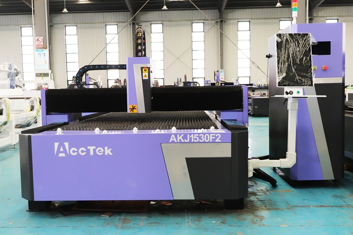
How To Maintain Laser Cutting Machines?
Laser cutting machines are widely used in modern manufacturing because of their high precision, fast processing speed, flexibility, and ability to produce complex shapes with consistent quality. However, like any advanced industrial equipment, laser cutting machines require regular maintenance to maintain stable performance and avoid unnecessary downtime. Proper maintenance not only helps preserve cutting accuracy and efficiency but also extends the service life of important components and reduces the risk of unexpected repairs.
Laser cutting machines consist of several systems that work together, including the laser source, cutting head, optical components, motion system, guide rails, transmission components, cooling system, gas supply system, electrical system, dust extraction system, and control software. Dust, smoke, metal particles, heat, vibration, and continuous operation can gradually affect these components. If maintenance is neglected, operators may experience unstable cutting quality, reduced cutting speed, inaccurate positioning, overheating, abnormal machine movement, increased consumable costs, or even equipment failure.
Effective maintenance should therefore combine routine cleaning, inspection, lubrication, calibration, consumable replacement, cooling-system care, and monitoring of key operating conditions. Some tasks should be performed daily, while others may be required weekly, monthly, quarterly, or annually depending on machine type, workload, operating environment, and manufacturer recommendations. Preventive maintenance is usually more economical than waiting until a fault causes production to stop.
This article explains how to maintain laser cutting machines systematically, covering the major components, recommended maintenance procedures, inspection schedules, common warning signs, and practical methods for preventing premature wear. Whether the machine is used for occasional fabrication or continuous industrial production, establishing a structured maintenance program can help ensure reliable operation, consistent cutting quality, improved safety, lower operating costs, and a longer overall machine lifespan.
Table of Contents
Understand the Main Systems That Require Maintenance
Laser cutting machines are made up of several mechanical, optical, electrical, cooling, gas-delivery, and control systems that must work together accurately. Maintenance should therefore not focus on only one component, such as the cutting head or laser source. Problems in one system can quickly affect the performance of other parts of the machine and ultimately reduce cutting quality, productivity, and equipment reliability.
For example, contaminated optical components may reduce laser transmission efficiency, unstable cooling systems may cause overheating, insufficient lubrication can increase motion resistance, and poor assist-gas delivery can result in excessive slag or incomplete cutting. Similarly, electrical faults or extraction-system problems can cause unexpected machine stoppages or create unsafe operating conditions.
Understanding the major systems that require maintenance makes it easier to establish an effective preventive maintenance program. Operators should know which components need regular cleaning, inspection, lubrication, calibration, replacement, or performance monitoring. The required maintenance frequency will depend on the machine configuration, production intensity, processed materials, operating environment, and recommendations from the equipment manufacturer.
The main systems that normally require regular maintenance include the laser source, laser cutting head, optical system, motion and transmission system, cooling system, assist gas system, CNC and electrical system, worktable, and extraction system.
Laser Source
The laser source is one of the most important and expensive components of laser cutting machines. It generates the laser beam used for cutting, so its condition directly influences output power, cutting stability, efficiency, and overall machine performance. Modern fiber laser sources generally require less routine maintenance than traditional CO2 laser sources, but they still need regular inspection and proper operating conditions.
Operators should keep the laser source and its surrounding area clean and free from excessive dust, moisture, oil mist, and metal particles. Ventilation openings, air filters, and cooling passages should be inspected regularly to prevent heat accumulation. The operating temperature and humidity should remain within the manufacturer’s recommended range because excessive heat or condensation can damage sensitive internal components.
Cooling-water temperature, flow rate, and cleanliness are also important because many laser sources depend on a water chiller for temperature control. Abnormal cooling conditions can trigger alarms, reduce laser output, or shorten component life.
Operators should monitor laser power stability and pay attention to unusual alarms, unexpected power reductions, abnormal noises, or repeated shutdowns. Internal servicing of the laser source should normally be performed only by qualified technicians because improper disassembly can damage high-value components and may create electrical or optical safety hazards.
Laser Cutting Head
The laser cutting head directs and focuses the laser beam onto the workpiece. Because it operates close to the cutting zone, it is constantly exposed to smoke, dust, sparks, molten metal, and high temperatures. For this reason, the cutting head is one of the components that requires the most frequent inspection and cleaning.
Protective lenses should be checked regularly for contamination, discoloration, scratches, cracks, or burn marks. A dirty or damaged protective lens can absorb laser energy, reduce cutting efficiency, cause overheating, and potentially damage more expensive optical components inside the cutting head.
The nozzle should also be inspected for deformation, slag buildup, blockage, or wear. Damaged nozzles can disturb assist-gas flow and negatively affect cutting quality. Operators should ensure that the nozzle is properly centered relative to the laser beam and that the correct nozzle size is used for the selected cutting process.
The capacitive height-sensing system should remain clean and correctly calibrated so the cutting head can maintain an appropriate distance from the workpiece. Collisions, contamination, or incorrect calibration can lead to unstable cutting height.
Connections for cooling water, assist gas, sensors, and electrical cables should also be checked for leaks, looseness, or damage. Keeping the cutting head clean and correctly aligned helps maintain stable focus, accurate cutting, and reliable piercing performance.
Optical System
The optical system transfers, shapes, and focuses the laser beam before it reaches the material. Depending on the type and design of the laser cutting machine, it may include protective windows, collimating lenses, focusing lenses, mirrors, beam-delivery components, or optical fibers.
Optical surfaces are extremely sensitive to contamination. Even small amounts of dust, smoke residue, fingerprints, moisture, or oil can absorb laser energy and create localized heating. Over time, this may damage the optical coating, reduce beam quality, or cause expensive optical failures.
Protective optical components should therefore be inspected according to operating conditions and production intensity. Cleaning should be carried out only with appropriate optical cleaning materials and methods. Operators should avoid touching optical surfaces directly.
The optical path and focus position should also be checked when cutting performance suddenly decreases or when the machine produces inconsistent kerf width, excessive slag, poor edge quality, or difficulty piercing materials that were previously processed without problems.
For fiber laser cutting machines, the optical fiber cable and connectors should be protected from excessive bending, impact, contamination, and mechanical stress. Maintaining a clean and correctly aligned optical system ensures efficient laser transmission and helps preserve cutting performance.
Motion and Transmission System
The motion and transmission system controls the movement of the cutting head or worktable along the machine axes. It typically includes linear guide rails, racks and pinions, ball screws, bearings, gearboxes, motors, couplings, belts, and other mechanical components.
These parts must move smoothly and accurately to maintain positioning accuracy and cutting precision. Dust, metal particles, insufficient lubrication, loose fasteners, worn gears, or damaged bearings can increase friction and cause vibration, backlash, abnormal noise, or positioning errors.
Guide rails and racks should be cleaned regularly to remove accumulated dust and debris. Lubrication should be applied according to the manufacturer’s recommendations using the correct type and quantity of lubricant. Automatic lubrication systems should also be checked to ensure that lubricant is reaching the required components.
Operators should inspect racks, gears, belts, couplings, and fasteners for looseness, wear, or damage. Servo motors and drive systems should be monitored for abnormal vibration, overheating, noise, or positioning alarms.
Machine accuracy should also be checked periodically, particularly after long production periods, collisions, maintenance work, or relocation. Proper maintenance of the motion system helps preserve smooth movement, cutting accuracy, high-speed performance, and long-term mechanical reliability.
Cooling System
The cooling system removes heat from critical components such as the laser source and cutting head. Stable temperature control is essential because excessive heat can reduce laser stability, damage optical components, trigger alarms, or shorten equipment life.
Most industrial laser cutting machines use a dedicated water chiller. Operators should regularly check coolant level, temperature, pressure, and flow rate. Any abnormal change may indicate leakage, blockage, pump problems, contamination, or insufficient coolant.
The coolant should be kept clean and replaced according to the manufacturer’s recommended schedule. Distilled or deionized water and approved additives may be required depending on the machine configuration. Using unsuitable water can lead to mineral buildup, corrosion, algae growth, or reduced heat-transfer efficiency.
Filters, strainers, cooling channels, and heat exchangers should also be inspected and cleaned periodically. Cooling-water hoses and fittings should be checked for leaks, cracks, aging, or loose connections.
During cold weather, operators should also prevent the cooling water from freezing, particularly if the machine is shut down overnight or stored in an unheated facility. Reliable cooling helps maintain stable laser output and protects expensive machine components from thermal damage.
Assist Gas System
Assist gases such as oxygen, nitrogen, or compressed air are used during laser cutting to remove molten material from the kerf, support the cutting reaction, cool the cutting zone, and influence edge quality. Stable gas pressure, flow, and purity are therefore important for consistent cutting performance.
Operators should inspect gas lines, regulators, valves, fittings, pressure gauges, filters, and connectors for leaks or damage. Even small leaks can increase gas consumption, reduce pressure at the nozzle, and raise operating costs.
Gas pressure should be checked against the cutting parameters for the material and thickness being processed. Unstable or insufficient pressure can cause excessive slag, incomplete cutting, poor edge quality, or reduced cutting speed.
When compressed air is used, the air-treatment system deserves particular attention. Moisture, oil, or particles in compressed air can contaminate the cutting head or reduce cutting quality. Air dryers, filters, oil separators, and drainage systems should therefore be maintained regularly.
Gas purity should also meet process requirements. Contaminated or low-purity gas may affect oxidation, discoloration, cutting speed, or surface finish. Maintaining the assist-gas system helps ensure stable cutting results while reducing unnecessary gas consumption.
CNC and Electrical System
The CNC and electrical system controls machine movement, laser operation, cutting parameters, sensors, safety functions, and communication between different machine components. Although these systems contain fewer mechanical wear parts, they still require regular inspection.
Electrical cabinets should be kept clean, dry, and properly ventilated. Cooling fans, air-conditioning systems, and filters should be inspected frequently because dust buildup can restrict airflow and cause electronic components to overheat.
Electrical terminals, connectors, cables, grounding points, and communication lines should be checked periodically for looseness, corrosion, overheating, or physical damage. Moving cables inside drag chains should also be inspected for wear, cracking, or excessive bending.
Operators should monitor the CNC system for error messages, abnormal axis behavior, communication faults, sensor problems, or software instability. Important cutting programs, parameter settings, calibration data, and machine configurations should be backed up regularly.
Software and firmware updates should be carried out carefully and normally according to manufacturer guidance. Safety circuits, emergency-stop buttons, limit switches, protective doors, and interlocks should also be tested periodically to confirm proper operation.
Well-maintained CNC and electrical systems improve machine reliability, reduce unexpected shutdowns, and support safe and accurate operation.
Worktable and Extraction System
The worktable supports the material during cutting and is directly exposed to slag, molten metal, sparks, dust, and debris. Over time, this buildup can interfere with material positioning, reduce airflow, increase fire risk, and make machine cleaning more difficult.
Slats or support bars should be inspected and cleaned regularly. Severely worn, bent, or damaged slats should be replaced because uneven support can affect workpiece stability and cutting accuracy. Accumulated slag should be removed before it becomes excessive.
Scrap pieces and small cut parts should also be cleared from the cutting area and collection trays. If debris builds up below the worktable, it can obstruct extraction airflow and increase the possibility of ignition.
The extraction system removes smoke, dust, and airborne particles generated during cutting. Ducts, filters, fans, dampers, dust collectors, and spark-control devices should therefore be inspected regularly. Blocked filters or ducts can significantly reduce extraction efficiency.
Filter elements should be cleaned or replaced according to pressure-drop indicators, operating hours, and manufacturer recommendations. Dust collection containers should be emptied before they become overloaded.
Keeping the worktable and extraction system clean improves airflow, machine cleanliness, operator visibility, workplace air quality, and fire safety.
Maintaining laser cutting machines requires attention to several interconnected systems rather than focusing on individual components in isolation. The laser source must operate under stable thermal and environmental conditions, while the cutting head and optical system must remain clean, correctly aligned, and free from contamination. The motion and transmission system requires regular cleaning, lubrication, and mechanical inspection to preserve positioning accuracy and smooth movement.
The cooling system must provide consistent temperature control, while the assist-gas system should maintain proper gas pressure, purity, and flow. CNC and electrical components need clean operating conditions, secure connections, reliable cooling, and regular safety checks. At the same time, the worktable and extraction system should be kept free from excessive slag, scrap, dust, and smoke buildup.
Understanding how these systems interact makes preventive maintenance more effective. Regular inspection and timely servicing can help identify minor problems before they develop into serious failures. By maintaining every major system according to manufacturer recommendations and actual operating conditions, manufacturers can achieve more consistent cutting quality, reduce unplanned downtime, extend machine service life, improve workplace safety, and control long-term operating costs.
Establish Preventive Maintenance Schedules
Preventive maintenance schedules help ensure that laser cutting machines remain clean, accurate, efficient, and reliable throughout daily production. Instead of waiting for faults to occur, preventive maintenance identifies potential problems before they lead to machine downtime, poor cutting quality, higher operating costs, or damage to expensive components. Well-structured schedules also make maintenance responsibilities easier to manage because operators and technicians know which tasks should be completed and how often they should be performed.
Maintenance frequency should be based on several factors, including machine type, laser power, operating hours, production intensity, processed materials, working environment, and manufacturer recommendations. Machines operating continuously in a dusty fabrication workshop will normally require more frequent cleaning and inspection than a machine used only occasionally in a clean environment.
Preventive maintenance should cover the cutting head, protective lenses, nozzles, guide rails, racks, lubrication system, chiller, gas supply, electrical cabinet, extraction system, worktable, safety devices, and other major components. Maintenance records should also be kept so that recurring problems, component wear, consumable replacement, and service intervals can be tracked over time.
The following maintenance intervals provide a practical framework for establishing systematic laser cutting machine maintenance programs. Exact procedures and intervals should always be adjusted according to the machine manufacturer’s requirements and actual operating conditions.
Daily Maintenance
Daily maintenance focuses on components that are exposed directly to cutting smoke, dust, sparks, molten metal, and continuous machine movement. These tasks are normally completed before production begins, during shift changes, or after the machine has stopped for the day.
Operators should inspect the protective lens in the cutting head and check for dust, discoloration, burn marks, scratches, or other contamination. A contaminated protective lens should be cleaned or replaced promptly because it can reduce laser transmission efficiency and may damage more expensive optical components.
The cutting nozzle should be inspected for slag buildup, deformation, blockage, or damage. The nozzle opening should remain clean and correctly centered relative to the laser beam. Cutting-head height sensing should also be checked if the machine shows unstable following height or unusual movement close to the workpiece.
The worktable should be cleared of loose scrap, slag, and finished parts. Excessive buildup under the cutting area should be removed because it can restrict extraction airflow and increase the risk of fire.
Operators should check the water chiller for correct temperature, water level, pressure, and alarm status. Assist-gas pressure should also be confirmed before production begins.
Guide rails and exposed transmission surfaces should be visually inspected for contamination or debris. The machine should also be observed for abnormal noise, vibration, smell, leakage, or movement during startup and operation.
Daily maintenance should finish with a general inspection of safety devices, emergency stops, protective covers, and the surrounding work area.
Weekly Maintenance
Weekly maintenance involves a more detailed inspection and cleaning of systems that may accumulate dust, slag, or wear during several days of production.
Guide rails, racks, gears, and exposed mechanical transmission components should be cleaned carefully. Dust and metal particles should not be allowed to accumulate because they can increase friction and accelerate mechanical wear. Operators should verify that lubrication points are receiving sufficient lubricant and that automatic lubrication systems are functioning correctly.
The extraction system should be inspected for reduced airflow, excessive dust accumulation, or abnormal fan noise. Dust collection containers should be emptied when necessary, and accessible filters should be checked for blockage.
Cooling-system filters, air filters, and ventilation openings should also be examined. Dust on heat exchangers, ventilation screens, or electrical cabinet filters can reduce cooling efficiency and cause temperatures to rise.
Assist-gas hoses, fittings, regulators, and connections should be checked for visible damage or signs of leakage. Compressed-air systems should be drained if moisture has accumulated in filters or separators.
The cutting head should receive a more thorough visual inspection, including cables, water hoses, gas connections, sensor components, and protective covers. Operators should also inspect cable chains for loose, damaged, or twisted cables.
Weekly maintenance is a good opportunity to review the overall condition of the machine and identify minor issues that may not yet affect production but could develop into larger faults if ignored.
Monthly Maintenance
Monthly maintenance should include a more comprehensive mechanical, electrical, optical, and cooling-system inspection. This interval is particularly important for machines running several shifts per day.
Operators or maintenance personnel should inspect guide rails, racks, pinions, bearings, couplings, belts, and other drive components for wear, looseness, or abnormal movement. Fasteners around moving assemblies should be checked because vibration over time can cause some connections to loosen.
The lubrication system should be inspected in detail. Lubricant levels should be checked, distribution lines should be examined for blockage or leakage, and lubrication points should be confirmed to receive the correct quantity of oil or grease.
The cooling system should be inspected for leaks, contamination, hose deterioration, and abnormal pump operation. Chiller filters and ventilation areas should be cleaned where required.
Electrical cabinets should be inspected for excessive dust, loose wiring, abnormal odors, signs of overheating, or damaged cooling fans. Filters and fans should be cleaned or replaced if airflow is restricted. Electrical work should only be performed by qualified personnel.
The optical and cutting systems should also be checked for signs of reduced performance. If cutting quality has gradually deteriorated, technicians should evaluate protective optics, focus position, nozzle centering, beam condition, and height-control accuracy.
Monthly maintenance should also include a more thorough cleaning of the worktable, slag collection areas, extraction ducts, and dust-removal components.
Quarterly Maintenance
Quarterly maintenance provides an opportunity to examine systems that do not require frequent adjustment but may gradually lose accuracy or efficiency over several months of operation.
Machine positioning accuracy, repeatability, gantry alignment, and axis movement should be checked. If the machine has experienced collisions, unusual vibration, or declining dimensional accuracy, calibration may be required.
Transmission components should be inspected more carefully for backlash, uneven wear, gear damage, bearing condition, or abnormal clearance. Servo motors, gear reducers, racks, pinions, and couplings should be evaluated for smooth operation.
The cutting head should be examined for mechanical damage and contamination. Focus calibration, nozzle alignment, capacitive sensing, and optical condition should be verified where appropriate.
The cooling system may require more extensive cleaning depending on water quality and environmental conditions. Filters, strainers, heat exchangers, pumps, and water lines should be checked for contamination or reduced flow.
Extraction ducts and filtration systems should also be inspected thoroughly. Dust buildup inside ducts can reduce extraction performance even when the main filter appears acceptable.
Electrical terminals, grounding connections, safety circuits, sensor connections, and cabinet ventilation should be checked by qualified personnel. Backup copies of CNC parameters, cutting databases, machine settings, and important production programs should also be verified.
Quarterly maintenance is particularly useful for identifying gradual mechanical and electrical changes that daily and weekly inspections may not reveal.
Semiannual Maintenance
Semiannual maintenance generally involves deeper servicing of components that experience long-term wear but do not require monthly replacement or adjustment.
The machine’s mechanical accuracy should be evaluated comprehensively. Technicians should check axis straightness, gantry squareness, positioning accuracy, repeatability, backlash, and overall machine geometry where necessary.
Transmission components such as racks, gears, reducers, bearings, belts, and couplings should be inspected for wear and replaced if their condition is beginning to affect motion quality. Lubrication lines and pumps should be tested to make sure lubricant reaches all critical points.
The water chiller should receive more extensive maintenance. Depending on manufacturer instructions, this may include cleaning internal filters, inspecting pumps, cleaning condenser surfaces, checking refrigerant-related performance, and replacing cooling water.
Electrical cabinets should be cleaned thoroughly with appropriate procedures. Cooling fans, air-conditioning units, filters, relays, terminals, contactors, and power connections should be inspected for overheating, looseness, or aging.
Extraction filters may require replacement depending on operating hours and pressure differential. Fans and ducting should be examined for wear or accumulated material.
The condition of the laser source should also be reviewed. Technicians should check historical alarms, output stability, cooling performance, and operating parameters. Any repeated laser-source faults should be investigated rather than reset.
Semiannual service can help restore machine performance before accumulated wear begins to noticeably affect production quality or reliability.
Annual Maintenance
Annual maintenance should be the most comprehensive planned service of the year. It often requires qualified maintenance technicians or authorized service personnel, especially when advanced calibration, electrical testing, laser-source inspection, or internal component servicing is necessary.
The entire machine should be evaluated for mechanical accuracy, structural condition, electrical reliability, cooling performance, laser output stability, optical performance, and safety-system operation.
Motion systems should be inspected for wear, backlash, alignment, lubrication quality, and bearing condition. Worn racks, pinions, belts, couplings, seals, or other components should be replaced where necessary.
Cooling water, filters, and serviceable cooling components should be replaced or cleaned according to manufacturer requirements. Chiller performance should be checked under operating load.
The extraction system should receive a complete inspection, including filters, ductwork, fans, valves, spark-control devices, and collection units.
Electrical cabinets should be checked for loose terminals, degraded wiring, worn contactors, damaged fans, aging components, and overheating. Grounding and protective devices should be tested.
Machine accuracy should be verified using appropriate measuring tools. Focus calibration, cutting-head alignment, height sensing, and other key process settings should also be confirmed.
The annual service should include a review of maintenance records. Recurring alarms, frequently replaced consumables, abnormal component wear, and unexpected downtime can reveal patterns that may require changes to operating procedures or future maintenance intervals.
Maintenance Based on Operating Hours
Calendar-based maintenance is useful, but operating hours can provide a more accurate indication of machine usage. Two laser cutting machines operating in different production environments may require very different maintenance intervals even if they were installed on the same date.
Machines used for one shift per day will accumulate wear more slowly than a machine operating continuously across two or three shifts. For this reason, manufacturers may specify maintenance tasks after a certain number of operating hours, laser emission hours, chiller hours, or motion-system cycles.
Operating-hour maintenance may include lubricant replacement, filter replacement, chiller service, fan replacement, pump inspection, drive-system inspection, optical inspection, or laser-source servicing. Certain consumable or mechanical parts may also have recommended service lives based on operating hours rather than calendar intervals.
Operators should track both total machine power-on hours and actual cutting hours where possible. Machines may remain powered on for long periods without cutting, while another may operate under continuous high-load production. Both conditions affect different machine components in different ways.
Maintenance intervals should also be shortened when operating conditions are severe. High dust levels, high ambient temperatures, frequent thick-plate cutting, intensive oxygen cutting, heavy slag generation, and continuous production may accelerate contamination and component wear.
Using operating hours together with daily, weekly, monthly, and annual schedules creates a more flexible and accurate preventive maintenance program. Maintenance management software, CNC service counters, or written maintenance logs can be used to record operating hours and generate service reminders.
Establishing a preventive maintenance schedule helps convert machine maintenance from a reactive repair activity into a planned part of production management. Daily maintenance focuses on cleaning, basic inspection, consumables, cooling conditions, gas pressure, and immediate safety concerns. Weekly maintenance provides deeper cleaning and inspection of transmission, extraction, lubrication, and gas-delivery systems. Monthly and quarterly maintenance place greater emphasis on component wear, electrical condition, machine accuracy, cooling performance, and system calibration.
Semiannual and annual maintenance allow technicians to perform more detailed inspections, replace aging components, verify machine geometry, service major systems, and evaluate long-term performance. Maintenance based on operating hours adds another level of control by adjusting service intervals according to actual machine usage rather than relying only on calendar dates.
The most effective schedule combines all of these intervals and adapts them to production intensity, operating environment, machine configuration, and manufacturer recommendations. Maintenance activities should be documented consistently so that component wear, repeated alarms, repairs, and replacements can be tracked over time.
By following a structured preventive maintenance schedule, manufacturers can reduce unexpected downtime, maintain cutting accuracy, extend component service life, improve production safety, control maintenance costs, and keep the laser cutting machine operating reliably throughout its working life.
Perform Daily Laser Cutting Machine Maintenance
Daily maintenance is the foundation of reliable laser cutting machine operation. Because the machine is exposed to smoke, dust, slag, molten metal, heat, vibration, and continuous mechanical movement during production, minor problems can develop quickly if they are not discovered early. A short inspection before startup and a thorough cleaning after production can prevent many common failures and help maintain stable cutting quality.
Daily maintenance should focus on the parts that experience the most direct exposure to the cutting process, including the cutting head, protective lens, nozzle, worktable, assist gas system, water chiller, and dust extraction system. Operators should also pay attention to unusual sounds, vibration, alarms, leakage, and changes in cutting behavior.
These checks do not usually require complicated disassembly. Most can be completed visually or through basic operating observations. However, if an abnormal condition is found, operators should stop the machine when necessary and allow qualified maintenance personnel to investigate the cause.
Consistent daily maintenance routines can reduce unexpected downtime, protect high-value components, improve machine cleanliness, and provide early warning of developing faults. The following maintenance tasks should be incorporated into normal laser cutting machine operation.
Inspect the Machine Before Startup
Before starting the laser cutting machine, the operator should perform a general visual inspection of the equipment and surrounding work area. This step helps identify obvious problems before the machine begins high-speed movement or laser emission.
Check that there are no tools, scrap pieces, loose parts, or other objects left on the worktable, guide rails, machine enclosure, or moving areas. Foreign objects can interfere with axis movement, damage the cutting head, or create a collision hazard.
Inspect the machine for visible oil, water, or gas leaks. Cooling hoses, lubrication lines, pneumatic connections, and assist-gas fittings should appear secure and undamaged. Any unusual leakage should be investigated before production starts.
Protective covers, access doors, guards, and enclosure panels should be properly installed. Emergency-stop buttons, safety interlocks, warning lights, and other safety devices should be in normal condition.
The operator should also check the status of the CNC system, laser source, chiller, gas supply, and extraction equipment after power-up. Any fault codes or warning messages should be resolved rather than ignored.
A clean, unobstructed machine and work area provide a safer and more reliable starting point for production.
Check the Cutting Head
The cutting head is one of the most important components to inspect every day because it operates directly above the cutting zone and is exposed to smoke, sparks, dust, and molten material.
The nozzle should be checked for slag buildup, deformation, blockage, or physical damage. A damaged or dirty nozzle can disturb assist-gas flow and cause problems such as poor edge quality, excessive slag, unstable piercing, or incomplete cutting.
The protective lens should also be inspected for contamination, discoloration, burn marks, scratches, or cracks. Even minor contamination can absorb laser energy and increase the temperature of the lens. If contamination becomes severe, it can damage internal optical components.
The nozzle should be correctly centered relative to the laser beam. If nozzle centering is incorrect, gas flow may become uneven and cutting quality may deteriorate, especially when processing thicker material.
The capacitive height-sensing system should also be checked. The cutting head should maintain a stable distance from the workpiece during operation. Slag or contamination around the ceramic body or nozzle area can interfere with height sensing.
Operators should inspect water lines, gas lines, fiber connections, cables, and connectors around the cutting head for looseness or damage.
If the machine has experienced a cutting-head collision, the head should be inspected carefully before production continues. Nozzle alignment, focus position, and height calibration may need to be checked again.
Check the Water Chiller
The water chiller regulates the temperature of the laser source and, on many machines, the cutting head or optical components. Stable cooling is essential for consistent laser output and reliable operation.
Before production begins, operators should confirm that the chiller starts normally and does not display alarms. The cooling-water temperature should remain within the range recommended by the machine or laser manufacturer.
The water level should also be checked. If the coolant level is too low, flow may become insufficient and critical components may overheat. A sudden drop in water level may indicate a leak somewhere in the cooling circuit.
Cooling-water pressure and flow should remain stable. If the machine includes flow indicators, operators should confirm that they show normal operation. Reduced flow may be caused by clogged filters, blocked hoses, pump problems, or contamination inside the cooling circuit.
Inspect cooling hoses and fittings for leakage, cracking, loosening, or aging. Water leakage near electrical equipment requires immediate attention.
The chiller’s air intake and exhaust areas should also remain unobstructed. Dust buildup around the condenser or ventilation openings can reduce cooling efficiency and cause the chiller to work harder.
Regular daily observation of the chiller helps prevent overheating-related alarms and protects the laser source from thermal damage.
Check the Assist Gas Supply
Assist gas plays an important role in removing molten material from the cutting kerf and maintaining stable cutting performance. Oxygen, nitrogen, or compressed air may be used depending on the material, thickness, and cutting process.
Before production begins, operators should verify that the correct assist gas is connected and that sufficient supply is available for the planned work. Gas cylinders, bulk tanks, compressors, or generation systems should have adequate pressure and capacity.
The pressure displayed at regulators and machine control interfaces should be checked for stability. If pressure fluctuates significantly, cutting quality can become inconsistent.
Inspect gas hoses, fittings, valves, regulators, and connectors for signs of leakage or damage. Leaks increase operating costs and may prevent the cutting head from receiving sufficient pressure.
When compressed air is used, moisture separators, filters, and dryers should be checked. Water or oil entering the assist-gas line can contaminate optical components and negatively affect cutting performance.
Operators should also pay attention to sudden increases in gas consumption. Excessive consumption may indicate a leak, incorrect pressure setting, damaged nozzle, or unsuitable cutting parameters.
Maintaining a stable assist-gas supply helps ensure consistent kerf formation, reliable slag removal, and predictable cutting quality.
Clean the Cutting Worktable
The cutting worktable is continuously exposed to sparks, slag, small cut parts, and molten material. Without regular cleaning, debris can accumulate quickly and interfere with production.
Loose scrap pieces should be removed from the worktable every day. Small parts may fall between support slats and become trapped underneath. If they remain in the machine, they can interfere with moving parts, extraction airflow, or automatic pallet-changing systems.
Support slats should be inspected for excessive slag buildup. Thick deposits can create uneven material support and increase the possibility of reflected laser energy or localized overheating.
Bent, badly damaged, or heavily worn slats should be identified for replacement. Uneven support can cause thin sheets to deform or sit incorrectly, which may affect focus distance and cutting accuracy.
The area below the worktable should also be checked. Scrap collection trays, slag drawers, or waste containers should be emptied before they become overloaded.
Excessive accumulation of combustible dust, coatings, or fine particles should be avoided because hot slag or sparks can create a fire risk.
Keeping the worktable clean improves material support, extraction efficiency, and overall machine safety.
Check the Dust Extraction System
The dust extraction system removes smoke, fine particles, fumes, and airborne contaminants generated during laser cutting. Efficient extraction keeps the machine cleaner and improves the working environment.
Before production starts, operators should confirm that the extraction fan operates normally. Unusual noise, weak airflow, or abnormal vibration may indicate fan wear, blockage, or mechanical problems.
Airflow around the cutting zone should be checked during operation. If smoke remains inside the enclosure for longer than usual, extraction performance may have decreased.
Dust collection containers should be inspected and emptied when necessary. Overfilled containers can reduce extraction efficiency and increase fire risk.
Filters should be monitored for excessive dust loading. Some extraction systems include pressure-differential indicators or alarms that show when filter resistance becomes too high.
Accessible ducts, dampers, and intake openings should be checked for blockage. Slag, dust, or small scrap pieces can restrict airflow.
If the machine uses automatic sectional extraction, operators should observe whether the correct extraction zones open and close as the cutting head moves.
Maintaining good extraction performance reduces contamination inside the machine and helps protect optics, electrical components, and mechanical systems.
Listen for Abnormal Noise and Vibration
Operators should pay attention to the sound and movement of the laser cutting machine throughout the day. Experienced operators can often identify developing problems by noticing changes in normal operating noise.
During axis movement, the machine should move smoothly without grinding, knocking, squealing, or repeated impact sounds. Unusual noises may indicate inadequate lubrication, worn bearings, damaged racks or gears, loose components, foreign objects, or servo-related problems.
Abnormal vibration may appear in the gantry, cutting head, motors, fans, chiller, extraction system, or transmission components. Vibration can reduce cutting accuracy and may indicate mechanical wear or imbalance.
Changes in acceleration or movement should also be observed. Jerking, hesitation, or inconsistent motion may suggest drive-system problems, contamination on guide rails, loose couplings, or control issues.
Operators should not simply increase machine speed or adjust cutting parameters to compensate for abnormal behavior. The source of the problem should be identified.
Recording when and where abnormal noise occurs can help technicians diagnose the fault more efficiently. Details such as axis direction, cutting speed, acceleration, or operating condition can be useful during troubleshooting.
Clean the Machine After Production
Cleaning the machine after production prevents dust, slag, and debris from remaining on sensitive components overnight or accumulating over multiple shifts.
Loose scrap and finished parts should be removed from the worktable and lower collection areas. Slag deposits should be cleaned where practical, especially around areas that can affect extraction airflow or machine movement.
Guide rails, racks, protective covers, and accessible mechanical surfaces should be cleaned according to the manufacturer’s recommendations. Abrasive dust should not be allowed to remain on lubricated surfaces because it can accelerate wear.
The exterior surfaces of the cutting head should be cleaned carefully. However, optical components should only be cleaned using approved procedures and materials.
Dust should be removed from accessible ventilation openings, filters, and protective screens. Electrical cabinets should remain closed during routine cleaning unless maintenance is being performed by qualified personnel.
The machine enclosure and surrounding floor should also be cleaned. Scrap, metal dust, packaging materials, oil, and other debris should not be allowed to accumulate near the equipment.
Before shutting down, operators should review machine alarms, unusual events, or cutting problems encountered during the shift. Any issue that requires follow-up maintenance should be recorded.
A clean machine is easier to inspect, safer to operate, and less likely to suffer from contamination-related failures.
Daily laser cutting machine maintenance is primarily focused on inspection, cleanliness, operating condition, and early fault detection. Operators should inspect the machine before startup, confirm that safety devices and major systems are functioning normally, and make sure that the work area is free from obstacles and hazards.
The cutting head requires particular attention because contamination or damage to the nozzle and protective lens can quickly affect cutting quality. The water chiller should maintain correct temperature, level, pressure, and flow, while the assist-gas system must provide stable pressure and clean gas. The worktable and dust extraction system should be kept free from excessive slag, scrap, and dust accumulation.
Operators should also remain alert to abnormal noise, vibration, leakage, alarms, or changes in machine movement during production. These signs may reveal developing mechanical, electrical, cooling, or transmission problems before they lead to a complete breakdown.
Cleaning the machine at the end of production completes the daily maintenance cycle and prepares the equipment for the next shift. When these simple tasks are performed consistently and recorded properly, they can significantly reduce unexpected failures, protect expensive components, maintain cutting accuracy, improve safety, and extend the overall service life of the laser cutting machine.
Maintain the Laser Cutting Head
The laser cutting head is one of the most critical and frequently serviced parts of laser cutting machines. It is responsible for directing and focusing the laser beam onto the workpiece while also delivering assist gas and maintaining the correct distance between the nozzle and the material surface. Because the cutting head operates directly above the cutting zone, it is continuously exposed to smoke, dust, sparks, molten metal, slag, heat, and occasional mechanical impacts.
Even small amounts of contamination or minor mechanical damage can reduce cutting performance. A dirty protective lens may absorb laser energy and overheat, a damaged nozzle can disturb gas flow, an incorrectly centered nozzle can cause uneven cutting, and a damaged ceramic ring may affect capacitive height sensing. If these problems are ignored, they can lead to poor edge quality, excessive slag, unstable piercing, incomplete cutting, reduced cutting speed, or damage to expensive internal optical components.
Routine maintenance of the cutting head should therefore include exterior cleaning, protective lens inspection, nozzle inspection and replacement, nozzle centering, ceramic ring inspection, height-sensing calibration, and collision prevention. Operators should follow the equipment manufacturer’s procedures closely, especially when handling optical components. Clean working conditions, suitable tools, and proper replacement techniques are essential.
Regular cutting-head maintenance helps preserve laser transmission efficiency, assist-gas stability, focus accuracy, and reliable machine operation while reducing the risk of costly failures.
Clean the Cutting Head Exterior
The exterior of the cutting head should be kept clean because dust, smoke residue, slag particles, and oil can accumulate on its surfaces during production. Although external contamination may appear harmless, excessive buildup can interfere with sensors, connectors, cooling lines, or height-sensing components.
Before cleaning, the machine should be placed in a safe maintenance condition according to the manufacturer’s instructions. Loose dust can be removed using approved lint-free materials or other suitable cleaning methods. The operator should avoid allowing debris to enter openings around the nozzle, protective lens cartridge, electrical connectors, or gas passages.
Special attention should be paid to the lower part of the cutting head because this area is closest to the cutting process. Slag and smoke residue may accumulate around the nozzle holder, ceramic ring, and sensor surfaces.
Water hoses, gas lines, electrical cables, and fiber connections around the cutting head should also be inspected while cleaning. Any loose fittings, damaged insulation, leaking connections, or signs of heat exposure should be addressed promptly.
Harsh chemicals, abrasive materials, or uncontrolled compressed air should not be used unless specifically approved by the manufacturer. Improper cleaning can force contamination deeper into the cutting head or damage sensitive surfaces.
Keeping the exterior clean makes inspection easier and helps operators identify cracks, loose parts, contamination, or mechanical damage before these problems affect cutting performance.
Inspect the Protective Lens
The protective lens acts as a barrier between the cutting process and the more expensive focusing and collimating optics inside the cutting head. Because it is exposed to contamination from smoke, dust, molten material, and gas impurities, it requires frequent inspection.
Operators should examine the protective lens for dust, haze, discoloration, fingerprints, burn marks, scratches, cracks, or small black spots. Even minor contamination can absorb laser energy and create localized heating.
A contaminated protective lens may cause gradual reductions in cutting quality. Common signs include slower piercing, increased slag, inconsistent kerf width, reduced cutting speed, or difficulty cutting material that was previously processed successfully.
Inspection should be performed in a clean environment. The protective lens should not be touched directly with bare fingers because skin oils can contaminate the optical surface.
If the lens is only lightly contaminated and the manufacturer permits cleaning, approved optical cleaning methods should be used. However, a lens showing permanent burn marks, coating damage, deep scratches, or cracks should be replaced rather than reused.
Protective lenses should also be inspected more frequently during demanding applications such as thick-plate cutting, intensive piercing, high-power operation, or production involving heavy smoke and slag.
Frequent inspection is much less expensive than allowing a damaged protective lens to cause contamination or thermal damage to internal optical components.
Replace the Protective Lens Correctly
Replacing a protective lens requires careful handling because even a new lens can become contaminated or damaged during installation. The replacement should be performed in a clean, low-dust environment whenever possible.
Before opening the protective lens cartridge, the operator should clean the surrounding area to prevent loose dust from entering the cutting head. Hands should be clean, and suitable gloves or finger cots should be used according to the manufacturer’s procedures.
The new protective lens should be removed from its packaging carefully without touching the optical surface. Operators should inspect it under suitable lighting to confirm that it is free from dust, scratches, coating defects, or fingerprints.
The lens should be installed in the correct orientation. Some protective lenses have coatings or structural differences that require a specific installation direction. Installing the lens incorrectly may affect transmission or durability.
The sealing ring and lens cartridge should also be inspected. Damaged seals can allow cutting smoke, dust, or gas contamination to enter the optical cavity.
The cartridge should be inserted smoothly and secured properly. Excessive force should be avoided because it can damage the lens, seal, or cartridge.
After replacement, the cutting head should be checked for normal operation. If cutting performance remains poor, technicians may need to inspect additional optical components, focus settings, nozzle alignment, or gas delivery.
Correct replacement procedures help ensure that a new protective lens provides maximum service life and protects the more expensive optics inside the cutting head.
Inspect and Clean the Nozzle
The cutting nozzle directs assist gas into the cutting kerf and helps maintain controlled gas flow around the laser beam. Its condition has a significant influence on piercing, slag removal, cutting speed, edge quality, and overall process stability.
The nozzle should be inspected frequently for slag, spatter, dust, carbon deposits, or other contamination. Material buildup around the nozzle opening can restrict gas flow or cause the gas stream to become uneven.
Cleaning should be performed carefully using suitable tools that do not enlarge, scratch, or deform the nozzle opening. Sharp or oversized tools should not be forced through the nozzle because even slight dimensional changes may affect gas flow.
The nozzle surface should also be inspected for impact marks, dents, scratches, or distortion. These problems commonly occur after the cutting head contacts a tilted workpiece, raised cut part, slag accumulation, or warped sheet.
Operators should make sure that the nozzle thread and mounting surfaces remain clean. Debris in the threads can prevent the nozzle from seating correctly, leading to misalignment or height-sensing problems.
Different cutting applications may require different nozzle diameters or nozzle types. The correct nozzle should always be installed according to the cutting parameters.
A clean, undamaged nozzle supports stable gas flow and helps maintain consistent cutting performance.
Replace Damaged Nozzles
A damaged nozzle should be replaced rather than repeatedly cleaned or adjusted. Even small deformation around the nozzle opening can change the direction or distribution of assist gas and reduce process stability.
Signs that replacement may be necessary include visible dents, an oval or enlarged opening, severe scratches, damaged threads, persistent slag buildup, or repeated nozzle-centering problems.
Cutting performance can also indicate nozzle damage. Excessive slag, uneven cutting edges, unstable piercing, inconsistent cuts on different sides of a contour, or abnormal gas consumption may be related to nozzle condition.
Replacement nozzles should match the cutting head model, diameter, layer configuration, and intended cutting process. Using an unsuitable nozzle can lead to poor gas flow and unstable cutting even if the nozzle is new.
Before installing the replacement, the nozzle holder and threads should be cleaned. The nozzle should be installed straight and tightened according to the manufacturer’s requirements. Over-tightening should be avoided because it may damage the ceramic ring, threads, or nozzle assembly.
After replacement, nozzle centering should be checked before normal production resumes.
Nozzles are relatively inexpensive consumables compared with the potential cost of poor cutting quality or cutting-head damage. Timely replacement is therefore an important part of preventive maintenance.
Check Nozzle Centering
Nozzle centering ensures that the laser beam passes through the center of the nozzle opening. Correct alignment is essential because the nozzle also directs assist gas around the beam and into the cutting kerf.
If the beam is off-center, one side of the nozzle may become hotter than the other, and gas distribution may become uneven. This can cause poor edge quality, excessive slag, unstable piercing, inconsistent kerf formation, or premature nozzle damage.
Nozzle centering should be checked after nozzle replacement, cutting-head collisions, ceramic ring replacement, optical maintenance, or whenever cutting quality becomes uneven.
Many laser cutting machines include a nozzle-centering procedure using adhesive tape, a calibration target, a camera, or other manufacturer-specific methods. Operators should follow the approved procedure rather than estimating alignment visually.
The beam mark should appear centered relative to the nozzle opening. If adjustment is required, the centering mechanism should be changed gradually until the beam and nozzle are properly aligned.
Different nozzle diameters may make centering errors more noticeable. Small-diameter nozzles generally require greater alignment accuracy.
After centering, a test cut should be performed to verify stable gas flow and consistent cutting quality.
Regular nozzle-centering checks help maintain predictable performance and prevent unnecessary wear on the nozzle and optical system.
Inspect the Ceramic Ring
The ceramic ring, sometimes called the ceramic body or ceramic holder, forms part of the cutting-head assembly and plays an important role in nozzle mounting and capacitive height sensing.
Because it is positioned close to the workpiece, the ceramic ring can be damaged by cutting-head collisions, excessive heat, slag, or mechanical stress. Cracks, chips, loose connections, or contamination can interfere with electrical sensing and cause unstable height control.
The ceramic ring should be inspected visually during routine cutting-head maintenance. Operators should look for hairline cracks, broken edges, burn marks, loose metal components, contamination, or damaged threads.
If the ceramic ring becomes cracked, the height-sensing system may provide inaccurate readings. This can cause the nozzle to move too close to the material or remain too far above it. In severe cases, unstable sensing can lead to repeated collisions.
The electrical contact surfaces associated with capacitive sensing should remain clean and properly connected. Dirt or oxidation may affect signal stability.
A damaged ceramic ring should be replaced promptly using the correct component specified for the cutting head.
After replacement, nozzle centering and height calibration may need to be performed again. Proper ceramic ring condition supports reliable nozzle positioning and stable automatic height control.
Calibrate the Height-Sensing System
The height-sensing system maintains the correct distance between the nozzle and the workpiece during cutting. Most modern laser cutting heads use capacitive sensing to measure this distance continuously.
Correct nozzle height is important because it affects assist-gas flow, focus relationship, piercing stability, and cutting quality. If the nozzle is too high, gas effectiveness may decrease. If it is too low, the cutting head may collide with the material.
Calibration should be performed according to manufacturer instructions, particularly after nozzle replacement, ceramic ring replacement, cutting-head repair, collision, or significant changes in machine setup.
Before calibration, the nozzle, ceramic ring, and workpiece surface should be clean. Slag, rust, oil, protective film, or debris can interfere with capacitive sensing.
The calibration process allows the control system to establish the relationship between the sensor signal and actual nozzle-to-material distance. Once calibrated, the machine should be tested to confirm that the cutting head follows the workpiece surface smoothly.
Operators should watch for signs of height-control problems, including repeated head movement, unexpected lifting, unstable following distance, contact with the sheet, or inconsistent cutting quality.
If calibration repeatedly fails, technicians should investigate the ceramic ring, nozzle, sensor cable, grounding, material surface, or control system.
Proper height calibration protects the cutting head and helps maintain stable processing conditions.
Prevent Cutting-Head Collisions
Cutting-head collisions are among the most common causes of nozzle, ceramic ring, and cutting-head damage. They can also affect alignment, height sensing, focus position, and mechanical accuracy.
One major cause is material deformation. Thin sheets may warp because of heat, while poorly supported material can bend upward during cutting. Cut parts may also tip or lift after separation and enter the cutting-head travel path.
Operators should ensure that sheets are positioned flat on the worktable before cutting begins. Severely warped material should be corrected or replaced whenever possible.
Cutting sequences should be optimized to reduce the chance that small parts will tip upward. Micro-joints, suitable lead-ins, proper cutting order, and nesting strategies can help keep parts stable.
Support slats should be maintained so that the material remains level. Excessive slag accumulation or damaged slats can create uneven support.
The height-sensing system must also remain properly calibrated. Incorrect sensing may cause the nozzle to travel too close to the material surface.
Rapid movement across areas containing loose or raised parts should be avoided where practical. Operators should also monitor the first production cycle after loading unfamiliar material or a new nesting program.
If a collision occurs, the nozzle, ceramic ring, protective lens, centering, and height calibration should be inspected before continuing production.
Preventing collisions is far more effective than repairing the cutting head after repeated mechanical impacts.
Laser cutting head maintenance is essential because the cutting head operates in one of the harshest areas of the machine and directly influences laser delivery, assist-gas flow, focus accuracy, and nozzle-to-workpiece distance. Small problems in this assembly can quickly cause visible reductions in cutting quality or lead to damage to expensive optical components.
Routine maintenance should begin with cleaning the cutting head exterior and carefully inspecting the protective lens. Contaminated or damaged protective lenses should be cleaned or replaced using correct handling procedures to prevent further contamination. The nozzle should be kept clean and replaced whenever it becomes deformed, worn, or damaged.
Nozzle centering is equally important because the laser beam and assist-gas stream must remain properly aligned. The ceramic ring should be inspected for cracks, contamination, or electrical problems that could affect capacitive sensing. Height-sensing calibration should be performed whenever maintenance or collisions may have changed the cutting-head setup.
Operators should also take preventive measures to reduce cutting-head collisions by maintaining flat material, clean support slats, proper cutting sequences, stable height control, and suitable nesting strategies.
Consistent cutting-head maintenance helps maintain reliable piercing, smooth edge quality, accurate focus control, stable gas flow, and predictable production. It also protects expensive optical components, reduces unexpected downtime, and extends the overall service life of the laser cutting machine.
Maintain the Optical System
The optical system is responsible for transmitting, directing, shaping, and focusing the laser beam from the laser source to the workpiece. Its condition has a direct effect on laser power delivery, beam quality, focus accuracy, cutting speed, kerf consistency, and edge quality. Even small amounts of contamination on an optical surface can absorb laser energy, generate localized heat, reduce transmission efficiency, and eventually damage optical coatings.
The specific optical components used in laser cutting machines depend on the laser type and machine design. Fiber laser cutting systems commonly use protective windows, collimating lenses, focusing lenses, and optical fiber connections inside or around the cutting head. CO2 laser cutting machines may additionally use beam-delivery mirrors and other external optics to guide the laser beam from the resonator to the cutting head.
Optical maintenance requires greater care than ordinary mechanical cleaning. Dust, smoke residue, fingerprints, oil, moisture, or unsuitable cleaning materials can permanently damage sensitive surfaces. Operators should therefore maintain a clean working environment, use approved optical-cleaning supplies, and avoid unnecessary contact with optical components.
Some optical maintenance tasks can be handled by trained operators, while others should be performed by qualified technicians. Internal optics, sealed optical assemblies, beam alignment, and high-power laser components should not be disassembled without proper training and manufacturer guidance.
Regular inspection and careful handling of the optical system help preserve stable laser transmission, reduce unnecessary power loss, prevent thermal damage, and protect high-value components from premature failure.
Keep Optical Components Clean
Cleanliness is one of the most important requirements for maintaining a laser cutting machine’s optical system. Optical surfaces can become contaminated by smoke, dust, metal particles, oil mist, moisture, fingerprints, or impurities entering through the gas or air supply.
Even contamination that is difficult to see with the naked eye can affect laser transmission. When contaminants absorb laser energy, they may create hot spots on the optical surface. These hot spots can damage coatings, cause discoloration, or eventually lead to lens failure.
The area around the cutting head should therefore be kept as clean as possible. Operators should prevent dust and debris from accumulating near protective lens cartridges, optical access points, and fiber connectors.
Protective windows should be inspected regularly because they are designed to prevent contamination from reaching more expensive internal optics. If a protective window is damaged or heavily contaminated, it should be replaced promptly.
The cleanliness of assist gas and compressed air also influences optical life. Moisture, oil, or particles entering the cutting head can contaminate internal components.
Optical components should remain covered or sealed whenever they are not being serviced. Replacement lenses should stay in their original protective packaging until installation.
Maintaining a clean environment around the optical system reduces cleaning frequency, improves optical component life, and lowers the risk of sudden cutting-performance deterioration.
Handle Optical Components Properly
Optical components should always be handled with care because their surfaces and coatings are easily damaged. Improper handling can contaminate a lens before it is even installed or create scratches that reduce its service life.
Operators should never touch the optical surface directly with bare fingers. Skin oils, moisture, and residue can adhere to the coating and become difficult to remove. Suitable gloves or finger cots should be used when handling lenses, windows, and mirrors.
Optics should be held only by their edges whenever possible. They should not be placed directly on dirty workbenches, metal surfaces, or ordinary cloth.
Before opening an optical assembly, the surrounding area should be cleaned to prevent airborne dust from entering the cutting head. Tools used during optical maintenance should also be clean and dedicated to this purpose where practical.
Optical components should not be exposed to unnecessary air movement, smoke, or workshop dust. If an optic must be removed, it should be placed immediately into a clean protective container.
Operators should also avoid mixing old and new optical components during maintenance. Replacement parts should be identified clearly and checked for the correct diameter, thickness, coating, and orientation before installation.
Careful handling prevents contamination and mechanical damage and helps ensure that optical components perform as intended after maintenance.
Clean Optical Components Safely
Optical cleaning should only be performed when necessary and according to the machine or optical-component manufacturer’s instructions. Unnecessary cleaning can increase the risk of scratching or damaging coatings.
Before cleaning, operators should determine whether the component is designed to be cleaned or replaced. Some inexpensive protective lenses are more practical to replace when badly contaminated rather than repeatedly clean.
Loose dust should be removed carefully before wiping the surface. Dragging particles across an optical coating can create scratches. Approved dust-removal methods should be used rather than blowing directly on the lens with the mouth or using unfiltered workshop compressed air.
Only suitable optical-grade cleaning materials should be used. These may include lint-free optical wipes, lens tissues, approved swabs, and manufacturer-recommended cleaning solutions. Ordinary paper towels, shop cloths, abrasive materials, or unknown solvents should be avoided.
Cleaning strokes should be gentle and controlled. Excessive pressure can damage delicate coatings. A clean portion of the wipe should be used for each pass rather than repeatedly spreading contamination across the surface.
After cleaning, the optic should be inspected under suitable lighting. No streaks, particles, fingerprints, or cleaning residue should remain.
If contamination cannot be removed safely, or if the surface shows burn marks, coating damage, or scratches, replacement is usually the better option.
Safe optical cleaning preserves transmission efficiency while minimizing the risk of creating additional damage during maintenance.
Inspect Focusing Lenses
The focusing lens concentrates the laser beam onto the workpiece and determines the size and position of the focused spot. Its condition therefore has a major influence on cutting efficiency and quality.
A focusing lens should be inspected for haze, discoloration, scratches, cracks, coating damage, burn marks, or contamination. Any of these problems can affect beam transmission and focus characteristics.
Contamination on the focusing lens may cause localized heating. As temperature increases, the lens can experience thermal distortion, which may change the effective focus position and cause inconsistent cutting performance.
Signs of focusing-lens problems may include reduced cutting speed, increased slag, poor piercing, wider kerfs, unstable edge quality, or repeated focus adjustment.
In many modern cutting heads, the focusing lens is located inside a sealed optical assembly and should not be accessed casually. If a protective lens is repeatedly becoming damaged or cutting performance continues to decline after basic maintenance, qualified technicians may need to inspect the focusing optics.
When a focusing lens is removed, its orientation and mounting arrangement must be recorded and restored correctly. Incorrect installation can affect beam behavior or damage the optical system.
Focusing lenses that show permanent coating damage, severe scratches, cracks, or thermal marks should be replaced rather than reused.
Regular inspection helps prevent a deteriorating focusing lens from becoming a source of cutting instability or more extensive cutting-head damage.
Inspect Collimating Lenses
The collimating lens shapes the incoming laser beam into a controlled parallel beam before it passes through the focusing optics. In fiber laser cutting systems, the collimating optics are an important part of maintaining consistent beam geometry.
Collimating lenses are generally protected inside the cutting head, so they may require less frequent maintenance than the lower protective lens. However, contamination can still occur if seals fail, protective windows are damaged, or maintenance is performed in an unclean environment.
A contaminated collimating lens can reduce transmission efficiency and alter beam quality. It may also experience localized heating, leading to optical distortion or coating damage.
Possible signs of collimating-lens problems include unexplained loss of cutting power, difficulty achieving a stable focus, inconsistent cutting quality, or abnormal temperature in the cutting-head optics.
Inspection of collimating lenses often requires more technical disassembly than routine protective-lens maintenance. Operators should follow manufacturer procedures carefully and avoid opening sealed optical sections unless they are trained to do so.
If inspection is required, the lens should be checked for dust, haze, burn marks, scratches, and coating deterioration. Seals and surrounding components should also be examined to determine how contamination entered the optical cavity.
A damaged collimating lens should normally be replaced, and the cutting head recalibrated if necessary.
Maintaining clean collimating optics helps preserve beam consistency and reliable focus performance.
Maintain CO2 Laser Mirrors
CO2 laser cutting machines often use a series of mirrors to guide the laser beam from the resonator to the cutting head. These mirrors are critical to beam delivery and require regular inspection.
Mirror surfaces should be checked for dust, smoke residue, oxidation, discoloration, scratches, burn marks, or coating damage. Contaminated mirrors can absorb laser energy and reduce the amount of power reaching the cutting head.
Because the beam may pass through several mirrors, even small losses at each surface can combine into a noticeable reduction in cutting performance.
Mirrors should be cleaned only using procedures suitable for their coating type. Different mirror materials and coatings may require different cleaning methods, so operators should follow the manufacturer’s instructions rather than using a universal cleaning approach.
Mirror mounts should also be inspected. Loose fasteners, vibration, mechanical impact, or thermal changes can shift mirror alignment over time.
The cooling of mirrors should be maintained where applicable. Some high-power CO2 laser cutting systems use water-cooled mirror assemblies to control temperature and prevent distortion.
Damaged mirrors should be replaced promptly because a deteriorating coating can continue absorbing energy and may eventually fail.
Maintaining CO2 laser mirrors helps preserve beam transmission efficiency, stable alignment, and consistent laser power at the cutting head.
Check CO2 Beam Alignment
Correct beam alignment is essential in CO2 laser cutting machines because the laser beam must travel through multiple mirrors and reach the center of the cutting head consistently across the full machine working area.
Misalignment can occur gradually due to vibration, thermal expansion, loose mirror mounts, machine movement, mechanical impact, or maintenance work. Even small angular errors can become significant over a long beam path.
Beam alignment should be checked when cutting quality becomes inconsistent across different positions on the worktable, when laser power appears lower at certain machine locations, or after replacing or adjusting mirrors.
Alignment procedures typically involve checking the beam position at several points along the optical path. The exact method depends on machine design and should follow manufacturer instructions.
The beam should remain centered through the optical path as the machine moves across its travel range. If the beam shifts significantly, mirror adjustments may be required.
Adjustments should be made gradually because movement of one mirror can affect downstream alignment. Qualified technicians should normally perform precise beam alignment, especially on high-power systems.
After alignment, cutting performance should be tested at multiple locations on the worktable to verify consistent beam delivery.
Proper CO2 beam alignment minimizes optical losses, reduces the risk of beam clipping, and helps maintain uniform cutting quality across the machine’s full working area.
Recognize Optical-System Problems
Recognizing early signs of optical problems can prevent minor contamination or alignment issues from developing into expensive component failures.
A gradual reduction in cutting speed is one common warning sign. If previously stable cutting parameters no longer produce complete cuts, the optical system may be losing transmission efficiency.
Frequent slag, poor edge quality, unstable piercing, larger-than-normal kerf width, or inconsistent cuts can also indicate optical contamination or focus problems.
Another warning sign is the need to increase laser power repeatedly to maintain the same cutting result. Increasing power may temporarily compensate for reduced transmission, but it does not correct the underlying optical problem.
Protective lenses that fail unusually quickly may indicate contamination entering the cutting head, incorrect gas quality, damaged seals, or problems with internal optics.
Changes in focus position can also suggest thermal distortion or optical damage. If the optimum focus shifts repeatedly during production, the optical system should be inspected.
For CO2 laser cutting machines, uneven cutting quality across different areas of the table may indicate beam-alignment problems.
Visible burn marks, discoloration, cracks, or coating damage on any optical component should be treated seriously.
When optical problems are suspected, operators should inspect the simplest and most accessible components first, such as the protective lens and nozzle. If the problem remains, qualified technicians should evaluate deeper optical components rather than continuing to operate the machine under unstable conditions.
The optical system plays a central role in transferring laser energy efficiently and accurately from the source to the workpiece. Its maintenance requires careful attention because even small amounts of contamination, physical damage, or misalignment can reduce beam quality and cutting performance.
Optical components should be kept clean, handled only with appropriate protection, and serviced in a low-dust environment. Cleaning should use approved optical-grade materials and methods to avoid scratching or damaging coatings. Focusing and collimating lenses should be inspected for contamination, discoloration, burn marks, and coating deterioration, while sealed internal optics should only be accessed by trained personnel when necessary.
CO2 laser cutting machines require additional maintenance of beam-delivery mirrors and alignment. Mirror cleanliness, mounting condition, and beam position should be checked periodically to ensure stable laser transmission across the full machine working area.
Operators should also learn to recognize warning signs such as unexplained power loss, poor piercing, increased slag, inconsistent kerf width, repeated focus changes, or unusually rapid protective-lens failure. These symptoms may indicate an optical-system problem that requires inspection.
Careful optical maintenance helps maintain stable laser transmission, consistent focus, reliable cutting quality, and efficient machine operation while reducing the risk of expensive lens, mirror, or cutting-head damage.
Maintain the Laser Source
The laser source is the core component of laser cutting machines because it generates the laser beam used to perform the cutting process. Its stability directly affects cutting speed, piercing performance, edge quality, energy efficiency, and overall production reliability. Because laser sources are also among the most expensive components in the machine, proper maintenance is essential for protecting long-term equipment investment.
Maintenance requirements vary according to laser type. Fiber laser sources are generally designed with sealed optical systems and require relatively little routine internal maintenance. Their maintenance is focused mainly on cleanliness, cooling, electrical connections, operating environment, and performance monitoring. CO2 laser sources usually require more attention because their resonators, gas systems, mirrors, electrodes, vacuum components, and cooling circuits may require periodic servicing.
Operators should avoid opening or disassembling the laser source unless they are specifically trained and authorized to do so. High-power laser cutting systems contain sensitive optical components, high-voltage electrical circuits, and other parts that can be damaged by improper handling. Internal service should normally be performed by qualified technicians or according to manufacturer instructions.
Routine laser source maintenance should focus on maintaining a clean environment, stable temperature, reliable cooling, proper ventilation, and consistent operating conditions. Operators should also monitor laser output and respond promptly to alarms or changes in cutting behavior. Preventive attention to these areas can reduce unexpected shutdowns, maintain stable laser power, and extend the working life of the source.
Maintain Fiber Laser Sources
Fiber laser sources are widely used in modern metal laser cutting machines because of their high electrical efficiency, compact structure, stable beam quality, and relatively low maintenance requirements. Most industrial fiber laser sources use sealed internal optical systems, so operators generally do not need to clean or adjust internal optical components during routine maintenance.
The priority is to keep the laser source clean and properly cooled. Air intake openings, cooling vents, filters, and surrounding areas should be inspected regularly for dust accumulation. Restricted airflow can increase internal temperature and reduce reliability.
Water-cooled fiber laser sources depend heavily on stable chiller operation. Operators should monitor cooling-water temperature, flow, pressure, and quality. Cooling water should be maintained according to the laser manufacturer’s requirements because contamination, mineral buildup, corrosion, or algae can restrict internal cooling channels.
The optical fiber cable connecting the source to the cutting head should also be protected carefully. It should not be sharply bent, twisted, crushed, stepped on, or exposed to impact. Excessive bending can damage the fiber or affect beam transmission.
Electrical power should remain stable and properly grounded. Voltage fluctuations, poor grounding, or sudden power interruptions may cause alarms or damage sensitive electronic components.
Operators should also monitor operating hours, power stability, temperature readings, and alarm history. If the laser source repeatedly reports faults or produces unstable output, qualified technicians should investigate the cause instead of repeatedly resetting the system.
Maintain CO2 Laser Sources
CO2 laser sources generally require more routine maintenance than fiber laser cutting systems because they use a gas mixture and a resonator containing mirrors, electrodes, discharge components, or other optical and electrical assemblies.
Cooling is especially important. The cooling-water circuit should be checked regularly for correct temperature, flow, pressure, and cleanliness. Insufficient cooling can cause thermal distortion, unstable output, damage to resonator components, or automatic shutdown.
Depending on the laser design, the gas supply or gas mixture may require periodic inspection or replacement. Gas purity, pressure, and flow must meet manufacturer specifications. Leaks or contamination can reduce laser efficiency and cause unstable discharge behavior.
Resonator mirrors and windows may also require periodic inspection. Dust, deposits, oxidation, or coating damage can reduce optical efficiency. Cleaning or adjustment should only be performed using approved procedures because these components are highly sensitive.
High-voltage components, electrodes, vacuum pumps, blowers, and discharge systems may require servicing at specified intervals. These tasks are generally more complex and should be performed by trained technicians.
Operators should also observe whether the CO2 laser takes longer than usual to reach stable power, produces fluctuating output, or requires increasingly higher settings to achieve the same cutting result. These changes can indicate aging gas, optical contamination, alignment issues, cooling problems, or electrical deterioration.
Following the manufacturer’s recommended service intervals is particularly important for CO2 laser sources because their maintenance needs can vary significantly between designs.
Keep the Laser Source Environment Clean
The operating environment has a major influence on laser source reliability. Dust, oil mist, metal particles, smoke, humidity, and chemical vapors can enter ventilation systems or settle on electrical and cooling components.
The area around the laser source should therefore be kept clean and free from excessive contamination. Dust should not be allowed to accumulate around ventilation openings, cooling fans, electrical connectors, or air filters.
If the laser source is installed inside a cabinet, the cabinet should remain closed during normal operation. Door seals, panels, and filters should be inspected regularly to prevent contamination from entering.
Air filters should be cleaned or replaced according to their condition and manufacturer recommendations. A clogged filter can reduce airflow and cause internal temperatures to rise.
Relative humidity should also be controlled. Excessive humidity can cause condensation, particularly when cooling-water temperatures are much lower than ambient air temperature. Condensation on internal optics, electrical components, or fiber connections can cause serious damage.
The machine should not be installed near processes that generate corrosive vapors, heavy oil mist, excessive grinding dust, or uncontrolled moisture unless suitable environmental protection is provided.
Maintaining a clean environment reduces contamination-related failures and helps protect the laser source’s cooling, electrical, and optical systems.
Maintain Stable Operating Temperature
Temperature stability is essential for reliable laser source performance. Excessive heat can reduce efficiency, accelerate component aging, trigger alarms, and shorten the service life of electronic and optical parts.
Operators should ensure that the workshop temperature remains within the range recommended by the laser manufacturer. Extremely hot or cold environments may affect cooling performance and laser stability.
The water chiller should maintain the correct coolant temperature for the laser source. Many machines use separate cooling circuits for different components, and the required temperature may differ between the laser source and cutting head.
Cooling water should not be set unnecessarily low. If coolant temperature falls below the dew point of the surrounding air, condensation may form on optical or electrical components. This can create a serious risk of corrosion, short circuits, or optical damage.
Chiller alarms related to high temperature, low temperature, insufficient flow, or low water level should never be ignored. Production should be stopped if adequate cooling cannot be maintained.
During winter, freezing must also be prevented. If the machine is stored or shut down in a location where temperatures can fall below freezing, the cooling system should be protected according to manufacturer instructions.
Stable temperature control supports consistent laser output and reduces thermal stress on high-value components.
Monitor Laser Output
Monitoring laser output helps identify gradual performance changes before they become serious production problems. Laser sources should deliver stable power within the expected operating range when machine conditions and cutting parameters remain unchanged.
Operators can monitor performance indirectly through cutting behavior. If the machine suddenly requires more power, slower cutting speed, or longer piercing time for the same material and thickness, the laser output or beam delivery system may need inspection.
More formal power checks can be performed using suitable laser power measurement equipment according to manufacturer procedures. Comparing measured output with historical values can reveal gradual degradation.
Power stability during continuous operation should also be observed. Fluctuating output may cause inconsistent cut quality, incomplete sections, irregular kerfs, or unstable piercing.
However, reduced cutting performance does not always mean the laser source itself is failing. Contaminated protective lenses, poor focus, nozzle damage, insufficient gas pressure, incorrect cutting parameters, or cooling problems can produce similar symptoms.
For this reason, troubleshooting should begin with the simpler external systems before concluding that the laser source is defective.
Recording laser operating hours, power measurements, alarms, and performance changes can help technicians identify long-term trends. Consistent monitoring makes it easier to distinguish normal component aging from sudden equipment faults.
Respond Properly to Laser Source Alarms
Laser source alarms should be treated as important diagnostic information rather than simply cleared and ignored. Modern laser sources continuously monitor temperature, cooling conditions, electrical status, communication, power supply, interlocks, and other operating parameters.
When an alarm appears, operators should record the alarm code and description before resetting the machine. This information can be valuable if the problem occurs again.
The first step should be to consult the machine or laser source manual and identify the meaning of the alarm. Basic external conditions such as cooling-water temperature, flow, chiller status, electrical supply, communication cables, emergency circuits, and environmental temperature should be checked.
If the alarm is caused by a temporary external issue and the manufacturer permits resetting, the machine may be restarted after the underlying problem has been corrected.
Repeated alarms should not be treated as normal. Continuously resetting the source without identifying the cause can allow a minor problem to develop into a more serious failure.
High-temperature, low-flow, internal optical, power supply, overcurrent, communication, or module-related alarms may require professional diagnosis.
Operators should not open the laser source enclosure or bypass safety circuits in an attempt to clear a fault. Internal servicing may involve high voltage, high optical power, and sensitive components.
Maintaining detailed alarm records, including the operating condition when the fault occurred, can help service technicians diagnose recurring problems more efficiently.
Maintaining the laser source requires a combination of environmental control, cooling management, performance monitoring, and timely response to abnormal conditions. Fiber laser sources generally require limited internal maintenance, but they depend heavily on clean operating conditions, stable cooling, proper electrical supply, and careful protection of the optical fiber. CO2 laser sources typically require more extensive servicing, including attention to gas systems, resonator optics, cooling circuits, discharge components, and other internal assemblies.
Regardless of laser type, the source should operate in a clean, dry, temperature-controlled environment. Ventilation openings and filters should remain free from excessive dust, while the chiller must maintain stable water temperature, flow, pressure, and quality. Operators should also avoid conditions that could cause condensation or freezing.
Laser output should be monitored over time so that gradual power loss or instability can be identified early. Changes in cutting speed, piercing performance, or required power settings may indicate a developing problem, although external components should also be inspected before diagnosing a source failure.
Laser source alarms should always be investigated rather than repeatedly reset. Recording alarm codes and operating conditions allows recurring faults to be tracked and diagnosed more effectively.
With proper preventive maintenance and manufacturer-approved servicing, the laser source can provide stable power, consistent cutting performance, reduced downtime, and a longer operating life while minimizing the risk of expensive repairs.
Maintain the Water Chiller and Cooling System
The water chiller and cooling system play a critical role in maintaining stable temperatures inside laser cutting machines. The laser source, cutting head, optical components, and other heat-sensitive parts generate significant heat during operation, especially during long production cycles or high-power cutting. If this heat is not removed effectively, the machine may experience reduced laser stability, thermal distortion, unexpected alarms, shortened component life, or even serious equipment damage.
A typical cooling system includes the water chiller, coolant reservoir, circulation pump, filters, heat exchanger or condenser, cooling pipes, fittings, temperature sensors, and separate cooling circuits for different components. Each part must operate correctly to maintain reliable heat transfer.
Cooling-system maintenance should focus on coolant level, coolant cleanliness, filter condition, pump operation, pipe integrity, condenser cleanliness, and stable temperature control. Operators should also protect the cooling system from freezing during cold weather and from condensation when coolant temperatures are too low relative to the surrounding air.
The exact coolant type, temperature range, replacement interval, and maintenance procedure depend on the laser source and chiller manufacturer. Operators should always follow the specified requirements rather than using ordinary tap water or unapproved additives.
A properly maintained cooling system helps the laser cutting machine maintain stable output power, accurate processing conditions, reliable optical performance, and long-term component durability. It also reduces the risk of production interruptions caused by overheating, insufficient water flow, contamination, or temperature-related alarms.
Check Coolant Level
The coolant level should be checked regularly because insufficient coolant can reduce circulation efficiency and cause the laser source or cutting head to overheat. Many chillers have a level indicator, sight glass, digital display, or low-level alarm that allows operators to monitor the reservoir condition.
Before starting production, verify that the coolant level is within the manufacturer’s recommended range. If the level is too low, the pump may draw air into the system, causing unstable flow, reduced cooling capacity, vibration, or cavitation.
A gradual reduction in coolant level may occur over time through normal evaporation or servicing, but a rapid or repeated drop should be investigated. It may indicate leakage from cooling hoses, fittings, seals, the cutting head, laser source, or internal chiller components.
When adding coolant, use only the type specified by the equipment manufacturer. Mixing incompatible coolants or adding untreated tap water can introduce minerals, corrosion, biological growth, or chemical imbalance.
The coolant level should normally be checked when the machine is in a stable condition so that measurements are consistent. Overfilling should also be avoided because thermal expansion can cause overflow.
Maintaining the correct coolant level helps ensure stable pump operation, reliable circulation, and effective temperature control throughout the cooling system.
Check Coolant Quality
Coolant quality directly affects heat transfer efficiency, internal cleanliness, corrosion protection, and the service life of the cooling system. Contaminated coolant can clog filters, restrict narrow cooling channels, damage pumps, and reduce cooling performance.
Operators should inspect coolant for discoloration, cloudiness, suspended particles, sediment, unusual odor, or biological growth. Clean coolant should normally appear consistent and free from visible contamination.
Electrical conductivity may also be important, especially in some laser cooling systems. Excessive ionic content can increase the risk of corrosion or electrical problems. Manufacturers may specify deionized water, distilled water, or special premixed coolant with controlled conductivity.
Tap water should generally be avoided unless specifically permitted because minerals such as calcium and magnesium can create scale inside pipes, heat exchangers, and laser-source cooling channels.
Coolant contamination can come from dirty containers, aging hoses, corrosion products, biological growth, incorrect additives, or maintenance performed in an unclean environment.
If coolant quality deteriorates, simply topping up the reservoir is not enough. The system may need to be drained, flushed, and refilled.
Regular coolant inspection helps prevent hidden buildup inside the cooling circuit and supports reliable heat transfer over long periods of operation.
Replace Coolant Regularly
Coolant should be replaced at the interval recommended by the laser source or chiller manufacturer. Even when coolant appears clean, its corrosion inhibitors, antibacterial properties, or chemical stability may gradually deteriorate.
Replacement intervals depend on coolant type, operating hours, environmental conditions, and machine usage. Machines running continuously or operating in hot or contaminated environments may require more frequent coolant changes.
Before replacing coolant, the machine should be shut down safely and allowed to reach an appropriate service condition. Old coolant should be drained completely from the reservoir and circulation system where possible.
If contamination, scale, or biological growth is present, the cooling circuit may require flushing according to manufacturer instructions. Unapproved cleaning chemicals should not be introduced because residues may damage seals, pumps, or internal laser components.
The new coolant should be prepared using the correct water quality and approved additives if required. Containers, funnels, and service tools should be clean to prevent contamination during refilling.
After refill, the cooling system should be circulated and checked for trapped air, leaks, correct flow, and normal temperature.
Regular coolant replacement helps maintain stable heat transfer, reduce corrosion, prevent clogging, and protect high-value laser and optical components.
Clean or Replace Water Filters
Water filters remove particles, sediment, corrosion debris, and other contaminants from the cooling circuit. If a filter becomes clogged, water flow may decrease and cause overheating or low-flow alarms.
Filters should be inspected according to the chiller manufacturer’s schedule and more frequently if coolant contamination has previously occurred.
A dirty filter may show visible discoloration, debris accumulation, or reduced flow. Some chillers include pressure or flow monitoring that can indicate increasing resistance across the filter.
Reusable filter elements should be cleaned using approved methods. Disposable filters should be replaced with the correct specification rather than washed and reused.
When a filter is removed, the surrounding area should be kept clean to prevent dirt from entering the cooling circuit. Filter housings and seals should also be inspected for cracking, deformation, or leakage.
Repeated filter clogging may indicate a larger problem, such as corrosion, scale, biological growth, or contamination elsewhere in the system. In this case, technicians should investigate the coolant circuit rather than simply replacing filters repeatedly.
Clean filters help maintain stable circulation and prevent small particles from reaching narrow cooling passages inside the laser source and cutting head.
Clean the Chiller Condenser
The condenser removes heat from the chiller refrigeration system and releases it into the surrounding air. If its surface becomes covered with dust, fibers, oil mist, or other debris, heat dissipation decreases, and the chiller may run hotter or longer than normal.
The condenser should be inspected regularly, particularly in workshops where laser cutting produces large amounts of smoke, dust, or airborne particles.
Airflow around the condenser should remain unobstructed. Storage boxes, scrap material, walls, or other equipment should not block the chiller’s air intake or exhaust.
Dust can be removed using manufacturer-approved cleaning methods. Care should be taken not to damage the delicate condenser fins. Bent fins can restrict airflow and reduce cooling efficiency.
Filters installed over air intakes should also be cleaned or replaced when dirty.
A heavily contaminated condenser may cause high refrigerant temperature, reduced cooling capacity, longer compressor operating periods, or high-temperature alarms.
Keeping the condenser clean allows the refrigeration system to reject heat efficiently and reduces unnecessary stress on the compressor and other chiller components.
Inspect Pumps
The circulation pump moves coolant through the laser source, cutting head, and other cooling circuits. Reliable pump operation is essential because even a normal chiller temperature cannot protect the machine if coolant is not circulating correctly.
Operators should monitor the pump for unusual noise, vibration, leakage, overheating, or unstable flow. Grinding, rattling, or whining noises may indicate bearing wear, cavitation, trapped air, or internal damage.
Coolant pressure and flow readings should also be observed. A gradual reduction may indicate pump deterioration, clogged filters, restricted pipes, or low coolant level.
Pump seals and connections should be checked for leakage. Even small leaks can lower coolant level over time and allow air into the system.
If the pump has been serviced or the cooling circuit drained, trapped air may need to be removed before normal operation resumes. Air inside the pump can reduce circulation and damage internal components.
Electrical connections and motor condition should be inspected during scheduled maintenance by qualified personnel.
A failing pump should be repaired or replaced before it causes insufficient cooling. Consistent pump performance ensures that heat is carried away from critical machine components continuously.
Inspect Cooling Pipes
Cooling pipes, hoses, fittings, and connectors should be inspected regularly because leaks or restrictions can reduce cooling performance and create risks around electrical equipment.
Operators should look for cracks, hardening, swelling, discoloration, abrasion, loose fittings, and signs of coolant leakage. Flexible hoses can degrade over time due to heat, movement, chemicals, or repeated bending.
Pipes should not be kinked, crushed, twisted, or routed with excessively tight bends. Restricted hoses can reduce coolant flow even when the pump and chiller are operating normally.
Connections near moving components, such as the cutting head and cable chains, require particular attention because repeated movement can cause fatigue.
Internal buildup may also restrict cooling lines. Scale, corrosion products, algae, or sediment can reduce the effective pipe diameter and interfere with heat transfer.
Any damaged hose should be replaced with a part that meets the correct temperature, pressure, and chemical compatibility requirements.
After repairs, the cooling system should be checked carefully for leaks and adequate flow before production resumes.
Maintaining clean, secure cooling pipes helps ensure reliable circulation and prevents unexpected coolant loss during operation.
Prevent Freezing
Freezing can seriously damage the cooling system because water expands when it turns to ice. Frozen coolant can crack pipes, pumps, heat exchangers, laser-source cooling channels, or cutting-head components.
The risk is highest when machines are located in unheated workshops or are shut down for long periods during winter.
The best method of freeze protection depends on manufacturer recommendations. In some cases, the chiller should remain powered and maintain circulation above freezing temperature. In others, approved antifreeze may be permitted.
Only manufacturer-approved antifreeze products and concentrations should be used. Automotive antifreeze or unknown chemicals can damage seals, contaminate optical cooling circuits, or alter electrical conductivity.
If the machine will remain unused in freezing conditions and antifreeze is not recommended, the cooling system may need to be drained completely. This includes the chiller, laser source, cutting head, pumps, and connecting pipes.
Compressed air or other methods may sometimes be required to remove residual water from low points, but only if approved by the manufacturer.
Before restarting after cold storage, operators should inspect the cooling system for cracks or leaks and confirm normal circulation.
Proper freeze protection can prevent extremely costly damage to the laser source and cooling components.
Prevent Condensation
Condensation can form when the surface temperature of the laser source or optical components falls below the dew point of the surrounding air. This is especially likely in hot, humid workshops when coolant temperature is set unnecessarily low.
Moisture can accumulate on electrical circuits, optical components, connectors, or internal metal surfaces. This may lead to corrosion, short circuits, unstable signals, or optical damage.
Operators should maintain workshop temperature and humidity within the range specified by the equipment manufacturer.
Cooling-water temperature should be controlled relative to ambient temperature and humidity. It should not simply be set to the lowest possible value.
Some high-power laser cutting systems use separate temperature settings for the laser source and cutting head. These values should be maintained according to manufacturer specifications.
If the machine is moved from a cold environment into a warm, humid area, adequate time should be allowed for temperatures to stabilize before operation.
Air-conditioning, dehumidification, or improved workshop ventilation may be necessary in very humid climates.
Condensation prevention is particularly important around sensitive optical and electronic components, where even small amounts of moisture can cause expensive damage.
Monitor Chiller Alarms
Modern water chillers use sensors and control systems to monitor temperature, coolant level, flow, pressure, pump operation, compressor condition, and other parameters. Chiller alarms should therefore be treated as early warnings rather than inconveniences.
Common alarms may indicate high water temperature, low temperature, insufficient flow, low coolant level, pump failure, sensor error, compressor overload, or refrigeration-system problems.
When an alarm occurs, operators should record the error code and operating conditions before resetting the system. This information can help identify recurring problems.
The cause of the alarm should be investigated before cutting resumes. For example, a high-temperature alarm may result from a dirty condenser, blocked airflow, insufficient coolant, clogged filter, pump problem, or excessive ambient temperature.
Low-flow alarms may indicate restricted pipes, trapped air, clogged filters, low coolant level, or pump failure.
Repeatedly resetting chiller alarms without correcting the cause can expose the laser source to unsafe operating temperatures.
Alarm history should be reviewed during scheduled maintenance. Repeated warnings may reveal gradual deterioration before complete failure occurs.
If an alarm involves internal refrigeration components or cannot be resolved through normal operator checks, qualified service personnel should inspect the chiller.
The water chiller and cooling system are essential for controlling the temperature of the laser source, cutting head, and other heat-sensitive components. Effective maintenance requires much more than simply checking whether the chiller is running.
Operators should maintain the correct coolant level and monitor coolant quality for contamination, discoloration, sediment, or biological growth. Coolant should be replaced according to manufacturer recommendations, while water filters should be cleaned or replaced before restricted flow affects cooling performance.
The chiller condenser must remain clean and unobstructed so that heat can be released efficiently. Circulation pumps should operate smoothly without abnormal noise, vibration, leakage, or unstable flow, while cooling pipes and fittings should remain free from cracks, kinks, blockages, and leaks.
Seasonal conditions also require attention. The system must be protected against freezing during cold weather and against condensation when coolant temperatures are too low for humid conditions.
Chiller alarms should always be investigated rather than repeatedly reset. High temperature, low flow, low coolant level, or pump-related warnings often provide early indications of developing problems.
By maintaining clean coolant, reliable circulation, stable temperature, and properly functioning cooling components, manufacturers can reduce overheating risks, protect expensive laser and optical systems, improve machine reliability, and extend the overall service life of the laser cutting machine.
Maintain the Motion and Transmission System
The motion and transmission system determines how accurately and smoothly the laser cutting head moves across the working area. Its condition directly affects positioning accuracy, cutting speed, contour quality, repeatability, acceleration, and overall machine productivity. Even when the laser source and cutting head are functioning perfectly, worn or poorly maintained transmission components can cause dimensional errors, vibration, rough edges, misaligned cuts, or unexpected machine downtime.
Typical laser cutting machine motion systems include linear guide rails, racks and pinions, ball screws, bearings, gearboxes or reducers, servo motors, couplings, lubrication components, and mechanical fasteners. These components operate repeatedly at high speeds and accelerations, often for many hours each day. Dust, metal particles, inadequate lubrication, vibration, misalignment, and normal mechanical wear can gradually reduce their performance.
Preventive maintenance should therefore focus on cleanliness, proper lubrication, wear inspection, alignment, fastening, and observation of axis movement. Operators should pay particular attention to abnormal noise, vibration, backlash, increased resistance, overheating, or changes in positioning accuracy.
Maintenance requirements vary according to machine design. Large-format fiber laser cutting machines commonly use rack-and-pinion drives, while some smaller machines or auxiliary axes may use ball screws. The correct lubricant, inspection frequency, and adjustment procedure should always follow manufacturer recommendations.
Proper maintenance of the motion and transmission system helps preserve machine accuracy, supports smooth high-speed movement, reduces mechanical wear, and extends the service life of expensive drive components.
Clean Linear Guide Rails
Linear guide rails provide precise, low-friction movement for the cutting gantry, cutting head, or other machine axes. Because accurate motion depends on clean contact surfaces, guide rails should be inspected and cleaned regularly.
Dust, metal particles, smoke residue, grease mixed with debris, and other contaminants can accumulate on exposed rail surfaces. If these particles enter the bearing blocks, they can increase friction and accelerate wear of the rolling elements and raceways.
Cleaning frequency should depend on the operating environment. Machines working continuously or processing materials that generate large amounts of dust may require more frequent attention.
Before cleaning, the machine should be placed in a safe maintenance condition. Loose debris should be removed carefully without forcing particles into the guide blocks or seals. Approved lint-free materials and cleaning methods should be used.
Operators should inspect rail surfaces for scratches, corrosion, pitting, discoloration, or unusual wear patterns. Damaged protective covers, bellows, or wipers should also be repaired or replaced because they help prevent contamination from reaching the rails.
After cleaning, the rails should receive the required lubrication if specified.
Keeping linear guide rails clean reduces abrasive wear, maintains smooth axis movement, and helps preserve the positioning accuracy of the laser cutting machine.
Lubricate Guide Rails
Proper lubrication creates a protective film between moving surfaces and reduces friction, heat generation, corrosion, and mechanical wear. Insufficient lubrication can significantly shorten the service life of guide rails and bearing blocks.
Laser cutting machines may use manual lubrication points or centralized automatic lubrication systems. Operators should know which system is installed and verify that lubricant reaches every required guide rail and sliding component.
Only the lubricant type and viscosity recommended by the machine manufacturer should be used. Mixing incompatible oils or greases can reduce lubrication performance, block distribution lines, or damage seals.
Automatic lubrication reservoirs should be checked regularly and refilled before the level becomes too low. Pumps, distribution blocks, hoses, and fittings should also be inspected for leakage or blockage.
More lubricant is not necessarily better. Excessive lubrication can attract dust and metal particles, creating an abrasive mixture on exposed surfaces. It can also cause unnecessary leakage and contamination around the machine.
After lubrication, axes should move smoothly without unusual resistance or noise. If one guide rail appears dry while others are properly lubricated, the distribution system should be inspected.
Consistent lubrication reduces wear and helps the motion system maintain smooth, accurate movement during high-speed production.
Maintain Rack-and-Pinion Drives
Rack-and-pinion systems are commonly used on large-format laser cutting machines because they provide fast movement over long travel distances. They must remain clean, properly lubricated, correctly aligned, and free from excessive backlash.
The rack teeth and pinion gears should be inspected regularly for dust, metal particles, hardened grease, damage, or uneven wear. Contamination between gear teeth can increase friction, create abnormal noise, and accelerate surface damage.
Lubrication should be maintained according to manufacturer recommendations. Insufficient lubrication can lead to tooth wear and overheating, while excessive lubricant may attract cutting dust and debris.
Operators should examine gear teeth for pitting, scoring, cracks, deformation, or abnormal polishing patterns. Uneven wear can indicate incorrect gear engagement or alignment.
Backlash should also be monitored. Excessive clearance between the rack and pinion may reduce positioning accuracy and create visible errors when the axis changes direction.
Mounting bolts and adjustment mechanisms should remain secure. Loose racks can produce sudden positioning errors or abnormal vibration.
If gears produce repeated knocking, grinding, or clicking noises, production should be stopped and the cause investigated.
Correct rack-and-pinion maintenance supports smooth acceleration, accurate positioning, and reliable operation across the full machine travel range.
Maintain Ball Screws
Ball screws convert rotary motion into precise linear movement and are commonly used on smaller laser cutting machines, Z-axes, focusing mechanisms, or other precision positioning systems.
The screw shaft should remain clean and properly lubricated. Dust and metal particles can damage the ball tracks and increase friction inside the ball nut.
Protective covers and seals should be inspected regularly because they help prevent contamination from reaching the screw surface. Damaged covers should be repaired before significant debris enters the mechanism.
Lubrication should be applied using the type and quantity specified by the manufacturer. Insufficient lubrication can cause overheating, noise, accelerated wear, and eventual damage to the ball nut or screw shaft.
Operators should inspect the screw for corrosion, scratches, unusual wear, or contamination. The ball nut should move smoothly without binding, jerking, or excessive resistance.
Axial backlash should also be monitored. Increasing backlash may indicate wear in the ball nut, support bearings, or mounting components and can reduce positioning accuracy.
Ball screws should not normally be disassembled during routine maintenance. If abnormal play, vibration, noise, or positioning errors develop, qualified technicians should inspect the assembly.
Proper ball screw maintenance supports precise positioning and consistent movement, particularly on axes where small positional changes directly influence cutting performance.
Inspect Bearings
Bearings support rotating and linear components throughout the laser cutting machine. They may be found in motors, gearboxes, drive shafts, ball screw supports, guide blocks, fans, and other assemblies.
Operators should monitor bearings for abnormal noise, vibration, looseness, overheating, or increased rotational resistance. Grinding, humming, clicking, or rumbling sounds may indicate wear, inadequate lubrication, contamination, or internal damage.
Temperature can also provide useful information. A bearing that operates significantly hotter than similar components may be overloaded, misaligned, insufficiently lubricated, or approaching failure.
Where bearings require lubrication, the correct lubricant and service interval should be followed. Sealed bearings generally do not require routine lubricant addition and should not be opened unnecessarily.
Mechanical play should be checked during scheduled maintenance. Excessive bearing clearance can lead to vibration, inaccurate movement, and increased loads on surrounding components.
Bearing seals should also remain intact. Damaged seals allow contaminants to enter and lubricant to escape.
Failing bearings should be replaced before it seizes or damage connected shafts, motors, or transmission components. Early detection is particularly important because a relatively inexpensive bearing problem can develop into a much more expensive mechanical failure.
Inspect Gearboxes and Reducers
Gearboxes and reducers transfer motor power to the machine’s motion system while controlling speed and increasing torque. Their performance is important for accurate acceleration, deceleration, and positioning.
Operators should inspect gearbox housings for oil leakage, loose fasteners, abnormal temperature, vibration, or unusual noise. Leakage may indicate damaged seals, excessive internal pressure, or loose fittings.
Depending on the gearbox design, lubricant levels may need periodic inspection or replacement. Only the specified lubricant should be used because incorrect oil viscosity or additive composition can affect gear protection and operating temperature.
Gearboxes should normally operate smoothly. Grinding, knocking, whining, or increasing backlash may indicate worn gears, damaged bearings, poor lubrication, or misalignment.
Mechanical backlash should be checked periodically, especially if cutting accuracy deteriorates when the axis changes direction.
Connections between the servo motor, gearbox, and pinion should also be examined because looseness at any connection can produce motion errors that resemble internal gearbox problems.
Reducers should not be disassembled casually. Internal repair usually requires qualified technicians and appropriate setup procedures.
Routine inspection helps identify gearbox deterioration early and prevents sudden failure that could stop an entire machine axis.
Inspect Servo Motors
Servo motors provide controlled motion for the machine axes and allow the CNC system to achieve precise positioning, rapid acceleration, and smooth speed changes.
Servo motors generally require limited mechanical maintenance, but their operating condition should still be monitored regularly. Operators should check for abnormal noise, excessive vibration, overheating, damaged cables, and repeated servo alarms.
The motor housing should remain reasonably clean so that heat can dissipate effectively. Excessive dust, oil, or debris around ventilation areas or cooling mechanisms should be removed where applicable.
Power cables, encoder cables, connectors, and cable-chain sections should be inspected for abrasion, cracking, looseness, or repeated bending damage. Encoder problems can cause inaccurate positioning or servo faults even when the motor itself is mechanically sound.
Motor mounting bolts should remain secure. Loose mounting can cause vibration and alignment problems that increase loads on couplings, reducers, or bearings.
Unexpected temperature increases may indicate excessive mechanical load, bearing problems, incorrect tuning, drive faults, or resistance elsewhere in the transmission system.
Repeated overload, encoder, overcurrent, or following-error alarms should be investigated rather than routinely reset.
Maintaining healthy servo motors and their electrical connections helps ensure responsive, precise, and reliable machine movement.
Inspect Couplings
Couplings connect rotating components such as servo motor shafts, gearboxes, and ball screws while transmitting torque between them. Some coupling designs also compensate for small amounts of alignment error.
Couplings should be inspected for looseness, cracking, deformation, wear, or damaged flexible elements. A loose coupling can allow relative movement between shafts and cause backlash, positioning errors, vibration, or complete loss of drive.
Set screws, clamping bolts, keys, and locking mechanisms should remain secure. Their condition should be checked according to the machine manufacturer’s recommended torque requirements.
Operators should also look for signs of misalignment. Excessive angular, parallel, or axial misalignment can place additional loads on bearings and shafts and shorten coupling life.
Flexible couplings may deteriorate over time due to repeated acceleration, vibration, heat, or chemical exposure. Damaged elastomeric or metallic flexible elements should be replaced promptly.
If a coupling is replaced, shaft alignment and installation position should be verified carefully before the machine returns to production.
Abnormal vibration or clicking noises during directional changes may indicate a loose or damaged coupling.
Routine coupling inspection helps maintain accurate torque transmission and prevents small connection problems from creating larger motion-system failures.
Check Mechanical Fasteners
Laser cutting machines experience repeated acceleration, deceleration, vibration, and thermal cycles during operation. Over time, these forces can cause certain mechanical fasteners to loosen.
Critical bolts and fasteners around guide rails, rack mounts, motors, reducers, couplings, gantries, cutting-head assemblies, and other moving structures should be inspected periodically.
Operators should look for visible gaps, movement marks, missing bolts, damaged threads, or loose washers. Rust or metal dust around a connection may also indicate movement between parts.
Fasteners should be tightened according to manufacturer-specified torque values where available. Excessive tightening can damage threads, deform components, or affect alignment, so simply applying maximum force is not appropriate.
Fasteners associated with precision alignment should receive particular care. Tightening a guide rail, rack, or gearbox mounting bolt incorrectly may change component alignment.
Thread-locking products should only be used where specified by the manufacturer.
If the same fastener repeatedly becomes loose, technicians should investigate vibration, alignment, damaged threads, or other underlying causes rather than continually tightening it.
Regular fastener inspection helps maintain machine rigidity, alignment, and reliable transmission of mechanical forces.
Monitor Axis Movement
Monitoring axis movement is one of the easiest ways to detect developing motion-system problems. Operators should become familiar with how the machine sounds, accelerates, and moves under normal conditions.
Each axis should travel smoothly throughout its full working range. Jerking, hesitation, binding, repeated vibration, or uneven speed may indicate contamination, insufficient lubrication, mechanical wear, drive problems, or incorrect control settings.
Operators should listen for grinding, clicking, knocking, or squealing during movement. The location and timing of unusual noise can provide useful clues about the affected component.
Positioning accuracy should also be monitored. Dimensional errors, misaligned corners, circles that become slightly oval, or inconsistent positioning after direction changes can indicate backlash or calibration problems.
Unexpected servo alarms, following errors, or excessive motor load should be recorded and investigated. These symptoms may be caused by the motor itself or by mechanical resistance elsewhere in the axis.
Movement should be checked at both low and high speeds because some problems are only noticeable under rapid acceleration.
If abnormal behavior appears after a collision, maintenance procedure, or component replacement, machine geometry and axis calibration may need to be verified.
Regular observation helps identify gradual deterioration before it causes major accuracy problems or mechanical failure.
The motion and transmission system is responsible for converting CNC commands into smooth, precise movement of the laser cutting machine. Maintaining this system requires regular cleaning, lubrication, mechanical inspection, and careful monitoring of axis performance.
Linear guide rails should remain clean and correctly lubricated to minimize friction and wear. Rack-and-pinion drives require attention to tooth condition, lubrication, alignment, and backlash, while ball screws should be protected from contamination and monitored for smooth movement and axial play.
Bearings, gearboxes, reducers, servo motors, and couplings should be inspected for abnormal noise, vibration, temperature, looseness, leakage, or wear. Mechanical fasteners should remain properly secured so that machine rigidity and component alignment are maintained.
Operators should also observe axis movement during everyday production. Jerking, unusual sounds, positioning errors, increased motor load, or inconsistent movement can provide early warning of developing mechanical or drive-system problems.
Maintenance should be performed according to the machine manufacturer’s specifications, particularly when lubrication intervals, gearbox servicing, alignment, or precision adjustments are involved.
By keeping the motion and transmission system clean, lubricated, aligned, and mechanically secure, manufacturers can preserve cutting accuracy, support high-speed operation, reduce unexpected downtime, and extend the service life of critical machine components.
Maintain the Lubrication System
The lubrication system plays an important role in reducing friction, limiting mechanical wear, preventing corrosion, and supporting smooth movement throughout laser cutting machines. Components such as linear guide rails, racks, gears, ball screws, bearings, and other moving assemblies may depend on regular lubrication to maintain reliable operation and positioning accuracy.
Many modern laser cutting machines use an automatic centralized lubrication system that delivers lubricant to multiple points at predetermined intervals. Other machines may combine automatic lubrication with manual service points. Regardless of the system design, simply filling the lubricant reservoir is not enough. Operators must also confirm that the pump is working, lubrication lines are intact, lubricant reaches each required point, and the correct amount is being supplied.
Poor lubrication can lead to increased friction, abnormal noise, vibration, higher motor loads, overheating, accelerated guide or gear wear, and reduced motion accuracy. Excessive lubrication can also create problems by attracting dust, contaminating machine surfaces, and increasing unnecessary lubricant consumption.
Maintenance requirements depend on machine design, operating hours, working environment, production intensity, and manufacturer specifications. The correct lubricant type, viscosity, quantity, and service interval should always follow the equipment manufacturer’s instructions.
A properly maintained lubrication system helps reduce mechanical resistance, improve motion stability, extend component life, and prevent avoidable failures in the machine’s transmission and positioning systems.
Check Lubricant Level
The lubricant level should be inspected regularly to ensure that the system always has enough oil or grease to supply the required lubrication points. Automatic lubrication systems commonly include a transparent reservoir, sight glass, level indicator, or low-level alarm.
Operators should check the reservoir before the lubricant drops below the minimum level. Allowing the reservoir to run empty can introduce air into the system and interrupt lubrication to guide rails, racks, bearings, or other critical components.
If lubricant level decreases much faster than expected, the system should be inspected for leakage, broken lines, loose fittings, or excessive delivery settings. A sudden increase in lubricant consumption may indicate a problem rather than normal use.
When refilling the reservoir, the surrounding area and filling port should be clean. Dust, metal particles, or other contamination introduced during refilling can enter pumps and distribution lines and may eventually reach precision moving components.
The reservoir should not be filled beyond the recommended maximum level. Overfilling can cause leakage or interfere with system operation.
Operators should also record refill frequency. A noticeable change in lubricant consumption can provide early warning of leaks, pump problems, or incorrect system settings.
Maintaining the correct lubricant level ensures that the system can continuously protect moving parts during production.
Use the Correct Lubricant
Using the correct lubricant is essential because different guide rails, gears, bearings, pumps, and lubrication systems may require specific oil or grease characteristics.
Operators should follow the machine manufacturer’s requirements for lubricant type, viscosity, grade, additives, and compatibility. Using a product simply because it is available in the workshop can create serious problems.
A lubricant that is too thick may not flow properly through narrow distribution lines, especially at low temperatures. A lubricant that is too thin may fail to maintain an adequate protective film under high-speed or high-load movement.
Different lubricant types should not be mixed unless the manufacturer confirms compatibility. Mixing oils or greases with different base materials or additive packages can cause separation, thickening, reduced lubricating performance, or line blockage.
The lubricant should also be stored properly. Containers should remain sealed, clean, and protected from dust, moisture, and extreme temperatures. Dirty funnels or transfer containers should not be used when refilling the machine.
If the machine operates in unusually hot, cold, dusty, or demanding conditions, the manufacturer may recommend a different service interval or lubricant specification.
Using the correct lubricant helps ensure predictable flow through the lubrication system and provides reliable protection against friction, corrosion, and premature component wear.
Inspect Lubrication Pumps
The lubrication pump is responsible for moving lubricant from the reservoir through the distribution network. If the pump fails, the reservoir may appear full while critical machine components receive little or no lubrication.
Operators should confirm that the pump activates at the expected intervals. Automatic systems may operate based on time, machine cycles, axis movement, or CNC commands.
The pump should be monitored for abnormal noise, vibration, overheating, leakage, or repeated alarms. A pump that runs continuously or fails to build pressure may indicate air in the system, internal wear, blocked lines, or insufficient lubricant.
Electrical connections, sensors, pressure switches, and pump controls should also be inspected during scheduled maintenance. Loose wiring or faulty signals can prevent the lubrication cycle from starting correctly.
Pump outlet pressure should remain within the specified range where monitoring is available. Low pressure may indicate leakage or pump wear, while unusually high pressure may suggest a blocked line or distribution component.
If the reservoir has been allowed to run empty, the system may need to be primed to remove trapped air before normal lubrication can resume.
A malfunctioning pump should be repaired promptly because operating the machine without reliable lubricant delivery can quickly damage high-value guide and transmission components.
Check Lubrication Lines
Lubrication lines carry oil or grease from the pump to individual lubrication points. These tubes and hoses should be inspected regularly because leaks, blockages, or damage can interrupt lubricant delivery.
Operators should look for cracked, kinked, crushed, loose, disconnected, or leaking lines. Tubes routed through moving areas or cable chains may experience repeated flexing and should receive particular attention.
Leaks may appear as wet surfaces, oil accumulation, or unexpected lubricant loss from the reservoir. Even a small leak can reduce pressure and prevent downstream points from receiving enough lubricant.
Blocked lines can be more difficult to detect because they may appear normal from the outside. Hardened grease, contamination, damaged fittings, or incompatible lubricant can restrict flow internally.
Lines should be routed without excessively tight bends or contact with sharp edges. Abrasion against machine structures can gradually wear through tubing.
Connections and fittings should remain secure but should not be over-tightened, as this may damage small lines or seals.
If a line is replaced, the new part should match the required pressure, diameter, material, and lubricant compatibility.
Keeping lubrication lines intact and unobstructed helps ensure consistent lubricant delivery throughout the motion system.
Check Lubrication Distribution
A working pump does not necessarily mean that every lubrication point is receiving lubricant. Distribution blocks, metering units, injectors, or progressive distributors can become blocked or fail individually.
Operators should therefore verify lubricant delivery at important points such as linear guide blocks, racks, gears, ball screws, and bearings where applicable.
Visual inspection can often reveal whether guide rails and other exposed surfaces have a light, consistent lubricant film. One component appearing unusually dry while surrounding components are lubricated may indicate a blocked distribution line or metering point.
Conversely, excessive lubricant at one location may mean that the distribution system is unbalanced or that a metering component is malfunctioning.
Some centralized systems include pressure indicators or monitoring sensors that can help detect distribution problems. However, physical inspection remains useful because pressure alone does not always confirm correct flow to every point.
Distribution blocks should be checked for leaks, contamination, damaged fittings, or clogged outlets. If a blockage is suspected, the system should be serviced according to manufacturer procedures rather than forcing unapproved solvents or high-pressure air through the lines.
Periodic verification of lubrication distribution helps prevent localized dry-running conditions that can otherwise cause premature wear without immediately triggering an alarm.
Avoid Over-Lubrication
Proper lubrication does not mean applying as much oil or grease as possible. Excessive lubrication can create its own maintenance and reliability problems.
Too much lubricant on exposed guide rails, racks, or gears can attract cutting dust, smoke residue, and metal particles. This mixture may form an abrasive paste that increases wear instead of reducing it.
Excess lubricant can also spread onto machine covers, work areas, sensors, cable chains, or electrical components, making the machine more difficult to keep clean.
In bearings and enclosed components, excessive grease can increase internal resistance and operating temperature. It may also damage seals or cause grease to be forced into unwanted areas.
Operators should not manually add extra lubricant simply because a surface appears oily or because they believe more lubrication will improve performance. The quantity and frequency should follow manufacturer recommendations.
Automatic lubrication settings should not be increased without a specific reason. If a component appears dry despite frequent pump cycles, the actual cause may be a blocked line, failed distributor, incorrect lubricant, or damaged fitting.
Excess oil around lubrication points should be cleaned, and the delivery rate investigated if buildup continues.
Maintaining the correct lubrication quantity provides effective protection while minimizing contamination, waste, and unnecessary maintenance.
Recognize Poor Lubrication
Recognizing the early signs of poor lubrication can prevent serious mechanical damage. Lubrication problems often develop gradually, so operators should pay attention to changes in machine sound, movement, and component condition.
One common sign is increased friction or resistance during axis movement. The machine may move less smoothly, servo motor load may increase, or acceleration may become less consistent.
Abnormal squealing, grinding, clicking, or rubbing noises can indicate insufficient lubrication between moving surfaces. Guide rails or racks may also appear unusually dry.
Higher component temperature is another warning sign. Bearings, guide blocks, ball screws, or gear systems may generate additional heat when the lubricant film is inadequate.
Visible wear patterns such as scoring, discoloration, pitting, metal dust, or polished contact surfaces can indicate long-term lubrication problems.
Positioning accuracy may also deteriorate if mechanical wear develops. Increased backlash, vibration, or inconsistent movement can result from damaged guides, bearings, or gears.
Repeated low-lubricant alarms, unusual pump operation, rapidly falling reservoir levels, or one consistently dry lubrication point should all be investigated.
When poor lubrication is suspected, operators should check the reservoir, pump, lines, distribution units, lubricant specification, and delivery settings rather than simply adding more lubricant.
Early identification of lubrication problems can prevent minor maintenance issues from developing into expensive guide, bearing, rack, or ball screw failures.
The lubrication system is essential for reducing friction and protecting the moving components of laser cutting machines from premature wear. Effective maintenance requires more than keeping the lubricant reservoir filled. Operators must confirm that the correct lubricant is being used, the pump operates normally, lines remain open and leak-free, and lubricant reaches every required point.
Lubricant level should be checked regularly, and unusual consumption should be investigated for leaks or delivery problems. Pumps should be monitored for pressure, noise, vibration, and proper cycling, while lubrication lines and distribution units should be inspected for blockages, damage, or uneven flow.
The correct lubricant type and quantity are equally important. Incompatible lubricants can cause poor flow or system blockage, while excessive lubrication can attract dust, increase contamination, and create unnecessary resistance in certain components.
Operators should also recognize signs of poor lubrication, including abnormal noise, increased friction, overheating, dry guide surfaces, higher motor loads, vibration, and visible mechanical wear.
By maintaining a clean, properly adjusted, and reliably distributed lubrication system, manufacturers can protect guide rails, racks, ball screws, bearings, and other transmission components. Consistent lubrication maintenance helps preserve smooth machine movement, maintain positioning accuracy, reduce mechanical failures, and extend the overall service life of the laser cutting machine.
Maintain the Assist Gas and Compressed-Air Systems
The assist gas and compressed-air systems are essential to stable laser cutting performance because they control the flow of gas through the cutting head and nozzle during processing. Depending on the application, laser cutting machines may use oxygen, nitrogen, compressed air, or other approved gases to remove molten material from the kerf, support oxidation, cool the cutting zone, and influence edge quality.
If gas pressure, flow, purity, or delivery becomes unstable, cutting performance can deteriorate quickly. Common symptoms include excessive slag, incomplete cutting, slow cutting speed, rough edges, oxidation, discoloration, inconsistent piercing, or increased gas consumption. Contaminated gas can also introduce moisture, oil, or particles into the cutting head, potentially damaging protective lenses and other optical components.
The gas system typically includes pipelines, hoses, regulators, pressure gauges, solenoid valves, proportional valves, filters, fittings, and safety devices. When compressed air is used, additional equipment such as an air compressor, dryer, separators, storage tank, and condensate drains must also be maintained.
Preventive maintenance should focus on leak prevention, pressure stability, cleanliness, filtration, moisture removal, and reliable valve operation. The gas system should always be maintained according to the machine manufacturer’s pressure, purity, and safety requirements.
Proper maintenance helps ensure consistent assist-gas delivery, reduces unnecessary gas consumption, protects the cutting head from contamination, and supports stable cutting quality throughout production.
Inspect Gas Pipelines
Gas pipelines and hoses transport assist gas from the supply source to the laser cutting machine and cutting head. They should be inspected regularly because damage, blockage, corrosion, or loose connections can reduce gas delivery and create safety risks.
Operators should examine rigid pipes and flexible hoses for cracks, abrasion, kinks, deformation, corrosion, or impact damage. Hoses located near moving components or cable chains require particular attention because repeated movement can gradually weaken them.
Pipelines should be routed correctly and protected from hot surfaces, sharp edges, falling scrap, and mechanical impact. Excessively tight bends can restrict flow and increase pressure loss.
Connections, fittings, clamps, and threaded joints should remain secure. Any signs of oil, dirt, corrosion, or physical deterioration around connections should be investigated.
Internal contamination can also create restrictions. Rust particles, moisture, oil, or debris may accumulate inside pipelines and eventually reach filters, valves, or the cutting head.
Different gases should be delivered through components compatible with their pressure and chemical characteristics. Materials suitable for compressed air may not necessarily be appropriate for high-purity oxygen or high-pressure nitrogen.
Regular pipeline inspection helps maintain stable gas flow and reduces the likelihood of leaks, contamination, or sudden pressure loss during cutting.
Check for Gas Leaks
Gas leaks can significantly increase operating costs and may also create serious safety risks, particularly when oxygen or high-pressure gases are involved.
Operators should periodically inspect fittings, hose connections, regulators, valves, manifolds, and pipeline joints for leakage. Approved leak-detection methods should be used according to the type of gas and manufacturer instructions.
A sudden increase in gas consumption can be an early indication of leakage. Pressure that drops when the machine is idle may also suggest a leak somewhere in the system.
Hissing sounds around fittings or valves should never be ignored. However, operators should not rely solely on sound because small leaks may be difficult to hear in a noisy workshop.
If a leak is found, the gas supply should be isolated safely before repairs are made. Connections should not simply be tightened excessively, as over-tightening can damage seals, threads, or fittings.
Oxygen systems require particular care because oil, grease, and unsuitable sealing materials may create hazards. Only oxygen-compatible components and maintenance materials should be used.
After any repair or component replacement, the system should be tested again before normal operation resumes.
Regular leak detection reduces gas waste, supports stable cutting pressure, and improves overall operating safety.
Check Assist Gas Pressure
Correct assist-gas pressure is essential for removing molten material from the kerf and maintaining consistent cutting quality. Required pressure varies according to gas type, material, thickness, nozzle size, laser power, and cutting parameters.
Operators should verify supply pressure before production begins and monitor pressure during cutting. The pressure available at the gas source must be sufficient to maintain the required value at the cutting head after losses through pipelines, filters, regulators, and valves.
Pressure that is too low may cause excessive slag, incomplete cutting, poor piercing, or reduced cutting speed. Excessive pressure can increase gas consumption, disturb the cutting process, or place unnecessary stress on gas components.
Pressure should remain stable during long cuts and repeated piercing cycles. Significant fluctuations may indicate insufficient supply capacity, regulator problems, clogged filters, valve faults, or compressor limitations.
Operators should also compare actual pressure readings with CNC settings and cutting parameter requirements. An incorrect parameter may produce poor results even when the gas system itself is functioning correctly.
If pressure cannot reach the required level, the entire delivery path should be checked instead of simply increasing source pressure.
Stable assist-gas pressure helps maintain predictable kerf formation, consistent slag removal, and efficient gas consumption.
Maintain Gas Regulators
Gas regulators reduce high supply pressure to a controlled pressure suitable for the laser cutting machine. Reliable regulator performance is therefore important for both cutting quality and safety.
Regulators should be inspected for physical damage, corrosion, leakage, unstable pressure, or damaged pressure gauges. The adjustment mechanism should operate smoothly without sticking.
If outlet pressure changes significantly even though the supply pressure and cutting demand remain stable, the regulator may be worn or contaminated.
Pressure gauges should be easy to read and should return to their normal position when pressure is removed. Damaged or inaccurate gauges should be replaced.
Regulator filters or internal seats may become contaminated by particles from gas cylinders or pipelines. This can cause pressure instability or prevent the regulator from closing correctly.
Operators should not dismantle high-pressure regulators unless they are trained and authorized to do so. Internal servicing should follow the manufacturer’s procedures.
Regulators used for oxygen must remain free from oil, grease, and incompatible materials.
When replacing a regulator, its gas compatibility, inlet pressure rating, outlet range, flow capacity, and connection type should match the application.
Proper regulator maintenance helps maintain stable downstream pressure and protects valves and other machine components from excessive supply pressure.
Inspect Solenoid and Proportional Valves
Solenoid valves and proportional valves control when assist gas flows and, in many systems, regulate pressure or flow according to CNC commands.
These valves operate repeatedly during piercing and cutting and can gradually become contaminated or worn. Operators should monitor them for delayed response, abnormal noise, leakage, inconsistent pressure, or failure to open and close.
A solenoid valve that does not close completely may allow gas to continue flowing when cutting stops, causing unnecessary gas consumption. A valve that does not open fully may restrict gas flow and reduce cutting performance.
Proportional valves require accurate response because they adjust gas pressure according to programmed settings. If actual pressure differs from commanded pressure, the valve, pressure sensor, filter, or control signal may require inspection.
Electrical connectors and cables should also be checked for looseness, damage, or contamination. A mechanical valve may be in good condition while an electrical fault prevents proper operation.
Contamination from oil, moisture, rust, or particles can damage internal valve seats. Upstream filtration is therefore important.
Valves should be repaired or replaced according to manufacturer specifications rather than lubricated or modified with unapproved materials.
Reliable valve operation ensures that gas pressure and timing remain synchronized with the laser cutting process.
Maintain Gas Filters
Gas filters remove particles, oil, moisture, and other contaminants before gas reaches sensitive valves and the cutting head. Their condition has a direct effect on gas cleanliness and pressure stability.
Filters should be inspected and serviced at the interval recommended by the equipment manufacturer. Dirty elements can create pressure drops and limit gas flow, especially during high-pressure nitrogen or compressed-air cutting.
Filter bowls and housings should be checked for contamination, cracks, leakage, or accumulated liquid. Elements should be replaced when they become clogged or reach their specified service life.
The required filtration level depends on the gas source and machine design. Compressed-air systems often require multiple filtration stages to remove liquid water, oil aerosols, and fine particles.
High-purity nitrogen and oxygen systems may use specialized filters designed to maintain gas cleanliness without introducing contamination.
Replacement filters should match the specified micron rating, flow capacity, pressure rating, and gas compatibility.
Operators should not bypass a clogged filter simply to restore pressure. Doing so may send contaminants directly into valves, gas passages, or the cutting head.
Regular filter maintenance helps maintain stable gas delivery while protecting sensitive components from contamination.
Maintain the Air Compressor
When compressed air is used as assist gas, the air compressor becomes an important part of the laser cutting system. It must provide sufficient pressure, airflow, and air quality for the machine’s cutting requirements.
Operators should follow the compressor manufacturer’s maintenance schedule for oil changes, intake filters, oil filters, separators, belts, cooling systems, and other service components.
Compressor oil level should be checked where applicable. Low or degraded oil can cause overheating and accelerated wear, while excessive oil carryover can contaminate downstream air.
Air intake filters should remain clean because restricted airflow reduces compressor efficiency and output capacity. Cooling radiators and ventilation passages should also be kept free from dust.
Operators should monitor discharge temperature, operating pressure, abnormal noise, vibration, and running hours. Frequent overheating or excessive cycling may indicate insufficient capacity or maintenance problems.
The compressor should be sized to meet both pressure and flow requirements during peak cutting demand. A unit that constantly operates at maximum capacity may struggle to maintain stable pressure.
Compressed-air quality is just as important as pressure. Oil, moisture, and particles must be removed before the air reaches the laser cutting machine.
Proper compressor maintenance improves system reliability, reduces energy waste, and helps ensure stable assist-air performance.
Maintain the Air Dryer
The air dryer removes water vapor from compressed air before it enters the laser cutting machine. Moisture control is essential because compressed air naturally contains water that can condense as the air cools.
Excess moisture can damage valves, corrode pipelines, contaminate the cutting head, and shorten the life of protective optics.
The type of dryer may vary. Refrigerated dryers are commonly used for general industrial compressed air, while adsorption or desiccant dryers may be required when a lower dew point is needed.
Operators should monitor dryer operating status, dew-point indicators, alarms, and drainage systems. Refrigerated dryers should maintain proper refrigeration performance and clean condenser surfaces.
Desiccant dryers require periodic inspection or replacement of drying material according to operating hours and moisture load.
Filters installed before and after the dryer should also be maintained. Oil or particles entering the dryer can reduce its effectiveness.
If moisture repeatedly appears downstream, operators should investigate the dryer rather than relying only on additional drainage.
The dryer should be appropriately sized for compressor flow, pressure, inlet temperature, and workshop conditions.
Reliable drying helps deliver clean, dry compressed air to the cutting process and protects gas-system and optical components from moisture-related problems.
Drain Condensate
Condensate forms when moisture in compressed air cools and changes into liquid water. It commonly accumulates in air receiver tanks, filters, separators, dryers, and low points in the pipeline.
Condensate should be drained regularly because accumulated water can be carried downstream and contaminate the laser cutting machine.
Many systems use automatic drains, but these should still be inspected to confirm that they operate correctly. Blocked or failed automatic drains can allow water levels to rise without obvious warning.
Manual drain points should be opened according to the maintenance schedule and operating conditions. Humid environments may require more frequent drainage.
Condensate may also contain compressor oil and other contaminants, so it should be handled and disposed of according to applicable environmental requirements rather than discharged carelessly.
If unusually large quantities of water appear downstream, the dryer performance, compressor cooling, receiver tank, and drainage system should be checked.
Frozen condensate can also block lines in cold environments, so appropriate winter protection may be required.
Regular drainage reduces corrosion, protects filters and valves, and helps maintain consistent air quality throughout the compressed-air system.
Prevent Gas Contamination
Gas contamination can negatively affect both cutting quality and machine reliability. Oil, moisture, rust, dust, and other particles may enter the gas system through compressors, pipelines, storage equipment, maintenance work, or poor-quality supply gas.
Compressed air should pass through suitable filtration and drying equipment before it reaches the laser cutting machine. Filters should remove liquid water, oil aerosols, and particles to the level specified by the manufacturer.
Pipelines should remain clean internally and should be made from materials suitable for the gas being transported. Corroded steel pipes can release rust particles into the gas stream.
Maintenance tools and components should also be clean. Oil, grease, thread sealants, or debris introduced during repairs can contaminate the system.
Oxygen systems require especially strict cleanliness. Oils and greases should never be introduced into oxygen pipelines, regulators, valves, or fittings unless specifically approved for oxygen service.
Gas cylinders and bulk supplies should come from reliable sources and meet the purity required for the cutting process. Low-purity gas can affect oxidation, edge appearance, and cutting consistency.
Repeated protective-lens contamination may sometimes indicate poor gas quality or contamination in the delivery system.
Preventing contamination protects cutting-head optics, improves valve reliability, and helps maintain consistent cutting results.
The assist gas and compressed-air systems must deliver clean, stable, and correctly regulated gas to the cutting head throughout the laser cutting process. Their maintenance directly influences cutting quality, gas consumption, equipment reliability, and operating safety.
Gas pipelines should be inspected for damage, restrictions, and corrosion, while fittings and connections should be checked regularly for leaks. Assist-gas pressure must remain stable and appropriate for the cutting application. Regulators, solenoid valves, and proportional valves should operate accurately so that gas flow and pressure respond correctly to CNC commands.
Filters play an essential role in protecting downstream components from particles, oil, and moisture. When compressed air is used, the compressor must receive regular mechanical maintenance, while the air dryer and condensate drainage system must keep the air sufficiently dry.
Contamination prevention is especially important because moisture, oil, rust, or particles can damage valves, contaminate optical components, and cause inconsistent cutting performance. Oxygen systems also require strict cleanliness and compatible components.
By maintaining pipelines, regulators, valves, filters, compressors, dryers, and drainage systems as part of a coordinated preventive maintenance program, manufacturers can reduce gas waste, protect the cutting head, improve edge quality, minimize unexpected faults, and maintain reliable laser cutting performance.
Maintain the Worktable and Dust Extraction System
The worktable and dust extraction system are continuously exposed to slag, sparks, smoke, molten metal, fine particles, and scrap generated during laser cutting. Because these areas collect a large amount of contamination, they require regular cleaning and inspection to maintain stable machine operation, effective fume removal, safe working conditions, and proper material support.
The cutting bed supports the workpiece and helps maintain a stable cutting position. Over time, slag can build up on support slats, making the surface uneven and increasing the risk of poor material support, reflected laser energy, or difficulty loading and unloading sheets. Damaged or heavily worn slats can also affect cutting consistency and should be replaced when necessary.
The dust extraction system removes smoke, dust, fumes, and airborne particles from the cutting area. Its performance depends on clean extraction compartments, unobstructed ducts, properly operating fans, and filters that are not excessively loaded. If airflow becomes restricted, smoke may remain inside the machine enclosure, contamination can increase, and workplace air quality can deteriorate.
Maintenance should also include scrap trays, exchange-table mechanisms, extraction dampers, dust collector filters, and collection bins. Cleaning frequency should be adjusted according to cutting volume, material type, thickness, and dust generation.
A clean worktable and efficient extraction system help reduce fire risk, improve visibility, protect machine components, maintain cutting stability, and create a cleaner production environment.
Remove Slag from the Cutting Bed
Slag accumulation is one of the most common maintenance issues around the cutting bed. Molten material expelled during cutting cools and adheres to support slats, bed structures, and collection areas below the workpiece.
Small amounts of slag may not immediately affect operation, but excessive buildup can create uneven support and make sheets sit higher or tilt during loading. This can alter the distance between the nozzle and workpiece and may increase the chance of cutting-head collisions.
Thick slag deposits can also trap small cut parts and obstruct airflow through the cutting bed. In some cases, accumulated material can be reheated by sparks or molten metal and contribute to fire risk.
Operators should remove slag regularly using suitable tools and procedures. Cleaning frequency should increase when cutting thick plate or operating continuously because these conditions normally produce more molten material.
Care should be taken not to damage bed structures, extraction components, or slat supports during cleaning.
The area beneath the slats should also be inspected because large pieces of slag and scrap may accumulate where they are less visible.
Regular slag removal keeps the bed cleaner, improves airflow, supports more stable sheet positioning, and reduces the amount of heavy cleaning required later.
Inspect Support Slats
Support slats carry the workpiece during laser cutting and are directly exposed to the laser beam, molten metal, and heat. Their condition should therefore be inspected frequently.
Operators should look for heavy slag buildup, deep cutting grooves, bending, warping, missing sections, or burned areas. Uneven slats can cause sheets to sit incorrectly, particularly thin material that follows the shape of the support surface.
Repeated cutting in the same locations gradually weakens slats. Narrow sections can become fragile and may eventually break when heavy sheets are loaded.
Slats should also be checked for loose installation or incorrect positioning. If they have shifted out of their normal supports, they may interfere with loading or automatic exchange-table movement.
Excessive slag on slats can also increase back reflection or heat transfer to the underside of the workpiece, which may affect surface quality in certain applications.
Inspection should be performed after cleaning whenever possible because slag can hide cracks or wear.
Monitoring slat condition helps operators replace only the sections that are truly worn while keeping the worktable stable and suitable for accurate cutting.
Replace Worn Slats
Support slats should be replaced when wear becomes severe enough to affect material support, machine safety, or cutting performance.
Signs that replacement is necessary include excessive deformation, large cut-through areas, broken teeth, severe thinning, repeated sheet instability, or sections that can no longer support the workpiece reliably.
Replacing worn slats before they fail can prevent sheets from sagging or tipping. This is particularly important when handling large, thin, or heavy plates.
Replacement slats should match the dimensions and material specifications recommended by the machine manufacturer. Incorrect slat height or shape can create uneven support across the worktable.
Before installation, the slat holders and surrounding bed structure should be cleaned. Heavy slag in the mounting area may prevent the new slat from seating correctly.
New slats should be installed securely and checked for consistent height relative to surrounding supports. If only some slats are replaced, the difference between new and heavily worn slats should not create excessive unevenness.
Some workshops rotate or redistribute slats periodically to extend service life where cutting patterns cause localized wear.
Timely replacement helps maintain a stable material-support surface and reduces the risk of collisions, sheet movement, and poor cutting conditions.
Clean the Machine Bed
The machine bed collects large quantities of dust, slag, small scrap, and cutting residue over time. Routine cleaning is necessary to prevent contamination from affecting mechanical components, airflow, and safety.
Operators should remove loose scrap from the lower bed area, drawers, trays, and accessible structural sections. Small parts should not be allowed to accumulate around guide areas, cable chains, sensors, or exchange-table mechanisms.
Fine metal dust should also be removed where practical. Dust mixed with oil or lubricant can form heavy deposits that are difficult to clean and may increase fire risk.
The bed should be inspected for heat damage, loose panels, damaged covers, and unusual deformation during cleaning.
Particular attention should be paid to hidden areas beneath the cutting zone, where operators may not notice buildup during everyday production.
Cleaning methods should avoid spreading fine dust into electrical cabinets or optical components. Uncontrolled compressed air may simply move contamination from one area to another and should only be used where permitted.
A clean machine bed makes inspection easier, improves extraction performance, and prevents accumulated debris from interfering with moving components.
Regular bed cleaning also reduces the amount of combustible material present in the machine.
Maintain Exchange Tables
Many laser cutting machines use exchange or shuttle tables that allow one table to be loaded or unloaded while another is being used for cutting. These systems improve productivity but introduce additional moving components that require maintenance.
Operators should keep rails, rollers, chains, gears, racks, sensors, and positioning areas free from slag and scrap. Loose material can block movement or prevent the table from locking into the correct position.
The table should move smoothly without jerking, binding, abnormal noise, or excessive vibration. Slower-than-normal exchange movement may indicate contamination, mechanical wear, poor lubrication, or drive-system problems.
Positioning sensors, limit switches, and locking mechanisms should be inspected and kept clean. If the table does not reach its exact working position, cutting alignment and safety interlocks may be affected.
Drive chains, racks, gears, bearings, and rollers should be lubricated where specified by the manufacturer. Excessive lubricant should be avoided because it can attract cutting dust.
Support slats on both tables should also be inspected rather than maintaining only the table currently in use.
Repeated exchange alarms or misalignment should be investigated promptly rather than bypassed.
Proper exchange-table maintenance helps preserve reliable automatic movement and reduces downtime during sheet loading and unloading.
Clean Extraction Compartments
Many enclosed laser cutting machines use sectional extraction compartments beneath the cutting bed. Dampers open near the cutting head so that suction is concentrated in the active cutting area.
These compartments can gradually fill with dust, slag, and small scrap. Accumulated material reduces internal space, restricts airflow, and may prevent dampers from opening or closing correctly.
Operators should clean accessible extraction chambers at scheduled intervals based on production intensity. Thick-plate cutting and high-volume operations usually require more frequent cleaning.
The compartment walls, intake openings, dampers, and moving linkages should be inspected for heavy deposits. Slag should not interfere with damper movement or sealing.
If one section consistently has poor smoke removal, operators should check whether its damper is blocked, damaged, or failing to respond to the machine control system.
Cleaning should be performed carefully because fine cutting dust may contain hazardous particles depending on the material being processed. Appropriate personal protective equipment and dust-handling procedures should be used.
Keeping extraction compartments clear allows suction to remain concentrated near the cutting zone and helps the entire extraction system operate more efficiently.
Inspect Exhaust Ducts
Exhaust ducts transport smoke and dust from the machine to the dust collector or filtration system. Their internal condition has a significant influence on total airflow.
Ducts should be inspected for blockage, dust buildup, loose connections, corrosion, dents, collapsed flexible sections, or leakage.
Fine dust can gradually accumulate on duct walls, especially at bends, transitions, or low-airflow areas. Heavy buildup reduces the effective duct diameter and increases resistance.
Flexible hoses should be checked for cracking or abrasion. Leaks allow outside air to enter the system, reducing suction at the cutting zone.
Duct joints, clamps, seals, and flanges should remain secure. Vibration from extraction fans can gradually loosen connections.
Operators should also check for sharp bends, crushed hoses, or objects placed against ducting that could restrict airflow.
If extraction performance decreases even though the filters are clean, blocked or leaking ducts may be the cause.
Duct cleaning should follow safe procedures that prevent accumulated dust from being released into the workshop.
Maintaining clean and sealed exhaust ducts helps preserve strong airflow from the cutting area to the filtration equipment.
Maintain Extraction Fans
Extraction fans generate the airflow required to remove smoke and dust from the laser cutting machine. If fan performance decreases, the entire extraction system becomes less effective.
Operators should listen for abnormal noise, vibration, rubbing, or changes in fan speed. These symptoms may indicate bearing wear, imbalance, loose components, blade contamination, or motor problems.
Fan blades can accumulate dust over time. Uneven buildup may reduce efficiency and create imbalance, causing vibration and additional bearing loads.
The fan housing, inlet, and outlet should remain free from blockage. Guards and protective screens should also be cleaned when contaminated.
Drive belts should be inspected on belt-driven systems. Loose or worn belts can reduce fan speed and airflow.
Motor temperature and electrical connections should be checked during scheduled maintenance. Overheating may indicate restricted airflow, excessive mechanical resistance, electrical faults, or bearing problems.
Mounting bolts and vibration isolators should remain secure.
A noticeable reduction in suction at the machine should not automatically be blamed on filters; fan performance should also be evaluated.
Proper extraction fan maintenance keeps airflow stable, reduces vibration-related failures, and helps the dust collection system operate at its intended capacity.
Clean or Replace Dust Collector Filters
Dust collector filters capture fine particles before extracted air is discharged or recirculated. As dust accumulates on the filter media, airflow resistance increases.
Operators should monitor filter condition using pressure-drop gauges, differential-pressure sensors, alarms, operating hours, or visual inspection, depending on the collector design.
Some systems use automatic pulse-jet cleaning to remove dust from filter cartridges. The compressed-air supply, pulse valves, and cleaning cycle should be checked to ensure that this system is functioning properly.
If pressure differential remains high even after cleaning, filters may be clogged or approaching the end of their service life.
Filters should be replaced if they become damaged, heavily loaded, contaminated with oil, or unable to maintain acceptable airflow.
Replacement filters should match the collector manufacturer’s specifications for filtration efficiency, dimensions, airflow capacity, and dust type.
Operators should avoid damaging filter media during cleaning. Aggressive brushing or high-pressure air may tear the material and reduce filtration performance.
Filter maintenance should also consider the hazards associated with the collected dust. Suitable protective equipment should be used.
Clean, effective filters help maintain extraction airflow while preventing fine particles from returning to the workplace.
Empty Dust Collection Bins
Dust collection bins, hoppers, drawers, or barrels store the particles removed by the extraction system. They must be emptied before they become overfilled.
An overloaded bin can restrict dust discharge, reduce filter-cleaning efficiency, and cause collected material to build up inside the dust collector.
Operators should check collection levels regularly, especially during high-volume cutting operations. Machines processing thick plate or generating large amounts of dust may fill bins faster than expected.
The collection container should be removed and emptied using methods that minimize dust release. Fine particles can become airborne easily and may present respiratory or fire hazards.
Bins and seals should be inspected for damage before reinstallation. A poor seal can allow outside air to enter the dust collector and reduce extraction efficiency.
Collected dust and slag should be disposed of according to local environmental and safety requirements. Different materials may require different handling procedures, particularly if the dust is reactive or contains hazardous substances.
The area around the dust collector should also be cleaned after emptying so that spilled dust does not accumulate.
Regularly emptying collection bins helps keep the filtration system functioning correctly and reduces the risk of overflow, contamination, and fire.
Maintaining the worktable and dust extraction system is essential for keeping laser cutting machines clean, safe, and productive. Slag and scrap should be removed regularly from the cutting bed so that materials remain properly supported and extraction airflow is not restricted.
Support slats should be inspected for buildup, deformation, and wear and replaced when they can no longer provide stable support. The machine bed and lower collection areas should also be cleaned to prevent debris from interfering with moving parts or creating unnecessary fire hazards.
Exchange tables require additional attention to rails, rollers, positioning mechanisms, sensors, and drive components so that table changes remain smooth and reliable.
The extraction system should be maintained as a complete airflow path. Extraction compartments and dampers must remain clear, exhaust ducts should be unobstructed and leak-free, and fans should operate without abnormal noise or vibration. Dust collector filters should be cleaned or replaced before excessive resistance reduces airflow, while dust bins must be emptied before they become overloaded.
Regular maintenance of these systems improves smoke and dust removal, preserves material support, reduces contamination inside the machine, and helps minimize fire risk. By keeping both the cutting bed and extraction equipment in good condition, manufacturers can support more consistent cutting performance, cleaner working conditions, and reliable long-term operation.
Maintain the Electrical and CNC Control Systems
The electrical and CNC control systems coordinate nearly every function of laser cutting machines, including axis movement, laser output, assist-gas control, height sensing, cooling, safety interlocks, servo operation, and cutting program execution. Although these systems contain fewer exposed mechanical wear components than the machine bed or transmission system, they still require regular maintenance to ensure reliable and accurate operation.
Dust, heat, vibration, loose electrical connections, damaged cables, unstable grounding, sensor faults, and inadequate cabinet cooling can gradually affect system reliability. Electrical problems may cause intermittent alarms, communication errors, axis faults, unexpected shutdowns, inaccurate positioning, or complete machine stoppage. Because many control components are sensitive electronic devices, preventive inspection is especially important.
Maintenance should focus on keeping electrical cabinets clean and cool, checking wiring and cable condition, maintaining reliable grounding, inspecting sensors and limit switches, monitoring servo drives, and protecting CNC data through regular backups. Alarm history should also be reviewed because repeated warnings can reveal developing problems before they result in serious downtime.
Electrical maintenance should be performed carefully and only by properly trained personnel when energized components or internal wiring are involved. Lockout and other applicable electrical safety procedures should be followed before opening cabinets or servicing components.
Proper maintenance of the electrical and CNC systems helps maintain machine accuracy, reduce unexpected faults, protect sensitive electronics, and ensure that critical production programs and machine settings remain secure.
Keep the Electrical Cabinet Clean
The electrical cabinet houses important components such as CNC controllers, servo drives, power supplies, contactors, relays, circuit breakers, communication modules, and other sensitive electronics. Dust and contamination inside the cabinet can interfere with cooling and increase the risk of electrical faults.
Cabinet doors should remain closed during normal operation. Door seals and filters should be inspected periodically to prevent dust, smoke, oil mist, and metal particles from entering.
The cabinet interior should be checked for accumulated dust during scheduled maintenance. Cleaning should be performed using manufacturer-approved procedures that do not damage electronic components or force contamination deeper into connectors.
Uncontrolled compressed air should generally be avoided because it may spread conductive dust onto circuit boards or sensitive electrical assemblies. Cleaning methods should minimize static electricity and moisture.
Operators should also inspect the cabinet for evidence of water or oil intrusion. Leakage from nearby cooling or lubrication systems can create serious electrical hazards.
Dust buildup around vents, heat sinks, fans, and drive units should receive particular attention because it can restrict heat dissipation.
A clean electrical cabinet reduces overheating, improves insulation reliability, and makes it easier to identify loose connections, burned components, or other abnormal conditions.
Maintain Cabinet Cooling
Electronic components generate heat during machine operation, particularly servo drives, power supplies, transformers, and control modules. Electrical cabinet cooling must therefore remain effective to prevent excessive temperatures.
Cabinets may use cooling fans, air filters, heat exchangers, air conditioners, or sealed cooling systems depending on machine design.
Operators should check fans for normal rotation, unusual noise, vibration, or reduced airflow. Failed fans should be replaced promptly because a single cooling failure can cause cabinet temperature to rise quickly.
Air filters should be cleaned or replaced when contaminated. Clogged filters restrict airflow and may cause internal heat to accumulate.
Cabinet air-conditioning units should also be maintained according to their manufacturer’s recommendations. Condenser coils, drains, filters, and temperature settings may require periodic attention.
The internal cabinet temperature should remain within the range specified by the machine manufacturer. High-temperature warnings should not be ignored or repeatedly reset.
Cooling openings should not be blocked by tools, storage materials, or machine covers.
Stable cabinet temperature reduces thermal stress on electronic components and helps servo drives, controllers, relays, and communication systems operate reliably over long periods.
Inspect Electrical Connections
Repeated vibration, heating, cooling, and machine movement can gradually loosen electrical terminals and connectors. Loose connections may create intermittent faults, excessive electrical resistance, heat buildup, or arcing.
During scheduled maintenance, qualified personnel should inspect terminal blocks, contactors, circuit breakers, power connections, grounding terminals, and major connectors for looseness, corrosion, discoloration, or signs of overheating.
Burned insulation, darkened terminals, melted plastic, or unusual odor can indicate excessive resistance or poor contact.
Connections should be tightened according to manufacturer-specified torque values where available. Excessive tightening can damage terminals or conductors and should be avoided.
Plug-type connectors should be fully seated, and locking mechanisms should remain secure. Communication connectors should also be checked because a loose data connection can cause intermittent CNC, servo, or sensor faults.
If a connection repeatedly loosens, technicians should investigate vibration, damaged terminals, incorrect wire preparation, or other underlying causes.
Electrical connections should only be serviced when the machine is safely isolated from power according to proper procedures.
Regular inspection helps prevent small connection problems from becoming larger electrical failures or unexpected production interruptions.
Inspect Cables
Laser cutting machines contain power cables, encoder cables, communication cables, sensor wiring, fiber connections, and other conductors that may be exposed to repeated bending and movement.
Cables routed through drag chains require particular attention because they move continuously as the gantry or cutting head travels.
Operators should inspect cables for abrasion, cracking, crushed sections, exposed conductors, damaged insulation, loose connectors, or abnormal bending.
Cable chains should move smoothly without twisting or pulling excessively on the cables inside. Cables should have enough movement allowance while remaining properly supported.
Areas near sharp edges, hot surfaces, moving components, and machine joints should be inspected for rubbing or mechanical damage.
Electrical cables showing exposed conductors or significant insulation damage should be replaced rather than temporarily wrapped and left in service.
Encoder and communication cables are especially sensitive to damage and electromagnetic interference. Poor connections can cause positioning errors, communication alarms, or unstable servo operation.
Power and signal cables should remain routed according to machine design to reduce interference.
Routine cable inspection helps prevent intermittent faults that can be difficult to diagnose and supports reliable communication between the CNC, sensors, drives, and machine components.
Check Grounding
Proper grounding is essential for electrical safety, stable control signals, and protection of sensitive electronic systems.
The machine frame, electrical cabinet, laser source, chiller, and other specified components should be connected to a reliable grounding system according to manufacturer and local electrical requirements.
Grounding connections should be inspected for looseness, corrosion, broken conductors, or contamination. Ground wires should not be disconnected or modified casually.
Poor grounding can contribute to electrical shock risk, communication problems, sensor instability, electromagnetic interference, and servo or CNC faults.
Operators may notice symptoms such as random alarms, unstable height sensing, communication interruptions, or unexplained electrical behavior when grounding is inadequate.
Ground resistance and continuity should be checked periodically by qualified personnel using appropriate instruments.
Grounding conductors should be protected from mechanical damage and should not be shared incorrectly with unsuitable electrical loads.
If major electrical modifications, machine relocation, or new equipment installation occurs, grounding should be verified again.
Maintaining reliable grounding improves both safety and control-system stability and helps protect electronic components from electrical disturbances.
Inspect Sensors
Laser cutting machines use many sensors to monitor position, temperature, pressure, flow, height, table status, door condition, and other machine functions.
A contaminated, loose, damaged, or misaligned sensor can cause incorrect signals and unexpected machine behavior.
Operators should inspect sensors for dust, slag, oil, moisture, or physical damage. Sensors located near the cutting area or worktable may require more frequent cleaning.
Mounting brackets should remain secure so that vibration does not alter sensor position.
Cables and connectors should also be inspected for damage or looseness. A sensor may appear normal while a wiring problem causes intermittent faults.
If a sensor repeatedly triggers alarms or produces inconsistent readings, technicians should compare its output with actual operating conditions before replacing it.
Proximity sensors, photoelectric sensors, pressure sensors, temperature sensors, and flow sensors may require different inspection or calibration procedures.
Sensor surfaces should be cleaned only with methods compatible with their design.
Accurate sensors allow the CNC system to make reliable control decisions and help protect the machine from unsafe or abnormal operating conditions.
Inspect Limit Switches
Limit switches and reference switches define safe travel boundaries or machine reference positions. They are important for preventing axes from moving beyond their intended limits.
Operators should inspect switches and their mounting brackets for looseness, contamination, bending, or impact damage.
Mechanical limit switches should move freely without sticking. Actuators should return to their normal position after activation.
Proximity or non-contact limit sensors should remain correctly aligned with their targets and should not be covered with heavy dust or metal debris.
Electrical connectors and wiring should also be inspected because an open or intermittent circuit may cause false limit alarms or prevent the machine from stopping correctly.
If an axis repeatedly loses its reference position or generates overtravel warnings, limit or homing sensors may require inspection.
Limit switches should never be bypassed simply to keep production running. Doing so can allow the machine to exceed safe travel limits and cause mechanical damage.
After replacing or adjusting a limit switch, the related axis should be tested at low speed before full operation resumes.
Maintaining reliable limit switches supports accurate homing and helps protect the machine from overtravel collisions.
Check Servo Drives
Servo drives control the electrical power supplied to servo motors and convert CNC commands into precise axis movement. Their condition is critical to positioning accuracy and smooth machine operation.
Operators should monitor servo drives for alarms, excessive temperature, abnormal fan noise, communication faults, or repeated overload conditions.
Drive cooling fans and ventilation openings should remain clean. Dust accumulation can increase internal temperature and shorten component life.
Alarm codes should be recorded rather than repeatedly cleared. Overcurrent, overvoltage, encoder, overload, following-error, or communication alarms may indicate problems in the drive, motor, cable, mechanical system, or power supply.
Electrical connections to servo drives should be inspected during scheduled maintenance by qualified personnel. Loose terminals can cause overheating or intermittent faults.
Drive parameters should not be changed casually. Incorrect tuning or configuration can cause vibration, poor positioning, unstable acceleration, or motor overheating.
If one axis begins operating differently from the others, technicians should evaluate both the servo drive and the mechanical transmission before assuming the drive itself has failed.
Proper servo drive maintenance helps maintain accurate, responsive, and reliable motion control throughout the machine.
Back Up CNC Parameters
CNC parameters contain critical machine settings that control axis configuration, servo behavior, limits, calibration values, communication settings, and other machine functions.
Loss or corruption of these parameters can prevent the laser cutting machine from operating correctly and may require significant time to restore.
A complete backup should be created after machine installation and whenever important settings are changed. Additional backups should be made periodically as part of preventive maintenance.
Backup files should be stored in more than one secure location rather than only on the machine’s internal controller. Copies may be kept on approved external storage or controlled company systems.
Files should be clearly labeled with the machine model, serial identification, date, and software version where appropriate.
Before software updates, controller replacement, drive replacement, or major service work, current parameters should be backed up.
Operators should not overwrite a known-good backup immediately after unexplained parameter changes or faults. Keeping previous versions can make recovery easier.
The ability to restore CNC parameters quickly can significantly reduce downtime after control-system failure or data loss.
Back Up Cutting Programs
Cutting programs, nesting files, process libraries, and customized production files may represent a significant amount of engineering and production work. Losing them can disrupt schedules even if the machine itself remains mechanically sound.
Important cutting programs should therefore be backed up regularly to a secure location outside the machine controller.
Frequently used production files should be organized with clear names, revision numbers, dates, and material information where appropriate.
Obsolete or duplicate programs should be managed carefully to reduce the risk of operators selecting the wrong version.
If cutting parameters are stored within programs, verified versions should be preserved before experimental changes are made.
Backups should be tested occasionally to confirm that files can actually be restored and opened. A backup is not useful if it is corrupted or incompatible with the current CNC software.
Access permissions may also be used to prevent accidental deletion or unauthorized modification of critical production programs.
Regular program backups protect production continuity and make it easier to recover quickly after controller failure, storage corruption, or software problems.
Review Alarm History
Alarm history provides valuable information about how the laser cutting machine has been operating over time. Repeated alarms often reveal developing problems before they cause complete failure.
Operators and maintenance personnel should review alarm records periodically rather than only responding to the most recent fault.
Patterns should be identified. For example, repeated high-temperature alarms may indicate cooling problems, while recurring servo faults may point to mechanical resistance, motor overload, or drive issues.
Frequent low-gas-pressure, low-water-flow, sensor, communication, or height-control alarms can reveal weaknesses in specific machine systems.
The time and operating condition associated with each alarm are also useful. A fault that appears only during rapid movement, thick-plate cutting, long production cycles, or machine startup can help narrow the possible causes.
Alarm codes should be documented together with corrective actions. This creates a useful maintenance history and prevents technicians from repeatedly troubleshooting the same issue from the beginning.
Repeated alarms should not be considered normal simply because the machine can restart afterward.
Reviewing alarm history turns the CNC system into an important preventive maintenance tool and helps maintenance teams identify recurring or gradually worsening conditions.
The electrical and CNC control systems are essential to the safe, accurate, and coordinated operation of laser cutting machines. Their maintenance should focus on cleanliness, cooling, secure electrical connections, cable integrity, grounding, reliable sensors, and proper control-system data management.
Electrical cabinets should remain clean and adequately cooled to protect sensitive electronic components from dust and heat. Wiring, terminals, connectors, and moving cables should be inspected for looseness, wear, or overheating, while grounding should remain secure to support both safety and signal stability.
Sensors and limit switches must operate reliably because they provide critical feedback to the CNC system. Servo drives should be monitored for temperature, alarms, communication problems, and abnormal operating conditions rather than repeatedly reset when faults occur.
CNC parameters and cutting programs should be backed up regularly so that machine settings and production data can be restored quickly after software, controller, or storage failures.
Alarm history should also be reviewed as part of preventive maintenance. Repeated warnings can reveal developing cooling, servo, sensor, gas, or communication problems before they cause major downtime.
By maintaining the electrical and CNC systems systematically, manufacturers can reduce unexpected faults, protect electronic components, preserve machine accuracy, safeguard production data, and improve the overall reliability of the laser cutting machine.
Maintain Cutting Accuracy and Machine Calibration
Cutting accuracy is one of the most important performance indicators of laser cutting machines. Even if the laser source, cutting head, gas system, and cooling system are operating normally, mechanical wear, collisions, vibration, temperature changes, improper maintenance, or incorrect calibration can gradually reduce dimensional accuracy and repeatability.
Laser cutting machines depend on several coordinated parameters to produce precise parts. These include machine homing accuracy, axis positioning accuracy, repeatability, gantry alignment, nozzle concentricity, focal position, cutting-head height, and rotary-axis calibration where applicable. Small errors in any of these areas can appear as dimensional deviations, uneven kerf width, poor corner quality, misaligned contours, inconsistent hole sizes, or difficulty maintaining the same result across different positions on the worktable.
Calibration should not be performed only after a serious accuracy problem appears. Periodic verification makes it possible to detect gradual changes before they affect large batches of production. Checks are especially important after cutting-head collisions, mechanical repairs, servo or gearbox replacement, machine relocation, major maintenance, or unexplained changes in cutting quality.
The exact calibration procedures and acceptable tolerances depend on the machine design and manufacturer specifications. Precision adjustments should be performed using appropriate measuring instruments and by qualified technicians when necessary.
Maintaining accurate calibration helps preserve dimensional consistency, reduce scrap, improve part fit, and ensure that the laser cutting machine continues to perform reliably throughout its service life.
Check Machine Homing Accuracy
Machine homing establishes the reference position from which the CNC system calculates axis coordinates. If the homing position becomes inconsistent, all subsequent machine movements may be shifted even if the programmed dimensions are correct.
Operators should observe whether the machine returns to the same reference position each time the homing cycle is performed. Repeated deviations can indicate problems with home sensors, limit switches, encoder signals, mechanical looseness, or servo settings.
Reference sensors should be inspected for dust, damage, loose mounting, or misalignment. Metal debris around proximity sensors can sometimes interfere with reliable detection.
Mechanical components associated with homing should also be checked. Loose couplings, excessive gearbox backlash, or worn transmission parts can cause the axis to stop at slightly different positions.
Homing accuracy can be verified using suitable measuring tools or machine reference marks according to manufacturer procedures. Multiple homing cycles may be performed to determine whether the reference position is repeatable.
If the machine loses its reference position after shutdown, servo faults, or emergency stops, technicians should investigate the cause rather than continually applying manual offsets.
Reliable homing is the foundation for all machine coordinates and should be confirmed before more detailed positioning calibration is performed.
Check Positioning Accuracy
Positioning accuracy describes how closely an axis reaches a commanded coordinate. It directly affects the dimensions and location of cut features.
Positioning errors may develop because of rack-and-pinion wear, ball screw error, gearbox backlash, encoder problems, mechanical misalignment, servo tuning, or changes in machine geometry.
Accuracy should be checked at several positions across the axis travel rather than at only one location. A machine may be accurate near the origin but gradually develop increasing error over a longer distance.
Suitable measuring equipment may include laser interferometers, linear scales, precision measuring devices, or other manufacturer-approved calibration tools.
Technicians should compare commanded movement with actual movement and identify whether the error is constant, progressive, or irregular. Different error patterns can suggest different causes.
If correction parameters are available in the CNC system, compensation should only be applied after confirming that mechanical problems are not responsible. Software compensation should not be used to hide loose gears, damaged racks, or worn bearings.
After adjustment, positioning accuracy should be verified again throughout the work area.
Regular positioning checks help ensure that programmed dimensions are reproduced accurately and consistently.
Check Repeatability
Repeatability measures the ability of the machine to return to the same position repeatedly under identical conditions. A machine may have a small positioning offset but still be highly repeatable, while poor repeatability usually indicates instability somewhere in the motion system.
To check repeatability, the machine can be commanded to move repeatedly between selected positions while the final location is measured using suitable instruments.
Measurements should be repeated several times and may be performed from different directions to reveal backlash or directional effects.
Poor repeatability can result from loose couplings, worn bearings, gear backlash, servo problems, unstable encoders, mechanical vibration, or inconsistent homing.
Environmental conditions can also affect repeatability. Significant temperature changes may cause structural expansion or affect measurement accuracy, particularly on large-format machines.
If repeatability suddenly deteriorates after maintenance or a collision, the affected axis should be inspected before calibration values are changed.
Stable repeatability is important for batch production because it ensures that identical programmed parts are produced consistently from one cycle to the next.
Maintaining strong repeatability helps reduce dimensional variation and improves confidence in automated production.
Check Gantry Alignment
The gantry carries the cutting head across the machine and must remain square and correctly aligned with the machine axes. Misalignment can cause geometric distortion, uneven motion, increased mechanical loads, and reduced cutting accuracy.
Gantry alignment should be checked if cut rectangles are not square, diagonal dimensions differ unexpectedly, or the machine shows uneven movement on opposite sides.
Large machines often use synchronized drive systems on both sides of the gantry. If one side shifts relative to the other, the gantry can become skewed.
Technicians should inspect racks, pinions, guide rails, servo synchronization, couplings, and mounting points before making alignment corrections.
Squareness can be checked using precision measurement methods, calibrated squares, diagonal measurements, laser equipment, or manufacturer-specific procedures.
Mechanical adjustment should be performed carefully because changing gantry alignment can affect rack engagement, axis calibration, and servo loading.
After correction, the gantry should move smoothly across the entire travel range without binding or abnormal noise.
Test cuts should also be performed to confirm that geometric accuracy has improved.
Proper gantry alignment helps maintain square corners, accurate dimensions, and consistent motion across the full cutting area.
Check Nozzle Concentricity
Nozzle concentricity ensures that the laser beam passes through the center of the nozzle opening. Correct concentricity is necessary for balanced assist-gas flow and stable cutting performance.
An off-center beam can cause uneven gas distribution, increased slag, poor edge quality, asymmetric cuts, or premature nozzle damage.
Nozzle concentricity should be checked after nozzle replacement, cutting-head collision, ceramic ring replacement, or optical maintenance.
The exact checking method depends on the cutting head. Some machines use adhesive tape or target paper to observe the beam position, while others may use camera-assisted or automated centering functions.
The beam mark should appear centered relative to the nozzle opening. Adjustments should be made gradually using the cutting head’s centering mechanism.
The nozzle itself should also be inspected for deformation because a damaged nozzle cannot be centered accurately.
Smaller nozzle openings generally require more precise concentricity because there is less clearance around the laser beam.
After adjustment, a test cut should be performed to verify consistent gas flow and edge quality.
Maintaining correct nozzle concentricity helps preserve stable piercing, efficient slag removal, and uniform cutting results.
Check Focal Position
The focal position determines where the laser beam reaches its smallest spot relative to the material surface. Correct focus is essential for cutting speed, penetration, kerf width, piercing stability, and edge quality.
Different materials and thicknesses may require different focal positions. However, if the actual focal position shifts from the calibrated value, even correct cutting parameters may produce poor results.
Possible signs of incorrect focus include excessive slag, incomplete cutting, wider kerfs, slow piercing, inconsistent edge quality, or the need to increase laser power unnecessarily.
Focal position can change because of optical contamination, cutting-head collisions, lens replacement, internal optical movement, or focus mechanism problems.
Machines with automatic focusing heads should be checked to ensure that the commanded focus position matches the actual optical focus.
Calibration may involve test cuts at several focus settings and comparing the results to identify the optimum position. More advanced systems may include dedicated automatic calibration procedures.
If the best focus position changes unexpectedly over time, the optical system should also be inspected for contamination or damage.
Maintaining correct focal calibration helps maximize laser energy density and improves cutting consistency across different processing conditions.
Calibrate Cutting-Head Height
The cutting-head height system maintains the correct nozzle-to-workpiece distance while the machine follows the material surface. Incorrect height can affect assist-gas flow, focus conditions, and collision risk.
Capacitive height sensing is commonly used in modern laser cutting machines. The system measures electrical capacitance between the nozzle and the conductive workpiece and adjusts the Z-axis accordingly.
Calibration should be performed after nozzle changes, ceramic ring replacement, cutting-head repair, collisions, or repeated height-control alarms.
Before calibration, the nozzle, ceramic ring, and material surface should be clean. Slag, oil, rust, debris, or protective film can interfere with sensing.
The machine should establish an accurate relationship between sensor signal and physical distance. After calibration, the cutting head should follow a flat sheet smoothly without excessive vertical movement.
Operators should monitor actual cutting height during test cuts. If the nozzle runs too high or too low despite successful calibration, grounding, sensor wiring, ceramic ring condition, or control parameters may require inspection.
Correct cutting-head height supports stable gas flow, reduces collision risk, and helps maintain consistent focus conditions throughout the cutting process.
Check Rotary Axis Accuracy
Laser cutting machines equipped with rotary devices for processing tubes, pipes, or profiles require additional calibration of the rotational axis.
The rotary axis must position the workpiece accurately and synchronize correctly with the linear axes. Errors can cause holes, slots, contours, or cut features to appear at incorrect angular positions.
Operators should inspect chucks, rollers, supports, clamps, and transmission components before performing calibration. Mechanical looseness or improper workpiece clamping can create errors that resemble calibration problems.
Rotational positioning can be checked by commanding known angular movements and comparing actual rotation with the programmed value.
The centerline of the rotary system should also align correctly with the cutting head. Misalignment may affect focus distance and feature location around the circumference.
For long tubes, support rollers should be adjusted correctly so that sagging or bending does not change the workpiece position during rotation.
Backlash in reducers, couplings, gears, or chucks should also be monitored.
After calibration, standard tube test parts can be cut to verify angular positioning and feature alignment.
Accurate rotary-axis calibration helps maintain dimensional consistency when processing cylindrical and profile-shaped workpieces.
Perform Standard Test Cuts
Standard test cuts provide a practical way to verify the combined accuracy of the laser source, optics, motion system, cutting head, gas system, and machine calibration.
A consistent test program should be used so that results can be compared over time. It may include straight lines, circles, squares, small holes, corners, slots, and features at different locations on the worktable.
The same material type, thickness, cutting parameters, and assist gas should be used whenever possible to improve comparison accuracy.
After cutting, dimensions should be measured using suitable instruments. Operators should inspect hole diameter, straightness, squareness, diagonal dimensions, contour alignment, and edge consistency.
Test parts should be cut at different locations on the worktable. This can reveal whether accuracy varies across the machine travel.
Poor results should not automatically lead to CNC compensation. Mechanical alignment, nozzle condition, focus, height calibration, and cutting parameters should also be evaluated.
Test cuts are especially useful after major maintenance, machine relocation, servo adjustments, cutting-head repair, or replacement of transmission components.
Regular standard test cuts create a practical reference for machine condition and can reveal gradual changes before customer parts are affected.
Record Calibration Results
Calibration results should be documented so that machine accuracy can be tracked over time. Without records, it can be difficult to determine whether a measured deviation is new or part of a long-term trend.
Records should include the date, machine identification, measurement method, test conditions, measured values, adjustments made, and the technician or operator responsible.
Positioning accuracy, repeatability, squareness, focus offset, height calibration, nozzle centering, and rotary-axis results can all be recorded where applicable.
Test-cut measurements should also be preserved, especially after major maintenance or machine calibration.
Comparing current results with previous records can reveal gradual wear in racks, gearboxes, bearings, guide systems, or servo components.
Calibration records can also help determine whether maintenance intervals should be shortened or whether a particular component is approaching replacement.
If compensation parameters are changed, both the original and new values should be documented.
Good calibration records support faster troubleshooting and prevent repeated adjustments without a clear history.
Systematic documentation turns calibration from an occasional corrective task into a long-term accuracy management process.
Maintaining cutting accuracy requires regular verification of both mechanical positioning and process-related calibration. Machine homing should remain stable so that all CNC coordinates begin from a reliable reference point, while positioning accuracy and repeatability should be checked to identify wear, backlash, servo problems, or mechanical instability.
Gantry alignment should remain square across the machine travel to prevent geometric distortion. Nozzle concentricity, focal position, and cutting-head height must also be calibrated correctly because these factors directly affect assist-gas flow, energy concentration, cutting quality, and collision risk.
Machines equipped with rotary axes require additional checks of angular positioning, chuck alignment, workpiece centerline, and synchronization with the linear axes.
Standard test cuts provide a practical method for evaluating overall machine performance. Repeating the same test geometry under controlled conditions allows operators to compare dimensional accuracy and cutting quality over time.
Calibration results should be documented carefully so that gradual changes can be identified and maintenance decisions can be based on actual performance history.
By verifying machine geometry, motion accuracy, nozzle alignment, focus, cutting height, and rotary positioning regularly, manufacturers can reduce scrap, maintain consistent part dimensions, improve production reliability, and preserve the precision capabilities of the laser cutting machine throughout its service life.
Maintain Different Types of Laser Cutting Machines
Different types of laser cutting machines share many common maintenance requirements, but their mechanical structures, feeding systems, workholding methods, motion arrangements, and automation levels create different maintenance priorities. Sheet laser cutting machines, for example, place heavy demands on the cutting bed, exchange table, and dust extraction system, while tube laser cutting machines depend more heavily on chuck accuracy, rotary-axis alignment, support rollers, and tube-feeding mechanisms.
Sheet-and-tube laser cutting machines combine both sets of requirements, which means maintenance must cover flat-sheet processing components as well as rotary tube-processing systems. Coil-fed laser cutting machines introduce additional equipment such as decoilers, straighteners, servo feeders, tension-control systems, and automatic blank handling. Automated and robotic laser cutting systems add further maintenance needs involving loading equipment, sensors, safety systems, robot joints, vision systems, communication networks, and synchronization between multiple machines.
The maintenance program should therefore reflect the actual configuration of the equipment rather than applying the same checklist to every machine. Manufacturer instructions, operating hours, production intensity, material type, and environmental conditions should all influence the maintenance frequency.
Regardless of machine type, the basic objectives remain the same: keep the laser source, cutting head, optics, motion system, cooling system, gas supply, electrical system, and extraction equipment in reliable condition. The following sections explain the additional maintenance areas that should receive attention for common types of laser cutting machines.
Sheet Laser Cutting Machine Maintenance
Sheet laser cutting machines are among the most widely used laser cutting systems and are designed primarily for processing flat metal sheets and plates. Their maintenance should focus on the cutting bed, support slats, exchange tables, gantry movement, dust extraction, and sheet-positioning areas.
Support slats should be cleaned frequently because slag buildup can make the worktable uneven and increase the risk of sheet deformation or cutting-head collisions. Severely burned, bent, or weakened slats should be replaced before they can no longer support material correctly.
The lower machine bed should be cleaned regularly to remove scrap, slag, and fine dust. Accumulated material can obstruct extraction airflow and increase fire risk, especially during high-power cutting.
Machines with exchange tables require inspection of table rails, chains, gears, rollers, sensors, and locking mechanisms. Both tables should move smoothly and reach the correct cutting position consistently.
Gantry guide rails, racks, pinions, lubrication points, servo motors, and cable chains should also be maintained carefully because sheet machines often operate at high acceleration over large travel distances.
Automatic sheet-loading devices, if installed, should be inspected for vacuum cups, lifting mechanisms, sensors, and positioning accuracy.
Dust extraction zones beneath the table should remain clean so that smoke can be removed effectively near the active cutting area.
Consistent maintenance of these systems helps preserve flat-sheet positioning, cutting accuracy, airflow, and production efficiency.
Tube Laser Cutting Machine Maintenance
Tube laser cutting machines require additional attention to rotary motion, workpiece clamping, tube support, feeding, and chuck synchronization. These systems must maintain accurate tube positioning while the workpiece rotates and moves longitudinally.
Front and rear chucks should be inspected regularly for dust, slag, wear, and clamping accuracy. Chuck jaws should move smoothly and grip the tube securely without excessive force or misalignment.
The chuck centerline should remain aligned with the cutting head and machine axis. Misalignment can cause dimensional errors, inconsistent focus distance, and poor feature positioning around the tube circumference.
Rotary-axis gearboxes, servo motors, couplings, bearings, and lubrication points should be checked for backlash, noise, vibration, or overheating.
Tube support rollers and followers should also be inspected. Their height and position must match the tube diameter so that long workpieces do not sag or shift during rotation.
Automatic feeding mechanisms should remain clean and correctly synchronized. Sensors that detect tube position, length, and clamping status should be kept free from contamination.
Slag can accumulate inside and around the tube-support area, especially near the cutting zone, so regular cleaning is necessary.
Standard calibration tubes or test parts should be cut periodically to verify rotational accuracy, hole positioning, and synchronization between linear and rotary axes.
Sheet-and-Tube Laser Cutting Machine Maintenance
Sheet-and-tube laser cutting machines combine a flat-sheet cutting system with a rotary tube-processing system. Their maintenance program therefore needs to cover both operating modes without neglecting components that may be used less frequently.
The sheet-processing section should receive the same attention as conventional sheet laser cutting machines, including support slats, exchange tables, guide rails, racks, extraction compartments, and scrap collection areas.
The tube-processing section requires maintenance of chucks, rotary drives, support rollers, tube feeders, positioning sensors, and alignment systems.
Because both processing systems may share the same laser source, cutting head, CNC controller, cooling system, and gas supply, operators should also verify that switching between sheet and tube modes does not introduce calibration or communication problems.
Mechanical interfaces used to engage or disengage the rotary axis should be inspected for looseness or wear. If the tube system is used only occasionally, it should still be cycled and inspected periodically so that corrosion, dried lubricant, or sensor failures do not go unnoticed.
Software parameters for both processing modes should be backed up. Different focus, gas, motion, or calibration settings may be stored for sheet and tube cutting.
Test cuts should be performed in both modes after major maintenance.
A coordinated maintenance approach ensures that the machine remains reliable whether it is processing flat sheets, round tubes, square tubes, or structural profiles.
Coil Laser Cutting Machine Maintenance
Coil laser cutting machines process material directly from coils and typically integrate decoiling, straightening, feeding, cutting, and part discharge into a continuous production line. Their maintenance requirements extend beyond the laser cutting unit itself.
The decoiler should be inspected for bearing condition, mandrel expansion, braking performance, drive operation, and coil-centering accuracy. A poorly aligned coil can cause unstable feeding or excessive lateral movement.
Straightening rollers should remain clean and free from surface damage. Their alignment and pressure settings should be checked because incorrect straightening can produce material waviness that affects cutting-head height control.
Servo feeders, pinch rollers, guide systems, and encoder wheels should be inspected for wear, contamination, and slippage. Feeding accuracy directly affects the dimensions and spacing of cut parts.
Coil tension should remain stable. Problems with brakes, drives, tension sensors, or dancer mechanisms can cause material to move unpredictably.
The cutting zone should be cleaned frequently because continuous production can generate large volumes of slag and scrap.
Part collection, sorting, and scrap-removal systems should also be maintained so they do not interrupt the production line.
Because coil systems often operate continuously for long periods, operating-hour-based maintenance is particularly important.
Reliable feeding and straightening maintenance helps prevent cumulative positioning errors and supports consistent high-volume production.
Automated Laser Cutting Machine Maintenance
Automated laser cutting machines may include loading towers, sheet storage systems, automatic loaders and unloaders, conveyors, sorting devices, pallet changers, and production management systems. Maintenance must cover both the laser cutting machine and the automation equipment surrounding it.
Vacuum lifting systems should be inspected for worn suction cups, vacuum leaks, damaged hoses, clogged filters, and sensor problems. Reduced suction can cause unstable or unsafe sheet handling.
Loading and unloading axes should be checked for guide-rail cleanliness, lubrication, servo performance, alignment, and mechanical wear.
Position sensors, proximity switches, light curtains, barcode systems, and material-detection devices should remain clean and calibrated.
Storage towers and lifting platforms require inspection of chains, belts, brakes, bearings, motors, safety locks, and structural fasteners.
Communication between the laser cutting machine and automation system should also be monitored. Repeated transfer errors may result from sensors, network connections, software synchronization, or incorrect job data.
Part sorting and conveyor systems should be kept free from scrap that could jam moving components.
Safety fences, doors, interlocks, scanners, and emergency stops should be tested regularly because automated systems operate with limited direct operator involvement.
Preventive maintenance should be coordinated across the entire production cell rather than treating the laser cutting machine as an isolated machine.
Robot Laser Cutting Machine Maintenance
Robot laser cutting machines use an industrial robot to move the cutting head or workpiece along complex three-dimensional paths. Their maintenance requirements include both the laser cutting system and the robot itself.
Robot joints, reducers, servo motors, bearings, and lubrication points should be maintained according to the robot manufacturer’s operating-hour schedule. Joint backlash or wear can directly reduce path accuracy.
Robot cables and dress packs require frequent inspection because they bend and twist continuously during operation. Damaged fiber cables, gas hoses, cooling lines, or electrical cables can cause sudden failures.
Tool center point calibration should be checked periodically. Even a small shift in the cutting head position can affect three-dimensional cutting accuracy.
The robot base, fixtures, positioners, and workholding systems should remain rigid and correctly aligned. Loose fixtures can create errors even when robot positioning is accurate.
If external rotary tables or positioners are used, their axes must remain synchronized with robot motion.
Vision systems, seam-tracking sensors, distance sensors, or part-recognition cameras should be cleaned and calibrated when included.
Collision detection and recovery procedures should also be reviewed. After any collision, the cutting head, robot calibration, tool center point, fixture alignment, and fiber cable should be inspected.
Safety scanners, fences, interlocks, emergency stops, and robot safety zones must remain fully functional.
Regular robot-system maintenance helps preserve path accuracy, prevent cable failures, and maintain reliable three-dimensional cutting performance.
Different laser cutting machine types require different maintenance priorities because their structures and production methods are not identical. Sheet laser cutting machines require particular attention to support slats, exchange tables, cutting beds, gantry drives, and extraction systems. Tube laser cutting machines depend heavily on chuck condition, rotary-axis accuracy, tube supports, feeding systems, and workpiece alignment.
Sheet-and-tube machines combine both maintenance requirements and must remain properly calibrated in each processing mode. Coil laser cutting machines require additional maintenance of decoilers, straighteners, feeders, tension-control systems, and continuous material-handling equipment.
Automated laser cutting systems expand maintenance beyond the cutting machine to include loading towers, vacuum lifters, conveyors, sensors, communication systems, and safety equipment. Robot laser cutting machines require maintenance of robot joints, reducers, dress packs, tool calibration, positioners, and three-dimensional safety systems.
Although their specific maintenance needs differ, all machine types still depend on reliable laser delivery, cooling, gas supply, electrical control, motion accuracy, lubrication, and cleanliness.
The most effective maintenance program is therefore based on the actual machine configuration and operating conditions. By maintaining both the core laser cutting system and the specialized components associated with each machine type, manufacturers can reduce unplanned downtime, preserve cutting accuracy, improve production safety, and extend the useful life of the entire system.
Identify Common Maintenance Problems Through Machine Symptoms
Laser cutting machines often show warning signs before a serious failure occurs. Changes in cutting quality, machine movement, gas pressure, cooling performance, optical life, or alarm frequency can provide valuable clues about developing maintenance problems. Learning to recognize these symptoms allows operators and maintenance personnel to investigate faults early instead of waiting until production stops completely.
However, one symptom does not always point to a single cause. For example, poor cutting quality may result from a dirty protective lens, damaged nozzle, incorrect focus, low assist-gas pressure, unstable laser output, poor material condition, or motion-system problems. Effective troubleshooting therefore requires a systematic approach that begins with the simplest and most likely causes before moving to more complex components.
Operators should compare current machine behavior with normal operating conditions and consider whether anything has recently changed, such as material type, thickness, cutting parameters, nozzle, lens, gas source, maintenance work, software settings, or environmental conditions. Alarm codes, maintenance records, test cuts, and historical operating data can also help identify patterns.
Machine symptoms should never be ignored or repeatedly compensated for by increasing laser power, reducing cutting speed, or resetting alarms. These actions may hide the underlying problem temporarily while allowing component wear or damage to continue.
Recognizing common symptoms and linking them to possible maintenance issues can reduce troubleshooting time, prevent secondary damage, improve cutting consistency, and support a more effective preventive maintenance program.
Cutting Quality Gradually Deteriorates
Gradual deterioration in cutting quality is one of the most common signs that maintenance is required. Operators may notice rougher edges, increased slag, slower piercing, more discoloration, inconsistent contours, or reduced cutting speed over time.
The first components to inspect should generally be the nozzle and protective lens. A contaminated lens can reduce laser transmission, while a worn or damaged nozzle can disturb assist-gas flow.
Focus position should also be checked. Optical contamination, cutting-head collisions, or autofocus mechanism problems can gradually shift the effective focal position.
Assist-gas pressure and purity may contribute to declining performance. Clogged filters, regulator wear, pipeline restrictions, or low gas supply can reduce cutting efficiency.
The motion system should also be considered if edge quality becomes uneven during curved or high-speed movement. Worn gears, insufficient lubrication, or servo problems can affect path accuracy.
Cooling performance and laser output should be evaluated if simpler causes are eliminated.
Operators should avoid compensating for gradual deterioration only by reducing cutting speed or increasing laser power. These adjustments can hide the problem while operating costs and component stress continue to rise.
Comparing current results with standard test cuts and historical settings can help determine when and where performance began to decline.
Excessive Burr Appears
Excessive burr or slag on the lower edge of the workpiece usually indicates that molten material is not being removed efficiently from the kerf.
One possible cause is insufficient or unstable assist-gas pressure. Operators should check the gas supply, regulators, filters, valves, pipelines, and nozzle condition.
A dirty or damaged nozzle can distort the gas stream, while poor nozzle centering may cause uneven gas distribution around the laser beam.
Incorrect focal position is another common cause. If the focus is too high or too low for the material and cutting process, energy distribution through the thickness may become unsuitable.
Protective lens contamination can reduce available laser power and make it more difficult to eject molten material completely.
Cutting parameters should also be reviewed. Excessive speed may not provide enough energy for full penetration, while incorrect power, frequency, or gas settings can increase burr formation.
Material condition and surface coatings can also influence slag behavior.
If burr appears mainly in one cutting direction, nozzle centering or beam alignment should receive particular attention.
If it develops gradually across all cutting directions, optical contamination, nozzle wear, gas-system restrictions, or declining laser output may be more likely.
Systematic inspection helps avoid unnecessary parameter changes when the real cause is maintenance-related.
The Machine Cannot Cut Through the Material
When laser cutting machines suddenly or gradually fail to cut through material that they previously processed successfully, several maintenance issues should be considered.
The protective lens should be inspected first because contamination or burn marks can significantly reduce laser transmission. The nozzle should also be checked for deformation, blockage, or incorrect diameter.
Assist-gas pressure should be verified at the machine and cutting head. A pressure drop caused by clogged filters, leaking pipelines, regulator problems, or valve faults can prevent proper slag removal.
Focal position should be checked, particularly if the cutting head has recently collided, undergone maintenance, or had optical components replaced.
The water chiller should also be reviewed for abnormal temperature or flow, as poor cooling can affect laser stability.
If external components appear normal, laser output may need to be measured. A reduction in source power can result from laser-source faults, internal optical contamination, or other system problems.
Cutting parameters and material thickness should also be verified to rule out incorrect program settings or unsuitable material.
Repeatedly reducing speed or increasing power without finding the cause may expose the optics and cutting head to unnecessary thermal stress.
Troubleshooting should move from accessible consumables and gas delivery toward deeper optical or laser-source inspection.
Kerf Width Becomes Inconsistent
An inconsistent kerf width may indicate problems with focus, nozzle alignment, beam quality, height control, or machine movement.
If the kerf becomes wider or narrower during a cut, the cutting-head height may not be following the material surface correctly. Height sensing should be calibrated, and the ceramic ring, nozzle, and grounding should be inspected.
Focal-position instability can also change kerf width. Contaminated optics, autofocus mechanism problems, or thermal distortion may cause the focus to shift during production.
Nozzle concentricity should be checked if the kerf differs depending on cutting direction. An off-center beam can create asymmetric gas flow and uneven cutting.
Motion-system wear can also affect kerf consistency, especially on corners, circles, or rapid direction changes. Backlash, servo instability, loose couplings, or gantry misalignment may alter the actual cutting path.
Warped material can produce similar symptoms because the nozzle-to-workpiece distance changes across the sheet.
For CO2 laser cutting machines, beam alignment should also be checked if kerf width varies across different areas of the worktable.
Standard test cuts performed at several positions can help determine whether the problem is related to optics, motion, material support, or machine geometry.
Protective Lenses Fail Frequently
Protective lenses are consumable components, but unusually frequent failure usually indicates a deeper problem.
Operators should first check whether the lens is being installed and handled correctly. Fingerprints, dust, improper cleaning, damaged seals, or incorrect installation orientation can reduce lens life significantly.
Nozzle condition and cutting parameters should also be reviewed. Severe back-spatter during piercing can contaminate the lens rapidly, particularly if piercing height, gas pressure, or timing is incorrect.
Poor-quality or contaminated assist gas can introduce moisture, oil, or particles into the cutting head.
The lens cartridge and sealing surfaces should be inspected for damage. If seals are worn or improperly seated, smoke and contaminants may enter the optical cavity.
Frequent collisions or damaged ceramic rings can also affect sealing or nozzle alignment.
If protective lenses show repeated burn marks despite correct external conditions, internal focusing or collimating optics may need professional inspection. A damaged internal optical component can create abnormal heat loading on the protective lens.
Operators should record lens replacement frequency and the appearance of failed lenses. Repeated failures with similar burn patterns can provide valuable diagnostic clues.
Replacing lenses repeatedly without addressing the cause may eventually lead to damage to more expensive optical components.
Cutting Head Frequently Collides
Repeated cutting-head collisions are a serious maintenance warning because they can damage the nozzle, ceramic ring, lens assembly, height sensor, or entire cutting head.
The first area to inspect is the height-sensing system. Incorrect calibration, contaminated nozzle surfaces, damaged ceramic rings, poor grounding, or sensor-cable problems can cause the head to follow the workpiece incorrectly.
Warped sheets or lifted cut parts are also common causes. Thin materials can deform from heat, while small parts may tip upward after being cut free.
Support slats should be checked for uneven height, severe slag buildup, or damage that causes sheets to sit incorrectly.
Cutting sequences and nesting strategies may need adjustment if collisions repeatedly occur with tipped parts.
Exchange tables and sheet-positioning systems should also be checked to confirm that material is loaded flat and stable.
If collisions occur during rapid non-cutting movement, axis calibration, program coordinates, or travel height settings may need inspection.
After any significant collision, the nozzle, ceramic ring, nozzle centering, focal position, and height calibration should be checked before production continues.
Repeated collisions should never be treated as normal because even minor impacts can gradually affect cutting-head alignment and optical performance.
Machine Movement Becomes Noisy
New or increasing mechanical noise often indicates wear, contamination, poor lubrication, looseness, or misalignment in the motion system.
Grinding or scraping sounds may come from contaminated guide rails, damaged bearings, or insufficient lubrication.
Repeated clicking or knocking during direction changes may indicate backlash in rack-and-pinion drives, loose couplings, gearbox wear, or loose mechanical fasteners.
High-pitched whining may be associated with servo motors, gearboxes, or bearings operating under abnormal load.
Operators should identify which axis produces the sound and whether it appears only at certain speeds or positions. This information can narrow the troubleshooting area significantly.
Guide rails, racks, gears, bearings, couplings, reducers, and lubrication points should be inspected systematically.
Servo motor load data can also be useful. Increased motor load together with abnormal noise may indicate mechanical resistance.
Foreign objects or small scrap pieces trapped near moving structures should not be overlooked.
Noise should not be masked by simply reducing machine speed. Continuing to operate a noisy axis can convert minor wear into major mechanical damage.
Early investigation can prevent damage to gears, bearings, motors, or guide systems and helps maintain accurate movement.
Positioning Accuracy Decreases
A gradual decline in positioning accuracy may indicate mechanical wear, backlash, alignment problems, servo faults, or calibration drift.
Operators may notice dimensional errors, misaligned holes, circles that are not round, poor corner matching, or differences between programmed and actual part size.
Machine homing accuracy should be checked first. Unstable reference sensors can shift the entire coordinate system.
Rack-and-pinion systems should be inspected for backlash, loose mounting, or gear wear. Ball screws should be checked for axial play where applicable.
Couplings, bearings, reducers, and mechanical fasteners may also create positioning errors if they become loose or worn.
Gantry alignment should be verified if geometric errors differ between the X and Y directions.
Servo motors, encoder cables, and drives should be checked if positioning errors appear intermittently or are accompanied by following-error alarms.
Machine calibration values should not be changed until mechanical causes have been eliminated. Software compensation can hide physical wear temporarily without correcting the underlying fault.
Standard test cuts and repeatability measurements can help distinguish calibration error from mechanical instability.
Regular accuracy checks make it easier to identify gradual deterioration before customer parts fall outside tolerance.
Chiller Alarms Occur Frequently
Repeated chiller alarms usually indicate that the cooling system is operating close to or outside acceptable limits.
High-temperature alarms may be caused by low coolant level, dirty condenser surfaces, clogged air filters, insufficient ventilation, high ambient temperature, pump problems, or excessive heat load.
Low-flow alarms can result from clogged water filters, restricted pipes, trapped air, low coolant level, or pump deterioration.
Low-temperature warnings may indicate incorrect temperature settings or control problems and can increase condensation risk.
Operators should also inspect coolant quality. Contamination, scale, or biological growth can restrict internal cooling passages and reduce heat-transfer efficiency.
Cooling hoses and fittings should be checked for leaks, kinks, or damage.
If alarms occur only during high-power cutting, the chiller may be operating near its cooling-capacity limit or airflow may be insufficient.
Alarm codes and operating conditions should be recorded rather than repeatedly cleared.
Repeated chiller faults can expose the laser source and optical components to unstable temperatures, so production should not continue if adequate cooling cannot be maintained.
Proper investigation of the coolant circuit, condenser, filters, pumps, sensors, and environmental conditions can identify the underlying cause.
Excessive Smoke Remains Around the Machine
If smoke remains inside or around the laser cutting machine longer than usual, the dust extraction system may not be removing air effectively.
Dust collector filters should be checked first because excessive filter loading can create high resistance and reduce airflow.
Dust bins or collection hoppers may also be overfilled, preventing normal filter-cleaning or dust-discharge operation.
Extraction compartments beneath the cutting bed should be inspected for slag, dust, or scrap that restricts airflow.
Sectional dampers should open correctly near the active cutting area. A stuck or damaged damper may cause weak extraction in one part of the table.
Exhaust ducts should be checked for blockages, leaks, collapsed flexible sections, or loose connections.
Extraction fans should be monitored for reduced speed, abnormal noise, vibration, blade contamination, or motor problems.
Changes in cutting material or thickness may also increase smoke generation beyond normal levels, but the extraction system should still be evaluated if performance has noticeably deteriorated.
Operators should avoid continuing production with severe smoke accumulation because contamination may spread to optics, guide systems, electrical components, and the surrounding workplace.
Restoring proper airflow improves visibility, machine cleanliness, filter performance, and workplace air quality.
Gas Pressure Becomes Unstable
Unstable assist-gas pressure can cause changing edge quality, intermittent slag, incomplete cuts, inconsistent piercing, or fluctuating gas consumption.
Operators should first confirm that the gas source has sufficient capacity. Nearly empty cylinders, low bulk-storage pressure, undersized generators, or compressors operating at maximum capacity may cause pressure fluctuations.
Gas regulators should be inspected for unstable outlet pressure or worn internal components.
Clogged filters can create pressure drops that become more noticeable during high-flow cutting conditions.
Solenoid and proportional valves should also be checked. A sticking valve or inaccurate pressure-control valve can cause actual gas pressure to differ from CNC commands.
Gas pipelines should be inspected for leaks, restrictions, crushed hoses, or loose fittings.
When compressed air is used, excessive moisture or blocked filters in the air-treatment system can also affect flow.
Pressure readings should be compared at different points in the system where possible to determine where the loss occurs.
Repeatedly increasing supply pressure without identifying the restriction can place unnecessary stress on downstream equipment.
Stable gas delivery depends on sufficient source capacity, clean pipelines, functional regulators, filters, valves, and correctly sized components.
Unexpected Machine Shutdowns Occur
Unexpected shutdowns can result from electrical faults, cooling problems, safety-system activation, servo errors, laser-source alarms, communication failures, or an unstable power supply.
The first step is to review the CNC, laser source, chiller, and servo alarm history. The shutdown usually leaves diagnostic information that can help identify the affected system.
Electrical cabinet temperature should be checked. Dirty filters, failed fans, or air-conditioning problems can cause drives and controllers to shut down from overheating.
Loose power terminals, damaged cables, unstable connectors, or poor grounding can produce intermittent shutdowns that may be difficult to reproduce.
Cooling-system alarms may stop the laser automatically to protect the source from overheating.
Safety devices should also be inspected. Faulty door interlocks, emergency-stop circuits, light curtains, or limit switches may interrupt operation unexpectedly.
Servo overloads or following errors can be caused by mechanical resistance, poor lubrication, collisions, or drive problems.
Unstable external power supply should also be considered, especially if multiple machines or high-load equipment are affected simultaneously.
Operators should record the exact time, operating condition, and alarm information associated with each shutdown.
Repeated shutdowns should be investigated systematically rather than repeatedly restarting the machine, as they may indicate a developing fault that could eventually cause more serious damage.
Machine symptoms provide valuable information about the condition of laser cutting systems and can often reveal maintenance problems before a complete failure occurs. Gradual deterioration in cutting quality, excessive burr, incomplete cuts, or inconsistent kerf width may point to problems involving optics, focus, nozzles, assist gas, laser output, or motion accuracy.
Frequent protective-lens failure may indicate contamination, poor sealing, incorrect piercing conditions, or internal optical problems, while repeated cutting-head collisions often point to height-sensing, material-support, or nesting issues. Mechanical noise and reduced positioning accuracy may reveal insufficient lubrication, gear wear, loose couplings, bearing problems, or alignment errors.
Repeated chiller alarms require investigation of coolant level, flow, filters, pumps, condenser condition, and operating temperature. Excessive smoke suggests reduced extraction airflow, while unstable gas pressure may be related to regulators, filters, valves, pipelines, compressors, or gas supply capacity.
Unexpected machine shutdowns require careful review of electrical, cooling, servo, safety, laser-source, and communication systems.
Because many symptoms can have several possible causes, troubleshooting should follow a logical sequence beginning with accessible consumables and external conditions before moving toward more complex systems. By recognizing warning signs early, documenting recurring symptoms, and correcting their underlying causes, manufacturers can reduce downtime, prevent secondary damage, maintain consistent cutting quality, and make preventive maintenance significantly more effective.
Replace Consumables and Manage Spare Parts
Consumables and spare parts are a routine part of laser cutting machine maintenance. Some components are designed to wear gradually or become contaminated during normal operation, while others may fail unexpectedly and stop production if replacements are not available. Managing these items properly helps maintain cutting quality, reduce downtime, control maintenance costs, and protect more expensive machine components.
Typical consumables include protective lenses, nozzles, ceramic rings, filters, lubricants, coolants, and support slats. Optical components such as focusing lenses, collimating lenses, and CO2 mirrors usually have longer service lives but still require replacement when they become damaged, contaminated, or unable to maintain stable laser transmission. Other spare parts, such as sensors, valves, pumps, fans, cables, seals, and electrical components, may not be replaced frequently but are worth keeping in stock when their failure could interrupt production.
Replacement decisions should be based on component condition, operating hours, cutting performance, manufacturer recommendations, and maintenance records rather than fixed intervals alone. Some consumables may last much longer in clean, moderate operating conditions, while high-power cutting, frequent piercing, heavy smoke, and continuous production can shorten their life significantly.
Spare parts should be stored in a clean, dry, organized environment. Optical components need special protection from dust, moisture, fingerprints, and physical damage. Inventory records should also be maintained so that frequently used parts are reordered before stock runs out.
A well-managed spare-parts program turns routine replacement into planned maintenance rather than an emergency response.
Protective Lenses
Protective lenses are among the most frequently replaced optical consumables in laser cutting machines. Their primary purpose is to prevent smoke, dust, spatter, and other contamination from reaching more expensive focusing and collimating optics.
Operators should inspect protective lenses regularly for haze, discoloration, burn marks, scratches, black spots, cracks, or coating damage. A lens that shows permanent damage should be replaced promptly.
Replacement frequency depends heavily on cutting conditions. High-power cutting, frequent piercing, dirty assist gas, heavy smoke, and unstable cutting processes can shorten lens life.
Protective lenses should not be replaced only because a fixed number of hours has passed. If the lens remains clean and undamaged, it may continue to be serviceable. Conversely, a severely contaminated lens should be replaced immediately even if it has been installed only briefly.
New lenses should be stored in sealed protective packaging and handled with clean gloves or finger cots. They should be installed in a clean environment without touching the optical surface.
If protective lenses fail unusually often, the root cause should be investigated. Possible causes include poor gas quality, damaged seals, incorrect piercing parameters, nozzle problems, or contamination inside the cutting head.
Keeping sufficient replacement lenses in stock helps prevent minor optical contamination from causing unnecessary production delays.
Cutting Nozzles
Cutting nozzles are consumable parts that directly influence assist-gas flow, piercing stability, kerf formation, and edge quality. Because they operate very close to the workpiece, they are vulnerable to slag, spatter, heat, and collisions.
Nozzles should be inspected for blocked openings, deformation, dents, damaged threads, excessive wear, and slag buildup.
Only a dirty nozzle may be cleaned carefully, but one with an enlarged, oval, or damaged opening should be replaced. Even small deformation can alter gas distribution and cause excessive burr, incomplete cutting, or directional cutting differences.
Different materials and thicknesses may require different nozzle diameters or configurations. Spare stock should therefore include the sizes and types used most frequently in production.
Nozzles should be stored in clean containers that protect the openings and threads from damage.
When replacing a nozzle, the mounting surface and threads should be cleaned, and nozzle centering should be checked afterward.
Operators should also record which nozzle types wear fastest under specific processes. This information can help improve inventory planning and identify whether certain cutting parameters are causing unusually rapid wear.
Maintaining an adequate nozzle inventory is inexpensive compared with the production losses caused by poor gas flow or an unavailable replacement.
Ceramic Rings
Ceramic rings are important components in the lower cutting-head assembly. They support the nozzle and form part of the capacitive height-sensing system on many laser cutting machines.
These components can be damaged by cutting-head collisions, excessive heat, slag impact, improper nozzle installation, or mechanical stress.
Operators should inspect ceramic rings for cracks, chips, burn marks, damaged threads, loose metal inserts, and poor electrical contact.
Even a small crack can affect capacitance signals and cause unstable cutting-head height. This may result in unexpected lifting, inaccurate nozzle-to-workpiece distance, or repeated collisions.
A damaged ceramic ring should be replaced rather than repaired temporarily.
Replacement rings must match the cutting head model and electrical characteristics. Similar-looking parts may not necessarily provide the same sensing performance.
After replacement, nozzle centering and height calibration should generally be checked before production resumes.
Ceramic rings should be kept in protective packaging because they are brittle and can crack if dropped.
Maintaining several replacement ceramic rings is particularly important in high-volume production because a single collision can damage one without warning and stop the machine until a replacement is available.
Focusing and Collimating Optics
Focusing and collimating optics are higher-value components than protective lenses and normally have a much longer service life. However, they should still be replaced if contamination, coating damage, thermal stress, or mechanical damage affects performance.
Signs of optical deterioration may include reduced cutting power, unstable focus, poor piercing, inconsistent kerf width, abnormal heating, or repeated protective-lens failure.
Because these lenses are often installed inside sealed or semi-sealed sections of the cutting head, they should not be replaced routinely without evidence of a problem.
Inspection and replacement should normally be performed by trained technicians. Opening the optical cavity in an unclean environment can introduce more contamination than the original fault.
Replacement optics must match the cutting head specification exactly, including diameter, focal length, coating, material, and installation orientation.
After replacement, focus calibration, nozzle alignment, and other optical checks may be required.
These lenses should be stored in sealed, clean, low-humidity packaging and should never be handled with bare fingers.
Because focusing and collimating lenses can be expensive, spare inventory should be planned carefully. Facilities with high production dependency may keep one set available, while lower-volume users may rely on rapid supplier support.
CO2 Mirrors
CO2 laser cutting machines use mirrors to guide the laser beam from the resonator to the cutting head. These mirrors gradually deteriorate because of contamination, coating degradation, oxidation, heat, or alignment-related stress.
Operators should inspect mirrors for discoloration, haze, burn marks, scratches, pitting, or coating damage.
Some contamination may be removable using approved optical cleaning procedures, but permanently damaged mirrors should be replaced.
Mirror type, substrate, coating, size, and mounting specifications must match the machine design.
After replacement, beam alignment should be checked carefully because even a correctly installed mirror can alter the optical path if its mount has shifted.
Replacement mirrors should be stored in sealed optical packaging and protected from humidity, dust, and fingerprints.
If one mirror fails unusually quickly, technicians should investigate cooling, contamination, beam alignment, and laser power distribution rather than assuming normal wear.
CO2 laser cutting systems often use several mirrors, so spare-parts planning should consider which positions are most critical and whether all mirror types are interchangeable.
Keeping suitable mirrors available can significantly reduce downtime when optical damage occurs.
Gas Filters
Gas filters protect valves, regulators, pipelines, and cutting-head components from particles, moisture, oil, and other contamination.
Filter elements should be inspected and replaced according to pressure drop, operating hours, visual condition, and manufacturer recommendations.
A clogged gas filter can reduce flow and cause unstable assist-gas pressure, especially during high-pressure cutting.
Replacement filters should have the correct pressure rating, flow capacity, filtration level, and gas compatibility.
Filters used in compressed-air systems may need to remove several types of contamination, including liquid water, fine particles, and oil aerosols. Different stages may therefore use different filter elements.
Oxygen filters must be compatible with oxygen service and should remain free from oil or grease contamination.
Operators should not wait until a filter is completely blocked before replacing it. Gradually increasing pressure loss can reduce cutting performance before the filter appears completely unusable.
Spare filter elements should be stored clean and sealed to prevent contamination before installation.
Tracking filter replacement frequency can also reveal upstream problems. If filters clog unusually quickly, the compressor, pipeline, dryer, or gas supply may require maintenance.
Chiller Filters
Chiller filters remove particles, scale, corrosion debris, and other contamination from the cooling circuit. Their condition affects coolant flow and heat-transfer performance.
A clogged filter can cause low-flow alarms, reduced cooling efficiency, pump stress, or overheating of the laser source and cutting head.
Reusable filter elements should be cleaned only if the manufacturer permits it. Disposable elements should be replaced with the correct specification.
Operators should inspect the filter housing and seals during replacement to ensure that no leaks or bypass paths are present.
If a filter becomes blocked repeatedly, the coolant should be checked for contamination, corrosion, biological growth, or incorrect water quality.
Replacement intervals may need to be shortened after coolant-system repairs or flushing because loosened debris can accumulate quickly in the filter.
Spare chiller filters are inexpensive and should generally be kept on hand, especially for machines that operate continuously.
Correct filter replacement helps maintain stable flow and prevents contamination from reaching narrow cooling channels inside the laser source or optical system.
Dust Collector Filters
Dust collector filters capture fine particles removed from the cutting area. They are critical to maintaining extraction airflow and controlling airborne contamination.
Filter life depends on dust volume, material type, cutting intensity, collector design, and effectiveness of automatic cleaning systems.
Operators should monitor pressure differential, airflow, cleaning frequency, and visible filter condition.
Filters should be replaced when they remain heavily restricted after cleaning, become damaged, are contaminated with oil, or no longer provide acceptable airflow.
Replacement filters must match the collector specification for size, filtration efficiency, dust type, airflow capacity, and fire-safety requirements.
Using incorrect filters may reduce extraction performance or allow fine particles to pass into the workplace.
Facilities processing high volumes of material should maintain replacement cartridges or filter elements in stock because clogged filters can significantly reduce machine extraction efficiency.
Used filters should be removed carefully to minimize dust release and disposed of according to applicable safety and environmental requirements.
Maintaining filter stock based on actual replacement history helps avoid unexpected production interruptions caused by unavailable filtration components.
Support Slats
Support slats are consumable mechanical components because they are repeatedly exposed to the laser beam, molten metal, slag, and heavy workpieces.
Over time, slats become burned, cut through, bent, and covered with slag. Severely worn slats can no longer support sheets evenly.
Operators should inspect slats regularly and identify those with deep cuts, weakened sections, excessive deformation, or heavy slag buildup.
Some slats may be cleaned and reused if structurally sound, while others should be replaced.
Replacement slats should match the original dimensions and height so that the cutting surface remains level.
Facilities with large worktables should keep enough spare slats to replace damaged sections without waiting for an entire new set to arrive.
Slat replacement frequency can often be reduced through regular slag removal and by redistributing wear where the machine design permits.
If certain areas wear much faster than others, nesting patterns may be concentrating cutting activity in the same zones.
A planned slat-replacement program improves material support, reduces collision risk, and keeps the worktable in reliable condition.
Lubricants and Coolants
Lubricants and coolants are essential maintenance consumables and should be treated as controlled service materials rather than general workshop supplies.
Lubricants should match the manufacturer’s requirements for viscosity, grade, compatibility, and operating temperature. Incorrect oil or grease can cause poor flow, blocked lubrication lines, or inadequate protection.
Coolants should also meet specified requirements for water quality, conductivity, corrosion protection, and freeze protection where applicable.
Only clean, sealed containers should be used for storage. Labels should clearly identify the product and prevent accidental mixing.
Different lubricants should not be mixed unless compatibility is confirmed. The same applies to coolant additives and antifreeze products.
Inventory should be sufficient to cover routine refills and planned fluid changes without encouraging excessive long-term storage.
Expiry dates and storage conditions should be monitored, particularly for chemicals with limited shelf life.
Operators should also record lubricant and coolant consumption. A sudden increase may indicate leaks or maintenance problems.
Maintaining approved fluids in stock prevents emergency substitution with unsuitable products that could damage pumps, seals, cooling channels, or motion components.
Essential Spare Parts Inventory
A practical spare-parts inventory should include both frequently replaced consumables and selected critical components that could cause extended downtime if they fail unexpectedly.
Common inventory items may include protective lenses, nozzles, ceramic rings, optical seals, gas filters, chiller filters, dust collector filters, lubrication fittings, coolant hoses, sensors, proximity switches, relays, fuses, cooling fans, solenoid valves, and commonly used cables.
The exact inventory should depend on machine configuration, production importance, supplier lead times, equipment age, and historical failure patterns.
Components with short delivery times and low failure rates may not need to be stocked heavily. In contrast, inexpensive parts capable of stopping production should usually be kept on site.
High-value components such as focusing optics, servo drives, pumps, or motors require a more careful decision. Companies running multiple identical machines may benefit from holding shared emergency spares.
Every stocked part should be labeled with part number, compatible machine model, quantity, storage location, and reorder level.
Optical components and electronics should be stored in suitable environmental conditions. Dust, humidity, static electricity, and physical impact can damage unused parts.
Inventory should be reviewed periodically so obsolete, expired, or incorrect components do not occupy valuable storage space.
Maintenance records can help establish minimum and maximum stock levels based on actual consumption and lead times.
Consumable replacement and spare-parts management are essential parts of a reliable laser cutting machine maintenance program. Protective lenses, nozzles, ceramic rings, filters, lubricants, coolants, and support slats should be inspected regularly and replaced according to their actual condition, operating hours, and manufacturer recommendations.
Higher-value optical components such as focusing lenses, collimating lenses, and CO2 mirrors generally last longer but should be replaced promptly when contamination, coating damage, thermal stress, or optical degradation affects machine performance.
Gas filters, chiller filters, and dust collector filters should not be allowed to become excessively restricted, because pressure loss or reduced airflow can affect cutting, cooling, and extraction performance.
Lubricants and coolants must meet approved specifications and should be stored, labeled, and handled carefully to avoid contamination or accidental mixing.
Spare-parts inventory should be based on production risk rather than simply stocking large quantities of every component. Frequently used consumables and low-cost critical parts should be readily available, while more expensive spares should be selected according to failure history and supplier lead time.
By combining condition-based replacement with organized inventory management, manufacturers can reduce emergency downtime, protect expensive machine components, control maintenance costs, and keep laser cutting operations running more consistently.
Maintenance Best Practices
Effective laser cutting machine maintenance is not limited to cleaning individual components or replacing worn consumables. The most reliable maintenance programs combine preventive inspection, proper operating habits, environmental control, safety procedures, accurate recordkeeping, operator training, and timely professional service. When these practices are followed consistently, many common failures can be detected before they interrupt production.
Poor maintenance habits often lead to gradually increasing operating costs. Small issues such as a dirty filter, loose electrical connection, unstable gas pressure, inadequate lubrication, or contaminated protective lens may appear minor at first, but they can eventually affect cutting quality or damage more expensive components. For this reason, maintenance should be integrated into normal production management rather than treated only as a response to machine failure.
Workshop conditions are also important. Excessive dust, unstable temperature, high humidity, poor electrical power quality, and contaminated compressed air can shorten component life even if operators perform routine maintenance correctly. Good housekeeping and environmental control help protect optics, electronics, cooling systems, transmission components, and laser sources.
Maintenance safety is equally important. Laser cutting machines involve high voltage, pressurized gases, moving machinery, hot materials, laser radiation, and potentially hazardous dust. Operators and technicians should follow approved procedures before servicing the equipment.
The following best practices help establish a more systematic maintenance culture that improves reliability, reduces downtime, protects personnel, and extends the service life of the laser cutting machine.
Use Preventive Rather Than Reactive Maintenance
Preventive maintenance focuses on identifying and correcting problems before they cause machine failure. This is generally more efficient than waiting until the laser cutting machine stops unexpectedly.
A preventive program should include daily, weekly, monthly, and periodic inspections based on operating hours and manufacturer recommendations. Components such as protective lenses, nozzles, guide rails, lubrication systems, chillers, filters, gas systems, electrical cabinets, and extraction equipment should be checked regularly.
Reactive maintenance often results in higher costs because a minor problem may damage surrounding components before it is discovered. For example, inadequate lubrication can cause guide or bearing wear, while a damaged protective lens may eventually affect more expensive internal optics.
Planned maintenance can also be scheduled around production requirements, reducing disruption compared with unexpected repairs during urgent jobs.
Maintenance intervals should not remain completely fixed if machine conditions change. Increased production hours, higher laser power, dusty environments, or demanding cutting applications may require more frequent inspection.
A preventive approach helps stabilize operating costs, improve equipment availability, and reduce the risk of sudden production interruptions.
Keep Detailed Maintenance Records
Maintenance records provide a history of machine condition, repairs, consumable replacement, calibration, alarms, and service activities. Without records, maintenance decisions often depend too heavily on memory.
Each maintenance entry should include the date, machine identification, work performed, components inspected or replaced, abnormal findings, corrective actions, and responsible person.
Consumable replacement records can reveal whether protective lenses, nozzles, filters, or other components are wearing faster than expected.
Alarm history and repair records can also identify recurring faults. For example, repeated chiller alarms may indicate a developing cooling problem rather than isolated incidents.
Calibration measurements, laser power checks, axis accuracy tests, and coolant changes should also be documented.
Maintenance records make it easier to determine appropriate service intervals and predict future spare-parts requirements.
Digital maintenance systems can simplify tracking, but properly organized paper records can also be effective.
Good documentation supports faster troubleshooting because technicians can see what has already been inspected or replaced.
Over time, maintenance history becomes a valuable tool for evaluating machine reliability, planning service costs, and identifying components that may be approaching the end of their useful life.
Train Machine Operators
Machine operators are often the first people to notice changes in cutting quality, machine sound, movement, gas pressure, chiller operation, or alarm behavior. Proper training therefore plays an important role in preventive maintenance.
Operators should understand basic daily inspection procedures, including checking the cutting head, nozzle, protective lens, coolant level, gas pressure, worktable, extraction system, and visible machine condition.
They should also know how normal machine operation sounds and feels so that abnormal noise, vibration, overheating, or movement can be recognized quickly.
Training should include correct cleaning techniques, consumable handling, startup and shutdown procedures, and basic alarm interpretation.
Operators should understand which maintenance tasks they are permitted to perform and which require qualified technicians. Internal laser-source repair, electrical work, or complex optical adjustment should not be attempted without appropriate training.
Maintenance training should be refreshed when new equipment, software, cutting heads, automation systems, or procedures are introduced.
Operators should also be encouraged to report small abnormalities rather than continue production until a fault becomes serious.
Well-trained operators help reduce misuse, identify problems early, and improve communication between production and maintenance teams.
Maintain Clean Workshop Environments
A clean workshop reduces contamination throughout the laser cutting machine. Dust, grinding particles, oil mist, smoke, and general debris can enter optical systems, electrical cabinets, cooling equipment, guide rails, and gas systems.
The area around the machine should be cleaned regularly, with particular attention to floors, nearby equipment, air intakes, and material storage areas.
Grinding, sanding, or other processes that generate large quantities of abrasive dust should be separated from laser cutting equipment where possible.
Metal scrap, packaging materials, oily cloths, and other debris should not accumulate near the cutting machine because they can also increase fire risk.
Cleaning methods should avoid spreading dust into sensitive systems. Uncontrolled compressed air may simply move fine contamination from the floor into electrical or optical areas.
Workshop ventilation should help remove airborne particles instead of allowing them to settle repeatedly on machinery.
The cutting machine enclosure, chiller, electrical cabinet exterior, extraction system, and surrounding work area should all be included in housekeeping routines.
A cleaner environment extends filter life, reduces optical contamination, improves cooling efficiency, and makes it easier to detect leaks or mechanical problems.
Control Workshop Temperature and Humidity
Temperature and humidity influence the reliability of the laser source, electrical systems, optics, chiller, and mechanical components.
Workshop temperature should remain within the operating range specified by the machine manufacturer. Excessive heat can increase cabinet and laser-source temperatures, while very low temperatures can create freezing risks in the cooling system.
High humidity is particularly important because it increases the risk of condensation. If cooling-water temperature falls below the dew point, moisture can form on optical or electrical components.
Air-conditioning or dehumidification may be necessary in hot and humid environments.
Rapid temperature changes should also be avoided where possible. Moving cold equipment into a warm, humid environment can cause condensation inside sensitive components.
Humidity should be monitored rather than estimated, especially in climates with large seasonal changes.
The machine should not be positioned directly beside heaters, open doors, strong sunlight, or other sources of unstable temperature.
Stable environmental conditions reduce thermal stress, prevent condensation, and help maintain consistent machine calibration and laser performance.
Maintain Stable Electrical Power
Laser cutting machines contain sensitive electronic systems and high-power electrical components that depend on a stable power supply.
Voltage fluctuations, phase imbalance, poor grounding, electrical noise, or repeated power interruptions can cause CNC faults, servo alarms, laser-source shutdowns, or electronic component damage.
The incoming electrical supply should meet the voltage, frequency, and capacity requirements specified by the equipment manufacturer.
Qualified personnel should inspect main electrical connections and grounding periodically.
Facilities with unstable utility power may require voltage stabilization, appropriate transformers, uninterruptible power systems for control electronics, or other protection recommended by the manufacturer.
Large nearby equipment such as welders, compressors, or motors may create voltage dips or electrical interference if the facility distribution system is poorly designed.
Surge protection should also be considered where required.
Unexpected shutdowns associated with facility power should be investigated rather than treated solely as machine faults.
A stable electrical supply improves CNC reliability, protects servo drives and laser electronics, and reduces intermittent faults that can be difficult to diagnose.
Use Clean Assist Gas and Compressed Air
Assist gas and compressed air should meet the purity, dryness, and pressure requirements of the cutting process and machine manufacturer.
Contaminated gas can introduce moisture, oil, dust, or particles into valves, pipelines, nozzles, and cutting-head optics.
When compressed air is used, the system should include suitable filtration, drying, and condensate removal. Compressor oil carryover should be controlled carefully.
Gas cylinders, bulk tanks, generators, and pipelines should also remain clean and suitable for the gas being delivered.
Low-purity nitrogen may increase oxidation or discoloration, while contaminated oxygen systems can create both performance and safety concerns.
Filters should be replaced before excessive pressure drop develops.
If protective lenses become contaminated unusually quickly, gas quality should be included in the troubleshooting process.
Gas supply components should also be protected from oil, grease, and unsuitable sealing products, particularly in oxygen systems.
Maintaining clean assist gas supports consistent cutting performance and helps protect expensive cutting-head components.
Follow Proper Startup and Shutdown Procedures
Correct startup and shutdown procedures reduce unnecessary stress on the laser source, chiller, electrical systems, and motion components.
During startup, operators should verify that cooling, gas supply, extraction, CNC systems, and safety devices are functioning correctly before laser cutting begins.
The chiller may need to reach stable operating conditions before the laser source is enabled.
Gas pressure and coolant conditions should be checked before high-power cutting begins.
Machine homing and reference procedures should also be completed correctly rather than bypassed.
During shutdown, cutting should stop before supporting systems are switched off. Some machines require the chiller, extraction system, or cooling circulation to continue for a short period according to manufacturer instructions.
The laser source and CNC should be shut down in the recommended sequence.
Emergency power disconnection should not be used as the normal shutdown method unless specifically required.
In freezing conditions or during long-term storage, additional cooling-system procedures may be necessary.
Following proper startup and shutdown sequences reduces thermal stress, prevents data errors, and prepares the machine more reliably for the next production cycle.
Address Small Problems Early
Minor abnormalities should be investigated as soon as they appear. Small maintenance issues rarely improve on their own.
Examples include slightly increased mechanical noise, a small coolant leak, intermittent gas-pressure fluctuation, occasional servo alarms, minor protective-lens contamination, or an extraction system that appears weaker than usual.
Continuing production may allow the problem to become more expensive. A loose coupling can damage shafts, a small coolant leak can cause overheating, and a clogged filter can overload pumps or fans.
Operators should report abnormalities and record when they occur.
Temporary adjustments should not become permanent substitutes for repair. Increasing laser power, reducing speed, repeatedly resetting alarms, or adding excessive lubricant may hide the original problem.
Maintenance teams should prioritize problems according to safety risk, potential equipment damage, and production impact.
Early corrective action often requires less labor, fewer replacement parts, and shorter downtime.
A maintenance culture that responds to small warning signs helps prevent cascading failures and improves long-term machine reliability.
Know When Professional Service Is Required
Not every maintenance task should be performed by machine operators or general maintenance personnel.
Professional service may be required for internal laser-source faults, high-voltage electrical problems, sealed optical-system contamination, serious servo-drive faults, precision machine alignment, major chiller repair, or damage after a significant collision.
Repeated alarms that cannot be explained through routine checks should also be escalated.
Manufacturer-trained technicians may have access to specialized diagnostic software, calibration instruments, service procedures, and replacement components that are not available to operators.
Attempting complex repairs without proper training may cause further damage or invalidate equipment warranties.
Operators should provide service technicians with maintenance records, alarm codes, photographs, test results, and information about when the problem occurs.
Remote diagnostic support may resolve some problems, while others require on-site service.
Knowing when to stop troubleshooting internally reduces the risk of accidental damage and can shorten repair time.
Professional service should be viewed as part of planned maintenance, particularly for high-value systems that require specialized calibration or internal inspection.
Follow Lockout and Electrical Safety Procedures
Laser cutting machines contain hazardous electrical energy and moving components that can cause serious injury during maintenance.
Before servicing internal electrical systems or mechanical components, the machine should be isolated according to approved lockout procedures.
Power sources should be disconnected, locked, and clearly identified so that another person cannot restart the machine unexpectedly.
Stored electrical energy may remain in capacitors even after power is disconnected. Required discharge times should be observed.
Maintenance personnel should verify that the equipment is de-energized using appropriate testing methods before touching electrical components.
Multiple energy sources may need isolation, including main electrical power, pneumatic pressure, hydraulic systems, mechanical stored energy, or auxiliary automation equipment.
Emergency-stop buttons alone are not a substitute for lockout during servicing.
Only trained and authorized personnel should perform electrical maintenance.
Following proper energy-isolation procedures prevents accidental machine movement, electrical shock, and unexpected laser activation during maintenance.
Release Gas Pressure Before Servicing
Assist-gas and compressed-air systems may contain significant stored pressure even after the machine has stopped cutting.
Before disconnecting regulators, filters, valves, pipelines, hoses, or other pressurized components, the gas supply should be isolated and residual pressure released safely according to approved procedures.
Pressure gauges should be checked to confirm that the section being serviced is no longer pressurized.
Fittings should never be loosened while they remain under high pressure.
Gas cylinders and bulk systems should be secured and handled according to applicable safety requirements.
Oxygen systems require additional precautions because contaminants such as oil or grease can create hazardous conditions.
After maintenance, fittings should be reconnected correctly and checked for leaks before normal operation resumes.
Valves should be opened gradually where appropriate so that downstream components are not exposed to sudden pressure changes.
Releasing stored gas pressure protects maintenance personnel and prevents hoses, fittings, or components from moving unexpectedly during disassembly.
Use Appropriate Personal Protective Equipment
Maintenance personnel should use personal protective equipment appropriate to the task and hazards involved.
Safety glasses or suitable eye protection are commonly required when cleaning, inspecting, or replacing machine components.
Gloves may be necessary when handling sharp sheet edges, slag, dirty filters, hot components, or contaminated consumables. However, glove selection should match the task and should not create entanglement risks near moving machinery.
Protective footwear helps reduce injury risk when handling heavy sheets, scrap, slats, or machine components.
Respiratory protection may be required when cleaning dust collectors, extraction compartments, filters, or materials that generate hazardous dust.
Hearing protection may be appropriate in noisy fabrication environments.
Optical or laser-specific protective equipment may be required for certain service procedures, depending on laser class and manufacturer instructions.
Protective clothing should also be suitable for handling sharp metal and hot slag.
Personal protective equipment should complement proper machine isolation and safe work procedures rather than replace them.
Selecting suitable PPE for each maintenance activity reduces exposure to mechanical, electrical, thermal, chemical, and airborne hazards.
Laser cutting machine maintenance is most effective when it combines technical inspection with disciplined operating and safety practices. Preventive maintenance should be prioritized over reactive repair so that contamination, wear, leaks, calibration drift, and component deterioration can be identified before they cause serious downtime.
Detailed maintenance records help track recurring alarms, consumable use, repairs, and calibration history, while properly trained operators can recognize abnormal conditions much earlier. A clean, temperature-controlled, low-humidity workshop also helps protect optical, electrical, mechanical, and cooling systems.
Stable electrical power and clean assist gas are important for reliable machine operation. Correct startup and shutdown procedures reduce unnecessary thermal and electrical stress, while small problems should be addressed before they develop into larger failures.
Maintenance teams should also recognize when specialized service is necessary. Internal laser repairs, advanced optical work, high-voltage electrical faults, and precision calibration should normally be handled by qualified professionals.
Safety must remain part of every maintenance activity. Electrical and stored-energy sources should be properly isolated, pressurized gas should be released before servicing, and suitable personal protective equipment should be used.
By combining preventive maintenance, good documentation, environmental control, trained personnel, timely repairs, and disciplined safety procedures, manufacturers can improve laser cutting machine reliability, reduce operating costs, extend equipment life, and maintain more consistent production quality.
Summary
Maintaining laser cutting machines requires a systematic approach that combines routine inspection, cleaning, lubrication, calibration, consumable replacement, environmental control, and timely professional servicing. Because the laser source, cutting head, optical system, motion system, cooling system, assist gas system, electrical controls, worktable, and extraction equipment all work together, neglecting one area can eventually affect the performance of the entire machine.
Daily maintenance should focus on basic inspections, cutting-head condition, coolant status, gas pressure, worktable cleanliness, dust extraction, and abnormal noise or vibration. Weekly, monthly, quarterly, semiannual, annual, and operating-hour-based maintenance should go deeper into guide rails, racks, ball screws, lubrication systems, filters, pumps, electrical connections, servo systems, calibration, and machine accuracy.
The cutting head and optical components deserve particular attention because contamination, damaged nozzles, incorrect focus, poor nozzle centering, or worn protective lenses can quickly reduce cutting quality. Reliable cooling and clean assist gas are equally important for protecting the laser source and maintaining stable operation.
Operators should also learn to recognize early warning signs such as increased burr, incomplete cutting, inconsistent kerf width, frequent lens failure, repeated collisions, positioning errors, chiller alarms, unstable gas pressure, excessive smoke, or unexpected shutdowns. These symptoms should be investigated rather than temporarily compensated for by increasing power or reducing cutting speed.
Good maintenance also depends on proper spare-parts management, detailed service records, trained operators, a clean workshop, stable temperature and humidity, reliable electrical power, and strict safety procedures.
Ultimately, preventive maintenance is more effective and economical than waiting for failures to occur. By following manufacturer recommendations and adapting maintenance intervals to actual operating conditions, manufacturers can reduce unplanned downtime, maintain cutting accuracy and quality, control operating costs, improve safety, protect expensive components, and extend the overall service life of the laser cutting machine.
Get Laser Cutting Solutions
Choosing the right laser cutting machine is only the first step toward achieving efficient, accurate, and reliable production. Long-term performance also depends on correct machine configuration, proper operation, preventive maintenance, suitable consumables, and timely technical support. For manufacturers that want to improve productivity while reducing maintenance costs and unexpected downtime, working with an experienced laser equipment supplier can make a significant difference.
AccTek Group is a professional manufacturer of intelligent laser equipment, providing laser cutting solutions for different production requirements, materials, processing sizes, automation levels, and manufacturing environments. Whether you need sheet laser cutting machines, tube laser cutting machines, sheet-and-tube laser cutting systems, coil-fed solutions, automated production lines, or other customized laser equipment, the appropriate solution should be selected according to your actual application rather than relying only on laser power or machine price.
Complete laser cutting solutions should consider cutting material and thickness, required working area, production volume, accuracy requirements, assist-gas conditions, loading and unloading methods, workshop space, power supply, automation requirements, and future production expansion. Maintenance accessibility, consumable availability, operator training, and after-sales technical support are also important factors in long-term equipment ownership.
AccTek Group can help customers evaluate their processing requirements and select suitable laser cutting equipment and configurations. Professional guidance during machine selection, installation, commissioning, operator training, and maintenance can help users establish more stable production processes and reduce avoidable operating problems.
If you are planning to purchase new laser cutting machines, upgrade existing equipment, increase automation, or improve current cutting efficiency, contact AccTek Group to discuss your application requirements. Our team can provide laser cutting solutions based on your materials, production goals, budget, and operating conditions, helping you achieve more efficient, precise, and reliable manufacturing.