

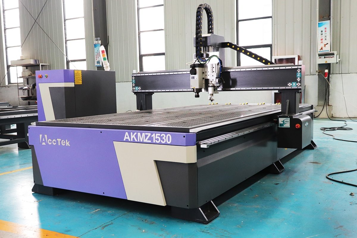
How To Program CNC Routers?
Programming CNC routers is the process of turning a design idea into precise machine movements. Whether the goal is cutting wood panels, engraving acrylic signs, machining aluminum parts, or producing custom furniture components, the CNC router can only perform accurately when it receives clear, well-prepared instructions. These instructions are usually created through a combination of CAD design, CAM toolpath generation, and G-code output, allowing the machine to understand where to move, how deep to cut, what speed to use, and which tool to operate.
For beginners, CNC router programming may sound complicated, but the workflow is easier to understand when broken into steps. First, the part or pattern is designed in CAD software. Then, CAM software is used to define cutting paths, tool selection, feed rate, spindle speed, cutting depth, and machining order. Finally, the generated program is transferred to the CNC router controller, where the operator checks the setup, secures the material, sets the machine origin, and starts the cutting process.
Well-programmed CNC routers do more than simply follow lines. It helps improve cutting accuracy, reduce material waste, protect cutting tools, shorten production time, and prevent common machining problems such as burning, rough edges, tool breakage, vibration, and dimensional errors. Poor programming, on the other hand, can lead to inaccurate parts, damaged materials, unsafe operation, or even machine failure.
This article explains how to program CNC routers in a practical and easy-to-follow way. It covers the basic programming workflow, commonly used software, important cutting parameters, toolpath strategies, G-code fundamentals, setup procedures, testing methods, and programming tips for different materials. By understanding these key steps, operators can create safer, more efficient, and more reliable CNC routing programs for both small workshops and industrial production environments.
Table of Contents
Understanding CNC Router Programming
CNC router programming is the foundation of every successful routing operation. Before CNC routers can cut, carve, drill, engrave, or shape a material, it needs a clear set of instructions that tell the machine exactly what to do. These instructions control the movement of the cutting tool, the depth of cut, spindle speed, feed rate, cutting sequence, tool changes, and machining path. Without proper programming, even high-quality CNC routers cannot produce accurate, clean, or repeatable results.
In most CNC routing applications, programming connects the design stage with the actual machining process. A product may begin as a drawing, CAD model, customer file, or simple sketch, but it must be converted into machine-readable commands before production can begin. This conversion process may be done manually by writing G-code or automatically through CAM software. The goal is always the same: to create a safe, efficient, and accurate toolpath that allows the CNC router to produce the required part according to the design.
Understanding CNC router programming helps operators make better decisions during setup and production. It allows them to choose the correct tools, avoid machining errors, improve surface finish, reduce material waste, and extend tool life. For beginners, programming may seem technical at first, but once the basic concepts are understood, the process becomes much easier to manage.
What CNC Router Programming Means
CNC router programming means creating the instructions that guide the CNC router during machining. These instructions tell the machine where to move, how fast to move, how deep to cut, when to turn the spindle on or off, and how to follow the required cutting path. The program acts like a detailed roadmap for the machine, converting a digital design into physical movement.
The most common programming language used by CNC routers is G-code. G-code includes commands that control machine motion, such as straight-line movements, arc movements, positioning, tool lifting, and cutting depth. For example, one command may move the tool to a specific coordinate, while another command may lower the tool into the material. Additional commands may control spindle speed, feed rate, tool compensation, or program stops.
However, CNC router programming is not just about writing code. It also involves planning the machining strategy. The programmer must consider the material type, material thickness, tool diameter, cutting direction, step-down depth, feed rate, spindle speed, holding method, and required finish quality. A program for cutting plywood is different from a program for routing aluminum, acrylic, MDF, foam, or solid wood. Each material has different cutting behavior, chip formation, heat sensitivity, and tool requirements.
Good CNC router programming also includes setting the correct machine origin and work coordinate system. The machine needs to know where the material is placed and where the cutting job should begin. This is usually done by setting the X, Y, and Z zero points. If the origin is wrong, the machine may cut in the wrong location, cut too deep, or damage the material and tooling.
In simple terms, CNC router programming is the process of turning design intent into controlled machine action. It combines design knowledge, machining knowledge, software operation, and practical workshop experience.
Manual Programming and CAM Programming
There are two main ways to program CNC routers: manual programming and CAM programming. Both methods can produce usable programs, but they are suited to different situations.
Manual programming means writing or editing G-code directly. The programmer creates the machine commands line by line, controlling movement, cutting depth, feed rate, spindle speed, and machining sequence without relying heavily on automatic toolpath software. Manual programming is useful for simple operations such as drilling holes, cutting straight lines, making basic profiles, surfacing a workpiece, or testing machine movement.
One advantage of manual programming is that it helps operators understand how the CNC router actually works. By reading and writing G-code, operators can better understand coordinates, tool movements, feed rates, safe heights, and machine logic. This knowledge is also helpful when troubleshooting CAM-generated programs. If a toolpath does not behave as expected, an operator who understands G-code can often identify the problem more quickly.
However, manual programming has limitations. It becomes time-consuming and difficult when the part shape is complex. Curved profiles, 3D relief carving, nested sheet cutting, pocketing, engraving, and multi-tool operations are not practical to write manually in most cases. A small mistake in manual code can also cause serious machining errors, especially if the tool moves too deep, too fast, or in the wrong direction.
CAM programming is the more common method used in modern CNC routing. CAM software takes a CAD drawing or 3D model and converts it into toolpaths automatically. The programmer selects the tool, cutting depth, feed rate, spindle speed, machining operation, and cutting strategy. The CAM software then calculates the tool movement and generates the G-code through a post-processor that matches the specific CNC router controller.
CAM programming is especially useful for complex shapes, repeated production, 3D carving, cabinet manufacturing, sign making, furniture production, mold making, and nested sheet cutting. It saves time, reduces manual coding work, and allows the programmer to preview the toolpath before machining. Many CAM programs also include simulation functions, which help identify possible collisions, wrong cutting depths, or inefficient tool movements before the machine starts cutting.
Even when CAM software is used, operators should still understand the basics of CNC programming. CAM software can generate code, but it cannot always understand the real cutting conditions in the workshop. The operator still needs to check whether the selected tool is suitable, whether the feed rate is reasonable, whether the workpiece is secured properly, and whether the cutting sequence is safe. In practice, the best results often come from combining CAM efficiency with human machining experience.
Why Good Programming Matters
Good CNC router programming directly affects machining quality, productivity, safety, and cost. A well-written program allows the CNC router to cut accurately, maintain stable tool movement, reduce unnecessary travel, and produce consistent results. A poorly prepared program can cause rough edges, dimensional errors, tool marks, burning, vibration, tool breakage, material waste, and even machine damage.
Accuracy is one of the most important reasons programming matters. CNC routers are capable of repeatable precision, but that precision depends on correct toolpaths, cutting parameters, and setup instructions. If the tool diameter is entered incorrectly, the final part size may be wrong. If the cutting depth is too aggressive, the tool may deflect and produce inaccurate edges. If the toolpath strategy is poor, corners, holes, and pockets may not meet the required dimensions.
Programming also affects surface quality. The right feed rate, spindle speed, cutting direction, and step-over can produce smooth edges and clean surfaces. The wrong settings may cause burning in wood, melting in plastics, burrs in aluminum, or chipping in laminated materials. For visible products such as signs, furniture, decorative panels, and acrylic displays, programming quality can strongly influence the final appearance.
Efficiency is another key factor. A good program reduces unnecessary movements, arranges cutting operations logically, and selects toolpaths that shorten machining time. In production environments, even small time savings per part can become significant over hundreds or thousands of parts. Good programming also helps reduce tool changes, improve nesting efficiency, and maximize material usage.
Safety is equally important. CNC routers are powerful machines with a high-speed spindle and sharp cutting tools. Incorrect programming may cause the tool to plunge into clamps, cut outside the material area, move too fast, or crash into the worktable. Good programming includes safe heights, correct starting points, proper cutting order, and toolpath verification before machining begins.
Finally, good programming helps reduce operating costs. It lowers the risk of scrap parts, broken tools, machine downtime, and rework. It also makes production more predictable, which is especially important for workshops handling customer orders, batch production, or high-value materials.
Understanding CNC router programming is essential for anyone who wants to operate CNC routers safely and effectively. Programming is not only the act of creating machine code; it is the complete process of planning how a design will be machined. It includes choosing tools, setting cutting parameters, defining toolpaths, preparing G-code, checking machine coordinates, and verifying that the program matches the material and production goal.
Manual programming gives operators direct control over G-code and is useful for simple tasks, testing, and learning how CNC machines think. CAM programming, on the other hand, is faster and more practical for complex designs, 3D shapes, production work, and repeated jobs. In modern CNC routing, CAM software is widely used, but a basic understanding of manual programming remains valuable because it helps operators read, check, and troubleshoot machine instructions.
Good programming matters because it affects every part of the routing process. It improves accuracy, surface finish, efficiency, tool life, material usage, and operator safety. Well-programmed CNC routers can produce clean, consistent, and repeatable results, while poor programming can lead to wasted materials, damaged tools, unsafe operation, and poor product quality. For this reason, CNC router programming should be treated as a critical skill rather than a simple software step.
Basic CNC Router Concepts Before Programming
Before programming CNC routers, operators need to understand several basic machine concepts. CNC router programming is not only about creating G-code or using CAM software. It also requires a clear understanding of how the machine moves, how the workpiece is positioned, how toolpaths are created, and how cutting tools affect the final result. These basic concepts form the foundation for accurate, safe, and efficient CNC routing.
CNC routers follow programmed instructions based on coordinates, axes, cutting paths, and tool settings. If the programmer does not understand these elements, even a simple job can produce errors. The machine may cut in the wrong position, move in the wrong direction, cut too deeply, damage the material, or break the cutting tool. On the other hand, when these concepts are understood properly, the programming process becomes much easier to control.
For beginners, the most important concepts include machine axes, workpiece coordinates, toolpaths, and cutting tools. These elements are closely connected. The machine axes define how the router moves. The workpiece coordinates define where the cutting job starts. The toolpath defines the route the cutting tool follows. The cutting tool determines how the material is removed. Together, they decide whether the CNC router can produce the required part accurately and consistently.
Machine Axes
Machine axes describe the directions in which CNC routers can move. Most standard CNC routers use three main axes: X, Y, and Z. The X-axis usually represents left and right movement, the Y-axis usually represents front and back movement, and the Z-axis represents up and down movement. These three axes allow the cutting tool to move across the worktable and cut the material at different depths.
In typical CNC routers, the X and Y axes control the horizontal position of the tool, while the Z-axis controls cutting depth. For example, when cutting a rectangular panel, the router moves along the X and Y axes to follow the shape of the rectangle. When the tool needs to enter or exit the material, the Z-axis moves the tool downward or upward. If any axis is set incorrectly, the tool may cut in the wrong location or at the wrong depth.
Some CNC routers also include additional axes, such as a rotary axis or a fourth axis. A rotary axis allows cylindrical materials to rotate while the cutting tool works on the surface. This is useful for engraving round columns, chair legs, table legs, decorative posts, and other curved objects. More advanced CNC machines may include five-axis movement, but most woodworking, sign-making, cabinet-making, and general routing applications use three-axis or four-axis machines.
Understanding machine axes is important because programming is based on movement. Every command tells the machine where to move along one or more axes. The operator must know the machine’s direction, travel range, safe height, and movement limits before running a program. This helps prevent overtravel errors, collisions, and incorrect cutting positions.
Workpiece Coordinates
Workpiece coordinates define the position of the material and the starting point of the machining job. CNC routers has its own machine coordinate system, but the operator usually creates a separate work coordinate system for each job. This work coordinate system tells the machine where the material is located on the table and where the program should begin cutting.
The most important point in the workpiece coordinate system is the work origin, also called the zero point. This is usually set at a corner, the center, or the top surface of the material. For many sheet-cutting jobs, the origin is set at the front-left or front-right corner of the workpiece. For engraving or symmetrical parts, the origin may be set at the center. The Z-zero point is often set on the top surface of the material, but in some cases, it may be set on the machine table or spoilboard.
Correct coordinate setup is critical. If the X and Y zero points are wrong, the router may cut outside the material or damage clamps and fixtures. If the Z-zero point is wrong, the tool may cut too shallow, too deep, or directly into the worktable. This is one of the most common beginner mistakes in CNC routing.
Workpiece coordinates also affect repeatability. In production work, operators may need to cut the same part many times. A consistent coordinate setup allows the same program to be used repeatedly with predictable results. For this reason, many workshops use positioning pins, vacuum tables, fixtures, stops, or jigs to keep the material in the same location for each job.
Before running the CNC router program, the operator should always confirm the work origin, material size, material thickness, and safe cutting area. These checks help ensure that the digital program matches the physical setup on the machine.
Toolpaths
A toolpath is the route that the cutting tool follows during machining. It tells the CNC router how to move through the material to create the desired shape, pocket, hole, engraving, or surface. Toolpaths are usually created in CAM software, where the programmer selects the machining operation and defines the cutting strategy.
There are several common types of toolpaths used in CNC routing. Profile toolpaths are used to cut along the outside or inside edge of a shape. Pocket toolpaths remove material from an enclosed area. Drilling toolpaths create holes at specific positions. Engraving toolpaths follow lines, letters, or decorative patterns. 3D toolpaths are used for relief carving, molds, curved surfaces, and complex shapes.
Toolpath direction is also important. In CNC routing, the tool may cut using conventional cutting or climb cutting. Conventional cutting moves the tool against the direction of cutter rotation, while climb cutting moves with the cutter rotation. Each method has advantages depending on the material, tool, machine rigidity, and desired edge quality. For example, climb cutting may produce a cleaner edge in some materials, but it can also pull the tool more aggressively if the setup is not stable.
Depth control is another key part of toolpath planning. Instead of cutting through thick material in one pass, the programmer often divides the cut into multiple passes. This is called step-down. Proper step-down reduces tool load, heat, vibration, and the risk of tool breakage. Step-over is also important, especially in pocketing and 3D machining. It controls how much the tool overlaps each pass, affecting surface finish and machining time.
A good toolpath should be accurate, efficient, and safe. It should remove material in a logical order, avoid unnecessary travel, protect the tool, keep the workpiece secure, and reduce the chance of collision. Before machining, the toolpath should be previewed or simulated whenever possible. This helps the operator find possible errors before the program is sent to the CNC router.
Cutting Tools
Cutting tools are one of the most important factors in CNC router programming. The tool determines how the material is removed, what edge quality can be achieved, how fast the machine can cut, and how much load is placed on the spindle and machine structure. Choosing the wrong tool can cause poor surface finish, burning, melting, chipping, vibration, or tool breakage.
CNC routers use many types of cutting tools, including straight bits, spiral bits, compression bits, V-bits, ball nose bits, engraving bits, surfacing bits, and drilling bits. Straight bits are often used for general cutting and grooving. Spiral bits are common for cleaner chip removal and smoother cutting. Compression bits are useful for cutting laminated boards because they reduce chipping on both the top and bottom surfaces. V-bits are used for engraving, lettering, and decorative carving. Ball nose bits are commonly used for 3D carving and curved surfaces.
Tool size also matters. A larger diameter tool can remove material faster and is usually stronger, but it cannot create small details or sharp internal corners. A smaller diameter tool can produce fine details, but it is more fragile and may require slower cutting speeds. The flute design, cutting length, shank diameter, coating, and material of the tool should also match the job requirements.
Different materials require different tools and cutting parameters. Wood, MDF, plywood, acrylic, aluminum, foam, and composite materials behave differently during cutting. For example, acrylic may melt if the spindle speed is too high or chip evacuation is poor. Aluminum requires proper chip removal, suitable feed rates, and often a more rigid setup. MDF produces fine dust and can wear tools quickly. Solid wood may chip or burn depending on grain direction, tool sharpness, and feed speed.
In programming, the selected cutting tool must match the toolpath settings. The tool diameter must be entered correctly in CAM software. The cutting depth, feed rate, spindle speed, plunge rate, and step-over should be suitable for the tool and material. Even a small mistake in tool data can change the final part size or cause machining failure.
Understanding basic CNC router concepts before programming helps operators avoid many common mistakes. Machine axes define how the CNC router moves, while workpiece coordinates tell the machine where the material is located and where cutting should begin. Toolpaths determine how the cutting tool moves through the material, and cutting tools determine how effectively the material is removed.
These concepts are connected in every CNC routing job. A correct toolpath will not produce good results if the work origin is wrong. A suitable coordinate setup will not prevent failure if the wrong cutting tool is used. A powerful machine will still produce poor parts if the cutting parameters are not matched to the tool and material. For this reason, CNC router programming should always begin with a clear understanding of machine movement, material position, toolpath strategy, and tool selection.
By mastering these fundamentals, beginners can program CNC routers with more confidence. They can reduce setup errors, improve cutting accuracy, extend tool life, protect materials, and create safer machining programs. These basic concepts also make it easier to understand more advanced topics such as CAD/CAM workflow, G-code commands, cutting parameters, nesting, tool compensation, and multi-axis routing.
The Complete CNC Router Programming Workflow
Programming CNC routers is a step-by-step process that connects design, machining strategy, software preparation, machine setup, and final production. CNC routers do not automatically know how to cut a part simply because a drawing exists. The design must be converted into toolpaths, the toolpaths must be converted into machine-readable code, and the machine must be set up correctly before cutting begins. Each stage affects the final result, so skipping or rushing any step can lead to inaccurate parts, poor edge quality, broken tools, wasted material, or unsafe operation.
Complete CNC router programming workflows usually start with understanding the job requirements. The programmer must know what material will be cut, what shape or product must be produced, what tolerance is required, what surface finish is expected, and whether the job is a one-off project or a repeated production task. After that, the design is created or imported into CAD/CAM software, the material size is defined, cutting tools are selected, and toolpaths are generated.
Once the toolpaths are created, they should be simulated to check for errors before the program is sent to the CNC router. The toolpaths are then post-processed into G-code that matches the machine controller. After that, the operator sets up the material, tools, machine origin, clamps or vacuum hold-down, and safety checks. Before full production, a test run helps confirm that the program is correct. Finally, the program is adjusted, saved, and documented for future use.
This workflow helps operators move from design to finished part in a controlled and repeatable way. It is useful for woodworking, sign making, cabinet production, acrylic cutting, aluminum machining, furniture manufacturing, foam cutting, mold making, and many other CNC router applications.
Step 1: Define the Job Requirements
The first step in CNC router programming is to define exactly what the job requires. Before opening CAD or CAM software, the programmer should understand the purpose of the part, the material being used, the required dimensions, the acceptable tolerance, the cutting quality expected, and the quantity to be produced. Clear job requirements help prevent mistakes later in the workflow.
The material type is one of the most important details. Wood, plywood, MDF, acrylic, aluminum, foam, plastic, and composite materials all require different cutting strategies. A program designed for MDF may not work well for aluminum. A toolpath suitable for acrylic may create burning or melting if the feed rate, spindle speed, or chip evacuation is wrong. Understanding the material from the beginning allows the programmer to choose suitable tools, speeds, depths, and cutting methods.
The programmer should also confirm the material thickness and sheet size. Even small differences in thickness can affect cutting depth, engraving depth, pocket depth, and through-cut settings. If the actual material is thinner or thicker than the value entered in the software, the tool may fail to cut through, cut too deeply into the spoilboard, or produce inaccurate features.
Another important requirement is the final part quality. Some jobs only require rough cutting, while others need clean edges, tight tolerances, smooth surfaces, or decorative details. A cabinet panel may require accurate dimensions and clean edges. A 3D relief carving may require a smooth surface finish. An aluminum part may require careful chip control and dimensional accuracy. The required result determines the toolpath type, cutting parameters, and finishing strategy.
Production quantity should also be considered. A one-time prototype may be programmed differently from a repeated production job. For mass production, the programmer may focus on reducing cycle time, improving nesting efficiency, and making the program easy to repeat. For custom work, flexibility and accuracy may matter more than speed.
Step 2: Create or Import the Design
After the job requirements are clear, the next step is to create or import the design. The design may be created directly in CAD software, drawing software, or integrated CAD/CAM software. It may also be imported from customer files, engineering drawings, vector graphics, 3D models, or scanned artwork.
For 2D cutting, common file types include DXF, DWG, SVG, EPS, AI, and PDF, depending on the software being used. These files are often used for profile cutting, engraving, drilling, pocketing, sign making, cabinet parts, and sheet nesting. For 3D machining, common file types may include STL, STEP, IGES, OBJ, or other 3D model formats. These are used for relief carving, molds, curved surfaces, prototypes, and complex-shaped parts.
Before creating toolpaths, the design must be checked carefully. The programmer should look for open vectors, duplicate lines, overlapping geometry, incorrect dimensions, broken curves, unnecessary nodes, and disconnected shapes. These design problems can cause CAM software to generate incorrect or incomplete toolpaths. For example, an open vector may prevent a profile cut from closing properly, while duplicate lines may cause the tool to cut the same area twice.
The design should also be scaled correctly. Imported files sometimes appear in the wrong unit system, such as inches instead of millimeters or millimeters instead of inches. If the scale is wrong, the final part will be the wrong size. The programmer should measure key dimensions inside the software before moving forward.
For production jobs, the design may also need layout planning. Multiple parts may be arranged on one sheet to reduce material waste. This process is called nesting. Good nesting can improve material utilization and reduce production cost, especially when cutting plywood, MDF, acrylic sheets, aluminum plates, or plastic panels.
Step 3: Set the Material and Job Size
Once the design is ready, the programmer must set the material size and job setup in the CAM software. This step tells the software the physical dimensions of the workpiece and where the design is located on the material. It also defines the coordinate system used for machining.
The material length, width, and thickness should match the actual workpiece. If the software setup does not match the real material, the toolpath may be placed incorrectly or cut outside the usable area. For sheet materials, the programmer should also leave enough margin around the edges for clamps, screws, vacuum zones, or hold-down fixtures.
The work’s origin must also be selected. The origin is the zero point used by the CNC router to locate the job. It may be set at a corner of the material, the center of the material, the top surface, or the machine bed, depending on the application. For most sheet-cutting jobs, the X and Y origin is often placed at one corner of the material. For engraving, round parts, or symmetrical designs, the center point may be more convenient.
The Z-zero position is especially important. If Z-zero is set on the top of the material, the machine uses the material surface as the reference for cutting depth. If Z-zero is set on the machine bed or spoilboard, the machine uses the bottom of the material as the reference. Both methods can work, but the CAM setup and machine setup must match. If the software assumes Z-zero is on top of the material, but the operator sets it on the spoilboard, the tool may cut at the wrong depth.
At this stage, the programmer should also define safe clearance heights. The clearance height is the height at which the tool moves above the material when traveling between cuts. It must be high enough to avoid clamps, screws, fixtures, and uneven material, but not so high that it wastes unnecessary movement time.
Step 4: Choose the Cutting Tools
Choosing the correct cutting tools is one of the most important parts of CNC router programming. The tool determines how the machine removes material, how clean the edge will be, how fast the job can run, and how much load is placed on the spindle. A good tool choice improves accuracy, surface finish, tool life, and machining efficiency.
Different tools are used for different operations. End mills are commonly used for cutting profiles, pockets, slots, and general machining. Spiral bits provide better chip removal and smoother cutting than many straight bits. Compression bits are often used for plywood, laminated boards, and veneered panels because they help reduce chipping on both the top and bottom surfaces. V-bits are used for engraving, lettering, chamfering, and decorative carving. Ball nose bits are used for 3D carving, relief work, molds, and curved surfaces. Surfacing bits are used to flatten spoilboards or level large surfaces.
The tool diameter must match the design requirements. A large-diameter tool is stronger and can remove material faster, but it cannot cut small details or sharp internal corners. A small-diameter tool can create fine details, but it is more fragile and usually requires slower feed rates and shallower cuts. If the design includes small holes, narrow grooves, or detailed engraving, the selected tool must be small enough to fit those features.
Tool flute type and cutting direction also matter. Up-cut bits pull chips upward and are useful for chip evacuation, but they may cause chipping on the top surface of some materials. Down-cut bits push chips downward and can create a cleaner top edge, but chip evacuation may be more difficult. Compression bits combine up-cut and down-cut geometry, making them suitable for clean through-cuts in laminated sheet materials.
The programmer must enter accurate tool information into the CAM software. Tool diameter, cutting length, flute length, step-down, step-over, feed rate, plunge rate, and spindle speed should be set correctly. Incorrect tool data can cause wrong part dimensions, poor cutting quality, tool breakage, or machine overload.
Step 5: Create Toolpaths
After the material and tools are defined, the programmer creates toolpaths. A toolpath is the route the cutting tool follows to machine the design. This is where the design becomes a practical cutting strategy.
The type of toolpath depends on the required operation. A profile toolpath cuts along the inside or outside of a vector to create the final shape of a part. A pocket toolpath removes material from an enclosed area. A drilling toolpath creates holes at defined positions. An engraving toolpath follows lines, letters, logos, or decorative patterns. A V-carving toolpath uses a V-bit to create carved text or decorative details. A 3D roughing toolpath removes bulk material from a 3D model, while a 3D finishing toolpath creates the final smooth surface.
The programmer must decide whether the tool cuts on the outside, inside, or directly on the line. For example, when cutting the outer profile of a part, the tool usually cuts outside the design line so the final part size remains correct. When cutting a hole, the tool usually cuts inside the line so the hole size is correct. If this setting is wrong, the part may become too large, too small, or unusable.
Cutting depth must also be planned. Instead of cutting through thick material in one pass, the programmer usually divides the cut into multiple passes. This reduces cutting load, protects the tool, and improves machining stability. The correct step-down depends on the material, tool diameter, spindle power, machine rigidity, and desired finish.
Tabs, bridges, or onion-skin cutting may be added to hold parts in place during cutting. When a part is almost cut free, it can move, vibrate, or be pulled into the tool. Tabs leave small uncut sections that keep the part attached to the sheet until the job is finished. Onion-skin cutting leaves a thin layer of material at the bottom, which can be removed later. These methods are especially useful for small parts, thin materials, and nested sheet cutting.
Toolpath order should be planned logically. Internal cuts, holes, pockets, and engraving are usually completed before the outer profile is cut. This keeps the workpiece stable for as long as possible. If the outside profile is cut first, the part may shift before internal features are finished.
Step 6: Simulate the Program
Before sending the program to the CNC router, the toolpaths should be simulated in the CAM software. Simulation allows the programmer to see how the tool will move, how material will be removed, and whether the final part matches the design. It is one of the best ways to find mistakes before they happen on the machine.
During simulation, the programmer should check the cutting order, tool movement, cutting depth, tool changes, entry and exit points, and final part shape. The simulation should show whether the tool cuts on the correct side of the line, whether pockets are cleared properly, whether holes are placed correctly, and whether the finished part has the correct dimensions.
Simulation can also reveal dangerous problems. The tool may plunge too deeply, move through clamps, cut outside the material, start in the wrong location, or travel at an unsafe height. In 3D machining, simulation can show whether the tool reaches all required surfaces or leaves uncut material. In nested cutting, it can show whether parts are too close together or whether the toolpath creates weak areas in the sheet.
Although simulation is useful, it does not replace real machine judgment. Software may not know the exact clamp height, material warping, tool wear, vacuum strength, or machine condition. The operator should still inspect the physical setup before cutting. However, simulation greatly reduces the risk of programming errors and helps improve confidence before machining begins.
For important jobs, expensive materials, or complex 3D parts, simulation should be treated as a required step, not an optional one.
Step 7: Post-Process the Toolpaths
After the toolpaths are checked and approved, they must be post-processed. Post-processing converts the toolpaths from the CAM software into G-code or another machine-readable format that the CNC router controller can understand.
Different CNC routers use different controllers, and each controller may require a specific code format. A program for one controller may not run correctly on another controller if the post-processor is wrong. Common controller systems may use different command formats, file extensions, coordinate behavior, tool-change commands, spindle commands, or arc movement settings. That is why choosing the correct post-processor is critical.
The post-processor translates the toolpath into commands for machine movement, spindle control, feed rate, plunge rate, tool changes, safe heights, and program start and end behavior. It may also include commands for coolant, dust collection, vacuum zones, automatic tool changers, or special machine functions if the CNC router supports them.
After post-processing, the programmer should save the output file with a clear and organized name. The file name should help identify the project, material, tool, version, and date. This is especially important in workshops where many similar programs are used. Poor file naming can lead to running the wrong program, which may damage material or create incorrect parts.
The generated code should also be reviewed when possible. Even if the operator does not read every line, it is useful to check the beginning and end of the program, confirm the units, verify safe Z movements, check spindle start commands, and make sure the program uses the expected work coordinate system.
Step 8: Set Up the CNC Router
Once the program is ready, the CNC router must be prepared for machining. Machine setup is just as important as software programming because the program will only work correctly if the physical setup matches the digital setup.
First, the operator should place the material on the machine table and secure it properly. Depending on the machine and application, this may be done with clamps, screws, vacuum hold-down, double-sided tape, jigs, fixtures, or positioning stops. The material must not move during cutting. Even a small movement can ruin the part, break the tool, or damage the machine.
Next, the correct cutting tool must be installed in the spindle or tool holder. The tool should be clean, sharp, properly tightened, and suitable for the material. If the machine has an automatic tool changer, the tool numbers in the machine must match the tool numbers in the program. If the wrong tool is loaded, the cutting depth, width, and final dimensions may be incorrect.
The operator must then set the work origin. This includes setting X-zero, Y-zero, and Z-zero according to the CAM setup. If the CAM software used the front-left corner as the origin, the machine should be zeroed at that same location. If the software uses the material surface for Z-zero, the machine should also use the material surface. The digital setup and physical setup must match exactly.
Before cutting, the operator should check the toolpath area for clamps, screws, fixtures, and other obstacles. The dust collection system, air assist, vacuum pump, cooling system, and spindle should also be checked if they are part of the process. Safety covers, emergency stop buttons, and machine limits should be confirmed before starting the job.
Step 9: Run a Test
Before running the final cut, it is best to perform a test. Testing helps confirm that the program, tool, material setup, and machine coordinates are correct. This is especially important for new programs, expensive materials, unfamiliar tools, complex designs, or first-time production jobs.
One common method is an air cut. In an air cut, the machine runs the program above the material without actually cutting. This allows the operator to observe the tool movement and confirm that the machine follows the expected path. The operator can check whether the job starts in the correct location, whether the tool stays within the material area, whether travel movements are safe, and whether the cutting sequence makes sense.
Another method is to run the program on scrap material. This is useful when testing cutting quality, depth, feed rate, spindle speed, and toolpath strategy. Scrap testing helps reveal problems such as burning, chipping, melting, rough edges, vibration, poor chip evacuation, or incorrect dimensions. It is much better to discover these issues on scrap material than on the final workpiece.
The operator can also run the first pass slowly, using feed override controls if the CNC controller supports them. Reducing the feed rate during the first cut gives the operator more time to observe the machine and stop the job if something looks wrong.
During testing, the operator should listen to the cutting sound, watch chip formation, check tool vibration, monitor spindle load if available, and inspect the first cuts. A smooth cutting sound and proper chip formation usually indicate that the tool and parameters are suitable. Burning, smoke, squealing, dust instead of chips, heavy vibration, or tool deflection may indicate that adjustments are needed.
Step 10: Adjust and Save the Final Program
After testing, the programmer should adjust the program if needed. CNC router programming is often an iterative process. The first version of a program may work, but small improvements can make it safer, faster, cleaner, or more repeatable.
Common adjustments include changing the feed rate, spindle speed, cutting depth, step-down, step-over, ramp entry, tab size, toolpath order, lead-in and lead-out settings, or clearance height. If the cut edge is rough, the programmer may need to adjust feed speed, tool type, cutting direction, or finishing passes. If the tool is overheating, the feed rate, spindle speed, or chip evacuation may need improvement. If parts move during cutting, more tabs, better hold-down, or a different cutting sequence may be needed.
Dimensional accuracy should also be checked. After a test cut, the operator should measure important features such as length, width, hole diameter, pocket depth, and edge quality. If the dimensions are incorrect, the cause may be tool diameter settings, machine calibration, tool deflection, material movement, or incorrect compensation.
Once the program is confirmed, it should be saved properly. The final version should be clearly named and stored in an organized folder. It is useful to keep notes about the material, tool type, tool diameter, feed rate, spindle speed, step-down, work origin, hold-down method, and any special setup instructions. These notes make it easier to repeat the job in the future.
For production environments, the final program may become part of a standard process. Operators can reuse it for repeat orders, training, quality control, and future improvements. Good documentation reduces mistakes and helps maintain consistent production quality.
The complete CNC router programming workflow begins with understanding the job and ends with saving a proven, reliable program. Each step has a specific purpose. Defining the job requirements helps the programmer understand the material, dimensions, tolerance, quality expectations, and production goals. Creating or importing the design converts the idea into digital geometry. Setting the material and job size ensures that the software setup matches the physical workpiece. Choosing the right cutting tools allows the machine to remove material efficiently and safely.
Creating toolpaths is the core of CNC router programming because it determines how the machine will cut the design. Simulation helps identify programming errors before machining begins, while post-processing converts the toolpaths into code that the CNC router controller can understand. Machine setup then connects the digital program to the real workpiece through proper material holding, tool installation, and coordinate setting.
Running a test is an important safety and quality step. It allows the operator to confirm the tool movement, cutting depth, cutting quality, and machine behavior before full production. After testing, the program should be adjusted and saved as the final version, along with clear notes for future use.
By following this workflow, operators can reduce errors, improve cutting accuracy, protect tools and materials, and create repeatable CNC routing programs. A structured workflow also makes programming easier for beginners and more efficient for experienced users. Whether producing a single custom part or running batch production, a complete programming process is the key to safe, accurate, and efficient CNC router operation.
CAD Preparation for CNC Router Programming
CAD preparation is one of the most important steps before CNC router programming. CNC routers do not understand design intent in the same way a person does. It follows the geometry, dimensions, and toolpaths created from the digital file. If the CAD file contains errors, unclear shapes, incorrect scale, open vectors, overlapping lines, or poorly prepared text, those problems can carry into CAM software and eventually appear during machining.
Good CAD preparation helps the CAM software generate accurate and efficient toolpaths. It also reduces programming time, prevents cutting mistakes, improves part quality, and lowers the risk of wasted material. Before creating toolpaths, the design should be checked carefully to make sure it is clean, correctly scaled, properly organized, and suitable for the selected cutting tools.
For CNC router work, CAD preparation is especially important because routing tools have physical size and cutting limitations. A router bit cannot cut infinitely sharp internal corners, extremely narrow grooves, or details smaller than its diameter. Text, logos, decorative patterns, holes, slots, and pockets must all be designed with the cutting tool in mind. A drawing may look perfect on a computer screen, but it may not be practical to machine unless it is prepared correctly.
Drawing Clean Geometry
Clean geometry means the CAD design is made of accurate, complete, and machine-ready lines, curves, arcs, and shapes. In CNC router programming, the CAM software uses these geometric elements to create toolpaths. If the geometry is messy, broken, duplicated, or incomplete, the toolpaths may fail or produce incorrect cutting results.
One common problem is open vectors. A shape that appears closed visually may actually have tiny gaps between endpoints. This can prevent the CAM software from creating a proper profile, pocket, or engraving toolpath. For example, if a rectangle has one corner that is not fully connected, the software may not recognize it as a closed shape. The result may be an incomplete cut, a failed pocket operation, or an unexpected tool movement.
Duplicate lines are another common issue. Sometimes, imported files contain two or more lines stacked on top of each other. This may happen when designs are exported from drawing software, converted from PDFs, or copied from other files. Duplicate geometry can cause the CNC router to cut the same path multiple times, increasing machining time and possibly burning the material, wearing the tool, or damaging the edge quality.
Overlapping vectors, self-intersecting curves, unnecessary nodes, and broken arcs should also be removed. These issues can confuse CAM software and create strange toolpath behavior. A simple design with clean geometry is usually more reliable than a visually complex file filled with unnecessary points and poorly connected curves.
Before moving to CAM programming, the designer should inspect the CAD file carefully. Closed shapes should be joined properly, extra lines should be deleted, curves should be simplified where possible, and important features should be organized logically. Layers can also be useful. For example, one layer may contain cutting profiles, another may contain engraving lines, and another may contain drilling points. This makes toolpath creation easier and reduces the chance of selecting the wrong geometry.
Clean geometry is not only about avoiding errors. It also helps improve cutting efficiency. Smooth curves, logical shapes, and well-organized features allow the CNC router to move more naturally, reduce unnecessary stops, and produce better surface quality.
Confirming Units and Scale
Confirming units and scale is essential before creating CNC router programs. A file that looks correct on the screen may still be the wrong size if it was created or imported using different units. This is especially common when designs are shared between different software programs, different countries, or different production teams.
The most common unit issue is the difference between millimeters and inches. If a design created in inches is imported as millimeters, the part may become much smaller than intended. If a design created in millimeters is imported as inches, the part may become much larger. Either mistake can lead to unusable parts, wasted material, and possible machine travel problems.
Before programming, the operator should check the overall size of the design and measure several key dimensions. Important dimensions may include the total length, width, hole diameter, slot width, pocket depth, spacing between holes, and distance from edges. These measurements should match the job drawing, customer requirement, or production specification.
Scale should also be checked when working with logos, artwork, scanned images, or converted PDF files. These files may not always import at the correct size. A logo may need to be resized to fit a sign panel. A decorative pattern may need to be scaled to match a furniture part. A template may need to be adjusted to match actual hardware or assembly requirements.
It is also important to consider material size when confirming scale. The design should fit within the usable cutting area of the material, not just within the machine table size. Space must be allowed for clamps, vacuum zones, screws, tabs, edge margins, and tool clearance. A design that fits the sheet exactly on screen may be risky in real production if there is no allowance for positioning error or hold-down space.
For repeated production, scaling should be controlled carefully. Once the correct size is confirmed, the file should be saved as a master version. This helps prevent accidental resizing in future jobs. Clear file naming and version control can also help operators avoid using outdated or incorrectly scaled designs.
Preparing Text and Logos
Text and logos require special attention in CNC router programming because they often contain complex curves, small details, thin strokes, and decorative shapes. A logo that looks clear in graphic design software may not be ready for routing. Before machining, text and logos must be converted into clean vector geometry and adjusted according to the tool size, cutting method, and material.
For text, the first step is usually converting fonts into outlines or curves. If the text remains editable as a font, the CAM software or another computer may not recognize it correctly, especially if the font is missing. Converting text to vectors makes the shape fixed and ensures that the letters appear exactly as intended. After conversion, the outlines should be checked for open curves, overlapping paths, and unnecessary nodes.
Small text can be difficult to machine with CNC routers. Unlike a laser or printer, a router uses a physical cutting tool with a defined diameter. If the letters are too small or the strokes are too narrow, the bit may not be able to cut them clearly. Thin strokes may disappear, corners may become rounded, and small spaces inside letters may be lost. For this reason, the designer should choose text size, font style, and letter spacing based on the cutting tool and material.
Logos also need to be cleaned before toolpath creation. Many logo files contain decorative details, gradients, shadows, outlines, or overlapping shapes that are useful for printing but not suitable for routing. These elements may need to be simplified. The final routing version should contain clear vector outlines that define what should be cut, engraved, pocketed, or carved.
For V-carving, text and logos should usually be closed vector shapes. The width of each stroke affects the depth and appearance of the carved result. For profile cutting, the tool must have enough space to move around the letters or logo shapes. For engraving, fine lines should be wide enough and deep enough to remain visible after machining.
The material also affects how text and logos should be prepared. Acrylic signs may need smooth curves and polished edges. Wood engraving may require larger details to avoid chipping along the grain. MDF allows fine detail but creates dust and may need finishing. Aluminum requires stronger toolpath planning and may not support extremely delicate details with a large router bit.
A well-prepared text or logo file should be simple, clean, scalable, and suitable for the chosen machining method. This helps the CNC router produce a clear and professional result instead of a rough or distorted design.
Designing for the Tool Diameter
Designing for the tool diameter is one of the most important principles in CNC router CAD preparation. Every router bit has a physical size, and that size limits what the machine can cut. CNC routers cannot cut a feature smaller than the diameter of the selected tool, and they cannot create perfectly sharp internal corners with a round bit.
For example, if a design includes a narrow slot that is 3 mm wide, a 6 mm tool cannot fit into that slot. If the programmer tries to create a toolpath anyway, the CAM software may reject the operation, skip the feature, or create an incorrect path. To machine that slot, the designer must either widen the slot or choose a smaller tool. This is why tool diameter should be considered during CAD design, not only during CAM programming.
Internal corners are another important issue. Because router bits are round, inside corners will naturally have a radius equal to the tool radius. If a part needs to fit into another component with square internal corners, the design may require relief cuts, dogbone corners, or T-bone corners. These small added cuts allow square-edged parts to fit together properly, especially in cabinet making, furniture assembly, joinery, and interlocking panel designs.
Tool diameter also affects spacing between parts. When nesting multiple parts on a sheet, there must be enough distance between shapes for the tool to pass through. If parts are too close together, the tool may cut into neighboring parts or leave weak material between them. The spacing should account for tool diameter, cutting tolerance, tabs, material movement, and edge quality.
Small details should be designed with the selected tool in mind. Fine lettering, decorative patterns, small holes, narrow grooves, and thin walls may look good in CAD but may be difficult or impossible to cut cleanly. A smaller tool can create more detail, but it is usually slower, weaker, and more likely to break. A larger tool is faster and stronger, but cannot machine fine features. Good design balances detail, tool strength, machining time, and final quality.
Designing for tool diameter also helps improve efficiency. If a part can be designed to use one or two standard tools instead of many specialized tools, the job becomes faster and easier to run. Fewer tool changes reduce setup time, programming complexity, and the risk of operator error.
In professional CNC router programming, CAD design and tool selection should be considered together. The best designs are not only visually correct; they are also practical to machine with available tools, realistic tolerances, and efficient toolpaths.
CAD preparation is a critical step in CNC router programming because the quality of the digital design directly affects the quality of the machining program. Clean geometry helps CAM software recognize shapes correctly and generate reliable toolpaths. Removing open vectors, duplicate lines, overlapping curves, and unnecessary nodes reduces the chance of toolpath errors and improves machining efficiency.
Confirming units and scale prevents one of the most common and costly programming mistakes. Before creating toolpaths, the operator should verify that the design uses the correct measurement system and matches the required part size. This is especially important when importing files from customers, graphic design software, scanned drawings, or different CAD systems.
Text and logos should be converted into clean vector geometry and adjusted for the routing process. Fonts, decorative artwork, thin lines, and small details must be prepared according to the tool, material, and machining method. A design suitable for printing may not be suitable for CNC routing without cleanup and simplification.
Designing for the tool diameter ensures that the part can actually be machined. Router bits have physical limits, so slots, holes, internal corners, spacing, and fine details must be designed with the selected tool in mind. By preparing CAD files properly before CAM programming, operators can reduce errors, save time, protect materials and tools, and create more accurate CNC router programs.
CAM Programming in Detail
CAM programming is the stage where a CAD design becomes a practical machining plan. While CAD defines the shape of the part, CAM defines how the CNC router will cut that shape. This includes selecting toolpath types, choosing cutting tools, setting cutting depth, defining step-down and step-over values, adding lead-in and lead-out moves, controlling plunge methods, and using tabs or bridges to keep parts stable during machining.
A good CAM program does more than create movement commands. It controls cutting load, machining time, edge quality, tool life, material stability, and operator safety. The same design can produce very different results depending on how the CAM settings are prepared. For example, a profile cut may produce a clean edge if the correct toolpath, feed rate, step-down, and cutting direction are used. The same cut may burn the material, break the tool, or leave rough edges if the settings are incorrect.
CAM programming is also where the operator balances speed and quality. A faster program may save time, but it can increase tool wear, vibration, or surface defects. A slower program may improve finish quality, but it may reduce productivity. The best CAM setup depends on the material, machine rigidity, spindle power, tool diameter, tool condition, hold-down method, and required final result.
For CNC router users, understanding CAM programming in detail is essential. It helps operators move beyond simply clicking automatic software options and allows them to create toolpaths that are accurate, efficient, and reliable.
Choosing the Right Toolpath Type
Choosing the right toolpath type is one of the first and most important decisions in CAM programming. Each toolpath type is designed for a specific machining purpose, and using the wrong one can lead to poor results or failed cuts.
A profile toolpath is used to cut along the edge of a shape. It may cut outside the line, inside the line, or directly on the line, depending on the part requirement. Outside profile cutting is commonly used when cutting out the external shape of a part. Inside profile cutting is used for holes, slots, and internal openings. Cutting directly on the line may be used for engraving, marking, or decorative grooves.
A pocket toolpath is used to remove material from inside a closed area. It is common in signs, furniture parts, molds, inlays, recesses, and mechanical components. Pocketing requires careful control of step-over, cutting depth, and tool direction because the tool removes a large amount of material. Poor pocketing settings may leave rough floors, tool marks, excessive heat, or uneven material removal.
A drilling toolpath is used to create holes at specific points. It is suitable for screw holes, dowel holes, mounting holes, and positioning holes. Drilling toolpaths are usually simpler than profile or pocket toolpaths, but they still require correct depth, peck drilling settings, plunge rate, and tool selection.
An engraving toolpath follows lines, text, logos, or decorative patterns. It is commonly used for signs, nameplates, panels, and marking applications. Engraving can be done with small end mills, V-bits, or specialized engraving tools. The depth and tool angle strongly affect the final appearance.
A V-carving toolpath uses a V-shaped bit to create carved lettering, decorative designs, and detailed grooves. The tool moves deeper in wider areas and shallower in narrow areas, creating a sharp and professionally carved effect. V-carving requires clean, closed vectors and proper text preparation.
A 3D toolpath is used for relief carving, molds, curved surfaces, sculptures, prototypes, and complex shapes. 3D machining usually includes roughing and finishing operations. It often requires more programming time and longer machining time than simple 2D cutting.
The correct toolpath type should match the design feature, material, tool, and final quality requirement. In many projects, several toolpath types are combined in one program. For example, a cabinet part may include drilling, pocketing, engraving, and profile cutting. The CAM programmer must arrange these operations in a logical order so that the workpiece remains stable and the machine cuts efficiently.
Roughing and Finishing
Roughing and finishing are two different machining stages used to balance speed, tool protection, and surface quality. Roughing removes most of the material quickly, while finishing creates the final surface, dimension, and edge quality.
Roughing is usually performed with a larger or stronger tool. The purpose is not to create the final perfect surface, but to remove bulk material efficiently. In 3D carving, mold making, deep pockets, thick material cutting, and aluminum routing, roughing is often necessary because removing too much material in one finishing pass can overload the tool and machine.
During roughing, the programmer may leave a small amount of extra material called allowance or stock. This remaining material is removed later during the finishing pass. Leaving allowance helps prevent tool deflection, protects the final surface, and gives the finishing tool a consistent amount of material to cut.
Finishing is used to achieve the final shape and surface quality. A finishing pass usually uses a smaller step-over, lighter cutting load, and more controlled tool movement. For 3D surfaces, ball nose tools are commonly used because they can follow curved shapes smoothly. For profile edges, a final finishing pass may be used to remove small tool marks and improve dimensional accuracy.
Not every CNC router job requires separate roughing and finishing. Simple profile cutting in thin plywood, MDF, acrylic, or foam may only need one toolpath if the tool and parameters are suitable. However, when the part requires high accuracy, smooth surfaces, deep cuts, or complex shapes, separating roughing and finishing can greatly improve results.
The key is to understand the purpose of each operation. Roughing prioritizes material removal and tool safety. Finishing prioritizes precision and surface quality. A well-planned CAM program uses both when needed and avoids unnecessary finishing passes when they do not improve the final result.
Cut Depth and Step-Down
Cut depth refers to how deep the tool cuts into the material. Step-down refers to how much deeper the tool cuts with each pass. These two settings are critical because they control tool load, cutting force, heat, vibration, and machining safety.
When cutting thick material, the tool usually should not cut the full depth in one pass. Instead, the CAM software divides the cut into several passes. For example, if the material is 18 mm thick and the step-down is set to 6 mm, the tool may cut the material in three passes. This reduces stress on the tool and allows chips to clear more effectively.
The correct step-down depends on the tool diameter, tool type, material, spindle power, feed rate, machine rigidity, and hold-down method. A large-diameter tool can usually handle a deeper step-down than a small-diameter tool. Soft materials such as foam may allow deeper cuts, while harder materials such as aluminum usually require shallower cuts. Thin or poorly secured materials may also need lighter passes to avoid vibration or movement.
If the step-down is too aggressive, the tool may deflect, chatter, overheat, break, or leave inaccurate edges. The spindle may also become overloaded, and the workpiece may shift if the cutting force is too high. In wood, excessive cut depth can cause burning, rough edges, or tear-out. In plastics, it can create heat buildup and melting. In aluminum, it can cause chip welding, tool breakage, or poor surface finish.
If the step-down is too shallow, the program may be safe but inefficient. Machining time increases, and the tool may rub instead of cutting properly if other parameters are not adjusted. The goal is to use a step-down that is safe, stable, and efficient for the actual cutting conditions.
Cut depth should also include a small allowance when cutting through material. For through-cuts, the final cut depth is often set slightly deeper than the material thickness to ensure full separation. However, this value must be controlled carefully to avoid cutting too deeply into the spoilboard or machine table.
Step-Over
Step-over is the sideways distance between adjacent tool passes. It is especially important in pocketing, surfacing, clearing, and 3D finishing operations. Step-over affects machining time, surface finish, tool load, and the amount of visible tool marks left on the material.
A larger step-over removes more material per pass and reduces machining time. However, it can increase cutting load and leave more visible ridges or tool marks. A smaller step-over produces a smoother surface but increases machining time because the tool must make more passes.
In pocketing operations, step-over controls how much of the tool diameter is engaged during each pass. If the step-over is too large, the tool may experience excessive side load, especially in harder materials. If it is too small, cutting may become inefficient. For rough pocketing, a larger step-over may be acceptable. For finishing, a smaller step-over is usually better.
In 3D machining, step-over has a strong effect on surface quality. A large step-over can leave visible scallop marks on curved surfaces. A small step-over creates a smoother finish but may greatly increase machining time. The programmer must choose a value based on the required surface quality and production time.
Step-over should also match the tool type. Flat end mills, ball nose tools, V-bits, and surfacing tools behave differently. A surfacing bit may use a relatively large step-over when flattening a spoilboard, while a ball nose bit used for detailed 3D carving may require a very small step-over for a fine finish.
Good CAM programming often uses different step-over values for roughing and finishing. Roughing uses a more aggressive step-over to remove material quickly, while finishing uses a smaller step-over to improve surface quality.
Lead-In and Lead-Out Moves
Lead-in and lead-out moves control how the cutting tool enters and exits the cutting path. Instead of plunging directly onto the final edge of the part, the tool can enter the cut gradually from a small offset path. This helps reduce tool marks, improve edge quality, and prevent visible defects on the finished part.
A lead-in move is the tool movement before it reaches the main cutting path. A lead-out move is the movement after it leaves the main cutting path. These moves are especially useful for profile cutting, where the starting and ending points can leave a small mark on the edge. By placing the entry and exit moves away from the final surface, the programmer can reduce visible marks on important edges.
Lead-ins may be straight, angled, or curved. A curved lead-in can be smoother because it allows the tool to enter the cut gradually. A straight lead-in may be simpler and suitable for many basic operations. The choice depends on the material, part shape, tool diameter, and available space.
Lead-out moves help the tool leave the cut smoothly and reduce dwell marks. If the tool stops or changes direction directly on the final edge, it may leave a small burn mark, notch, or witness mark. This is especially noticeable on wood, acrylic, and visible decorative parts.
Lead-in and lead-out placement must be chosen carefully. They should not cut into the final part, damage nearby geometry, hit clamps, or remove material from an important visible area. For small parts or tight nesting layouts, there may not be enough room for long lead-in moves. In those cases, the programmer may need to shorten the lead, change the start point, or use a different entry method.
When programmed correctly, lead-in and lead-out moves improve cut quality and make the machining process smoother. They are small details, but they can make a big difference in professional CNC router work.
Ramps and Plunge Moves
Ramps and plunge moves control how the tool enters the material vertically. A plunge move sends the tool straight down into the material. A ramp move lowers the tool gradually while it moves forward along a sloped path. Choosing the right entry method affects tool life, cutting quality, and machine stability.
A straight plunge is simple and fast, but it can be hard on the tool, especially if the tool is not designed for center cutting. When a tool plunges directly into material, chips may have difficulty escaping, heat can build quickly, and cutting forces may increase. This can cause burning in wood, melting in plastics, or tool stress in harder materials.
A ramp move is often safer and smoother. Instead of forcing the tool directly downward, the tool gradually enters the material while moving along the toolpath. This reduces sudden cutting load and improves chip evacuation. Ramping is especially useful for pocketing, thick materials, plastics, hardwoods, and aluminum.
There are several types of ramping methods. A linear ramp moves downward along a straight or angled path. A spiral ramp moves downward in a circular or helical path, which is useful for entering pockets or holes. A zigzag ramp moves back and forth while gradually descending. The best method depends on the available space, tool type, material, and machining operation.
Plunge rate is also important. The plunge rate is usually slower than the normal feed rate because vertical cutting is often more demanding than horizontal cutting. If the plunge rate is too fast, the tool may overheat, chatter, or break. If it is too slow, the tool may rub and generate heat. The correct plunge rate should match the tool, material, and machine capability.
For CNC router programming, ramps are often preferred when the tool needs to enter solid material. Straight plunges may still be suitable for drilling operations, pre-drilled entry points, soft materials, or tools designed for plunging. The programmer should choose the entry method that minimizes stress on the tool and produces stable cutting.
Tabs and Bridges
Tabs and bridges are small, uncut sections of material that hold a part in place during cutting. They are commonly used when cutting parts out of sheet material. Without tabs, a part may become loose before the program is finished, causing it to move, vibrate, shift, or get caught by the cutting tool.
Tabs are especially important for small parts, thin materials, nested layouts, weak vacuum hold-down, and jobs where the final outside profile is cut completely through the material. When the tool cuts around a part, the part loses support as the final cut is completed. If it moves even slightly, the edge may be damaged, or the tool may break. Tabs help prevent this by keeping the part connected to the surrounding sheet.
The size and number of tabs should be chosen carefully. Tabs must be strong enough to hold the part in place, but not so large that they are difficult to remove or leave heavy marks. A large part may need several tabs around its profile. A small part may only need a few small tabs. The best tab placement depends on the shape, material, cutting direction, and hold-down method.
Tab thickness also matters. If tabs are too thin, they may break during cutting. If they are too thick, they require extra finishing work after machining. In wood and plywood, tabs can usually be removed with a knife, chisel, saw, or sanding tool. In plastics or aluminum, tab removal may require more care to avoid damaging the finished part.
Bridges are similar to tabs and serve the same basic purpose: keeping the workpiece stable. Some users use the terms tabs and bridges interchangeably. In some workflows, a bridge may refer to a longer or more continuous holding connection, while a tab may refer to a small localized holding point.
Tabs should be placed where they are easy to remove and where minor finishing marks will not affect the final appearance or function. They should not be placed on critical fitting surfaces, visible decorative edges, or tight assembly areas unless necessary.
Good tab planning improves safety and part quality. It reduces the risk of loose parts, broken tools, damaged edges, and unexpected movement during cutting.
CAM programming is where the CNC router cutting strategy is built. It turns clean CAD geometry into controlled tool movement and defines how the material will actually be machined. Choosing the correct toolpath type ensures that each feature is cut in the right way, whether the job involves profiling, pocketing, drilling, engraving, V-carving, or 3D machining.
Roughing and finishing help balance machining speed and final quality. Roughing removes material efficiently, while finishing improves accuracy and surface finish. Cut depth, step-down, and step-over control how much material the tool removes during each pass, directly affecting tool load, machining time, heat, vibration, and surface quality.
Lead-in and lead-out moves improve the way the tool enters and exits the cutting path, helping reduce visible marks on finished edges. Ramps and plunge moves control how the tool enters the material vertically, with ramping often providing a smoother and safer entry than direct plunging. Tabs and bridges help keep parts stable during through-cutting, reducing the risk of movement, vibration, tool damage, and poor edge quality.
A strong CAM program is not created by software alone. It requires the programmer to understand the material, tool, machine, hold-down method, and final product requirements. When these settings are planned carefully, CNC router programs become safer, cleaner, more efficient, and more repeatable.
Feeds and Speeds
Feeds and speeds are among the most important settings in CNC router programming. They control how fast the cutting tool moves through the material and how fast the spindle rotates during cutting. These two settings directly affect cutting quality, tool life, machining efficiency, heat generation, chip formation, and machine safety. Even if the CAD design and toolpaths are correct, poor feed and speed settings can still cause burning, melting, rough edges, tool breakage, vibration, inaccurate parts, or excessive tool wear.
In CNC routing, feed rate and spindle speed must work together. Feed rate controls the movement of the tool across the material, while spindle speed controls how many times the cutting edge rotates per minute. The relationship between them determines chip load, which is the amount of material removed by each cutting edge during each rotation. A correct chip load allows the tool to cut cleanly and remove chips efficiently. An incorrect chip load may cause the tool to rub, overheat, chatter, or overload.
There is no single feed and speed setting that works for every CNC router job. The correct values depend on the material, tool diameter, number of flutes, spindle power, machine rigidity, cutting depth, toolpath type, hold-down method, and required finish quality. Wood, MDF, plywood, acrylic, aluminum, foam, and composite materials all behave differently during routing. For this reason, feeds and speeds should be selected carefully and tested before full production.
Understanding feeds and speeds helps operators move beyond guesswork. It allows them to create programs that cut faster, cleaner, and more consistently while protecting the machine and cutting tools.
What Feed Rate Means
Feed rate refers to how fast the cutting tool moves through the material during machining. It is usually measured in millimeters per minute, inches per minute, or another distance-per-time unit depending on the CNC router controller and software settings. In simple terms, feed rate controls the travel speed of the tool while it is cutting.
For example, when a CNC router cuts a straight line through plywood, the feed rate determines how quickly the tool moves along that line. A higher feed rate means the tool moves faster. A lower feed rate means the tool moves more slowly. This setting affects cutting time, edge quality, tool temperature, chip formation, and cutting force.
If the feed rate is too slow, the tool may rub against the material instead of cutting properly. This can create excessive heat. In wood, a slow feed rate may cause burning or dark edges. In acrylic or plastic, it may cause melting, sticking, or cloudy edges. In aluminum, it may cause chips to weld to the tool, leading to poor surface finish or tool damage.
If the feed rate is too fast, the tool may be overloaded. The machine may vibrate, the cut may become rough, the tool may deflect, or the router bit may break. A feed rate that is too aggressive can also cause the workpiece to shift if the hold-down system is not strong enough.
Feed rate is closely related to toolpath type. A profile cut, pocket cut, engraving operation, drilling operation, and 3D finishing pass may all require different feed rates. For example, roughing operations may use a higher feed rate because they are designed to remove material quickly. Finishing operations may use a lower or more controlled feed rate to improve accuracy and surface quality.
The ideal feed rate is not simply the fastest speed the machine can move. It is the speed that allows the tool to cut efficiently, produce proper chips, maintain stable movement, and create the required finish.
What Spindle Speed Means
Spindle speed refers to how fast the spindle rotates the cutting tool. It is usually measured in revolutions per minute, or RPM. A spindle speed of 18,000 RPM means the tool rotates 18,000 times per minute. This setting affects how often the cutting edges contact the material and how much heat is generated during cutting.
CNC routers often use high-speed spindles, especially when cutting wood, MDF, plywood, plastics, acrylic, and light materials. Higher spindle speeds can produce smooth cuts when matched with the correct feed rate and tool type. However, high RPM does not automatically mean better cutting. If the spindle speed is too high for the feed rate, the tool may rub instead of cutting a proper chip. This can create heat, burning, melting, and premature tool wear.
If spindle speed is too low, the tool may not cut smoothly, especially with small-diameter tools or materials that require clean shearing. Low RPM combined with a high feed rate may overload the tool because each cutting edge must remove too much material. This can cause chatter, rough edges, tool deflection, or breakage.
Spindle speed should be selected based on the tool diameter, material, number of flutes, desired chip load, and cutting operation. Smaller tools often use higher RPM because their cutting edge travels a shorter distance per rotation. Larger tools may require lower RPM because the cutting edge moves faster at the outer diameter. Harder materials may also require more controlled spindle speeds to prevent overheating and tool damage.
Different tools also behave differently at the same RPM. A single-flute bit, two-flute bit, compression bit, V-bit, ball nose tool, and surfacing bit may each require different spindle speed settings. For example, a single-flute bit is often useful for plastics because it provides more space for chip evacuation and can reduce heat buildup. A compression bit used for laminated board may require a different balance of RPM and feed rate to produce clean top and bottom edges.
The correct spindle speed should allow the tool to cut cleanly, remove chips efficiently, and avoid unnecessary heat. It should always be considered together with the feed rate rather than adjusted alone.
Understanding Chip Load
Chip load is the amount of material removed by each cutting edge of the tool during each rotation. It is one of the most useful concepts for understanding feeds and speeds because it explains the relationship between feed rate, spindle speed, and the number of tool flutes.
If the chip load is correct, the tool removes material in the form of proper chips. These chips carry heat away from the cutting zone and help keep the tool and material cooler. Good chip formation usually means the tool is cutting efficiently. Poor chip formation often means the settings need adjustment.
If the chip load is too small, the tool removes very little material with each cutting edge. Instead of cutting clean chips, the tool may rub against the material. Rubbing creates heat and can cause burning in wood, melting in plastic, dull edges, and faster tool wear. This often happens when the spindle speed is too high, the feed rate is too low, or both.
If the chip load is too large, each cutting edge removes too much material per rotation. This increases cutting force and may overload the tool or machine. The result can be chatter, rough edges, tool deflection, poor accuracy, spindle strain, or broken bits. This often happens when the feed rate is too high, the spindle speed is too low, the cut depth is too aggressive, or the tool diameter is too small for the operation.
Chip load is influenced by several factors. The number of flutes is especially important. A two-flute tool has two cutting edges, so at the same RPM and feed rate, each flute removes less material than a single-flute tool. A single-flute tool has more room for chip evacuation and may be useful for plastics, aluminum, and materials where heat control is important. Multi-flute tools may provide smoother cutting in some materials, but they require proper feed rates to avoid rubbing.
Although chip load can be calculated, operators should also learn to observe the cutting process. Proper chips, stable sound, clean edges, and controlled tool temperature usually indicate a good balance. Fine dust, smoke, melting, squealing, heavy vibration, or powder-like debris may indicate that the chip load is not suitable.
Understanding chip load helps operators choose feeds and speeds logically instead of relying only on trial and error.
Feed Rate and Material Differences
Different materials require different feed and speed settings because they respond differently to cutting heat, chip removal, tool pressure, and spindle speed. A setting that works well for one material may produce poor results in another.
Wood is widely used on CNC routers, but even wood varies greatly. Softwood, hardwood, plywood, MDF, particle board, and laminated board are all cut differently. Solid wood may chip or tear along the grain if the tool, feed rate, or cutting direction is wrong. Hardwood may require sharper tools and more controlled cutting loads. MDF cuts consistently but creates fine dust and can wear tools quickly. Plywood and laminated panels may require compression bits or down-cut tools to reduce chipping on the surface.
Acrylic and plastics require special attention to heat. If the feed rate is too slow or the spindle speed is too high, the material may melt instead of forming clean chips. Melted plastic can stick to the tool, damage the edge, and create a poor finish. For acrylic, proper chip evacuation, suitable flute geometry, and a balanced feed rate are especially important. Operators often need to adjust settings so the tool cuts chips rather than creating powder or melted debris.
Aluminum is more demanding than wood or plastic because it requires better chip control, machine rigidity, and tool selection. If chips are not removed properly, they can weld to the tool and damage the cutting edge. Aluminum usually requires suitable end mills, controlled step-down, proper feed rate, and sometimes air blast or lubrication, depending on the machine setup. The CNC router must also be rigid enough to handle the cutting forces.
Foam and soft materials can usually be cut at higher feed rates and lighter cutting loads, but they may require special tools to prevent tearing or rough edges. Composite materials may be more abrasive and may require specialized tooling, dust control, and careful parameter selection.
Material thickness also affects feeds and speeds. Thin materials may vibrate or lift if the feed rate and hold-down are not controlled. Thick materials may require multiple passes and conservative step-down settings. Dense materials generate more cutting load and may need slower feed rates or stronger tools.
Because materials differ so much, feed and speed settings should never be copied blindly from another job. They should be used as a starting point and adjusted based on actual cutting performance.
Adjusting Feeds and Speeds During Testing
Testing is the safest way to confirm whether feed rate and spindle speed are suitable for CNC router jobs. Even when values are selected from tool manufacturer recommendations, CAM software libraries, or previous experience, real cutting conditions can still vary. Tool sharpness, material batch, machine rigidity, hold-down strength, humidity, dust collection, and cutting depth can all affect the result.
A good test usually starts with scrap material that is the same or very similar to the final workpiece. The operator should run a small section of the program or a simple test cut using the planned tool, depth, feed rate, spindle speed, and toolpath type. The goal is to observe how the tool behaves before committing to the final material.
During testing, the operator should listen to the cutting sound. A stable cutting sound usually indicates that the tool is cutting smoothly. A high-pitched squeal may indicate rubbing, poor chip load, or excessive spindle speed. Heavy vibration, knocking, or chatter may indicate that the feed rate is too high, the cut is too deep, the tool is too long, or the workpiece is not held securely.
The operator should also inspect the chips. Proper chips are a good sign because they help remove heat from the cutting zone. Fine dust may mean the tool is rubbing rather than cutting effectively, especially in wood or plastic. Melted chips or sticky debris may indicate too much heat. Large, rough, or irregular chips may indicate excessive tool load.
The cut edge should also be checked. Burning, melting, burrs, tear-out, rough surfaces, chatter marks, or inaccurate dimensions all provide clues. For example, burned wood edges may require a faster feed rate, lower spindle speed, a sharper tool, or improved chip evacuation. Melted acrylic may require a better plastic-cutting bit, lower RPM, faster feed, or better airflow. Rough aluminum edges may require improved rigidity, shallower cuts, proper chip removal, or a different tool.
Adjustments should be made gradually. Changing too many settings at once makes it difficult to know which adjustment solved the problem. It is usually better to change one major variable at a time, such as feed rate, spindle speed, step-down, or tool choice. Once a good result is found, the final settings should be saved with notes about the material, tool, and machine setup.
Testing also helps operators build experience. Over time, they learn how a good cut sounds, what proper chips look like, and how different materials respond to parameter changes. This experience becomes one of the most valuable parts of CNC router programming.
Feeds and speeds control how the CNC router cuts the material. Feed rate determines how fast the tool moves through the workpiece, while spindle speed determines how fast the cutting tool rotates. These settings must be balanced carefully because they affect chip formation, heat, surface quality, accuracy, tool life, and machining safety.
Chip load is the key concept that connects feed rate, spindle speed, and tool flute count. A proper chip load allows the tool to cut cleanly and remove heat through the chips. If the chip load is too small, the tool may rub and overheat. If it is too large, the tool may chatter, deflect, or break. Understanding chip load helps operators make better decisions instead of relying only on guesswork.
Different materials require different feed and speed strategies. Wood, MDF, plywood, acrylic, aluminum, foam, plastics, and composites all react differently to heat, cutting pressure, chip evacuation, and tool geometry. For this reason, feed and speed settings should be matched to the material, tool, machine, and required finish.
Testing is an essential part of the process. By running test cuts, listening to the machine, inspecting chips, checking edge quality, and measuring the result, operators can adjust feed rate and spindle speed before full production. When feeds and speeds are selected and tested properly, CNC router programs become cleaner, safer, more efficient, and more repeatable.
G-Code Basics for CNC Routers
G-code is the basic language that tells CNC routers how to move and operate. While CAD software creates the design and CAM software creates the toolpaths, G-code is the final set of machine instructions that the CNC router controller reads during operation. It controls tool movement, cutting speed, spindle operation, tool changes, coordinate behavior, and program flow.
Many CNC router operators rely on CAM software to generate G-code automatically, so they may not write every line by hand. However, understanding the basics of G-code is still very useful. It helps operators read programs, check for obvious errors, troubleshoot unexpected movement, confirm safe heights, understand feed rates, and make simple edits when necessary. Even a basic knowledge of G-code can prevent costly mistakes.
CNC router programs are usually made of short command lines. Each line may contain one or more codes that tell the machine what action to perform. Some commands move the tool in a straight line. Others control arcs, spindle speed, feed rate, tool selection, or coordinate mode. The machine follows these commands in order unless the controller uses special logic, subprograms, or macros.
Although G-code formats may vary slightly depending on the CNC controller and post-processor, the core concepts are similar across most CNC routers. Operators do not need to become expert manual programmers to benefit from learning G-code basics. They simply need to understand what the most common commands mean and how they affect machine behavior.
What G-Code Is
G-code is a programming language used to control CNC machines, including CNC routers, mills, lathes, plasma cutters, laser machines, and other automated equipment. In CNC routing, G-code tells the machine where to move, how fast to move, when to cut, when to lift the tool, when to start or stop the spindle, and when to change tools.
The name “G-code” comes from the fact that many motion commands begin with the letter “G.” For example, G0 is commonly used for rapid movement, while G1 is commonly used for controlled linear cutting movement. However, CNC programs also include other types of commands, such as M-codes for machine functions, F-codes for feed rate, S-codes for spindle speed, and T-codes for tool selection.
A simple G-code line may include axis coordinates, movement type, and speed information. For example, a command may tell the tool to move to a specific X and Y position while cutting at a certain feed rate. Another command may tell the tool to lift above the material before traveling to the next cut. The controller interprets each line and sends signals to the motors, spindle, and other machine components.
In most modern workflows, G-code is generated by CAM software through a post-processor. The post-processor formats the code so it matches the specific CNC router controller. This is important because different machines may use slightly different command formats, file extensions, or controller-specific instructions.
Even when G-code is generated automatically, it should not be treated as something completely hidden. Operators should at least understand the main commands at the beginning and end of the file. This helps confirm that the machine is using the correct units, coordinate mode, spindle speed, feed rate, tool number, and safe movement height.
Common Movement Commands
Movement commands are among the most important G-code commands because they control where the cutting tool goes. In CNC router programming, the most common movement commands include rapid movement, linear cutting movement, and arc movement.
G0 is commonly used for rapid positioning. This command moves the tool quickly from one location to another without cutting. It is usually used when the tool is above the material at a safe height. For example, after finishing one cut, the machine may lift the tool and use G0 to move rapidly to the next cutting position. Because G0 movement can be fast, it should only be used when there is no risk of hitting clamps, fixtures, or the material.
G1 is used for controlled linear movement. This is one of the most common cutting commands. When the CNC router follows a straight cutting path, the controller often uses G1 with X, Y, and Z coordinates. The feed rate controls how fast the tool moves during this command. G1 may be used for profile cutting, pocketing, engraving, ramping, plunging, and many other routing operations.
G2 and G3 are used for circular or arc movements. G2 usually represents clockwise arc movement, while G3 usually represents counterclockwise arc movement. These commands allow the CNC router to cut curves, rounded corners, circles, and arcs more smoothly than using many small straight-line segments. Depending on the controller, arc commands may include center-point values or radius values.
Z-axis movements are especially important in CNC router programs. A command that moves Z downward may plunge the tool into the material, while a command that moves Z upward lifts the tool to a safe height. Many accidents happen because of incorrect Z commands, so operators should check cutting depths and clearance heights carefully.
Movement commands must be understood in relation to the coordinate system. A command such as moving to X100 Y50 only makes sense if the operator knows where the work origin is located. If the origin is wrong, the machine may move to an unexpected physical position even if the G-code itself is technically correct.
Spindle and Feed Commands
Spindle and feed commands control how the CNC router cuts the material. Movement alone is not enough. The spindle must rotate at the correct speed, and the tool must move through the material at a suitable feed rate. These commands strongly affect cutting quality, tool life, heat, and machining safety.
The S command is commonly used to set spindle speed. Spindle speed is measured in revolutions per minute, or RPM. For example, an S command may tell the spindle to run at 18,000 RPM. The exact format can vary by controller, but the purpose is to define how fast the cutting tool rotates.
The M3 command is commonly used to start the spindle in the clockwise direction, which is typical for many CNC router cutting tools. M4 may be used for counterclockwise spindle rotation on machines or applications that support it. M5 is commonly used to stop the spindle. In typical CNC router programs, the spindle starts before cutting begins and stops near the end of the program.
The F command sets the feed rate. Feed rate controls how fast the tool moves during controlled cutting moves such as G1, G2, or G3. For example, a program may use an F value to define how many millimeters per minute or inches per minute the tool should move through the material. The unit depends on the machine setup and program settings.
Spindle speed and feed rate must work together. If the spindle speed is too high and the feed rate is too slow, the tool may rub and generate heat. This can cause burning in wood or melting in plastic. If the feed rate is too high for the spindle speed, tool, or material, the machine may chatter, the edge may become rough, or the tool may break.
Some programs may use different feed rates for different movements. For example, the plunge feed rate may be slower than the horizontal cutting feed rate because vertical entry into the material is more demanding. Finishing passes may also use different feed rates from roughing passes.
Operators should check feed and spindle commands before running a program, especially when using a new post-processor, new material, or new tool. Incorrect values can quickly cause poor results or damage.
Tool Change Commands
Tool change commands are used when CNC router programs require more than one cutting tool. Many projects use multiple tools because different operations require different bit shapes or diameters. For example, a job may use a drilling bit for holes, a compression bit for profile cutting, a V-bit for engraving, and a ball nose bit for 3D finishing.
The T command is commonly used to select a tool number. For example, T1 may refer to tool number 1, while T2 may refer to tool number 2. The exact meaning of each tool number depends on the tool database in the CAM software and the tool setup on the machine. The tool numbers in the program must match the actual tools loaded in the machine.
The M6 command is commonly used for tool changes. On CNC routers with an automatic tool changer, M6 may tell the machine to perform an automatic tool change. The machine may move to the tool rack, release the current tool, pick up the next tool, and continue the program. On a manual tool-change machine, the program may pause so the operator can change the tool by hand.
Tool change commands must be handled carefully because mistakes can cause serious machining errors. If the wrong tool is installed, the tool diameter, cutting length, cutting depth, and final part dimensions may all be wrong. A large tool may cut too much material. A short tool may not reach the required depth. A tool with the wrong shape may ruin engraving or 3D carving details.
After a tool change, the machine may need to confirm or reset tool length. Some CNC routers use tool length sensors to measure the new tool automatically. Others require the operator to set Z-zero manually after each tool change. The correct process depends on the machine, controller, and workshop setup.
Good tool change practice includes clear tool numbering, accurate tool data in CAM software, correct tool installation, and careful program verification. For repeated production, tool setup sheets are useful because they help operators load the correct tools in the correct order.
Absolute and Incremental Positioning
Absolute and incremental positioning define how the CNC router interprets coordinate commands. This is a very important concept because the same coordinate values can produce completely different movements depending on the positioning mode.
Absolute positioning means the machine moves to coordinates based on a fixed origin point. In many CNC programs, G90 is used to set the absolute positioning mode. When the machine is in absolute mode, a command such as X100 Y50 means “move to the position that is 100 units from zero in X and 50 units from zero in Y.” The position is always measured from the work origin.
Incremental positioning means the machine moves relative to its current position. In many CNC programs, G91 is used to set incremental positioning mode. When the machine is in incremental mode, a command such as X100 Y50 means “move 100 units in X and 50 units in Y from wherever the tool is now.” The movement is measured from the tool’s current location, not from the work origin.
Absolute positioning is commonly used in CNC router programs because it is easier to understand and safer for most toolpath operations. CAM software often outputs programs in absolute mode. This makes it easier to predict where the machine should be at each point in the job.
Incremental positioning can be useful for repeated movements, special macros, drilling patterns, or manual programming tasks. However, it can be risky if the operator does not understand the current tool position. A small mistake can accumulate over multiple moves and send the tool far from the expected location.
Before running a program, operators should check whether it uses G90 or G91. Accidentally running incremental code as absolute code, or absolute code as incremental code, can cause dangerous machine movement. This is especially important when editing G-code manually or combining code from different sources.
Positioning mode also works together with the work coordinate system. Commands such as G54, G55, or other work offsets may define which work coordinate system is active. In practical terms, the operator must ensure that the program’s coordinate mode and the machine’s zero point match the actual setup on the table.
G-code is the machine-readable language that allows CNC routers to turn toolpaths into actual movement. Even though CAM software usually generates G-code automatically, operators benefit greatly from understanding the basic commands. This knowledge helps them check programs, recognize errors, troubleshoot machine behavior, and operate the router more safely.
Common movement commands such as G0, G1, G2, and G3 control rapid positioning, straight cutting moves, and arc movements. Spindle and feed commands control how fast the tool rotates and how fast it moves through the material. Tool change commands help manage jobs that require multiple cutting tools, whether the machine uses manual tool changes or an automatic tool changer.
Absolute and incremental positioning are especially important because they determine how the machine interprets coordinate values. Absolute positioning measures movement from a fixed origin, while incremental positioning measures movement from the current tool position. Understanding the difference helps prevent unexpected machine movement and programming errors.
Learning G-code basics does not mean every operator must write complete programs by hand. However, it does give operators more control and confidence. When they understand what the code is telling the machine to do, they can verify programs more effectively, avoid common mistakes, and create safer, more reliable CNC router operations.
Post-Processors and Machine Compatibility
A post-processor is an important link between CAM software and the CNC router. After toolpaths are created in CAM, they must be converted into a format that the CNC router controller can understand. This conversion is done by the post-processor. In simple terms, the post-processor translates the toolpath information into machine-specific G-code or another controller-compatible program file.
Although many CNC routers use G-code, not all machines read G-code in the same way. Different controllers may use different command formats, file extensions, coordinate systems, tool change methods, spindle control commands, arc settings, drilling cycles, and safety codes. A program generated for one machine may not run correctly on another machine, even if the toolpath looks correct in CAM software. This is why choosing the correct post-processor is a critical step in CNC router programming.
Post-processors affect more than basic movement. They can control how the program starts, how the spindle turns on, how tools are changed, how the machine handles units, how safe heights are used, how arcs are output, how work offsets are called, and how the program ends. A wrong or poorly configured post-processor can cause alarms, incorrect movement, cutting errors, tool crashes, or failed production.
For reliable CNC router programming, the CAM software, post-processor, controller, machine structure, and workshop setup must work together. Understanding post-processors helps operators avoid compatibility problems and create programs that are safe, predictable, and repeatable.
Why Post-Processors Matter
Post-processors matter because they turn general CAM toolpaths into instructions that a specific CNC router can actually use. CAM software calculates the cutting path, but the machine controller needs the information in a format it can read and execute correctly. The post-processor performs this final translation.
A toolpath inside CAM software may contain information such as tool movement, feed rate, spindle speed, cutting depth, tool number, clearance height, and machining order. However, this information is not automatically usable by every CNC router. One controller may expect a certain format for arc commands, while another may require arcs to be converted into small line segments. One machine may use automatic tool change commands, while another may require a manual pause. One controller may support canned drilling cycles, while another may not.
The post-processor decides how these instructions appear in the final program. It may add startup commands that set units, positioning mode, work coordinate system, and safety settings. It may format movement commands using the correct number of decimal places. It may include spindle start and stop commands, feed rate commands, tool change commands, and program end commands. It may also add controller-specific codes required by the machine.
Using the wrong post-processor can create serious problems. The program may fail to load, produce controller alarms, ignore spindle commands, move in the wrong direction, misread arcs, use the wrong units, or stop at tool changes incorrectly. In more serious cases, the machine may cut too deep, move outside the material area, hit clamps, damage the spoilboard, or break the cutting tool.
Post-processors are especially important when using automatic tool changers, rotary axes, vacuum zones, drilling functions, special macros, or advanced controllers. These features often require machine-specific commands. A generic post-processor may create basic movement code, but it may not support all the functions required by the actual CNC router.
Even for simple three-axis routing, the post-processor should not be treated as an afterthought. It is part of the programming process. A correct post-processor helps ensure that what the programmer sees in CAM simulation is what the machine does during cutting.
Matching the Controller
Matching the post-processor to the CNC router controller is essential. The controller is the system that reads the program file and controls the machine movement, spindle, inputs, outputs, tool changes, and other machine functions. Common CNC router controllers may include systems from Syntec, Mach3, Mach4, Weihong, RichAuto, DSP controllers, FANUC-style controllers, Siemens-based systems, and many other industrial or entry-level platforms.
Each controller has its own requirements. Some controllers use standard G-code with only minor differences. Others require specific headers, file extensions, command formats, or program structures. For example, one controller may use millimeters by default, while another may require a command to confirm metric units. One controller may accept G2 and G3 arc commands with I and J values, while another may require a different arc format. Some controllers accept long file names, while others require short file names or specific character rules.
The first step is to identify the exact controller model installed on the CNC router. It is not enough to know the machine brand or general machine type. Two CNC routers from the same manufacturer may use different controllers. The post-processor should match the controller, not only the machine frame or spindle power.
The next step is to confirm the machine configuration. Basic three-axis CNC routers may only need standard X, Y, and Z movement commands. A machine with an automatic tool changer may need tool selection commands, tool change macros, safe tool-change positions, and tool length measurement routines. A rotary-axis machine may require A-axis or fourth-axis output. A machine with multiple vacuum zones, drilling units, aggregate heads, or special cutting heads may need additional custom commands.
Units must also be checked carefully. Programs may be output in millimeters or inches. If the controller reads the wrong unit system, the machine may move at the wrong scale. A part designed in millimeters may become much too small if interpreted as inches, or much too large if the reverse happens. The post-processor should output the correct unit command and match the controller’s expected settings.
Work coordinate systems should also match the machine setup. Many CNC programs use work offsets such as G54, but not every machine is configured the same way. The operator must know whether the controller uses G54, machine coordinates, local coordinates, or another work offset method. The post-processor should output coordinate commands that match the shop’s normal setup procedure.
Spindle control is another important compatibility point. The controller must understand the spindle start command, stop command, rotation direction, and speed command. If the spindle speed command is not formatted correctly, the spindle may not start, may run at the wrong speed, or may require manual control.
Before using a new post-processor in production, operators should test it carefully. The first program should be simple and safe, such as an air cut or a shallow test cut in scrap material. The operator should confirm that movement direction, scale, Z height, spindle control, feed rate, tool changes, and program end behavior are all correct.
Customizing Post-Processors
In many cases, a standard post-processor supplied by the CAM software, machine manufacturer, or controller supplier is enough for basic CNC router work. However, some machines and production environments require customization. Customizing a post-processor means modifying how the CAM software outputs the final machine code so it better matches the CNC router, controller, tooling system, and workshop process.
Post-processor customization may be needed for many reasons. A machine may use a special tool-change routine. A workshop may want the spindle to move to a specific safe position before tool changes. The controller may require a special startup sequence. The operator may want the dust collector, vacuum pump, air assist, or mist cooling system to turn on automatically. A rotary axis may need special formatting. A company may also want comments added to the code so operators can identify tools, operations, material, or setup instructions more easily.
One common customization is the program header and footer. The header may include commands for units, absolute positioning, work coordinate selection, safe Z height, spindle warm-up, or machine preparation. The footer may include commands to stop the spindle, lift the tool, return to a safe position, stop auxiliary systems, and end the program. A well-designed header and footer can improve safety and consistency.
Tool change behavior is another common area for customization. On a manual tool-change machine, the post-processor may need to pause the program, move the spindle to a convenient position, display the required tool number, and wait for the operator to continue. On an automatic tool changer, the post-processor may need to output the correct tool number, tool change command, tool length offset, and safe movement sequence.
Arc output may also require adjustment. Some controllers handle G2 and G3 arcs well, while others are more reliable when arcs are converted into short line segments. If a machine creates strange circular movements, controller alarms, or inaccurate curves, the arc output settings may need to be reviewed.
Feed rate formatting can also be customized. Some controllers require feed rates to be output on every cutting line, while others allow modal feed rates that remain active until changed. Some machines may require separate plunge feed and cutting feed behavior. The post-processor can control how these values appear in the final code.
However, post-processor customization should be done carefully. A small change can affect every program generated from the CAM software. Incorrect customization may create unsafe movement, missing commands, wrong tool changes, or controller errors. For this reason, post-processors should usually be modified by experienced programmers, machine suppliers, CAM support teams, or technicians who understand both the CAM software and the CNC router controller.
After customization, testing is essential. The new post-processor should be tested with simple programs before being used on expensive materials or complex jobs. Operators should check motion direction, units, feed rates, spindle commands, Z clearance, tool changes, safe positions, and program ending behavior. It is also useful to keep a backup of the original post-processor before making changes, so the workshop can return to a known working version if needed.
A customized post-processor can make CNC router programming more efficient and reliable. It can reduce manual editing, improve safety, support special machine functions, and create programs that match the workshop’s production habits. When done correctly, it helps turn CAM software into a more accurate and practical programming tool for the specific CNC router.
Post-processors are essential because they convert CAM toolpaths into machine-readable programs. Although many CNC routers use G-code, different controllers may require different formats, commands, file structures, and machine functions. A correct post-processor ensures that tool movement, spindle control, feed rates, tool changes, coordinate systems, and program start and end sequences are output in a way the CNC router can understand.
Matching the post-processor to the controller is one of the most important steps in CNC router programming. Operators should identify the exact controller model, confirm the machine configuration, check units, verify work coordinate behavior, and test spindle and tool-change functions before using a program in production. A post-processor that works for one CNC router may not be safe or compatible with another machine.
Customizing post-processors can improve workflow and machine compatibility, especially for automatic tool changers, rotary axes, auxiliary systems, special macros, or workshop-specific setup procedures. However, customization should be done carefully and tested thoroughly because changes affect the final code sent to the machine.
In a complete CNC router programming workflow, the post-processor is the final bridge between CAM software and real machine movement. Choosing and testing the right post-processor helps prevent controller errors, unsafe movements, inaccurate cuts, and production interruptions. It also makes CNC routing more predictable, repeatable, and efficient.
Programming Different CNC Router Operations
CNC routers can perform many different machining operations, and each operation requires a different programming approach. A program for cutting out a flat panel is not the same as a program for engraving a logo, drilling holes, carving a 3D surface, nesting multiple parts, or machining a cylindrical object with a rotary axis. Although all of these operations may use the same CNC router, the toolpath strategy, cutting tool, feed rate, spindle speed, cutting depth, and workholding method can vary greatly.
Understanding different CNC router operations helps programmers choose the right toolpath type for each job. It also helps prevent common problems such as poor edge quality, inaccurate hole positions, rough pocket floors, broken small tools, lost details in engraving, visible marks in 3D carving, unstable nested parts, or incorrect rotary-axis movement.
In real production, many CNC router programs combine several operations in one job. For example, a cabinet panel may require drilling, pocketing, profile cutting, and nesting. A sign may include engraving, V-carving, pocketing, and final cutout. A decorative furniture component may require 2D cutting, 3D carving, and finishing passes. The programmer must arrange these operations in a logical sequence so the workpiece remains stable, tools are used efficiently, and the final result matches the design.
2D Profile Cutting
2D profile cutting is one of the most common CNC router operations. It is used to cut along the outline of a shape, either to create the outside edge of a part or to cut internal openings such as holes, slots, windows, and decorative cutouts. This operation is widely used in woodworking, cabinet making, sign production, acrylic processing, aluminum panel cutting, and sheet material fabrication.
When programming a profile cut, the programmer must decide whether the tool should cut outside the line, inside the line, or directly on the line. For an external part shape, the tool usually cuts outside the vector so the finished part keeps the correct size. For an internal opening, the tool usually cuts inside the vector so the opening size remains correct. Cutting directly on the line is usually used for marking, engraving, or non-dimensional decorative cuts.
Cut depth and step-down must be planned carefully. Thick materials are normally cut in multiple passes rather than one full-depth pass. This reduces tool load, vibration, heat, and the risk of tool breakage. For through-cutting, the final depth is often set slightly deeper than the material thickness to ensure complete separation, but it should not be so deep that it damages the spoilboard excessively.
Profile cutting also requires attention to part stability. If the outside profile is cut too early, the part may shift before internal features are completed. For this reason, internal holes, pockets, engraving, and drilling are usually programmed before the final outside cut. Tabs, bridges, onion-skin cutting, or vacuum hold-down may be used to keep the part stable until the job is finished.
Pocketing
Pocketing is used to remove material from inside a closed area without cutting completely through the workpiece. It is commonly used for recessed panels, inlays, signs, mold bases, hardware seats, joinery features, decorative surfaces, and mechanical parts. A pocket toolpath clears a defined area to a specific depth.
When programming a pocket, the first decision is the pocket depth. A shallow pocket may only need one pass, while a deep pocket usually requires multiple step-down passes. The step-down should match the tool diameter, material hardness, machine rigidity, and required surface quality. Cutting too deep in one pass can overload the tool, cause chatter, and create rough pocket walls.
Step-over is also important in pocketing. A larger step-over removes material faster but may leave rougher surfaces and increase cutting load. A smaller step-over improves surface quality but increases machining time. For this reason, programmers often use a roughing pocket to remove most material quickly, then add a finishing pass around the wall or floor for better accuracy and appearance.
Entry method matters as well. Instead of plunging straight down into solid material, ramping or spiral entry is often preferred. A ramp allows the tool to enter the material gradually, reducing heat and cutting stress. This is especially useful for harder woods, plastics, aluminum, and deep pockets.
A good pocketing program should also consider chip evacuation. Deep pockets can trap chips around the tool, causing heat buildup, recutting, burning, melting, or a poor surface finish. Proper tool selection, dust collection, air assist, and conservative cutting parameters can help maintain stable cutting.
Drilling and Boring
Drilling and boring operations are used to create holes. CNC routers often drill holes for screws, dowels, shelf pins, hardware mounting, assembly features, positioning pins, and fixtures. These operations may look simple, but accurate hole programming is essential for proper assembly and repeatable production.
A drilling toolpath usually moves the tool to a hole location, plunges to the required depth, retracts, and moves to the next hole. For shallow holes in wood or MDF, this can be straightforward. For deeper holes, harder materials, or tools with poor chip evacuation, peck drilling may be needed. Peck drilling cuts the hole in several small depth increments, retracting between pecks to clear chips and reduce heat.
Boring is different from simple drilling. Instead of using a drill bit that matches the final hole diameter, boring may use an end mill to cut a circular toolpath and create a larger or more accurate hole. This is useful when the required hole diameter does not match an available drill bit or when better control over hole size is needed.
The programmer must pay close attention to hole depth, tool diameter, plunge rate, and Z-zero position. If the Z-zero is wrong, holes may be too shallow, too deep, or cut into the spoilboard. Hole position is also critical. Even a small coordinate error can cause assembly problems, especially in cabinets, furniture, jigs, and hardware-mounted parts.
For production jobs, drilling should usually be programmed before final profile cutting. This keeps the workpiece stable while holes are made. If the part is cut loose first, drilling forces may move or vibrate the part.
Engraving
Engraving is used to create lines, text, logos, serial numbers, decorative patterns, and shallow markings on the surface of a material. It is common in signage, nameplates, control panels, gifts, furniture decoration, acrylic displays, and branding applications.
Engraving toolpaths usually follow vector lines or outlines. The tool may cut directly along the line or follow a shallow path to create visible marks. Common engraving tools include small end mills, engraving bits, V-bits, and tapered cutters. The tool choice depends on the required line width, material, detail level, and visual effect.
Programming engraving requires careful control of depth. A shallow engraving may be enough for marking, while a deeper engraving may be needed for paint filling, decorative contrast, or long-term durability. However, cutting too deep can make small text look rough, distort fine details, or break small tools.
Text and logo preparation is especially important. Fonts should usually be converted into vector outlines before toolpath creation. Small letters, thin strokes, and tight spacing must be checked against the tool diameter. A design that looks clear on screen may not be machinable if the tool is too large to fit between details.
Material behavior also affects engraving quality. Wood may show grain-related variation, acrylic may chip or melt if settings are poor, aluminum may require shallower passes and better chip removal, and laminated materials may need controlled depth to reveal the correct surface layer. Good engraving programs use suitable tools, stable feed rates, clean geometry, and proper depth control.
V-Carving
V-carving is a special engraving method that uses a V-shaped cutting tool to create sharp, decorative cuts. It is often used for carved signs, lettering, logos, plaques, decorative panels, and woodworking details. Unlike simple line engraving, V-carving varies the cutting depth based on the width of the vector shape. Wider areas are cut deeper, while narrow areas are cut shallower.
This operation depends heavily on clean vector geometry. Text and logos should be closed shapes, not broken or overlapping lines. Open vectors, duplicate curves, or small gaps can cause incorrect carving paths. Before programming, the design should be checked carefully and simplified where needed.
The angle of the V-bit affects the final appearance. A wider-angle V-bit creates broader, shallower cuts, while a narrower-angle V-bit creates deeper, sharper cuts. The programmer should select the V-bit according to the size of the text, the material thickness, and the desired visual style.
Depth control is important because V-carving can become too deep in wide areas. Some CAM software allows the programmer to set a maximum carving depth or use a flat-depth option. This prevents the V-bit from cutting too deeply into the workpiece. For large letters or wide shapes, a clearance tool may be used to remove flat areas before the V-bit finishes the edges.
V-carving is especially effective in wood and sign materials, but it must be programmed with the material in mind. Softwood may tear if the tool is dull or the feed rate is too aggressive. Hardwood may require slower cutting and sharp tools. Painted or laminated boards may need precise depth to expose the correct layer cleanly.
3D Carving
3D carving is used to machine curved surfaces, relief artwork, molds, prototypes, sculptures, decorative panels, and complex shapes. Unlike 2D operations that follow flat vectors, 3D carving follows a three-dimensional model and controls the tool in X, Y, and Z to create surface detail.
Most 3D carving programs include at least two stages: roughing and finishing. The roughing pass removes most of the material quickly, usually with a larger tool and more aggressive settings. It leaves a small amount of stock for the finishing pass. The finishing pass uses a smaller tool, often a ball nose bit, to create the final surface.
Step-over is one of the most important settings in 3D carving. A smaller step-over produces a smoother surface but increases machining time. A larger step-over reduces time but leaves more visible tool marks or scallops. The programmer must balance surface quality and production efficiency.
Tool length and rigidity are also important. Deep 3D carving may require a long tool, but long tools are more likely to vibrate or deflect. The programmer should use the shortest tool that can safely reach the required depth. If the model contains fine details, a smaller finishing tool may be needed, but this also increases machining time and tool breakage risk.
Simulation is especially important for 3D carving. The programmer should check whether the tool can reach all areas, whether there is leftover material, whether the tool holder may collide with the workpiece, and whether the final surface meets the design intent. A test cut or small sample is often useful before machining a large or valuable piece.
Nesting
Nesting is the process of arranging multiple parts on a sheet of material to maximize material usage and improve production efficiency. It is widely used in cabinet making, furniture production, sign making, packaging, acrylic cutting, aluminum sheet routing, and batch manufacturing.
A good nesting program reduces waste while leaving enough space between parts for the cutting tool, tabs, hold-down strength, and material stability. Parts should not be placed so close together that the tool cuts into neighboring geometry or leaves weak material between cuts. The spacing must account for tool diameter and machining tolerance.
Cutting order is very important in nesting. Internal features such as holes, pockets, and engraving are usually machined before the outer profiles. Small parts should be held securely with tabs, bridges, onion-skin cutting, or vacuum hold-down. If many small parts are cut loose too early, they may shift, vibrate, or be pulled into the cutting tool.
Nesting direction can also matter for materials with grain, surface texture, film, or pattern direction. Wood and plywood parts may need to follow the grain direction for strength or appearance. Acrylic sheets with protective film may need consistent orientation. Decorative panels may require alignment across multiple pieces.
Automatic nesting software can save time, especially for large production jobs. However, the programmer should still review the layout manually. Software may not fully understand clamp positions, vacuum zones, fragile part shapes, finishing requirements, or practical unloading needs. A well-reviewed nesting program improves material yield, production speed, and part consistency.
Rotary Axis Programming
Rotary axis programming is used when the CNC router includes a rotary attachment or fourth axis. Instead of machining only flat sheets, the machine can rotate cylindrical or round workpieces while the cutting tool moves along the length and surface. This is useful for chair legs, table legs, columns, posts, round signs, decorative spindles, cylindrical engraving, and 3D rotary carving.
In rotary programming, one linear axis is often replaced or combined with a rotary axis. The rotary axis may be called the A-axis, depending on the controller and machine configuration. Instead of moving only across a flat X-Y plane, the program controls the rotation angle along with tool movement. This allows the tool to cut around the surface of the workpiece.
The first programming requirement is defining the cylinder size correctly. The diameter and length of the workpiece must match the CAM setup. If the diameter is wrong, the surface machining depth and scale may be inaccurate. The workpiece must also be centered properly in the rotary fixture so it rotates evenly without wobble.
Toolpath strategy depends on the job. Some rotary programs wrap a 2D design around a cylinder, such as text, logos, or decorative patterns. Others use a full 3D rotary model to carve complex shapes. For wrapped engraving, the programmer must make sure the design width matches the circumference of the cylinder. For 3D rotary carving, roughing and finishing passes may be required.
Workholding is critical in rotary machining. The workpiece must be firmly held between the chuck, tailstock, or fixture. If it slips during cutting, the entire job may be ruined. Cutting depth and feed rate should also be conservative, especially for long or thin workpieces that may flex under cutting force.
Rotary axis programming should always be tested carefully. Operators should check rotation direction, zero position, tool clearance, centerline alignment, and safe movement before cutting. Because rotary jobs involve both linear and rotational motion, small setup errors can create visible defects around the entire part.
Programming different CNC router operations requires more than selecting a toolpath from CAM software. Each operation has its own purpose, cutting strategy, tooling requirements, and setup considerations. 2D profile cutting focuses on accurate inside and outside cuts. Pocketing removes material from enclosed areas to controlled depths. Drilling and boring create accurate holes for assembly, hardware, and positioning. Engraving and V-carving produce text, logos, decorative details, and surface markings.
More advanced operations require additional planning. 3D carving uses roughing and finishing strategies to machine curved surfaces and detailed models. Nesting arranges multiple parts efficiently on sheet material while maintaining part stability and material yield. Rotary axis programming expands CNC routing beyond flat workpieces by allowing cylindrical and round parts to be machined.
In many real projects, these operations are combined in one complete CNC router program. The programmer must choose the right toolpath type, arrange the machining order properly, select suitable tools, control feeds and speeds, and make sure the workpiece remains stable throughout the job. By understanding how each operation works, operators can create programs that are safer, cleaner, more accurate, and more efficient.
Workholding and Programming Strategy
Workholding is one of the most important factors in CNC router programming. CNC router programs may be perfectly designed in CAD, correctly prepared in CAM, and generated with the right post-processor, but the result can still fail if the material is not held securely during cutting. Workholding refers to the method used to keep the workpiece fixed on the machine table while the router bit moves through the material.
Programming and workholding must be planned together. The cutting tool applies force to the material, and those forces can push, pull, lift, or vibrate the workpiece. If the workpiece moves even slightly, the final part may become inaccurate. In more serious cases, the tool may break, the material may be damaged, or the machine may collide with clamps or fixtures. For this reason, the programmer must think about how the part will be held before creating toolpaths.
Different workholding methods are suitable for different CNC router jobs. Vacuum hold-down is common for sheet materials and nested production. Clamps and fixtures are useful for irregular shapes, thick materials, small batches, and repeatable positioning. Screws and mechanical fastening provide strong holding force for materials that are difficult to secure with vacuum alone. Double-sided machining requires careful alignment because the workpiece must be machined from both sides without losing position accuracy.
A good workholding strategy affects toolpath order, cutting depth, tab placement, part spacing, safe heights, tool entry points, and machining sequence. It also helps improve cutting accuracy, surface finish, operator safety, and production repeatability.
Vacuum Hold-Down
Vacuum hold-down is one of the most common workholding methods for CNC routers, especially when cutting sheet materials such as plywood, MDF, particle board, acrylic, plastic panels, foam boards, composite sheets, and aluminum composite panels. A vacuum table uses suction to pull the material downward and hold it flat against the machine bed. This allows the tool to move across the sheet without clamps blocking the cutting area.
Vacuum hold-down is especially useful for nested cutting. In cabinet production, furniture manufacturing, sign making, and panel processing, many parts may be cut from one sheet. Vacuum holding allows the programmer to arrange parts efficiently because there are no clamps around every individual part. This improves material usage and reduces setup time.
However, vacuum hold-down is not unlimited. Its holding strength depends on the vacuum pump capacity, table design, gasket layout, spoilboard condition, material porosity, part size, and how much surface area remains connected during cutting. Large full sheets are usually easier to hold than small parts. Once a part is cut free, the available vacuum area becomes smaller, and the part may move or vibrate.
For this reason, programming strategy is very important when using a vacuum. Internal features such as holes, pockets, grooves, and engraving should usually be machined before the final outside profile. This keeps the sheet as stable as possible for as long as possible. If the outside profile is cut too early, the part may lose vacuum support before the machining is complete.
Small parts need extra attention. Vacuum may not provide enough holding force for very small pieces after they are separated from the sheet. In these cases, the programmer may use tabs, bridges, onion-skin cutting, or a final skin pass to keep the parts attached until the end of the job. Onion-skin cutting leaves a thin layer of material at the bottom of the cut, which can be removed later. This helps maintain vacuum pressure and prevents small parts from shifting.
Cutting depth also affects vacuum performance. If the tool cuts too deeply into the spoilboard, it may create grooves that reduce vacuum efficiency over time. The programmer should set the through-cut depth carefully, cutting just enough to separate the part without unnecessarily damaging the spoilboard. A surfaced and well-maintained spoilboard improves vacuum distribution and part stability.
When programming for vacuum hold-down, part spacing should allow enough material strength between cuts. If parts are nested too closely, the remaining sheet structure may become weak and lose holding force. The programmer should also consider cutting order, tool direction, and final pass strategy to reduce movement during the last stage of machining.
Vacuum hold-down works best when the programming strategy supports it. The goal is not only to hold the original sheet, but also to keep every part stable until the machining operation is finished.
Clamps and Fixtures
Clamps and fixtures are widely used in CNC router work because they provide strong and reliable mechanical holding. They are especially useful for thick materials, irregular workpieces, small-batch production, hardwood blocks, aluminum plates, prototypes, jigs, and parts that cannot be held effectively by vacuum. Fixtures are also important when the same part must be produced repeatedly with consistent positioning.
Clamps may include side clamps, toggle clamps, cam clamps, T-slot clamps, step clamps, edge clamps, and custom-made holding devices. A fixture may be a dedicated plate, jig, pocket, stop system, or shaped holder designed to position and hold a specific workpiece. Compared with vacuum holding, clamps and fixtures can provide more direct holding force, but they also create physical obstacles that the tool must avoid.
This is where programming strategy becomes critical. The programmer must know where the clamps or fixtures are located before creating the toolpath. If the toolpath crosses a clamp, screw, stop block, or fixture wall, the router bit may collide with it. A collision can damage the tool, spindle, machine, fixture, or workpiece. Therefore, clamps should be placed outside the cutting area whenever possible, and their positions should be considered during CAD and CAM setup.
Safe Z height is especially important when using clamps. The clearance height must be high enough for the tool to pass over clamps and fixtures during rapid moves. However, setting the clearance height too high may waste machining time because the tool has to move farther upward and downward between operations. The best setting balances safety and efficiency.
Fixtures can improve repeatability. For example, a fixture may locate a workpiece using positioning pins, edges, pockets, or stops. Once the fixture is aligned with the machine coordinate system, the same program can be used repeatedly with less setup time. This is useful for production runs, part engraving, hardware machining, and two-sided machining.
When programming with fixtures, the toolpath should account for the fixture geometry. The cutting tool must not cut into the fixture unless the fixture is intentionally sacrificial. If the tool cuts through the material, the programmer must know what is underneath the workpiece. A spoilboard, sacrificial board, or replaceable fixture insert may be needed to protect the machine table.
Clamping pressure should also be considered. Too little pressure may allow the workpiece to move. Too much pressure may deform thin materials, soft woods, plastics, or delicate parts. If the material bends under clamping force, the final cut may be inaccurate after the part is released. For thin or flexible materials, the programmer may need to use more support points, lighter cutting passes, or a different holding method.
A good clamp and fixture strategy allows the CNC router to cut safely and accurately. The programmer should treat clamps and fixtures as part of the machining environment, not as separate setup details.
Screws and Mechanical Fastening
Screws and mechanical fastening are often used when a workpiece must be held very securely. This method is common for plywood, MDF, solid wood, plastic sheets, sacrificial boards, prototypes, rough cutting, and materials that may shift under cutting force. Screws can provide strong holding force at specific points and are sometimes used together with vacuum, clamps, or fixtures.
Screw holding is simple and effective, but it must be planned carefully. The most important programming rule is to keep the tool away from the screws. If the router bit hits a screw, the tool may break immediately, the spindle may be damaged, and the workpiece may be ruined. For this reason, screw locations should be marked clearly and kept outside all cutting paths.
One good practice is to place screws in the waste areas of the material. If the design includes scrap zones between parts or around the sheet edge, screws can be positioned in those areas. The programmer can also create no-cut zones in the CAD/CAM layout to remind the operator where screws are located. In production work, screw positions can be standardized so the same fixture or sheet layout is used repeatedly.
When using screws for sheet cutting, the programmer should consider the cutting sequence. Internal operations should be completed before the final outside cut, just as with vacuum or clamps. If screws are holding the waste area but the part is cut free too early, the part may move. Tabs or onion-skin cutting may still be needed for small parts or parts with limited support.
Screw depth is another practical issue. Screws must hold the material securely, but they should not interfere with the machine table, vacuum system, or spoilboard structure. Countersunk screws may be used to keep screw heads below the top surface of the material, reducing the risk of collision. However, the operator must still make sure the cutting tool does not pass over or through the screw locations.
Mechanical fastening can also include bolts, dowel pins, locating pins, threaded inserts, and custom fasteners. These are common in fixtures and repeatable production setups. Locating pins are especially useful for positioning because they help align the workpiece accurately. However, if pins or bolts protrude above the material surface, the CAM program must include safe clearance moves.
Screws and mechanical fastening are also useful when cutting materials with strong internal stress or materials that tend to lift during machining. Some sheet materials may bow upward, especially after internal stresses are released during cutting. Mechanical fastening helps keep the material flat and reduces vibration.
The main disadvantage is setup time and the need to avoid screw locations. Screws may also leave holes in the material, so they are only suitable when those holes are in scrap areas, hidden areas, or acceptable mounting positions. In finished visible parts, screws must be used carefully to avoid damaging the product.
A good screw-fastening strategy combines strong holding force with clear toolpath planning. The programmer should know exactly where the fasteners are and create a program that avoids them completely.
Double-Sided Machining
Double-sided machining is used when a part must be machined from both the top and bottom sides. This is common for 3D carving, furniture components, molds, prototypes, signs, sculptural parts, thick workpieces, and parts that require features on both faces. Double-sided machining can greatly expand what CNC routers can produce, but it requires careful workholding and accurate alignment.
The biggest challenge in double-sided machining is maintaining position after the workpiece is flipped. When the first side is complete, the operator must turn the material over and machine the second side. If the workpiece is not aligned exactly with the original coordinate system, the features on the two sides may not match. Even a small positioning error can cause visible mismatch, uneven wall thickness, incorrect holes, or ruined details.
Registration is the key to successful double-sided machining. Registration means using a reliable method to locate the workpiece in the same position after flipping. Common methods include dowel pins, locating holes, edge stops, fixture pockets, alignment blocks, and mirrored coordinate setups. Dowel pins are especially common because they provide repeatable positioning. The programmer may create registration holes in the material or spoilboard before machining both sides.
The CAD and CAM setup must be planned for flipping. The programmer must decide where the origin will be located, how the part will rotate or mirror, and how the second-side toolpaths will align with the first side. Some CAM software includes double-sided machining features that help define the material block, centerline, flip direction, and registration points. However, the operator still needs to confirm that the physical setup matches the software setup.
Material thickness must be accurate. In double-sided machining, errors in thickness can affect how the two sides meet. If the material is thicker or thinner than expected, the finishing surfaces may not align properly. For precise work, the actual material should be measured before programming, and the CAM setup should use the real thickness rather than a nominal value.
Workholding must be stable on both sides. The first side may be held by vacuum, clamps, screws, or a fixture. After flipping, the second side may have less flat surface area available for holding because features have already been cut. This can make the second setup less stable. The programmer should leave enough material, tabs, support areas, or fixture contact surfaces to keep the part secure during the second operation.
Cutting order is also important. The first side should usually include registration features and roughing operations while the material is still strong and easy to hold. The final outside profile is often saved until the second side or the end of machining to maintain stability. If the part is separated too early, it may become difficult to align and hold accurately.
Double-sided machining should always be tested carefully, especially for complex or high-value parts. A simple test cut can confirm the flip direction, origin location, registration accuracy, and side-to-side alignment. Once the setup is proven, the process can become highly repeatable.
Good double-sided machining depends on both programming accuracy and physical setup discipline. The digital toolpaths, registration system, material thickness, work origin, and holding method must all work together.
Workholding and programming strategy are closely connected in CNC router operation. A program is only reliable when the material remains stable throughout the entire machining process. Vacuum hold-down is efficient for sheet materials and nested cutting, but it requires careful cutting order, part spacing, tabs, onion-skin cutting, and spoilboard maintenance to prevent movement as parts are separated from the sheet.
Clamps and fixtures provide strong mechanical holding and are useful for irregular workpieces, thick materials, prototypes, and repeatable production. However, they must be considered during programming because the tool must avoid clamps, fixture walls, stops, and other obstacles. Safe clearance heights, toolpath limits, and fixture geometry should all be planned before machining begins.
Screws and mechanical fastening can provide very secure holding, especially when vacuum alone is not enough. They are useful for rough cutting, sheet materials, and fixture-based setups, but screw locations must be kept away from all toolpaths. The programmer should place screws in waste areas, define safe zones, and use a cutting sequence that prevents the workpiece from shifting.
Double-sided machining requires the most careful alignment strategy. Registration holes, locating pins, fixtures, accurate material thickness, and correct flip direction are essential for matching both sides of the part. The programmer must plan toolpaths so the workpiece stays stable before and after flipping.
Successful CNC router programs not only tell the machine where to cut. It also accounts for how the material is held, how cutting forces affect stability, where obstacles are located, and when parts may become loose. By combining good workholding with a smart programming strategy, operators can improve accuracy, reduce scrap, protect tools, and create safer, more repeatable CNC routing results.
Safety Checks Before Running CNC Router Programs
Safety checks are a necessary part of CNC router programming and operation. Even if the program was created correctly in CAD/CAM software, the machine should never be started without confirming the physical setup. CNC routers use a high-speed spindle, sharp cutting tools, powerful motors, and automated movement. Once the program begins, the machine follows instructions quickly and does not know whether a clamp is in the way, the wrong tool is installed, the work origin is incorrect, or the dust collection system is off.
Many CNC router accidents and machining failures happen because of simple setup mistakes rather than complex programming errors. A tool may be loose in the collet. The Z-zero point may be set too low. The toolpath may pass over a clamp. The spindle may rotate in the wrong direction. The workpiece may not be secured properly. These problems can cause broken tools, damaged materials, poor cutting results, machine crashes, or safety hazards for the operator.
A good safety routine helps prevent these issues before cutting begins. The operator should check the tool, confirm the work origin, verify clearance, make sure the spindle and dust collection system are working correctly, and stay near the machine during the first run. These checks only take a short time, but they can save expensive materials, protect the CNC router, extend tool life, and create a safer working environment.
Check the Tool
Before running CNC router programs, the cutting tool should always be checked carefully. The tool is the direct contact point between the machine and the material, so any problem with the tool can quickly affect cutting quality and safety. A dull, damaged, loose, incorrect, or poorly installed tool can cause vibration, burning, rough edges, inaccurate cuts, tool breakage, or spindle damage.
The first step is to confirm that the correct tool is installed. The tool in the spindle must match the tool selected in the CAM program. If the program was created for a 6 mm end mill but the operator installs a 3 mm bit, the cut width, toolpath compensation, cutting depth, and final part size may all be wrong. If a V-bit, ball nose bit, compression bit, or drilling bit is used in the wrong operation, the part may be ruined immediately.
The operator should also inspect the cutting edge. A sharp tool cuts cleanly and removes chips efficiently. A dull tool creates more heat and cutting resistance. In wood, this may lead to burning, tear-out, or fuzzy edges. In acrylic and plastics, it may cause melting. In aluminum, it may cause poor chip evacuation, burrs, or tool loading. If the tool is chipped, cracked, bent, or worn, it should be replaced before machining.
Tool installation is equally important. The tool should be inserted into the collet at the proper depth and tightened securely. If the tool is not clamped firmly, it may slip downward during cutting, causing the machine to cut deeper than programmed. If the tool is inserted too shallowly, it may not be stable. If it is inserted too deeply, the flute area may be blocked by the collet, reducing cutting performance and chip evacuation.
The collet and tool holder should also be clean. Dust, chips, resin, or debris inside the collet can prevent proper gripping and cause tool runout. Runout means the tool does not rotate perfectly around its centerline, which can lead to vibration, poor surface finish, inaccurate cuts, and shortened tool life.
For machines with automatic tool changers, tool numbers and tool lengths should be verified before starting. The tool number in the machine must match the tool number in the program, and the tool length measurement should be accurate. A wrong tool or incorrect tool length offset can cause serious cutting errors.
Check the Work Origin
The work origin is the reference point that tells the CNC router where the job begins. It connects the digital program to the physical material on the table. If the work origin is wrong, the machine may cut in the wrong location, cut outside the material, hit clamps, drill holes in the wrong places, or cut too deeply into the spoilboard.
Before running the program, the operator should confirm the X, Y, and Z zero points. The X and Y origin should match the origin selected in the CAM software. For example, if the CAM job was programmed from the lower-left corner of the material, the operator should set the machine origin at that same corner. If the program was created from the center of the workpiece, the machine should be zeroed at the center. A mismatch between software origin and machine origin is one of the most common causes of failed CNC router jobs.
The Z-zero point requires special attention. Some programs are created with Z-zero on the top surface of the material, while others use the spoilboard or machine bed as the Z-zero reference. The operator must know which method was used in the CAM setup. If the program expects Z-zero on the material surface but the machine is zeroed on the spoilboard, the tool may cut too high or too low. If the program expects Z-zero on the spoilboard but the tool is zeroed on the material surface, the cut may be much deeper than intended.
Material thickness should also be checked when setting the work origin. If the actual material thickness is different from the value entered in the CAM software, through-cuts, pockets, engraving depths, and double-sided machining operations may be affected. Measuring the material before cutting is especially important for plywood, MDF, solid wood, foam, plastics, and other materials that may vary from their nominal thickness.
The operator should also make sure the correct work coordinate system is active. Some controllers use work offsets such as G54, G55, or other coordinate systems. If the wrong work offset is active, the machine may move to an unexpected location even if the program itself is correct.
A safe practice is to move the tool to the programmed origin and visually confirm its position before cutting. For important jobs, the operator may run an air cut above the material to confirm that the machine moves within the expected area.
Check Clearance
Clearance refers to the safe space between the cutting tool, workpiece, clamps, fixtures, screws, machine table, and any other obstacles. Before running CNC router programs, the operator must confirm that the tool can move safely through all rapid moves, cutting moves, entry moves, and retract moves without collision.
The most obvious clearance risk is hitting clamps or fixtures. If clamps are used to hold the material, their positions must be outside the cutting path and below the programmed safe Z height. The tool may not hit a clamp during cutting, but it could hit one during a rapid travel move if the clearance height is too low. This can break the tool, damage the clamp, shift the workpiece, or harm the spindle.
Screws and mechanical fasteners are another risk. If screws are used to hold the material, the toolpath must not cross them. Screw heads should be placed in waste areas or outside the cutting area. The operator should never rely only on memory. Screw locations should be marked, included in the setup plan, or clearly avoided in the CAM layout.
Clearance height in the CAM program should be checked before machining. The safe height must be high enough to clear clamps, fixtures, uneven material, warped sheets, tabs, and any raised edges. However, it should not be unnecessarily high because excessive retract height increases machining time. The goal is a height that is safe and efficient.
The operator should also check the Z travel range. The tool must be long enough to reach the programmed cutting depth, but not so long that it becomes unstable. The spindle, collet, or tool holder should not contact the material during deep cuts, pockets, or 3D carving. In deep machining, tool holder clearance can be just as important as tool tip clearance.
Material placement should be confirmed as well. The design must fit within the actual usable material area, not just within the machine’s table size. The operator should check the edges of the sheet, available margins, hold-down zones, and whether the tool will cut too close to the edge.
A dry run or air cut is one of the best ways to confirm clearance. By running the program above the material, the operator can observe whether the machine stays inside the safe area and avoids obstacles before the tool begins cutting.
Check Spindle Direction and Dust Collection
Before cutting starts, the spindle direction and dust collection system should be checked. These may seem like simple details, but both can strongly affect cutting quality, tool life, and operator safety.
Most CNC router bits are designed to rotate in a specific direction, usually clockwise when viewed from above, depending on the machine and tool type. If the spindle rotates in the wrong direction, the tool will not cut properly. Instead of shearing material cleanly, it may rub, burn, chatter, or push against the workpiece. This can damage the cutting edge, create a poor surface finish, and increase the risk of tool breakage.
The operator should confirm that the program uses the correct spindle start command and that the spindle responds correctly. If the spindle is controlled manually, the operator must make sure it is turned on before cutting begins. If the spindle speed is controlled by the program, the RPM should match the planned cutting parameters. A spindle running too fast or too slow can cause heat, vibration, poor chip load, or rough cutting.
Dust collection is also important, especially when cutting wood, MDF, plywood, plastics, composites, and other materials that produce dust or chips. Good dust collection keeps the cutting area cleaner, improves visibility, reduces airborne dust, protects machine components, and helps chips clear from the toolpath. Chip buildup can cause recutting, heat, burning, melting, poor edge quality, or tool wear.
MDF and composite boards can produce large amounts of fine dust, so dust extraction should be working properly before the job begins. Acrylic and plastics may create chips that need to be removed quickly to prevent melting or surface scratching. Wood chips should be cleared to reduce heat and fire risk. For aluminum routing, chip evacuation is also important because recutting chips can damage the tool and surface finish.
The operator should check that the dust collector is turned on, hoses are connected, filters are not clogged, and the dust shoe does not interfere with clamps or fixtures. If air assist, mist cooling, or other chip-clearing systems are used, they should also be checked before starting the program.
Spindle direction, RPM, and dust collection should not be treated as separate from programming. They are part of the cutting process. A correct toolpath still needs proper rotation and chip removal to work safely and cleanly.
Stay Near the Machine During the First Run
The first run of CNC router programs is the most important time for observation. Even after careful CAD preparation, CAM programming, simulation, post-processing, and setup, the operator should stay near the machine while the program begins. This does not mean standing dangerously close to the spindle or cutting area. It means remaining present, alert, and ready to stop the machine if something goes wrong.
Many problems appear during the first few movements or the first cutting pass. The tool may move toward the wrong origin, plunge too deeply, cut in the wrong direction, hit an obstacle, run at the wrong feed rate, or produce unexpected vibration. If the operator is nearby, they can press the feed hold or emergency stop before serious damage occurs.
During the first run, the operator should watch the toolpath carefully. The machine should move within the expected material area. The tool should retract to a safe height during travel moves. The spindle should start before cutting. The tool should enter the material at the correct location and depth. The workpiece should remain stable. Chips should form properly and be removed from the cut.
The operator should also listen to the machine. CNC routers often give warning signs through sound. A smooth, steady cutting sound usually indicates stable machining. Screeching, knocking, heavy vibration, sudden pitch changes, or unusual spindle noise may indicate a problem. Burning smells, smoke, excessive dust, melting chips, or tool chatter should also be taken seriously.
For new programs, it is often wise to reduce the feed rate during the first cut if the controller allows feed override. This gives the operator more time to observe the machine and react if needed. Once the program is proven, the feed rate can be increased to the planned value.
The operator should not leave the machine unattended during the first run, especially when cutting unfamiliar materials, using new tools, testing new G-code, or machining expensive workpieces. Even experienced programmers should verify a new program in real conditions before trusting it for unattended or repeated production.
Staying near the machine during the first run is one of the simplest and most effective safety habits in CNC router operation. It allows small problems to be corrected before they become costly failures.
Safety checks before running CNC router programs help protect the operator, machine, cutting tools, and material. The first check is the tool. The operator should confirm that the correct tool is installed, the cutting edge is sharp, the collet is clean, the tool is tightened properly, and any tool length settings are accurate. A wrong or loose tool can quickly cause poor cutting results or serious damage.
The work’s origin must also be verified. The X, Y, and Z zero points should match the CAM setup, and the correct coordinate system should be active. Z-zero is especially important because an incorrect reference point can cause the tool to cut too shallow, too deep, or into the spoilboard. Material thickness and placement should also be checked before starting.
Clearance checks help prevent collisions with clamps, screws, fixtures, the workpiece, or the machine table. Safe Z height, tool length, travel paths, and obstacle locations should all be confirmed. Spindle direction, spindle speed, and dust collection should also be checked because proper cutting depends on correct rotation and effective chip removal.
Finally, the operator should stay near the CNC router during the first run. The beginning of a new program is when setup mistakes and programming errors are most likely to appear. By watching the tool movement, listening to the cutting sound, checking chip formation, and staying ready to stop the machine, the operator can prevent small problems from becoming major failures. A careful safety routine makes CNC router programming more reliable, repeatable, and professional.
Troubleshooting CNC Router Programming Problems
Even with careful CNC router programming, problems can still happen during machining. A part may come out the wrong size, the tool may not cut through the material, the edge may be rough, the material may burn, plastic may melt, the tool may break, or the program may cut in the wrong location. These problems can be frustrating, but they usually have clear causes related to CAD preparation, CAM settings, G-code output, machine setup, tooling, feeds and speeds, or workholding.
Troubleshooting CNC router programming problems requires a step-by-step approach. Operators should avoid changing too many settings at once because this makes it difficult to identify the real cause. Instead, they should check the most likely issues first: tool diameter, work origin, material thickness, Z-zero position, feed rate, spindle speed, cut depth, toolpath direction, post-processor selection, and workholding stability.
Many cutting problems are not caused by a single mistake. For example, a rough edge may result from a dull tool, poor feed rate, excessive step-down, weak material holding, or the wrong cutting direction. A tool may break because of aggressive cutting depth, poor chip evacuation, incorrect feed and speed settings, or toolpath entry problems. Good troubleshooting means looking at both the program and the physical cutting conditions.
By understanding common CNC router programming problems and their solutions, operators can reduce waste, improve cutting quality, protect tools, and make their programs more reliable.
The Part Is the Wrong Size
If the finished part is the wrong size, the first thing to check is the CAD file scale and units. A design created in inches but imported as millimeters, or a design created in millimeters but imported as inches, can produce a part that is far too large or too small. Before creating toolpaths, the programmer should always measure key dimensions in the CAD/CAM software and compare them with the required drawing.
Another common cause is incorrect tool diameter in the CAM software. Profile cutting depends on tool compensation. If the program is created for a 6 mm bit but the actual tool is 6.35 mm, the final part may be slightly undersized or oversized depending on whether the tool cuts inside or outside the line. Even small diameter differences can matter when tight tolerances are required.
The toolpath side should also be checked. If an outside profile is accidentally programmed as an inside cut, the part will be too small. If an inside hole is programmed as an outside cut, the hole will be too large. Cutting directly on the line instead of using compensation can also change final dimensions.
Tool deflection can also cause size errors. If the feed rate is too high, the step-down is too aggressive, or the tool is too long and thin, the bit may bend slightly during cutting. This can leave parts larger or smaller than expected. A finishing pass with a lighter cut can help improve accuracy.
Machine calibration may also be involved. If the machine’s steps per unit, rack and pinion, ball screw, or belt settings are incorrect, the CNC router may not move the exact distance commanded by the program. This is less common than CAM or setup errors, but it should be checked if all parts are consistently off by the same percentage.
To solve wrong-size problems, confirm the design scale, check the tool diameter, verify inside/outside toolpath settings, measure the actual tool if needed, reduce tool deflection, and run a small test cut before full production.
The Tool Does Not Cut Through
If the tool does not cut completely through the material, the most common cause is incorrect material thickness or cutting depth. The CAM software may be set for a thinner sheet than the actual workpiece. Plywood, MDF, plastics, and wood panels often vary slightly from their nominal thickness, so the actual material should be measured before programming.
Z-zero setup is another major cause. If the CAM program assumes Z-zero is on the top surface of the material, but the operator sets Z-zero incorrectly, the tool may not reach the intended depth. If the Z-zero point is too high, all cutting depths will be too shallow. The operator should recheck the Z-zero method and make sure it matches the CAM setup.
Tool length and tool installation can also affect cutting depth. If the tool is not installed with enough exposed cutting length, it may not reach the programmed depth safely. If the tool slips upward in the collet during cutting, the cut may become progressively shallower. The collet should be clean, and the tool should be tightened properly.
Some CAM programs include a final cut depth that is exactly equal to the material thickness. In real cutting, this may not be enough because of material variation, spoilboard unevenness, machine flex, or surface irregularity. For through-cuts, programmers often set the final depth slightly deeper than the material thickness, just enough to ensure full separation without excessively cutting into the spoilboard.
Workholding can also cause this problem. If the material bows upward or is not held flat against the table, the tool may not cut through certain areas. Vacuum hold-down, clamps, screws, or a flatter spoilboard may be needed to keep the material level.
To fix this issue, measure the real material thickness, confirm Z-zero, check the final cut depth, make sure the workpiece is flat, verify tool length, and inspect whether the tool is slipping during the cut.
The Edge Is Rough
A rough edge can be caused by poor programming settings, tool selection, material behavior, or machine vibration. The first thing to check is the cutting tool. A dull, chipped, or unsuitable tool can leave tear-out, burrs, fuzzy edges, chatter marks, or uneven surfaces. Different materials require different tools. For example, laminated boards may need a compression bit, acrylic may need a plastic-cutting bit, and aluminum may need a suitable end mill with good chip evacuation.
Feed rate and spindle speed are also common causes. If the feed rate is too fast, the tool may chatter or leave rough marks. If the feed rate is too slow, the tool may rub and create heat, which can also damage the edge. If the spindle speed is not matched to the feed rate, the chip load will be incorrect and cutting quality will suffer.
Step-down may be too aggressive. Trying to remove too much material in one pass can overload the tool, increase vibration, and leave rough edges. Reducing step-down or adding a finishing pass can improve edge quality. A finishing pass removes a small amount of material after the rough cut, using a lighter load and more stable tool movement.
Cutting direction can also affect edge quality. Conventional cutting and climb cutting produce different results depending on the material, tool, and machine rigidity. In some materials, climb cutting may produce a cleaner edge, but it can pull more aggressively on the workpiece. In other cases, conventional cutting may be more stable. Testing both methods on scrap material can help identify the better option.
Workholding should not be ignored. If the workpiece vibrates, shifts, or lifts during cutting, the edge will often be rough. Thin materials, small parts, and nested parts are especially prone to movement. Tabs, bridges, onion-skin cutting, stronger vacuum, better clamping, or a different cutting sequence may be needed.
To improve a rough edge, use a sharp and suitable tool, adjust feed rate and spindle speed, reduce step-down, improve chip evacuation, add a finishing pass, test cutting direction, and strengthen workholding.
The Material Burns
Burning is common when cutting wood, plywood, MDF, and some other organic materials. It usually happens when too much heat builds up at the cutting edge. Heat can come from rubbing, dull tooling, poor chip removal, incorrect feed rate, excessive spindle speed, or repeated cutting along the same path.
A slow feed rate is one of the most common causes of burning. If the tool moves too slowly while the spindle rotates quickly, the cutting edge may rub against the material instead of removing proper chips. This creates heat and leaves dark burn marks. Increasing the feed rate or reducing spindle speed can often help.
A dull tool also creates burning because it does not shear the material cleanly. Instead, it pushes and rubs against the fibers. If burn marks appear even with reasonable feeds and speeds, the tool should be inspected or replaced.
Chip evacuation matters as well. If chips remain in the cut, the tool may recut them repeatedly, creating additional heat. Dust collection, air assist, proper flute design, and suitable toolpath settings can help remove chips from the cutting area.
Cutting depth and toolpath strategy should also be checked. A deep cut with poor chip evacuation can trap heat in the groove. Multiple lighter passes may be better than one heavy pass, especially in hardwoods or thick materials. However, too many slow passes can also increase heat, so the balance must be tested.
Burning can also occur at corners or areas where the tool slows down. Sharp direction changes may cause the tool to dwell briefly, increasing heat. Lead-in, lead-out, corner smoothing, and optimized toolpath settings can help reduce this problem.
To reduce burning, use a sharp tool, increase feed rate if the tool is rubbing, lower spindle speed if necessary, improve chip evacuation, avoid excessive dwell, and test different cutting strategies on scrap material.
Plastic Melts During Cutting
Plastic melting is usually caused by heat buildup. Acrylic, PVC alternatives, polycarbonate, HDPE, and other plastics can soften, melt, or stick to the tool if the feed and speed settings are wrong. When plastic melts during cutting, the edge may become cloudy, sticky, rough, or welded back together. Melted material may also build up on the tool and make the problem worse.
One common cause is the spindle speed being too high compared with the feed rate. If the tool spins too fast but does not move fast enough, it rubs and generates heat. In plastics, the goal is usually to create real chips rather than fine powder or melted debris. Increasing feed rate, reducing RPM, or using a single-flute plastic-cutting bit can often improve results.
Tool selection is very important. Some tools designed for wood do not work well on plastic because they do not clear chips efficiently or they generate too much friction. A sharp tool with good chip clearance is usually better. Single-flute tools are often used for plastics because they provide more room for chips to escape.
Chip evacuation is critical. If chips remain in the cut, they can melt and stick to the tool or the workpiece. Air assist, dust extraction, and proper flute geometry can help remove chips quickly. For some plastics, using compressed air can greatly improve edge quality and reduce melting.
Cutting depth may also need adjustment. Cutting too deep in one pass can trap chips and increase heat. Lighter passes may help, but they must still maintain proper chip load. Very shallow passes with high RPM can still cause rubbing, so the adjustment must be balanced.
Plastic sheets should also be held firmly. Vibration can worsen edge quality and create heat. Protective film may help prevent surface scratching, but it can also affect chip behavior depending on the material and toolpath. Testing is important before full production.
To solve melting problems, reduce heat by balancing feed rate and spindle speed, use a tool designed for plastics, improve chip evacuation, avoid rubbing, test air assist, and adjust cut depth gradually.
The Tool Breaks
Tool breakage can happen suddenly and may be caused by programming, setup, tooling, or material problems. When a tool breaks, the operator should stop and identify the cause before simply replacing the bit and running the same program again.
One common cause is excessive cutting load. If the step-down is too deep, the step-over is too large, or the feed rate is too high, the tool may be forced to remove more material than it can handle. Small-diameter tools are especially vulnerable because they are weaker and more flexible. Reducing cut depth, reducing step-over, or using a stronger tool may be necessary.
A poor plunge strategy can also break tools. Plunging straight down into solid material can be difficult, especially if the tool is not center-cutting or if chips cannot escape. Using a ramp, spiral entry, or pre-drilled entry hole can reduce stress during tool entry.
Chip evacuation is another major factor. If chips pack into the cut, the tool may overheat, bind, and break. This is common in deep pockets, plastics, aluminum, and narrow slots. Proper flute selection, air assist, dust collection, and lighter passes can help.
Wrong feed and speed settings can also lead to breakage. Too much chip load can overload the tool, while too little chip load can cause rubbing, heat, and weakening of the cutting edge. Both extremes can shorten tool life and cause failure.
Tool stick-out should be checked. A tool that extends too far from the collet is less rigid and more likely to vibrate or snap. The operator should use the shortest practical tool length for the job while still allowing enough cutting depth and clearance.
Workholding can also break tools. If the material shifts during cutting, the tool may suddenly grab or bend. Loose parts, weak tabs, poor vacuum, or inadequate clamping can all cause tool failure.
To prevent tool breakage, reduce cutting load, use proper ramping, improve chip evacuation, check feed and speed settings, minimize tool stick-out, use a suitable tool, and make sure the workpiece is held securely.
The Program Cuts in the Wrong Location
If the CNC router cuts in the wrong location, the issue is usually related to work origin, coordinate settings, CAM setup, or file positioning. The first thing to check is whether the machine origin matches the origin selected in the CAM software. If the CAM job uses the lower-left corner as zero but the operator sets zero at the center of the material, the entire program will shift.
The active work coordinate system should also be checked. Some controllers use work offsets such as G54, G55, or other coordinate systems. If the wrong offset is active, the machine may move to a location that does not match the current setup. This can happen when switching between jobs, fixtures, or machines.
The design position inside the CAM workspace may also be wrong. Sometimes the drawing is not placed near the selected origin. The CAD geometry may be far from zero, or the CAM job may include extra hidden geometry that changes the job boundary. Before post-processing, the programmer should confirm where the design is located relative to the material and origin.
Mirroring or rotation errors can also cause wrong-location cutting. This is especially common in double-sided machining, rotary programming, or imported files. If the part is flipped incorrectly in CAM or placed in the wrong orientation on the machine table, the toolpath may cut the correct shape in the wrong area or direction.
Unit errors can also look like location problems. If the machine interprets the file in the wrong units, the program may move unexpectedly far or not far enough. The operator should confirm that the post-processor output matches the machine’s unit settings.
A dry run or air cut is one of the best ways to catch location errors. Running the toolpath above the material allows the operator to confirm that the machine moves within the expected cutting area before the tool touches the workpiece.
To fix wrong-location cutting, check the CAM origin, machine zero point, active work offset, design placement, units, rotation, mirror settings, and post-processor output. For important jobs, always verify the program with an air cut before machining the final material.
Troubleshooting CNC router programming problems requires both software knowledge and practical machining awareness. If the part is the wrong size, the cause may be incorrect design scale, tool diameter, toolpath compensation, machine calibration, or tool deflection. If the tool does not cut through, the operator should check material thickness, Z-zero, cut depth, tool length, workpiece flatness, and possible tool slipping.
Cut quality problems often come from the relationship between tool, material, feeds, speeds, and workholding. A rough edge may require a sharper tool, better cutting direction, improved chip evacuation, reduced step-down, or a finishing pass. Burning usually means excessive heat, often caused by slow feed rate, high spindle speed, dull tooling, poor chip removal, or tool dwell. Plastic melting also comes from heat buildup and can often be improved with better chip load, lower RPM, faster feed, plastic-specific tooling, and air assist.
Tool breakage should be treated seriously because it usually indicates excessive cutting force, poor entry strategy, chip packing, incorrect feeds and speeds, too much tool stick-out, or unstable workholding. Cutting in the wrong location usually points to origin errors, wrong work offsets, incorrect CAM positioning, unit problems, mirroring mistakes, or post-processor issues.
The best troubleshooting method is to check one possible cause at a time, make controlled adjustments, and test on scrap material before returning to production. By understanding the most common problems and their causes, CNC router operators can improve program reliability, reduce wasted material, extend tool life, and produce more consistent results.
Programming for Better Efficiency
Efficient CNC router programming is not only about making the machine cut faster. True efficiency means producing accurate parts, good edge quality, stable machining, and repeatable results with the least unnecessary time, waste, and tool wear. A fast program is not efficient if it breaks tools, burns material, creates rough edges, or requires heavy sanding and rework after machining. Good CNC router programs should balance speed, quality, safety, and production consistency.
Efficiency starts in the programming stage. The way toolpaths are arranged, the tools selected, the rapid moves planned, and the cutting parameters chosen all affect the total machining time. Small programming choices can have a large impact on production. For example, reducing unnecessary travel between parts may save only a few seconds per job, but in batch production, those seconds can add up to hours. Choosing the right tool can reduce tool changes, improve cutting quality, and shorten finishing work. Using templates and tool libraries can also help programmers create reliable programs faster.
Programming for better efficiency does not mean using the most aggressive settings possible. Instead, it means removing wasted motion, choosing suitable tools, using practical toolpath strategies, and standardizing proven settings. The goal is to make the CNC router cut smoothly and predictably while reducing setup time, machining time, material waste, and operator effort.
Reduce Unnecessary Rapid Moves
Rapid moves are non-cutting movements where the CNC router moves quickly from one position to another. These moves are necessary because the tool must travel between cuts, lift above the material, and reposition for the next operation. However, excessive or poorly arranged rapid moves can waste machining time and increase the risk of collisions if clearance heights are not set properly.
One of the simplest ways to improve efficiency is to organize toolpaths so the machine does not travel back and forth unnecessarily. If a sheet contains many parts, holes, pockets, or engraving areas, the program should cut them in a logical order. Toolpaths that jump randomly across the material increase total travel distance. A better strategy is to arrange operations so the tool moves progressively through the sheet or workpiece.
CAM software often includes optimization options for cutting order, start points, and travel paths. These features can reduce unnecessary movement, especially in nesting jobs, drilling patterns, and repeated part layouts. However, the programmer should still review the result. Automatic optimization may reduce travel distance, but it may not always consider workholding, part stability, grain direction, clamp positions, or the preferred cutting sequence.
Clearance height also affects efficiency. If the tool retracts very high above the material after every cut, the program becomes slower because the Z-axis spends extra time moving up and down. A lower safe clearance height can reduce cycle time, but it must still be high enough to clear clamps, screws, fixtures, tabs, warped material, and any raised workholding components. The safest efficient setting is the lowest height that still provides reliable clearance.
Start points can also be adjusted. In profile cutting, the point where the tool enters the cut can influence both travel distance and edge quality. Placing start points near the next operation can shorten travel, but they should not be placed on highly visible or critical edges if they may leave a small mark. Efficiency should not sacrifice finished part quality.
Reducing unnecessary rapid moves is especially important in batch production. When the same program is used many times, even small improvements in travel path, cutting order, and retract height can significantly reduce total production time.
Use the Right Tool for the Job
Tool selection has a major impact on CNC router efficiency. The right tool can cut faster, produce cleaner edges, reduce tool changes, improve chip evacuation, and lower the amount of finishing work required after machining. The wrong tool may force the operator to slow down, use extra passes, sand rough edges, replace broken bits, or scrap damaged parts.
A larger-diameter tool is usually stronger and can remove material faster than a smaller tool. It is suitable for rough cutting, large profiles, surfacing, and clearing open areas. However, a large tool cannot cut small details, narrow slots, tight inside corners, or fine text. A smaller tool can produce detailed features, but it is more fragile and usually requires slower feed rates and lighter step-downs. Efficient programming often uses the largest tool that can produce the required geometry.
Tool type also matters. A compression bit may be more efficient for cutting plywood, laminated panels, and veneered boards because it can produce clean top and bottom edges in one operation. Without a compression bit, the programmer may need extra finishing passes or additional sanding to remove chipping. For acrylic and plastics, a single-flute or plastic-cutting bit may reduce melting and improve chip evacuation. For 3D carving, a ball nose tool is usually better for finishing curved surfaces. For engraving, a V-bit or fine engraving tool may create better detail than a standard end mill.
Using too many tools can reduce efficiency because every tool change takes time. On a manual tool-change machine, the operator must stop the program, change the tool, reset or verify tool length, and continue. On an automatic tool changer, the process is faster but still adds cycle time. The programmer should consider whether one tool can complete multiple operations without compromising quality. For example, a single end mill may be able to cut pockets and profiles in a simple job. However, forcing one tool to do everything can also reduce quality or increase machining time. The key is to choose tools based on the real needs of the part.
Tool condition is also part of efficiency. A sharp tool cuts faster and cleaner. A dull tool creates heat, increases spindle load, leaves rough edges, and may require slower settings. Replacing a worn tool before it causes problems is often more efficient than trying to finish production with a poor cutting edge.
Efficient tool selection means matching the tool to the material, operation, detail level, finish requirement, and production quantity. A well-chosen tool saves time both during machining and after machining.
Balance Cutting Time and Finish Quality
One of the most important decisions in CNC router programming is how to balance cutting time and finish quality. A program can often be made faster by increasing feed rate, using deeper step-downs, increasing step-over, reducing finishing passes, or choosing larger tools. However, these changes may also increase vibration, tool marks, heat, rough edges, or dimensional errors. On the other hand, a very slow and conservative program may produce a better finish but reduce productivity.
The correct balance depends on the purpose of the job. A rough prototype, hidden structural panel, or temporary fixture may not need a perfect edge. In these cases, faster machining may be acceptable. A visible sign, furniture component, acrylic display, decorative panel, or precision assembly part may require cleaner edges and tighter accuracy. In those jobs, extra finishing passes or slower finishing settings may be worthwhile.
Roughing and finishing strategies are useful for balancing time and quality. A roughing pass removes most of the material quickly, leaving a small amount of stock. A finishing pass then removes the remaining material with lighter cutting force. This can improve edge quality and dimensional accuracy without making the entire operation slow. Instead of using very conservative settings for every pass, the programmer can use efficient roughing and controlled finishing.
Step-over has a strong effect on both time and finish. In pocketing and 3D carving, a large step-over reduces machining time but leaves more visible tool marks. A small step-over improves surface quality but increases cycle time. For roughing, a larger step-over may be acceptable. For finishing, a smaller step-over may be needed. The programmer should choose values based on the required surface finish rather than automatically using the finest setting.
Cutting depth also affects efficiency. Deep cuts reduce the number of passes but increase tool load and vibration. Shallow cuts are safer but take longer. The best setting depends on the tool diameter, material, machine rigidity, spindle power, and hold-down strength. An efficient program uses a cut depth that the machine can handle smoothly without creating chatter, heat, or tool deflection.
Post-machining work should also be considered. A faster program is not truly efficient if it creates rough edges that require long sanding, trimming, polishing, or rework. Sometimes adding a short finishing pass saves more time overall because it reduces manual cleanup. In professional production, total process time matters more than machine time alone.
Balancing cutting time and finish quality requires testing and experience. The programmer should compare different settings on scrap material, inspect the cut quality, measure the part, and choose the setting that gives the best overall result for the job.
Use Templates and Tool Libraries
Templates and tool libraries are powerful ways to improve CNC router programming efficiency. They help programmers avoid repeating the same setup work for every job and reduce the chance of entering incorrect settings manually. Instead of starting from zero each time, operators can build from proven configurations that already match common materials, tools, machines, and operations.
A tool library stores information about cutting tools. This may include tool diameter, flute count, cutting length, tool type, spindle speed, feed rate, plunge rate, step-down, step-over, and other machining parameters. When the programmer selects a tool from the library, the CAM software can automatically apply the saved settings. This saves time and improves consistency.
However, tool libraries should be created carefully. Default software values are not always suitable for specific CNC routers, materials, or workshops. The best tool library is built from tested settings. After a successful job, the operator can save the tool data and notes for future use. Over time, the library becomes a practical database of proven cutting conditions.
Templates can also be used for common job types. For example, a shop may create templates for cabinet panels, acrylic signs, MDF engraving, plywood nesting, spoilboard surfacing, aluminum plate cutting, or 3D carving. A template may include material setup, origin position, safe Z height, default toolpaths, tabs, nesting rules, layer structure, and post-processor settings. This allows similar jobs to be programmed faster and more consistently.
Templates are especially useful in production environments where multiple operators program or run CNC routers. A standardized template helps ensure that everyone uses similar settings, file organization, tool names, and output procedures. This reduces confusion and makes training easier.
Version control is important when using templates and libraries. If a tool setting is improved, the library should be updated clearly. If an old setting caused problems, it should not remain in use without notes. Good naming is also important. Tool names should be clear enough for operators to identify the correct bit. Program templates should include material type, thickness, machine type, and operation when necessary.
Using templates and tool libraries does not mean the programmer can stop thinking. Every job should still be checked for material differences, tool condition, part geometry, workholding, and quality requirements. Templates provide a reliable starting point, but they should be adjusted when the job requires it.
When used properly, templates and tool libraries reduce programming time, improve repeatability, prevent common input errors, and help workshops build long-term machining knowledge.
Programming for better efficiency means improving the entire CNC routing process, not simply making the machine move faster. Efficient programming reduces wasted motion, uses suitable tools, balances machining time with finish quality, and standardizes proven settings. The goal is to produce accurate, clean, and repeatable parts with less waste, less rework, and less unnecessary machine time.
Reducing unnecessary rapid moves can shorten cycle time, especially in nested cutting, drilling patterns, and batch production. Toolpath order, start points, travel distance, and clearance height should all be reviewed so the machine moves efficiently without sacrificing safety. The right cutting tool also improves efficiency by allowing stable cutting, better chip evacuation, cleaner edges, and fewer finishing steps.
Balancing cutting time and finish quality is essential. Aggressive settings may save machine time but can create rough edges, tool marks, heat, vibration, or extra manual cleanup. Conservative settings may improve quality but reduce productivity. A good program uses roughing and finishing strategies, suitable step-over, proper cut depth, and realistic quality standards for the job.
Templates and tool libraries help make CNC router programming faster and more consistent. By saving tested tools, materials, parameters, and job setups, operators can reduce repeated work and avoid common input mistakes. However, these resources should be reviewed and updated regularly so they remain accurate and useful.
Efficient CNC router programming comes from experience, testing, and organized workflows. When programmers remove wasted motion, choose tools wisely, control quality requirements, and reuse proven settings, they can improve production speed while maintaining safe and reliable machining results.
Advanced CNC Router Programming Considerations
After operators understand the basic CNC router programming workflow, they can begin using advanced programming methods to improve accuracy, productivity, repeatability, and process control. Advanced CNC router programming is not only about creating more complex toolpaths. It also involves optimizing production movement, managing tool wear, coordinating multiple tools, using probing systems, applying automatic measurement, and creating flexible programs through parametric or macro programming.
These advanced considerations become especially important in professional workshops and industrial production environments. When CNC routers are used for repeated orders, nested sheet cutting, cabinet manufacturing, furniture production, aluminum machining, mold making, sign production, or multi-step processing, small programming improvements can have a major impact on total output. A few seconds saved per part, a more accurate tool offset, or a better tool-change sequence can reduce cost and improve consistency over time.
Advanced programming also helps reduce dependence on trial and error. Instead of manually adjusting every job from the beginning, operators can use optimized toolpath strategies, saved tool data, probing routines, and reusable macros. This makes CNC router operation more predictable and easier to standardize across different operators and production shifts.
However, advanced programming should be used carefully. More complex programs can also introduce more risk if they are not tested properly. Tool offsets, macros, probing routines, and multi-tool sequences must be verified before production. The goal is to make CNC router programming smarter and more efficient while maintaining safety, accuracy, and machine compatibility.
Toolpath Optimization for Production
Toolpath optimization for production focuses on reducing cycle time, improving material usage, extending tool life, and making the machining process more stable. In one-off projects, a slightly inefficient toolpath may not matter much. In production, however, the same program may run dozens, hundreds, or thousands of times. Small inefficiencies can accumulate into significant wasted machine time and labor costs.
One important part of toolpath optimization is reducing unnecessary movement. The programmer should review rapid moves, retract heights, cutting order, tool entry points, and travel between operations. If the tool jumps randomly across the sheet, the machine wastes time moving without cutting. A better toolpath order allows the router to move logically through the material, completing nearby operations together and reducing long travel distances.
The cutting sequence also affects workpiece stability. Internal features such as holes, grooves, pockets, and engraving should usually be machined before the final outer profile. This keeps the workpiece attached and stable for as long as possible. In nested production, small parts should be arranged and cut in a way that prevents them from moving, vibrating, or losing vacuum hold-down too early. Tabs, onion-skin cutting, bridges, and final skin passes can all be used as part of the optimization strategy.
Toolpath optimization also includes choosing the right roughing and finishing approach. For deep pockets, 3D carving, thick materials, or aluminum routing, roughing passes remove most of the material efficiently while leaving a small allowance. Finishing passes, then remove the remaining stock with a lighter cutting force to improve accuracy and surface quality. This is often more efficient than trying to achieve the final result with slow, conservative cutting throughout the entire program.
Nesting optimization is another production consideration. Good nesting reduces material waste by arranging parts efficiently on the sheet. However, the most compact layout is not always the best layout. The programmer must still allow enough spacing for tool diameter, tabs, part stability, material grain, edge quality, and safe cutting order. In cabinet making and furniture production, grain direction and face orientation may be just as important as material yield.
Production toolpath optimization should also consider downstream processes. A program that cuts quickly but leaves rough edges may increase sanding, trimming, or assembly time. A slightly longer finishing pass may reduce manual cleanup and improve total production efficiency. The true goal is not just shorter machine time, but lower total process time from raw material to finished part.
Tool Wear Compensation
Tool wear compensation is the practice of adjusting the program or machine offsets to account for changes in tool size and cutting performance over time. As a router bit cuts material, its edges gradually become dull or slightly worn. This wear can affect part accuracy, edge quality, heat generation, and cutting force. In production work, tool wear compensation helps maintain consistent results even as the tool changes condition.
One common effect of tool wear is dimensional drift. A worn tool may no longer cut exactly like a new tool. If the cutting edge becomes dull, the tool may push material instead of shearing it cleanly. This can cause slight deflection, rougher edges, burning, burrs, or inaccurate dimensions. In precision work, even small changes can matter, especially for joinery, holes, slots, inlays, molds, fixtures, and parts that must fit together.
Tool wear can be handled in several ways. The simplest method is scheduled tool replacement. Instead of waiting for visible failure, the shop replaces tools after a certain number of sheets, hours, or parts. This is useful when production is repeatable, and tool life can be estimated. It reduces unexpected tool failure and helps maintain consistent cutting quality.
Another method is tool diameter compensation. In some workflows, the CAM software or CNC controller allows the operator to adjust the effective tool diameter or tool offset. If a part begins to measure slightly too large or too small because of tool wear or deflection, the offset can be adjusted without completely rewriting the program. However, this must be done carefully because compensation changes the final cut location.
Tool length compensation is also important, especially for machines with automatic tool changers. Each tool must have an accurate length offset so the machine knows where the tool tip is relative to the spindle or tool holder. If tool length is incorrect, pockets may be too deep or too shallow, engraving may be inconsistent, and through-cuts may not separate properly.
Tool wear is not only a dimensional issue. It also affects heat and surface finish. A dull tool creates more friction, which can burn wood, melt plastic, or create burrs in aluminum. If the operator must keep slowing the feed rate to make a worn tool work, production efficiency suffers. In many cases, replacing the tool is better than compensating for it.
Good tool wear management includes inspection, measurement, documentation, and controlled adjustment. Operators should track tool usage, inspect cutting edges, measure sample parts, monitor cutting sound, and record when tools are replaced. Over time, this helps build reliable tool life data for different materials and operations.
Multi-Tool Programs
Multi-tool programs use more than one cutting tool in single CNC router jobs. This is common when a part requires different operations, details, or finish levels. For example, a program may use a drill bit for holes, an end mill for pockets, a compression bit for profile cutting, a V-bit for engraving, and a ball nose bit for 3D finishing. Multi-tool programming allows each operation to use the tool best suited for the job.
The main advantage of multi-tool programming is better quality and efficiency. One tool cannot do everything well. A large end mill can remove material quickly but cannot create fine details. A small tool can machine details but is slow and fragile. A V-bit can carve sharp lettering but cannot clear large pockets efficiently. By using multiple tools, the programmer can improve cutting speed, accuracy, surface quality, and detail reproduction.
Tool order is very important in multi-tool programs. Operations should be arranged logically to maintain workpiece stability and reduce unnecessary tool changes. Internal operations such as drilling, engraving, and pocketing are often completed before final profile cutting. If several operations use the same tool, they should usually be grouped so the machine does not change tools more often than necessary.
On CNC routers with automatic tool changers, the CAM program must match the machine’s tool rack setup. Tool numbers in the program must correspond exactly to the tools loaded in the machine. Tool length offsets must be measured correctly. If the program calls for tool number 3 but the wrong bit is installed in that position, the machine may cut the wrong size, depth, or shape.
On manual tool-change machines, the program should pause safely for each tool change. A good post-processor may move the spindle to a convenient location, stop the spindle, display the required tool number, and wait for the operator to continue. The operator may need to reset Z-zero or measure tool length after each change, depending on the machine setup.
Multi-tool programming also requires careful file management. Some workflows output one complete file with tool-change commands. Others output separate files for each tool. Separate files can be easier for simple machines, but they increase the risk of running files in the wrong order. A complete multi-tool file can be more efficient, but it requires a reliable controller and a correct post-processor.
Before production, multi-tool programs should be simulated and tested carefully. The programmer should verify tool numbers, tool diameters, cutting depths, tool-change locations, safe retracts, and operation order. Multi-tool programs are powerful, but mistakes can be costly because one wrong tool can ruin a nearly finished part.
Probing and Automatic Measurement
Probing and automatic measurement can improve CNC router setup accuracy and reduce manual errors. A probe is a measuring device that helps the machine find the position of the workpiece, tool, fixture, or surface. Depending on the machine and controller, probing may be used to set work origin, measure tool length, locate material edges, check surface height, or verify part dimensions.
One of the most common uses is tool length measurement. On machines with tool sensors or automatic tool changers, the machine can measure each tool and apply the correct length offset. This helps maintain accurate cutting depth across multiple tools. Without tool length measurement, the operator may need to manually set Z-zero after every tool change, which takes time and increases the chance of error.
Probing can also be used to set the workpiece origin. Instead of manually jogging the tool to a corner or center point, a touch probe can locate edges or surfaces more accurately. This is useful for precision parts, fixtures, repeat jobs, aluminum machining, and double-sided machining. Accurate origin setting reduces the risk of cutting in the wrong location.
Surface probing is useful when the material is not perfectly flat. Some CNC router workflows use surface mapping or height probing before engraving, PCB routing, thin sheet machining, or delicate surface work. The machine measures multiple points on the surface and adjusts the toolpath height accordingly. This helps maintain consistent engraving depth even if the material is slightly warped or uneven.
Automatic measurement can also support quality control. In advanced setups, the machine may probe a finished feature to verify hole location, pocket depth, or part position. While CNC routers are not always used as inspection machines, basic measurement routines can help detect setup problems before more parts are produced.
However, probing must be programmed and tested carefully. The probe must be calibrated, the probing speed must be safe, and the machine must know what to do if the probe does not trigger as expected. A failed probing move can damage the probe, tool, or workpiece. The program should include safe approach distances, clear retract moves, and reasonable error handling where the controller supports it.
Probing does not replace operator judgment. The operator still needs to confirm that the correct probe is installed, the workpiece is secure, the sensor is connected, and the probing routine matches the setup. When used correctly, probing reduces setup time, improves repeatability, and makes advanced CNC router programming more reliable.
Parametric and Macro Programming
Parametric and macro programming allow CNC router programs to become more flexible and reusable. Instead of writing a fixed program for one exact part size or operation, the programmer can use variables, formulas, conditions, and repeated routines. This is useful when similar parts are produced in different sizes, patterns, or quantities.
In basic CNC programs, values such as hole spacing, pocket depth, part length, or cut position may be written as fixed numbers. In parametric programming, these values can be defined as variables. For example, a program may use variables for material thickness, hole diameter, spacing, or number of repeated features. By changing the variable values, the operator can create a different version of the part without rebuilding the entire toolpath from the beginning.
Macro programming can automate repeated actions. For example, a macro may be used for drilling repeated hole patterns, probing a workpiece, surfacing a spoilboard, cutting standard fixture holes, performing tool measurement, or moving the machine to a safe maintenance position. Instead of writing the same code repeatedly, the macro stores the routine and runs it when called.
Parametric and macro programming can improve efficiency in production environments. If a workshop frequently produces similar panels, signs, fixtures, slots, or hole patterns, a flexible program can reduce programming time and improve consistency. It is especially useful when dimensions change regularly, but the machining logic stays the same.
However, parametric programming requires a strong understanding of the controller. Not all CNC router controllers support the same macro language or variable format. Some controllers support advanced macro programming, while others only allow simple G-code. The programmer must understand the controller’s syntax, limits, and safety behavior before using macros in real production.
There is also a higher risk of logic errors. A wrong variable value, incorrect formula, missing limit check, or unexpected condition can send the tool to the wrong location or cut at the wrong depth. For this reason, parametric programs should include safe default values, comments, clear variable names where supported, and careful testing.
Operators should also avoid making programs so complex that they become difficult to understand. A simple CAM-generated program may be better for one-off jobs. Parametric and macro programming are most valuable when the same logic will be reused many times. The goal is to simplify repetitive work, not make every job more complicated.
When used properly, parametric and macro programming can make CNC router operation more flexible, efficient, and professional. They allow experienced users to standardize repeated tasks, reduce manual input, and adapt programs quickly to changing production needs.
Advanced CNC router programming helps operators move beyond basic toolpath creation and build more efficient, accurate, and repeatable machining processes. Toolpath optimization for production reduces wasted movement, improves cutting order, supports part stability, and lowers total process time. In repeated production, even small improvements in toolpath sequence, retract height, nesting layout, and finishing strategy can create meaningful savings.
Tool wear compensation helps maintain cutting accuracy and quality as tools age. By tracking tool life, measuring parts, adjusting offsets when appropriate, and replacing worn tools before they cause failure, operators can reduce dimensional drift, burning, rough edges, and unexpected tool breakage. Multi-tool programs allow each operation to use the most suitable tool, improving machining quality and efficiency, but they require careful tool numbering, tool length control, operation order, and post-processor compatibility.
Probing and automatic measurement improve setup accuracy by helping the machine locate tools, material surfaces, workpiece edges, fixtures, and sometimes finished features. These systems reduce manual setup errors and support more repeatable production, especially in multi-tool, double-sided, precision, and fixture-based jobs. Parametric and macro programming add flexibility by allowing reusable routines, variables, and automated processes for repeated tasks.
These advanced methods should be introduced gradually and tested carefully. They can greatly improve CNC router productivity, but they also require more attention to controller behavior, machine compatibility, and safety. When advanced programming techniques are used correctly, they help transform CNC routing from a basic cutting process into a controlled, repeatable, and efficient production system.
CNC Router Programming for Different Materials
Different materials behave differently during CNC routing, so CNC router programming should never use one universal setting for every job. Wood, MDF, plywood, acrylic, plastics, aluminum, foam, and soft materials all respond differently to cutting speed, spindle speed, tool geometry, chip evacuation, cutting depth, and workholding. A program that cuts MDF cleanly may burn hardwood, chip plywood, melt acrylic, or overload the tool when cutting aluminum.
Material-specific programming is important because CNC routing is not only about following a shape. The tool must remove material efficiently while controlling heat, vibration, dust, chips, edge quality, and dimensional accuracy. Each material has its own risks. Wood may burn or tear out. MDF creates fine dust and wears tools quickly. Plywood and laminated panels may chip on the top or bottom surface. Acrylic and plastics may melt if heat is not controlled. Aluminum requires proper chip evacuation and a rigid setup. Foam and soft materials may deform or tear if the wrong tool or cutting strategy is used.
When programming for different materials, the operator should consider tool type, feed rate, spindle speed, step-down, step-over, cutting direction, entry method, and hold-down method. Testing is especially important when working with unfamiliar material batches, new tools, or high-value workpieces. A small test cut can reveal whether the tool is producing chips, dust, melting, burrs, burning, or vibration.
Good CNC router programming adapts to the material instead of forcing every material into the same process. This improves cutting quality, reduces waste, extends tool life, and makes production more stable.
Wood and MDF
Wood and MDF are among the most common materials processed on CNC routers, but they require different programming strategies. Solid wood has natural grain, density variation, knots, moisture content, and internal stress. MDF is more uniform, but it produces fine dust, can wear tools quickly, and may leave fuzzy edges if the tool is dull or the settings are not suitable.
When programming solid wood, the grain direction should be considered. Cutting with or against the grain can affect tear-out, chipping, and surface finish. Some hardwoods require sharper tools, more controlled feed rates, and lighter passes because they are dense and can generate more cutting force. Softwoods may cut easily, but they can tear or splinter if the tool is dull or the feed rate is too aggressive.
Burning is a common problem when routing wood. It usually happens when the feed rate is too slow, the spindle speed is too high, the tool is dull, or chips are not cleared properly. A good program should allow the tool to cut real chips rather than rub against the material. If the edge becomes dark or smoky, the programmer may need to increase feed rate, reduce spindle speed, improve dust extraction, or replace the tool.
MDF is easier to machine consistently because it has no grain direction, but it creates large amounts of fine dust. Effective dust collection is very important. Programming should also avoid excessive heat because MDF can burn along the cut edge. Sharp carbide tools are commonly used because MDF is abrasive and can dull tools faster than many natural woods.
Step-down should be matched to the tool diameter, machine rigidity, and material thickness. Cutting too deeply in one pass can create vibration, rough edges, and tool deflection. For thicker wood or MDF, multiple passes are usually safer and cleaner. A final finishing pass may improve edge quality, especially when parts must fit together accurately.
For visible wood products, such as furniture parts, signs, decorative panels, and carved surfaces, programming should prioritize edge quality and surface finish. For hidden structural parts or rough templates, faster cutting may be acceptable. The programmer should choose settings based on the final use of the part.
Plywood and Laminated Panels
Plywood and laminated panels require special attention because their layered structure can chip, splinter, or delaminate during cutting. These materials are widely used for cabinets, furniture, displays, packaging, interior panels, and decorative boards. Unlike MDF, plywood has alternating grain layers, glue lines, and sometimes uneven internal quality. Laminated panels also have surface layers that can chip if the tool and cutting direction are not chosen properly.
One of the most important programming decisions is tool selection. Compression bits are often used for plywood and laminated boards because they cut upward at the bottom and downward at the top, helping create cleaner edges on both faces. If a standard up-cut bit is used, it may pull chips upward and damage the top surface. A down-cut bit may protect the top surface but can push chips downward and make chip evacuation more difficult.
Cutting depth is especially important when using compression bits. The first pass must usually be deep enough for the compression geometry to work correctly. If the first pass is too shallow, the up-cut portion of the bit may still contact the top surface and cause chipping. The programmer should understand the tool’s cutting geometry and set the first pass accordingly.
For laminated panels, climb cutting or conventional cutting may affect edge quality depending on the material and tool. Testing on scrap material is often useful. A finishing pass can also help remove small chips or roughness left by the rough cut. If the panel surface is decorative, the start point and lead-in location should be placed where any small mark will be less visible.
Workholding is also important. Plywood sheets may not be perfectly flat, and laminated panels can shift if vacuum holding is weak. The programmer may need to use tabs, bridges, onion-skin cutting, or a final skin pass to keep parts stable. In nested cutting, small parts should not be released too early because they may move, vibrate, or be damaged by the tool.
Because plywood and laminated panels are often used in production, efficiency matters. Good nesting, logical cutting order, and toolpath optimization can reduce material waste and cycle time. However, the program should not sacrifice edge quality, especially for visible cabinet or furniture components.
Acrylic and Plastics
Acrylic and plastics require careful heat control during CNC routing. If the program creates too much heat, the material may melt, stick to the tool, leave cloudy edges, weld back together, or create rough surfaces. The goal is to cut clean chips and remove heat from the cutting area as quickly as possible.
Tool selection is critical. Many plastics cut better with sharp single-flute or plastic-specific tools because they provide more space for chip evacuation. A tool that works well in wood may not work well in acrylic. If chips cannot escape, they may melt and stick to the bit, causing more friction and worse cutting quality.
Feed rate and spindle speed must be balanced carefully. A spindle speed that is too high combined with a feed rate that is too slow often causes rubbing and melting. Increasing feed rate, reducing RPM, or using a sharper plastic-cutting bit may improve results. The operator should look for clean chips rather than fine powder or melted debris.
Cutting depth and step-down should be conservative enough to avoid excessive heat but not so light that the tool rubs instead of cutting. This balance is important. Very shallow cuts at high RPM can still melt plastic because the tool is not removing enough material per rotation. A properly programmed cut should create chips that carry heat away.
Chip evacuation is especially important. Air assist, dust extraction, or compressed air can help remove chips from the toolpath. This reduces recutting, heat buildup, and surface scratches. For clear acrylic, chip control is even more important because edge quality and surface appearance are highly visible.
Workholding must prevent vibration and lifting. Thin plastic sheets may flex during cutting, especially if the vacuum hold-down is weak or if parts are small. Protective film can help reduce surface scratching, but it should not interfere with chip evacuation. Tabs or onion-skin cutting may be needed to keep small parts stable.
Different plastics behave differently. Acrylic, polycarbonate, HDPE, PVC alternatives, ABS, and engineering plastics each require different settings. For this reason, test cuts are strongly recommended before full production, especially when the material is expensive or the finished edge must be clear and polished.
Aluminum and Non-Ferrous Metals
Aluminum and other non-ferrous metals can be machined on CNC routers, but they require more careful programming than wood or plastic. These materials create higher cutting forces and demand better chip evacuation, stronger tooling, more rigid workholding, and more controlled feeds and speeds. A light-duty router setup that performs well in MDF may not be suitable for aggressive aluminum cutting.
The first consideration is tool selection. Aluminum usually requires sharp carbide end mills designed for metal cutting, often with flute geometry that supports chip evacuation. Single-flute or two-flute tools are commonly used because they provide space for chips to clear. If chips remain in the cut, they can weld to the tool, damage the cutting edge, and create a poor surface finish.
Chip evacuation is one of the biggest challenges in aluminum routing. Recutting chips can quickly cause heat buildup and tool failure. Air blast, mist cooling, or suitable lubrication may be used depending on the machine, material, and workshop requirements. The program should avoid deep narrow slots that trap chips unless a proper clearing strategy is used.
Feed rate, spindle speed, step-down, and step-over must be set carefully. Aluminum often requires shallower cuts than wood, especially on routers with less rigidity. If the step-down is too aggressive, the tool may chatter, deflect, or break. If the feed rate is too slow, the tool may rub and generate heat. If the feed rate is too fast, the tool may overload. The programmer should aim for stable chip formation and controlled tool load.
Workholding must be very secure. Aluminum cutting produces higher side forces than many wood or foam jobs. Vacuum alone may not be enough for small metal parts or heavy cuts. Clamps, fixtures, screws, or dedicated jigs may be needed. The toolpath must avoid all clamps and fasteners, and the safe clearance height must be checked carefully.
Finishing passes are useful when accuracy and edge quality matter. A roughing pass can remove most material, leaving a small allowance, while a finishing pass removes the final material with lighter cutting force. This helps improve dimension control and surface finish.
Non-ferrous metals such as brass, copper, and aluminum composites may each require different settings. Copper and brass can behave differently from aluminum because of their ductility, hardness, and chip formation. Operators should test carefully and avoid assuming that one metal-cutting program works for all non-ferrous materials.
Foam and Soft Materials
Foam and soft materials are generally easier to cut than wood, plastics, or metals, but they still require proper programming. These materials are commonly used for packaging, models, molds, insulation, signage, prototypes, set design, and composite tooling. Because they are soft and lightweight, they may tear, compress, vibrate, or deform if the tool or workholding strategy is wrong.
Tool selection depends on the foam type and desired finish. Some foams cut well with standard router bits, while others need special foam-cutting tools, long-flute cutters, or knife-style tools. A dull or unsuitable tool can tear the material instead of cutting it cleanly. For 3D foam carving, long tools may be needed, but long tools can also vibrate, so the programmer should use the shortest practical tool length.
Feed rates can often be higher for foam because cutting forces are low. However, extremely fast movement may still cause poor detail, tool vibration, or rough surfaces. Spindle speed should be selected to cut cleanly without melting or tearing the material. Some foams are heat-sensitive, so rubbing should be avoided.
Workholding is very important because foam is lightweight. Vacuum hold-down can work well for sheets, but porous foam may leak air and reduce vacuum strength. Clamps may deform the material if the pressure is too high. Double-sided tape, fixtures, low-pressure clamping, or sacrificial boards may be useful depending on the part shape.
Step-down can often be deeper than with harder materials, but the final result depends on tool length, foam density, and surface quality requirements. For rough shaping, aggressive passes may be acceptable. For detailed models or molds, finishing passes with smaller step-overs can improve surface quality and reduce visible tool marks.
Foam dust and chips should also be managed. Some foams create static, lightweight debris, or fine particles that can spread around the machine. Dust collection and cleanup should be considered when programming long jobs or high-volume production.
Soft materials can also include rubber-like materials, cork, soft plastics, insulation boards, and similar products. These materials may flex under the tool, making dimensional accuracy more difficult. The programmer may need to use sharper tools, lighter cutting forces, better support, and careful entry moves to prevent distortion.
CNC router programming should always be adapted to the material being machined. Wood and MDF require attention to grain, dust, burning, tool sharpness, and edge quality. MDF is consistent but abrasive and dusty, while solid wood can tear, burn, or chip depending on grain direction and cutting conditions.
Plywood and laminated panels require strategies that reduce chipping and protect surface layers. Compression bits, correct cutting depth, clean toolpath order, strong workholding, and proper nesting methods are important for producing cabinet, furniture, and panel parts with clean edges.
Acrylic and plastics require heat control. The programmer must balance feed rate, spindle speed, chip load, tool geometry, and chip evacuation to prevent melting and poor edge quality. Aluminum and non-ferrous metals require even more controlled programming, including suitable metal-cutting tools, shallow passes, rigid workholding, chip removal, and often finishing passes for accuracy.
Foam and soft materials may cut easily, but they can deform, tear, or shift if not supported properly. Tool selection, feed rate, workholding, and finishing strategy should be matched to the density and flexibility of the material.
The best CNC router programs are not based on generic settings. They are built around the real cutting behavior of the material, the selected tool, the machine’s rigidity, and the required final quality. By programming differently for each material, operators can improve accuracy, reduce waste, extend tool life, and achieve more consistent CNC routing results.
File Management and Documentation
File management and documentation are often overlooked in CNC router programming, but they are essential for safe, efficient, and repeatable production. CNC router programs are not just a temporary file used for one cutting job. In many workshops, the same program may be reused for repeat orders, revised for new materials, shared between operators, or stored as part of a production process. If files are poorly named, saved in the wrong location, or used without setup notes, mistakes can happen quickly.
Good file management helps operators find the correct program, understand what it is for, and avoid running outdated or incorrect code. This is especially important when several programs look similar but use different tools, materials, thicknesses, origins, or cutting depths. Running the wrong version can lead to wrong part dimensions, broken tools, damaged material, or unsafe machine movement.
Documentation is equally important. CNC router programs only work correctly when the physical setup matches the programming conditions. Operators need to know the material size, material thickness, tool numbers, tool diameters, work origin, Z-zero position, hold-down method, feed rate, spindle speed, and any special instructions. Saving this information makes it easier to repeat the job accurately in the future.
Clear file naming, setup sheets, and version control create a more organized CNC workflow. They reduce confusion, improve communication between programmers and machine operators, and help build a reliable production record over time.
Naming CNC Programs Clearly
Clear file naming is one of the simplest ways to prevent CNC router mistakes. A file name should tell the operator what the program is, what material or thickness it uses, and which version is current. If programs are named vaguely, such as “final,” “new cut,” “test,” or “part 1,” operators may have difficulty identifying the correct file later. This becomes even riskier when many similar parts are produced.
A useful CNC program name should include key information. This may include the project name, part name, material type, material thickness, tool size, operation type, machine name, and version number. For example, a program name for a plywood cabinet side panel might include the part name, 18 mm plywood, profile cutting, and the version date. This makes the file easier to recognize without opening it.
File names should also avoid confusing symbols or overly long text that some CNC controllers may not read correctly. Some older controllers have limits on file name length, character types, or language support. For better compatibility, it is often safer to use simple letters, numbers, underscores, or hyphens. Special characters should be avoided if the controller has trouble reading them.
A consistent naming system is more important than a complicated one. Every workshop can create its own standard, but everyone should follow the same rules. If one operator names files by customer, another by material, and another by date only, the folder quickly becomes difficult to manage. A standard naming pattern helps the team find files faster and reduces the chance of using the wrong program.
It is also useful to distinguish between design files, CAM files, and machine code files. The CAD file may contain the original drawing. The CAM file may contain toolpaths and settings. The G-code file is the actual program sent to the CNC router. These files should not be mixed carelessly. A clear folder structure can separate original designs, editable CAM files, exported programs, test files, and archived versions.
When a program has been tested and approved, its name should clearly show that it is the production-ready version. Test programs should also be labeled clearly so they are not accidentally used for final cutting. This simple habit can prevent many production errors.
Saving Setup Sheets
A setup sheet is a document that records the important information needed to run CNC router programs correctly. It acts as a guide for the machine operator and helps ensure that the physical setup matches the digital program. Without a setup sheet, the operator may have to guess which tool to use, where to set the origin, how thick the material should be, or whether special workholding is required.
A good setup sheet should include the job name, program name, material type, material size, material thickness, machine name, work origin, Z-zero location, tool list, tool numbers, tool diameters, cutting order, feed rates, spindle speeds, and hold-down method. It may also include notes about clamps, vacuum zones, tabs, onion-skin cutting, tool changes, dust collection, air assist, or finishing requirements.
Setup sheets are especially important for multi-tool programs. If the program uses several tools, the operator must know which tool corresponds to each tool number. On an automatic tool changer, the tool positions in the machine must match the tool numbers in the program. On a manual tool-change machine, the operator must know when to change tools and whether Z-zero needs to be reset after each tool change.
Workholding information should also be documented. If clamps, screws, fixtures, or vacuum zones are used, the setup sheet should explain where they are placed and what areas the tool must avoid. For double-sided machining, the setup sheet should describe the flip direction, registration holes, locating pins, and second-side origin. This information can prevent alignment errors and collisions.
Setup sheets also help with quality control. If a part is produced correctly, the setup sheet becomes a record of what worked. If a problem occurs, the sheet helps the programmer and operator trace the cause. They can check whether the correct material, tool, feed rate, spindle speed, and origin were used. This makes troubleshooting faster and more reliable.
For repeat jobs, setup sheets save time. Instead of recreating the setup from memory, the operator can follow the documented process. This improves consistency between production runs and makes it easier for different operators to run the same job.
A setup sheet does not need to be complicated, but it should be accurate and easy to read. The best setup sheets are practical documents written for real machine operation, not just formal records.
Version Control
Version control means managing different versions of CNC router files so operators know which file is current, which file is outdated, and what changes were made. This is important because CNC programs often change over time. A programmer may adjust feed rate, change tool diameter, improve nesting, add tabs, modify cut depth, update the post-processor, or revise the design. Without version control, old and new files can become mixed together.
A common mistake is saving many files with unclear names such as “final,” “final2,” “final-new,” or “final-real.” These names may seem convenient in the moment, but they become confusing later. A better approach is to use a clear version system, such as V1, V2, V3, or dates combined with version numbers. Each version should have a reason for existing.
When a program is changed, the change should be documented. For example, the notes may say that V2 increased tab thickness, V3 changed the tool from 6 mm to 6.35 mm, or V4 reduced spindle speed for acrylic cutting. This helps the team understand why the current version is better and prevents operators from returning to an older file by mistake.
Approved production files should be separated from test files and archived files. Test programs may be useful for development, but they should not be stored in the same folder without clear labels. Once a program is confirmed, it should be saved as the approved version and protected from accidental changes when possible.
Version control is especially important when multiple people work on the same job. A designer may update the CAD file, a programmer may adjust the CAM file, and an operator may request a toolpath change after testing. If these changes are not tracked, the team may lose the correct file or run a program based on an outdated design.
It is also important to keep related files together. The CAD file, CAM file, G-code file, setup sheet, and revision notes should be stored in a logical folder structure. If only the G-code file is saved, it may be difficult to make future changes. If only the CAD file is saved, the programmer may need to recreate toolpaths from the beginning. Keeping the full project record makes future editing much easier.
Old versions should not always be deleted immediately. They may be useful if the latest version has problems or if a customer requests a previous design. However, archived versions should be clearly labeled so they are not accidentally used for production.
Good version control protects both quality and safety. It ensures that operators run the correct program, programmers can track improvements, and the workshop can repeat successful jobs with confidence.
File management and documentation are important parts of CNC router programming because they help turn individual programs into reliable production processes. Clear file names make it easier to identify the correct program and reduce the risk of running the wrong file. A good naming system should include useful information such as part name, material, thickness, operation, machine, and version, while remaining simple enough for the CNC controller to read.
Setup sheets help operators match the machine setup to the programmed toolpaths. They record material details, tool information, work origin, Z-zero position, cutting order, workholding method, and special instructions. This is especially useful for multi-tool jobs, double-sided machining, fixture-based production, and repeat orders. A well-prepared setup sheet reduces guessing and makes production more consistent.
Version control helps manage changes to CNC router files over time. By clearly labeling file versions, documenting revisions, separating approved files from test files, and storing related CAD, CAM, G-code, and setup documents together, workshops can avoid confusion and protect production quality.
Organized file management may not seem as exciting as toolpath creation or cutting strategy, but it has a direct effect on safety, efficiency, and repeatability. A clean documentation system helps operators work faster, reduces mistakes, supports troubleshooting, and makes successful CNC router programs easier to reuse in the future.
Common Beginner Mistakes
Learning how to program CNC routers takes practice, and mistakes are part of the learning process. However, many beginner errors are predictable and can be avoided with a better understanding of toolpaths, coordinates, tooling, workholding, and program verification. CNC routers follow instructions exactly as they are programmed. It does not know whether the tool is too large, the Z-zero is incorrect, the workpiece is loose, or the program has not been simulated. This is why small programming or setup mistakes can quickly lead to ruined parts, broken tools, wasted material, or unsafe machine movement.
Beginners often focus heavily on the design and forget that CNC router programming must connect the digital file with the physical machine. A part that looks correct in CAD may not be machinable with the selected tool. A toolpath that looks simple may fail if the material is not secured properly. A feed rate copied from a default library may be too fast or too slow for the actual tool and material. A program that has not been simulated may contain hidden errors that only appear once the machine starts cutting.
The most common beginner mistakes include ignoring tool diameter, setting the wrong Z zero, cutting external profiles too early, relying on default feeds and speeds, forgetting workholding, and skipping simulation. Understanding these mistakes helps new CNC router users build safer habits and produce better results from the beginning.
Ignoring the Tool Diameter
One of the most common beginner mistakes is ignoring the physical diameter of the cutting tool. On a computer screen, a line may look like a simple path for the machine to follow. However, the CNC router does not cut with an infinitely thin point. It cuts with a round tool that has a real width. This means the tool diameter directly affects the final part size, corner shape, slot width, and detail level.
If the tool diameter is not considered, parts may come out too large or too small. For example, when cutting the outside of a part, the tool usually needs to cut outside the design line. When cutting an internal hole or slot, the tool usually needs to cut inside the design line. If the tool is programmed to cut on the wrong side of the line, the final dimension will be incorrect by the tool radius or diameter.
Tool diameter also limits the smallest features that can be machined. A 6 mm router bit cannot cut a 3 mm slot. It also cannot produce perfectly sharp internal corners because the tool is round. Internal corners will always have a radius based on the tool size. If a design requires square internal corners for assembly, the programmer may need to add dogbone or T-bone relief cuts.
Beginners may also forget to update the tool diameter in CAM software when changing tools. If the software is set for one tool size but the machine uses another, toolpath compensation will be wrong. This can cause inaccurate parts, poor fit, or damaged material.
To avoid this mistake, programmers should always confirm the actual tool diameter, choose the correct inside or outside cutting side, check whether small features are machinable, and design parts with the selected tool in mind.
Setting the Wrong Z Zero
Setting the wrong Z zero is another very common beginner mistake. Z zero tells the CNC router where the vertical reference point is. It determines how deep the tool cuts into the material. If Z zero is wrong, the tool may cut too shallow, cut too deep, fail to cut through, or plunge into the spoilboard or machine table.
There are two common ways to set Z to zero. One method sets Z to zero on the top surface of the material. The other method sets Z to zero on the spoilboard or machine bed. Both methods can work, but the machine setup must match the CAM setup. If the CAM software expects Z zero on the material surface but the operator sets it on the spoilboard, the cutting depth will be wrong. If the CAM software expects Z zero on the spoilboard but the operator sets it on the material surface, the tool may cut much deeper than intended.
Material thickness errors can make the problem worse. Many materials are not exactly the thickness shown on their label. Plywood, MDF, solid wood, acrylic, and foam may vary from the nominal thickness. If the program is based on an incorrect thickness, through-cuts, pockets, engraving, and double-sided machining may all be affected.
A wrong Z zero can also be caused by poor tool measurement. If the tool is not touched off correctly, if the tool slips in the collet, or if the wrong tool length offset is active, the machine may cut at the wrong depth.
To avoid this mistake, operators should confirm where Z zero was defined in the CAM software, measure the actual material thickness, use a reliable touch-off method, check tool length settings, and run a shallow test or air cut before machining the final workpiece.
Cutting External Profiles Too Early
Beginners often cut the outside profile of a part too early in the program. This may seem logical because the outside shape defines the part, but it can create serious stability problems. Once the external profile is cut, the part may become loose or lose support from the surrounding material. If more machining still needs to be done, the part may shift, vibrate, or be pulled into the tool.
A better programming strategy is to machine internal features first. Holes, pockets, grooves, engraving, V-carving, and other details should usually be completed while the material is still fully supported. The outside profile should often be one of the last operations. This keeps the part stable for as long as possible.
This mistake is especially common in nested sheet cutting. If small parts are cut free too early, vacuum hold-down may no longer hold them securely. They may move during later cuts, causing rough edges, broken tools, or damaged parts. Thin materials and small parts are particularly vulnerable.
Tabs, bridges, and onion-skin cutting can help prevent parts from moving. Tabs leave small uncut sections that keep the part attached to the sheet. Onion-skin cutting leaves a thin layer of material at the bottom, which can be removed later. These methods allow the part to remain stable until machining is complete.
To avoid this mistake, programmers should plan the cutting sequence carefully. Internal operations should usually come first, external profiles should come near the end, and small or loose parts should be supported with tabs, bridges, vacuum strategy, or fixtures.
Using Default Feeds and Speeds
Many beginners rely on default feeds and speeds from CAM software without checking whether they match the actual machine, tool, and material. Default values are only starting points. They may not be suitable for the specific CNC router, spindle power, tool diameter, material type, cutting depth, or desired finish quality.
Using default feeds and speeds can cause many problems. If the feed rate is too slow and the spindle speed is too high, the tool may rub instead of cutting cleanly. This can cause burning in wood, melting in plastic, dull tools, and poor edge quality. If the feed rate is too fast or the cut depth is too aggressive, the tool may chatter, deflect, or break.
Different materials require different cutting behavior. MDF, plywood, hardwood, acrylic, aluminum, foam, and laminated panels cannot all be cut well with the same settings. Even the same material may require different settings depending on thickness, density, tool type, and workholding method.
Tool geometry also matters. A single-flute bit, two-flute end mill, compression bit, V-bit, ball nose bit, and surfacing tool all need different parameter choices. A setting that works for a straight bit may not work for a compression bit or engraving tool.
To avoid this mistake, beginners should treat default feeds and speeds as reference values only. They should perform test cuts on scrap material, listen to the cutting sound, inspect chip formation, check edge quality, and adjust feed rate, spindle speed, step-down, and step-over gradually. Once good settings are found, they should be saved in a tool library for future use.
Forgetting Workholding
Forgetting workholding is a serious mistake because the CNC router can only cut accurately if the material stays fixed. Beginners sometimes assume that placing the material on the table is enough, especially when the part is large or heavy. However, cutting forces can push, pull, lift, or vibrate the workpiece. If the material moves during cutting, the program will no longer match the real part position.
Poor workholding can cause inaccurate dimensions, rough edges, broken tools, and unsafe situations. A loose part may be caught by the spinning tool and thrown or damaged. A sheet that lifts during cutting may cause uneven depth. A small part that loses vacuum after being cut free may shift into the toolpath.
The workholding method should be chosen before programming is complete. Vacuum hold-down, clamps, screws, fixtures, double-sided tape, tabs, bridges, and onion-skin cutting all affect toolpath planning. The programmer must know where clamps and screws are located so the tool can avoid them. Safe clearance height must also be high enough to pass over workholding components.
Workholding is especially important for small parts, thin materials, double-sided machining, aluminum cutting, deep pockets, and nested production. These jobs often require stronger or more carefully planned holding methods.
To avoid this mistake, operators should confirm that the material is flat, secure, and supported before cutting. The program should include proper cutting order, tabs where needed, safe travel heights, and toolpaths that avoid clamps, screws, and fixtures.
Skipping Simulation
Skipping simulation is one of the easiest mistakes to avoid, but many beginners do it because they are eager to start cutting. Simulation allows the programmer to preview the toolpath before sending it to the machine. It can reveal many problems before they damage the material, tool, or machine.
A simulation can show whether the tool cuts on the correct side of the line, whether pockets are cleared properly, whether holes are in the right location, whether the cutting depth is correct, and whether the outside profile is cut in the right sequence. It can also reveal unexpected tool movements, missed geometry, incorrect start points, excessive cutting depth, or toolpath areas that were not selected correctly.
Simulation is especially important for complex designs, 3D carving, multi-tool programs, nested layouts, double-sided machining, and expensive materials. In these jobs, mistakes may not be obvious from the CAD drawing alone. A toolpath may look correct in the design view but fail when the actual tool diameter, step-down, clearance height, and machining order are applied.
However, simulation is not a complete replacement for machine checks. CAM software may not know the exact clamp location, material warp, tool condition, or real machine setup. For this reason, simulation should be combined with safety checks, air cuts, and test cuts.
To avoid this mistake, programmers should simulate every new or revised program before machining. They should check the final cut preview, tool movement, operation order, cutting depth, and material removal. If anything looks wrong, the program should be corrected before being post-processed and run on the CNC router.
Common beginner mistakes in CNC router programming usually come from overlooking the connection between the digital program and the physical machining process. Ignoring tool diameter can lead to incorrect part sizes, unmachinable details, and rounded internal corners. Setting the wrong Z zero can cause shallow cuts, excessive cutting depth, spoilboard damage, or failed through-cuts.
Cutting external profiles too early can make parts unstable before all machining is complete. Using default feeds and speeds without testing can cause burning, melting, chatter, poor edge quality, or tool breakage. Forgetting workholding can allow the material to shift, lift, or vibrate during cutting, leading to inaccurate parts and unsafe operation. Skipping simulation removes one of the best opportunities to catch programming errors before machining begins.
The best way for beginners to avoid these problems is to slow down and follow a consistent checklist. Confirm the tool diameter, verify the work origin and Z-zero, machine internal features before external profiles, test feeds and speeds, secure the material properly, and simulate the program before cutting. These habits make CNC router programming safer, more accurate, and more repeatable.
Best Practices for CNC Router Programming
Good CNC router programming is built on consistent habits. While software, tools, controllers, and machine configurations may vary, the principles of reliable programming remain the same: start with a clear plan, use proven cutting parameters, verify every program, protect the machine, and make sure the programmer and operator understand the same setup. These practices help reduce errors, improve cutting quality, extend tool life, and make production more repeatable.
Many CNC router problems are not caused by one major mistake. They often come from small overlooked details, such as using an untested feed rate, selecting the wrong tool, setting the wrong origin, forgetting the material thickness, skipping simulation, or assuming the operator knows the intended setup. Best practices help prevent these mistakes by creating a structured workflow that can be followed every time.
For beginners, best practices provide a safer way to learn CNC router programming. For experienced users, they help improve efficiency and consistency, especially in production environments. A reliable CNC router program should not depend only on memory or guesswork. It should be supported by tested settings, clear documentation, proper machine maintenance, and good communication.
The following practices can help operators create safer, cleaner, and more efficient CNC router programs for different materials, part types, and production needs.
Start Simple
One of the best ways to learn CNC router programming is to start simple. Beginners often want to move directly into complex 3D carving, multi-tool programs, tight nesting layouts, or difficult materials. However, complex jobs involve more variables, and when something goes wrong, it can be difficult to know which setting caused the problem. Starting with simple operations helps operators understand the basic relationship between design, toolpath, tool, material, and machine movement.
A good starting project may include basic profile cutting, shallow engraving, simple drilling, or a small pocket. These operations help new users understand work origin, Z-zero, tool diameter compensation, cutting depth, feed rate, spindle speed, and safe clearance. Once these fundamentals are understood, it becomes easier to move into more advanced work such as V-carving, 3D relief machining, double-sided cutting, and rotary-axis programming.
Starting simple also reduces risk. A basic test cut in scrap material is much safer than running a large, expensive sheet or a long 3D carving program without experience. Simple projects allow the operator to observe chip formation, cutting sound, tool behavior, and machine motion without high cost if adjustments are needed.
This practice is useful even for experienced programmers. When working with a new material, new tool, new machine, or unfamiliar controller, it is often better to create a simple test program first. A short test can confirm that the tool cuts correctly, the post-processor works, the spindle direction is correct, and the machine responds as expected.
Simple programming does not mean low-quality programming. It means building confidence one step at a time. A clean, reliable, simple program is the foundation for more advanced CNC router work.
Build a Tested Parameter Library
A tested parameter library is one of the most valuable resources in CNC router programming. It stores proven settings for tools, materials, and operations so the programmer does not have to start from zero every time. This may include tool diameter, flute count, spindle speed, feed rate, plunge rate, step-down, step-over, ramp settings, cutting direction, and notes about surface quality or chip behavior.
Many CAM software programs include default tool libraries, but these values should not be trusted blindly. Default settings may not match the actual CNC router, spindle power, machine rigidity, tool brand, material quality, or workholding method. A tested library should be built from real cutting results in the workshop.
After a successful job, the operator should record the settings that worked. For example, if a certain compression bit cuts 18 mm plywood cleanly at a specific feed rate and spindle speed, that information should be saved. If acrylic cuts better with a single-flute tool and air assist, that should also be recorded. Over time, the library becomes a practical knowledge base for the shop.
A good parameter library should be organized by material and tool type. Wood, MDF, plywood, acrylic, aluminum, foam, and laminated panels should not share the same settings without adjustment. Different operations should also be separated. A roughing pass, finishing pass, engraving operation, pocketing operation, and profile cut may each need different parameters.
The library should also include warnings and special notes. For example, a setting may work only with strong vacuum hold-down, only with a sharp tool, only for shallow cuts, or only when using air assist. These notes help future programmers understand the conditions behind the setting.
A tested parameter library saves time, improves consistency, reduces trial and error, and helps train new operators. It turns workshop experience into reusable programming knowledge.
Use Conservative Settings for New Jobs
When programming a new job, it is safer to begin with conservative settings. A new job may involve an unfamiliar material, a new tool, a different thickness, a complex geometry, or a setup that has not been tested before. Aggressive cutting parameters may save time if they work, but they can also cause tool breakage, poor edge quality, material movement, burning, melting, or machine overload.
Conservative settings usually mean using a moderate feed rate, reasonable spindle speed, lighter step-down, smaller step-over, slower plunge rate, and safe ramping strategy. These settings reduce cutting load and give the operator a better chance to observe the machine during the first run. Once the program is proven, the parameters can be adjusted for better efficiency.
This approach is especially important for expensive materials or long machining jobs. It is better to spend a little extra time testing than to ruin a full sheet of material or break a tool early in the program. For aluminum, acrylic, hardwood, laminated panels, and detailed 3D carving, conservative first settings are often the safest choice.
Conservative does not mean extremely slow. If the feed rate is too slow and the spindle speed is too high, the tool may rub and generate heat. The goal is not to run the machine as slowly as possible, but to avoid excessive cutting load while still producing proper chips. The programmer should choose settings that are stable and realistic.
After the first test, adjustments should be made gradually. If the cut is clean and the machine sounds stable, the feed rate may be increased or the machining strategy improved. If the edge is rough, the material burns, or the tool vibrates, the programmer can adjust feed, speed, step-down, toolpath direction, or tool selection.
Using conservative settings for new jobs protects the machine and gives the programmer useful information before optimizing for speed.
Check Every Program Before Running
Every CNC router program should be checked before it is run on the machine. Even experienced programmers can make mistakes, and even CAM-generated code can contain problems if the setup, toolpath, or post-processor is incorrect. Program checking is one of the most important habits for safe and reliable CNC routing.
The first check should be done in the CAM software. The programmer should verify the material size, material thickness, work origin, Z-zero position, tool selection, toolpath side, cutting depth, clearance height, feed rate, spindle speed, and operation order. Internal features should usually be machined before external profiles, and tabs or bridges should be added where needed.
Simulation should be used whenever possible. A simulation can show whether the toolpath cuts the correct shape, whether pockets are cleared properly, whether holes are in the right place, and whether the final part matches the design. It can also help identify wrong cutting depths, missed vectors, incorrect tool compensation, or toolpaths that cut outside the material.
After post-processing, the operator should check the actual machine setup. The correct tool should be installed, the material should be secured, the work origin should match the CAM setup, and the Z-zero should be confirmed. The toolpath area should be clear of clamps, screws, fixtures, and other obstacles.
For new or important programs, an air cut or dry run is strongly recommended. Running the program above the material allows the operator to confirm the movement area, cutting order, safe clearance, and general machine behavior before the tool enters the workpiece. A test cut on scrap material is also useful when feeds, speeds, or material behavior are uncertain.
Checking every program may seem time-consuming, but it is much faster than fixing a damaged workpiece, replacing a broken tool, or repairing machine damage. A consistent checking routine is one of the clearest signs of professional CNC router operation.
Keep the Machine Maintained
Good programming depends on a well-maintained machine. Even a perfect CNC router program may produce poor results if the machine has loose components, worn tools, dirty rails, poor vacuum, spindle runout, inaccurate calibration, or an uneven spoilboard. Programming and maintenance are closely connected because the machine must be capable of following the programmed instructions accurately.
The spoilboard should be kept flat and clean. An uneven spoilboard can cause inconsistent cutting depth, especially for engraving, shallow pockets, and through-cutting. If the spoilboard has deep grooves or poor surface contact, vacuum hold-down may also become weaker. Surfacing the spoilboard regularly helps improve flatness and holding performance.
The motion system should be inspected and maintained. Rails, racks, pinions, ball screws, belts, bearings, and guide blocks should be clean, lubricated if required, and free from excessive play. Loose or worn motion components can cause vibration, inaccurate dimensions, chatter marks, or poor surface finish.
The spindle, collet, and tool holder should also be maintained. A dirty or worn collet can cause tool runout, poor gripping, vibration, and tool slipping. Collets should be cleaned regularly and replaced when worn. Tools should be inspected for wear, chips, dullness, and resin buildup. A sharp tool is often the difference between a clean cut and a frustrating troubleshooting session.
Dust collection and chip evacuation systems should be checked. Poor dust collection can reduce visibility, increase heat, clog toolpaths, and affect operator safety. MDF, plywood, and composite materials can produce large amounts of dust, while plastics and aluminum require effective chip removal to prevent recutting and heat buildup.
Machine calibration should be checked if parts are consistently the wrong size or if movement accuracy seems poor. Steps per unit, squareness, backlash, and axis alignment can all affect cutting accuracy. Programming adjustments should not be used to hide serious mechanical problems. If the machine is not moving accurately, maintenance or calibration is needed.
Maintaining CNC routers is easier to program because their behavior is predictable. Reliable mechanics make cutting parameters, toolpaths, and setup procedures more repeatable.
Communicate Between Programmer and Operator
Good communication between the programmer and the machine operator is essential, especially when the person creating the program is not the same person running the machine. CNC router programs do not include every detail the operator needs to know unless those details are documented clearly. Without communication, the operator may use the wrong tool, set the wrong origin, clamp the material in the wrong area, or misunderstand the intended cutting sequence.
The programmer should provide clear setup information. This includes the program name, material type, material thickness, tool list, tool numbers, work origin, Z-zero location, hold-down method, special cutting instructions, and any expected pauses or tool changes. If clamps, screws, fixtures, or locating pins are used, their positions should be communicated clearly so the toolpath avoids them.
The operator should also provide feedback to the programmer. If the machine vibrates, the edge quality is poor, the tool burns the material, tabs are difficult to remove, or the cycle time is longer than expected, that information should be reported. The programmer can then adjust toolpaths, cutting parameters, tabs, entry moves, or operation order.
Communication is especially important for repeat production. If a program is improved during testing, the final settings should be saved and documented. If an operator makes a manual adjustment at the machine, that change should be reflected in the CAM file or setup sheet when appropriate. Otherwise, the same problem may appear again in the next production run.
A setup sheet is one of the best tools for communication. It gives both the programmer and operator a shared reference. It reduces guesswork and makes it easier to repeat successful jobs. For complex work, photos of fixture setup, clamp positions, material orientation, or finished parts can also be useful.
Good communication helps prevent mistakes and improves the whole workflow. CNC routing works best when programming knowledge and machine experience are connected. The programmer understands the digital toolpath, while the operator sees the real cutting behavior. When both sides share information, the final program becomes safer, cleaner, and more efficient.
Best practices for CNC router programming help create a safer and more repeatable workflow. Starting simple allows beginners to understand basic machine behavior before moving into complex operations. It also helps experienced users test new materials, tools, machines, or post-processors with less risk. Simple test programs build confidence and provide useful cutting feedback.
A tested parameter library turns a successful cutting experience into reusable knowledge. By saving proven feeds, speeds, step-downs, step-overs, tool data, and material notes, programmers can reduce trial and error and improve consistency. For new jobs, conservative settings provide a safer starting point. Once the program is proven, the operator can optimize it for better efficiency and finish quality.
Every program should be checked before running. CAM setup, toolpaths, simulation, post-processed code, machine origin, tool installation, clearance, and workholding should all be verified. This habit prevents many common mistakes before they damage the material or machine. Machine maintenance is also part of good programming because the machine must be clean, calibrated, rigid, and reliable to follow the program accurately.
Finally, communication between the programmer and operator is essential. Clear setup sheets, tool lists, origin information, workholding instructions, and operator feedback help connect the digital program with real machining conditions. When these best practices are followed consistently, CNC router programming becomes more accurate, efficient, safe, and professional.
Example CNC Router Programming Workflow
Understanding CNC router programming becomes easier when the workflow is connected to real machining examples. The basic programming process is similar for most CNC router jobs: define the job, prepare the design, set the material size, choose the tool, create toolpaths, simulate the program, post-process the code, set up the machine, run a test, and adjust the final program. However, the details change depending on the type of project, material, cutting operation, and final quality requirement.
A simple plywood sign may involve text preparation, profile cutting, engraving, and basic toolpath control. A cabinet panel may require drilling, pocketing, profile cutting, nesting, and accurate repeatability. A 3D relief may require 3D model preparation, roughing, finishing, careful step-over selection, and longer machining time. Each example shows how programming decisions change according to the job.
These examples are not fixed formulas. Actual settings depend on the CNC router, spindle power, cutting tool, material thickness, workholding method, and desired finish quality. However, they provide a practical way to understand how the programming concepts work together in real CNC routing applications.
Programming a Simple Plywood Sign
A simple plywood sign is a good beginner-friendly CNC router project because it combines common operations such as text preparation, engraving, pocketing, and profile cutting. The job may involve cutting a rectangular or shaped signboard from plywood, engraving letters or a logo, and cutting the final outside profile.
The workflow begins with defining the sign size, plywood thickness, design style, and final use. For example, the sign may be made from 12 mm or 18 mm plywood and include carved text on the front surface. The programmer should confirm whether the sign needs only shallow engraving, V-carved lettering, pocketed background areas, or a full cutout shape.
In CAD software, the sign outline, text, and any decorative graphics should be prepared as clean vector geometry. Text should usually be converted into outlines or curves so the CAM software can recognize the letter shapes correctly. The programmer should check for open vectors, overlapping lines, duplicate curves, and small details that cannot be cut by the selected tool. If the letters are too small or the strokes are too narrow, they may need to be enlarged or simplified.
In CAM software, the material size and thickness are set first. The work origin is often placed at one corner of the plywood sheet or at the center of the sign, depending on the operator’s preference. Z-zero is commonly set on the top surface of the material for engraving and V-carving because surface depth is important for the final appearance.
Tool selection depends on the sign design. A V-bit may be used for carved lettering. A small end mill may be used for pocketing or line engraving. A compression bit or spiral bit may be used for cutting the outside profile. If the sign is simple, the programmer may use only one or two tools to reduce setup time.
The engraving or V-carving toolpath should usually be programmed before the outside profile cut. This keeps the plywood stable while the text is being machined. If the sign includes pockets or recessed areas, these should also be completed before the final cutout. The outside profile should be one of the last operations. Tabs or bridges may be added to prevent the sign from moving when the final profile is cut through.
Feeds and speeds should be selected based on plywood type, tool diameter, tool sharpness, and machine rigidity. Plywood can chip on the top or bottom surface, so tool choice and cutting direction matter. A compression bit can help produce cleaner edges on both faces. If burning appears, the feed rate, spindle speed, tool sharpness, or chip evacuation should be checked.
Before machining, the toolpaths should be simulated to confirm that the text cuts correctly, the profile is on the correct side of the line, and the final cut depth passes through the plywood without cutting too deeply into the spoilboard. A test engraving on scrap plywood is useful, especially for V-carving, because the final appearance depends strongly on depth, tool angle, and letter size.
After the test, the programmer can adjust engraving depth, V-carving settings, feed rate, profile tabs, or cut depth. Once the sign cuts cleanly, the final program should be saved with notes about the plywood thickness, tool used, work origin, and finishing process.
Programming a Cabinet Panel
Programming a cabinet panel requires more attention to accuracy, repeatability, and cutting order. Cabinet panels often include drilling holes, shelf pin holes, hinge cup holes, dadoes, grooves, pockets, and outside profile cuts. In production, many panels may also be nested on a full sheet of plywood, MDF, or laminated board.
The workflow begins by defining the panel dimensions, material thickness, hardware requirements, joinery method, edge banding allowance, and production quantity. Cabinet parts usually need accurate dimensions because they must fit together during assembly. Even small errors in hole position, groove depth, or panel size can cause assembly problems.
The CAD file should include clean geometry for the panel outline, holes, grooves, pockets, and hardware features. Units and scale must be checked carefully. If cabinet software or external design files are used, the programmer should confirm that all dimensions match the production drawing. The position of hinge holes, dowel holes, shelf pin holes, and grooves must be accurate.
In CAM software, the material sheet size and thickness are entered. For nested production, multiple panels may be arranged on one sheet. The programmer should consider grain direction, face orientation, part labels, clamp or vacuum zones, and spacing between parts. If the material is laminated, the cutting strategy should protect the finished surface from chipping.
Tool selection may include a drill bit for holes, an end mill for pockets or grooves, and a compression bit for profile cutting. If the CNC router has an automatic tool changer, each tool should be assigned the correct tool number. If tool changes are manual, the program may be separated into tool-specific files or include safe pause points.
The operation order is important. Drilling and boring operations are usually completed first while the panel is still part of the full sheet and fully supported. Grooves, dadoes, and pockets are also machined before the outside profile. The final outside profile cut should come near the end because once the panel is separated, it may lose stability.
Cut depth must be accurate. A dado or groove that is too shallow may not fit correctly. A pocket that is too deep may weaken the panel or show through the other side. Through-cuts should be deep enough to separate the part, but not so deep that they damage the spoilboard unnecessarily. Actual material thickness should be measured because plywood and laminated panels can vary.
Workholding is a major part of cabinet panel programming. Full sheets are often held with vacuum, but small parts may lose hold-down after they are cut free. Tabs, onion-skin cutting, or optimized cutting order may be needed. The programmer should avoid cutting small parts too early and should make sure the sheet remains stable until the final operations are complete.
Simulation should be used to confirm hole locations, pocket depths, toolpath order, profile direction, and nesting layout. A test panel or small sample cut is useful when using a new material, new hardware, or a revised cabinet design. After machining, key dimensions should be measured, including panel length, width, hole spacing, groove depth, and edge quality.
Once confirmed, the cabinet panel program should be saved with a setup sheet. The setup sheet should record the material, thickness, tool list, work origin, Z-zero position, vacuum or clamping method, tool numbers, and any hardware-related notes. This makes the job easier to repeat and reduces operator mistakes in future production.
Programming a 3D Relief
Programming a 3D relief is more complex than basic profile cutting or cabinet panel machining. A 3D relief may include carved artwork, decorative panels, molds, plaques, furniture details, sculptures, or textured surfaces. Instead of following only 2D vectors, the CNC router must follow a 3D model and move continuously in X, Y, and Z to create the surface.
The workflow begins with selecting or creating the 3D model. The model may come from 3D design software, relief design software, scanned artwork, or an imported file such as STL, OBJ, or similar formats. Before programming, the model should be checked for size, surface quality, orientation, and thickness. The programmer should confirm that the model fits within the material block and that the deepest areas do not exceed the available material thickness.
The material setup is especially important for 3D relief work. The material must be thick enough for the carving depth and stable enough to resist movement during long machining times. Wood, MDF, foam, plastic, and modeling boards are common materials for 3D reliefs. The work origin may be set at the center of the material or at a corner, depending on the design and CAM workflow. Z-zero is often set on the top surface of the material, but the setup must match the CAM program exactly.
Most 3D relief programs use at least two main toolpaths: roughing and finishing. The roughing toolpath removes most of the material quickly. It often uses a larger flat end mill because the goal is efficient material removal, not final surface quality. The roughing pass usually leaves a small amount of stock on the model surface to be removed by the finishing pass.
The finishing toolpath creates the final surface detail. It often uses a ball nose tool because the rounded tip can follow curved surfaces smoothly. The step-over setting is critical. A smaller step-over produces a smoother surface with fewer visible tool marks, but it greatly increases machining time. A larger step-over is faster but may leave more scallop marks. The programmer must choose the setting based on the desired finish quality and available production time.
For detailed reliefs, multiple finishing tools may be used. A larger ball nose bit may finish broad surfaces, while a smaller tool may be used for fine details. However, every additional tool increases programming complexity and machining time. The programmer should decide whether the extra detail is worth the additional tool change and cycle time.
Tool length and holder clearance must be checked carefully. A 3D relief may include deep valleys, steep walls, or narrow areas. The cutting tool must be long enough to reach the required depth, but excessive tool stick-out can cause vibration and poor surface finish. The tool holder or collet should not collide with the material during deep carving.
Simulation is essential for 3D relief programming. The programmer should check the roughing pass, finishing pass, remaining material, deepest cutting areas, tool reach, and final surface appearance. Simulation can also help estimate machining time, which is often much longer for 3D work than for 2D cutting.
A test cut is recommended before running a large or valuable relief. The test may use a smaller version of the design or a less expensive material. It helps confirm surface quality, detail level, tool marks, feed rate, and step-over settings. After testing, the programmer can adjust finishing resolution, tool size, cutting direction, or machining strategy.
After the final relief is machined, some sanding or hand finishing may still be required, especially in wood. A well-programmed 3D relief reduces this finishing work by using proper tools, step-over, cutting direction, and stable machine settings.
Example workflows help show how CNC router programming changes from one job type to another. A simple plywood sign usually focuses on clean vector preparation, text or logo machining, engraving depth, V-carving appearance, profile cutting, and tabs. It is a good example for learning how CAD design, CAM toolpaths, tool selection, simulation, and test cutting work together.
A cabinet panel requires more attention to accuracy, production repeatability, hardware locations, cutting order, and workholding. Drilling, pocketing, grooves, and internal features should usually be machined before the outside profile. Nesting, vacuum hold-down, compression tooling, setup sheets, and version control are important for consistent cabinet production.
A 3D relief requires a different programming mindset because the CNC router must machine a three-dimensional surface. Roughing removes bulk material, finishing creates the final detail, and step-over strongly affects surface quality and machining time. Tool length, model depth, material thickness, and simulation must be checked carefully before cutting.
Although these three examples are different, they all follow the same core programming logic: understand the job, prepare clean geometry or models, match the material and tools, create suitable toolpaths, verify the program, test when needed, and document the final setup. By practicing with real examples, operators can better understand how to apply CNC router programming principles to different products and production environments.
Summary
Programming CNC routers is the process of turning a digital design into accurate, controlled machine movement. It involves much more than simply sending a file to the machine. Complete CNC routers programming workflow includes preparing clean CAD geometry, choosing the right CAM toolpaths, selecting suitable cutting tools, setting feeds and speeds, generating compatible G-code, checking the post-processor, setting up the machine correctly, and verifying the program before cutting begins.
Good programming starts with understanding the job requirements. The programmer must consider the material, part size, tolerance, surface finish, production quantity, tool diameter, workholding method, and machine capability. These decisions affect every later step, from toolpath strategy to final cut quality. Clean CAD files, correct units, proper scale, and tool-aware design help prevent many common errors before CAM programming begins.
CAM programming is where the cutting strategy is created. Profile cutting, pocketing, drilling, engraving, V-carving, 3D carving, nesting, and rotary-axis machining all require different toolpath settings. Feed rate, spindle speed, chip load, step-down, step-over, ramps, lead-in moves, tabs, and finishing passes must be adjusted according to the material and the desired result. Wood, MDF, plywood, acrylic, aluminum, foam, and soft materials each require different programming methods.
Before running any CNC router program, safety checks are essential. The operator should confirm the correct tool, work origin, Z-zero position, clearance height, spindle direction, dust collection, and workholding. Simulation, air cuts, and test cuts help catch errors before they damage the material, tool, or machine.
Efficient and professional CNC router programming also depends on organization. Clear file names, setup sheets, version control, tool libraries, tested parameters, machine maintenance, and communication between the programmer and operator all help improve repeatability.
In short, successful CNC router programming combines software knowledge, machining experience, material understanding, and careful verification. When each step is planned and checked properly, CNC routers can produce accurate, clean, safe, and repeatable results for both custom projects and industrial production.
Get CNC Routing Solutions
Choosing and programming CNC routers becomes much easier when the machine, software, tooling, and application requirements are matched correctly from the beginning. Whether you need to cut wood panels, engrave acrylic signs, process aluminum parts, produce cabinet components, carve 3D reliefs, or run nested sheet production, the right CNC routing solution can help improve accuracy, efficiency, and repeatability.
AccTek Group is a professional manufacturer of intelligent laser equipment and CNC processing solutions. With experience in automated cutting, engraving, routing, and industrial production systems, AccTek Group can help customers choose suitable CNC router configurations according to their materials, product types, working sizes, spindle power, tool requirements, controller preferences, and production goals. From small workshop machines to large-format industrial CNC routers, the goal is to provide equipment that supports stable operation, clean cutting quality, and long-term productivity.
Complete CNC routing solutions are not only about the machine itself. It also includes proper tool selection, CAD/CAM workflow guidance, cutting parameter recommendations, workholding advice, machine setup support, and after-sales service. For beginners, this can reduce the learning curve and help avoid common programming problems such as wrong toolpaths, poor feeds and speeds, incorrect work origins, unstable workholding, and rough cutting results. For experienced manufacturers, well-matched CNC routers can improve batch production, reduce material waste, shorten machining time, and support more consistent product quality.
If you are planning to purchase CNC routers or improve your current routing process, AccTek Group can provide customized recommendations based on your application. Whether your focus is woodworking, sign making, furniture manufacturing, acrylic processing, mold making, or light metal machining, professional support can help you build a safer, more efficient, and more reliable CNC routing workflow from design to finished product.