

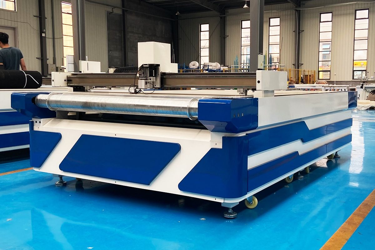
Oscillating Knife Cutting Foam Guide
Foam is widely used in packaging, insulation, automotive interiors, protective inserts, furniture, sporting goods, advertising displays, and many other applications. However, cutting foam accurately can be challenging because the material may compress, stretch, tear, melt, or deform during processing. Traditional manual cutting methods often produce inconsistent dimensions and rough edges, especially when manufacturing complex shapes or large production batches. Oscillating knife cutting provides a precise, flexible, and efficient alternative for converting many types of foam into finished components.
Oscillating knife cutting machines use a rapidly reciprocating blade to separate material without generating the high temperatures associated with laser cutting. Because the process is mechanical and generally produces no burned edges, smoke, or heat-affected zones, it is well suited to temperature-sensitive foam products. Depending on the blade, cutting parameters, material density, and machine configuration, the equipment can process materials such as EVA foam, EPE foam, PE foam, polyurethane foam, sponge, neoprene, acoustic foam, and certain foam composites. Digital CNC control also allows the machine to cut contours, slots, holes, notches, and customized patterns directly from design files.
Choosing the correct cutting system requires more than comparing machine speed or table size. Foam thickness, density, hardness, cell structure, backing layers, required edge quality, dimensional tolerance, and production volume can all influence the final result. The appropriate blade type, oscillation frequency, cutting speed, tool path, vacuum holding system, and material-feeding method must work together to achieve stable processing.
This oscillating knife cutting foam guide explains how the technology works, which foam materials it can process, its primary advantages and limitations, and the factors that affect cutting quality. It also covers tool selection, machine configurations, common applications, operating practices, maintenance, and purchasing considerations. Understanding these elements will help manufacturers select suitable equipment, reduce material waste, improve product consistency, and build a safer and more efficient foam-cutting workflow.
Table of Contents
What Is Oscillating Knife Foam Cutting?
Oscillating knife foam cutting is a digital machining process that uses a rapidly reciprocating blade to cut foam sheets, blocks, and laminated foam materials along programmed paths. Unlike laser cutting, the process does not rely on heat to separate the material. This helps prevent melting, burning, discoloration, smoke, and heat-affected edges, making it particularly useful for temperature-sensitive foam products. With the correct blade, tooling, and cutting parameters, oscillating knife cutting systems can produce clean contours, accurate dimensions, and repeatable parts for prototypes, customized orders, and continuous production.
Definition of Oscillating Knife Cutting
Oscillating knife tools contain a blade that moves rapidly upward and downward while the cutting head travels across the material. This reciprocating action allows the blade to penetrate and separate soft, flexible, porous, or semi-rigid materials with less dragging than a conventional fixed blade. Because the blade actively cuts through the foam, it can reduce compression, tearing, and edge distortion when the tool is correctly matched to the material.
Oscillating tools are available in electric and pneumatic configurations. Electric oscillating tools are commonly used for general-purpose foam cutting, while pneumatic tools can provide stronger cutting action for thicker, denser, or more resistant materials. Blade length, blade shape, tip geometry, oscillation frequency, and cutting depth must be selected according to the foam’s thickness, density, hardness, cell structure, and required edge quality.
The process typically creates a narrow cutting path because there is no rotating cutter diameter or wide heat-affected zone. This makes it possible to nest parts closely together and improve material utilization. It can also produce intricate outlines, internal cutouts, slots, notches, and holes. However, extremely small features and tight internal corners remain limited by blade thickness, blade geometry, foam stability, and the minimum turning radius the tool can achieve without distorting the material.
The Role of CNC Control
CNC control converts digital design files into coordinated machine movements. After a drawing is created or imported, software processes the geometry, arranges the parts on the foam sheet, and generates cutting paths. The controller then guides the cutting head along the X and Y axes while managing tool lifting, plunging, cutting speed, acceleration, oscillation, and cutting sequence.
This digital workflow enables the machine to reproduce the same component with consistent dimensions across multiple production batches. Operators can modify part sizes, quantities, nesting layouts, and cutting parameters without producing a physical die. As a result, oscillating knife cutting is especially suitable for prototyping, short production runs, customized products, and frequently changing designs.
CNC control can also coordinate multiple tools and optional machine functions. A system may include an oscillating knife, drag knife, creasing wheel, milling spindle, marking pen, or punching tool. Automatic tool calibration and camera registration can improve positioning accuracy, while conveyor feeding can support continuous processing of rolled or long foam materials. Nesting software helps arrange components efficiently to reduce offcuts and overall material consumption.
Accurate CNC movement alone does not guarantee accurate foam parts. Soft foam may shift, compress, stretch, or lift during cutting. Vacuum adsorption, zoned suction, suitable underlay materials, and proper cutting sequences are therefore essential for stable production. Manufacturers must optimize the complete process rather than relying only on the machine’s nominal positioning accuracy.
Scope of the Process
Oscillating knife cutting is mainly used for two-dimensional profile cutting of foam sheets and relatively flat foam products. Depending on the machine configuration, it can process EVA foam, EPE foam, PE foam, polyurethane foam, sponge, neoprene, acoustic foam, packaging foam, filter foam, rubber foam, and selected laminated or adhesive-backed materials. Typical products include protective packaging inserts, tool-case liners, seals, gaskets, insulation components, sound-absorbing panels, automotive interior parts, sports padding, footwear components, and customized display materials.
The process can perform outer contour cutting, internal openings, slots, notches, and repeated pattern cutting. It may also support kiss cutting, in which only the upper foam or adhesive layer is cut while the backing liner remains intact. When fitted with additional tools, the same machine may mark identification lines, crease compatible materials, drill or punch selected features, or use a spindle for operations that an oscillating blade cannot complete effectively.
Its suitability nevertheless depends on the material and component geometry. Very thick or high-density foam may require a longer blade, a stronger pneumatic tool, reduced cutting speed, or multiple passes. Foam with reinforcing fabric, hard laminated skins, strong adhesive layers, or abrasive fillers may increase blade wear. Extremely soft foam may deform under the blade, while rigid foam may chip or require routing instead. Standard oscillating knife cutting machines are generally intended for 2D profiles rather than fully sculpted three-dimensional surfaces, deep cavities, or complex variable-depth contours.
Oscillating knife foam cutting combines a reciprocating blade with CNC-controlled motion to process foam without applying heat. It offers clean edges, narrow cutting paths, rapid design changes, efficient nesting, and repeatable digital production without the cost and storage requirements of physical cutting dies. Its capabilities can extend from simple outlines to internal cutouts, slots, notches, and selected kiss-cutting operations.
Successful processing depends on matching the blade, tool type, cutting parameters, vacuum system, and software settings to the foam’s properties. Although the technology is versatile, it is not equally suitable for every foam or geometry. Material testing remains essential for verifying dimensional accuracy, edge quality, processing speed, blade life, and production stability before full-scale manufacturing.
How Does Oscillating Knife Foam Cutting Work?
Oscillating knife foam cutting combines a rapidly reciprocating blade with computer-controlled machine movement. The blade repeatedly enters and withdraws from the foam while the cutting head follows a programmed path. This active slicing action separates the material mechanically, without using the heat associated with laser cutting. The machine coordinates blade oscillation, travel direction, cutting depth, and tool orientation to produce accurate contours while limiting compression, tearing, and deformation.
Before cutting begins, a digital design is imported into the machine software. The software generates toolpaths, determines the cutting sequence, and assigns suitable parameters such as speed, acceleration, blade depth, and oscillation settings. The foam is placed on a cutting table and usually secured by a vacuum adsorption system. Once the material is positioned and the tool is calibrated, the CNC system controls the entire cutting cycle.
Blade Oscillation and Material Separation
The blade moves rapidly up and down inside the tool holder. Rather than being dragged continuously through the foam like a static knife, the oscillating blade performs a series of fast cutting strokes. Each downward stroke penetrates and separates the material, while the upward motion helps release friction and clear the blade for the next stroke. This repeated action allows the knife to cut foam more efficiently while reducing pulling, bunching, and edge distortion.
Because the process separates material mechanically, it generally does not produce melting, carbonization, smoke, or a heat-affected zone. This is particularly valuable when processing heat-sensitive materials such as EVA foam, EPE foam, PE foam, polyurethane foam, neoprene, sponge, and acoustic foam. It can also help preserve the original color, texture, and cellular structure near the cut edge.
The quality of material separation depends on the relationship between oscillation frequency, oscillation amplitude, blade geometry, cutting speed, and foam properties. Soft, low-density foam may require settings that minimize compression and material movement. Thick or dense foam may need a longer blade, more powerful oscillation, slower travel, or multiple passes. If the blade is too short, dull, flexible, or unsuitable for the material, it may deflect and produce tapered edges or inaccurate dimensions.
The vacuum table also plays an important role. Foam can lift or shift when contacted by the blade, particularly when it is lightweight, porous, or cut into small parts. Vacuum adsorption, protective film, localized clamping, or an appropriate sacrificial underlay can help stabilize the workpiece. The blade typically penetrates slightly into the cutting mat to ensure complete separation without damaging the machine table.
Coordinated X, Y, and Z Movement
The machine uses coordinated X-, Y-, and Z-axis movement to control the position and depth of the cutting tool. The X and Y axes move the cutting head horizontally across the worktable, allowing it to follow straight lines, curves, circles, slots, and complex contours. The Z-axis raises and lowers the tool to establish the cutting depth, enter the foam, retract between separate contours, and avoid unwanted marks while moving to the next cutting location.
The CNC controller synchronizes these movements with the digital toolpath. For a continuous outer profile, the blade lowers into the material and follows the programmed contour in the X and Y directions. When the contour is complete, the Z-axis lifts the blade before the head travels to another feature. For internal openings, the machine can begin at a designated entry point, cut the feature, retract, and continue to the next operation.
Accurate Z-axis control is especially important when processing foams of different thicknesses or laminated materials. The blade must penetrate deeply enough to cut through the entire foam layer, but excessive depth can increase blade wear, damage the underlay, or reduce cutting stability. For kiss cutting, the machine cuts through only the upper foam or adhesive layer while leaving the backing liner intact. This operation requires careful calibration of material thickness, blade extension, and cutting depth.
Motion settings must also account for the behavior of flexible materials. Excessive acceleration can cause the foam to shift, while cutting too quickly can bend the blade or leave incompletely separated areas. The controller therefore balances productivity with edge quality and dimensional accuracy. Smooth axis motion, proper path planning, and stable material fixation are essential for consistent results.
Tangential Blade Orientation
Oscillating blades have a defined cutting edge and must remain aligned with the direction of travel. A tangential control system rotates the knife around its vertical axis so that the blade continuously points along the programmed cutting path. As the cutting head changes direction, the controller adjusts the blade angle before or during the movement.
Tangential orientation is particularly important when cutting curves, corners, narrow slots, and intricate shapes. If the blade is not correctly aligned, it may be forced sideways through the foam. This can cause blade deflection, enlarged corners, torn edges, compressed material, or inaccurate contours. Active blade rotation reduces lateral force and helps the knife follow the intended geometry more precisely.
At a gradual curve, the tangential axis can rotate smoothly while the X and Y axes continue moving. At a sharp corner, the machine may slow down, lift the blade slightly, rotate it to the new direction, and then resume cutting. Cutting software may also apply corner compensation, overcut settings, or optimized entry and exit paths. These functions help reduce uncut fibers, rounded internal corners, and material distortion.
Blade thickness and shape still impose practical limits. Very small radii or narrow internal features may be difficult to reproduce if the blade cannot rotate inside the available space. For these geometries, the machine may require a narrower blade, an alternative tool, or a modified design with a larger corner radius.
Electric and Pneumatic Oscillation
Oscillating knife tools are generally powered electrically or pneumatically. Both types create the reciprocating blade motion required to separate foam, but their operating characteristics and suitable applications can differ.
Electric oscillating tools use an electric motor to drive the blade. They are commonly selected for general-purpose cutting of soft to medium-density foam and other flexible materials. Electric systems usually provide precise control, convenient integration, relatively quiet operation, and no requirement for a dedicated compressed-air supply at the tool. They are suitable for many packaging, gasket, insulation, and customized foam applications.
Pneumatic oscillating tools use compressed air to generate the blade movement. They can provide strong cutting action and are often considered for thick, dense, resilient, or multilayer foam that places greater resistance on the blade. A pneumatic tool may improve penetration and cutting stability in demanding applications, but it requires a clean, dry, adequately sized compressed-air supply. Air pressure, flow capacity, filtration, and maintenance can affect long-term performance.
Neither tool type is universally better. The correct choice depends on foam thickness, density, hardness, reinforcement, required cutting speed, edge-quality standards, and daily production volume. Actual sample testing is the most reliable way to determine whether an electric or pneumatic tool delivers the required balance of accuracy, productivity, blade life, noise, and operating cost.
Oscillating knife foam cutting works by combining rapid vertical blade strokes with synchronized CNC movement. The oscillating action separates the foam without heat, while the X and Y axes guide the tool along the programmed contour. The Z-axis controls penetration and retraction, and tangential rotation keeps the blade aligned with the direction of travel.
Electric tools are suitable for many general foam-cutting applications, while pneumatic systems may provide stronger cutting action for thicker or more resistant materials. However, successful processing depends on the complete setup, including blade geometry, cutting speed, oscillation settings, depth calibration, vacuum fixation, toolpath strategy, and foam characteristics. Careful parameter optimization and material testing are essential for achieving clean edges, accurate dimensions, efficient production, and consistent cutting quality.
Main Components of Oscillating Knife Foam Cutting Machines
Oscillating knife foam cutting machines are an integrated digital production system rather than a single cutting tool. Their accuracy, speed, and reliability depend on the coordinated performance of the mechanical structure, motion system, cutting head, material-holding equipment, CNC controller, and processing software. Optional feeding, positioning, and safety equipment can further adapt the machine to different foam formats and production requirements.
Understanding these components helps manufacturers compare machine configurations more effectively. A high oscillation speed or large working area alone does not guarantee good results. The machine must maintain smooth movement, hold the foam securely, orient the blade correctly, and convert digital designs into stable cutting operations.
Machine Frame, Gantry, and Motion System
The machine frame provides the structural foundation for the cutting table, gantry, drive components, and electrical equipment. It must remain rigid and dimensionally stable during acceleration, deceleration, and continuous production. A properly manufactured frame helps reduce vibration, gantry misalignment, and positioning errors that could affect the dimensions or edge quality of finished foam parts.
The gantry spans the working area and carries the cutting head. It moves along one machine axis while the cutting carriage travels across the gantry on the other axis. The gantry should combine rigidity with manageable weight. A heavy but poorly controlled gantry can limit acceleration, while an excessively light or flexible structure may vibrate or deform during high-speed movement.
Linear guide rails support accurate and repeatable travel. Depending on the machine design and working area, power transmission may use rack-and-pinion drives, timing belts, ball screws, or a combination of these systems. Servo motors are commonly used when fast response, accurate positioning, and closed-loop motion control are required. Some machines use stepper or hybrid servo systems for applications with less demanding performance requirements.
The motion system must provide more than high maximum speed. Smooth acceleration, synchronized axis movement, minimal backlash, and stable low-speed control are equally important. These characteristics help the machine follow curves, small features, and sharp directional changes without pulling the foam or forcing the blade sideways.
Cutting Head and Blade Holder
The cutting head supports the oscillating tool and positions it above the material. It normally includes the oscillation mechanism, blade holder, vertical lifting assembly, and tangential rotation system. Depending on the machine configuration, the head may carry one tool or several interchangeable tools for cutting, creasing, marking, routing, or punching.
The blade holder secures the blade and transfers the oscillating motion to its cutting edge. It must maintain firm blade alignment while allowing operators to replace worn blades safely and efficiently. Any looseness in the holder can cause vibration, blade deflection, tapered edges, inaccurate corners, or premature blade wear.
Blade selection is determined by foam thickness, density, hardness, cell structure, and required geometry. Long blades can process thicker foam but may deflect more easily if the material is dense or the cutting speed is too high. Narrow blades can negotiate smaller curves, while wider or more rigid blades may provide better stability on straight cuts. The blade extension should be only long enough to penetrate the material and cutting underlay reliably.
The head’s tangential axis rotates the blade so that its cutting edge remains aligned with the direction of travel. This is essential because oscillating knives cannot cut accurately when pushed sideways through the foam. At sharp corners, the machine may slow down, lift the blade slightly, rotate it, and continue in the new direction. Some cutting heads also include automatic tool-height sensing or calibration functions that help establish the correct cutting depth.
Electric oscillating tools are commonly used for many soft and medium-density foams. Pneumatic tools can provide stronger cutting action for thicker, denser, or more resistant materials but require a suitable compressed-air supply. The cutting head should therefore be selected according to actual sample results rather than oscillation specifications alone.
Vacuum Table and Cutting Underlay
Foam must remain flat and stationary while the cutting head moves across it. A vacuum table creates negative pressure beneath the material, helping prevent lifting, sliding, stretching, or shifting. This is particularly important when cutting lightweight sheets, porous foam, small components, or closely nested patterns.
Vacuum tables are often divided into independently controlled zones. Operators can activate only the zones covered by the workpiece, concentrating suction where it is needed and reducing unnecessary airflow loss. This is helpful when cutting material that is smaller than the machine’s full working area. The required vacuum capacity depends on the table size, foam porosity, material thickness, part geometry, and amount of exposed table surface.
Because open-cell and highly porous foam can allow air to pass through easily, vacuum holding may be more difficult than with dense, closed-cell materials. In these cases, operators may cover unused table areas, apply a temporary protective film, adjust vacuum zoning, or use additional edge restraint. Proper material preparation is essential because even an accurate machine cannot produce consistent parts if the foam moves during cutting.
A replaceable cutting underlay is installed between the foam and the machine table. This porous sacrificial layer allows vacuum airflow to reach the material while protecting the table from the blade. The blade can penetrate slightly into the underlay to ensure complete separation. Over time, repeated cutting damages the surface and reduces holding consistency, so the underlay must be inspected, cleaned, resurfaced when appropriate, and replaced when excessively worn.
Control System and Software
The control system coordinates the movement of the machine axes, cutting head, tangential rotation, vacuum equipment, and optional accessories. It interprets the generated toolpath and controls travel speed, acceleration, cutting depth, tool lifting, blade orientation, and processing sequence. A reliable controller helps maintain smooth motion and repeatable cutting performance during long production runs.
Cutting software connects design preparation with machine operation. It can import common vector or CAD file formats, inspect geometry, assign tools, define cutting parameters, and generate optimized paths. Depending on the software package, it may also provide automatic nesting, common-line cutting, part labeling, quantity management, material libraries, and production-time estimation.
Nesting software arranges components efficiently within the available foam sheet. Close and logical placement can reduce offcuts, lower material costs, and shorten non-cutting travel. However, spacing must account for foam stability, blade turning requirements, and the possibility that narrow areas between parts may move after being separated.
A material and process database allows operators to store suitable settings for different foam types and thicknesses. These settings may include cutting speed, oscillation mode, acceleration, blade type, cutting depth, corner behavior, and the number of passes. Saved parameter sets reduce setup time and help different operators achieve more consistent results.
The user interface should also support job previews, origin setting, tool calibration, manual movement, production monitoring, alarm display, and fault diagnosis. Network connectivity, barcode job loading, and integration with production management systems may be valuable in automated factories, but these features should be evaluated according to actual workflow requirements.
Optional Supporting Equipment
Optional equipment can expand the machine’s capabilities or improve material handling. A conveyor table and automatic feeding system allow the machine to process foam supplied in rolls or long sheets. After one cutting area is completed, the conveyor advances the material for the next cycle. This configuration is useful for continuous production but requires accurate feeding and software compensation to maintain alignment between sections.
A roll holder or unwinding rack supports flexible foam supplied in rolls. Tension control and edge-guiding devices can help prevent wrinkles, skewing, and uneven feeding. For rigid foam sheets or large blocks, lifting tables, loading carts, or automated handling systems may reduce manual work and protect the material from damage.
Camera registration systems detect printed marks, material edges, or recognizable features and adjust the cutting path accordingly. They are useful when the foam is printed, pre-laminated, or positioned with limited repeatability. Projection systems can display part outlines or loading locations directly on the work surface, helping operators place foam correctly and sort finished components.
Machines equipped with pneumatic oscillating tools require an air compressor and air-treatment components capable of supplying the specified pressure and flow. Filters and dryers help prevent moisture and contamination from affecting pneumatic performance. If the machine also uses a routing spindle, a dust-extraction system may be necessary to collect chips and airborne particles generated during milling.
Additional options may include a marking pen, creasing wheel, perforating tool, punching tool, milling spindle, automatic tool-changing system, barcode scanner, labeling device, or extended material-collection table. Safety equipment can include emergency-stop controls, protective covers, warning indicators, safety mats, light curtains, or enclosed working areas. The required protection depends on the machine configuration, installed tools, operating environment, and applicable safety regulations.
The main components of oscillating knife foam cutting machines work together as a unified system. The frame and gantry provide structural stability, while the motion system guides the cutting head accurately across the work area. The cutting head generates the oscillating action, holds the selected blade, controls penetration depth, and rotates the blade to follow the cutting direction.
The vacuum table stabilizes the foam, and the cutting underlay supports airflow while protecting the machine surface. The control system and software convert digital designs into coordinated machine movements, manage process parameters, and optimize material usage through efficient nesting. Optional feeding, vision, handling, auxiliary tooling, and safety equipment can adapt the system to specialized applications or higher production volumes.
When selecting a machine, manufacturers should evaluate how these components perform together under actual processing conditions. Cutting tests using the intended foam, thicknesses, part geometries, and quality standards provide a more reliable basis for equipment selection than comparing individual specifications in isolation.
Foam Types and Their Cutting Suitability
Foam is not a single material category with uniform cutting behavior. Different foams vary in density, hardness, elasticity, cell structure, abrasiveness, thermal sensitivity, and compressibility. These properties affect how easily a blade penetrates the material, how well the foam remains flat, and whether the finished edge is clean, tapered, compressed, or torn.
Oscillating knife cutting is suitable for many flexible, semi-rigid, and selected rigid foams because it separates the material mechanically without creating a heat-affected zone. However, machine configuration and processing parameters must be matched to the specific material. Blade geometry, cutting depth, oscillation strength, travel speed, vacuum holding, and toolpath strategy should be verified through sample testing before production.
Flexible Polyurethane Foam
Flexible polyurethane foam is commonly used in furniture, mattresses, automotive seating, protective packaging, acoustic products, filters, and cleaning sponges. It is generally lightweight, compressible, and available in a wide range of densities, firmness levels, thicknesses, and cell structures. Open-cell polyurethane foam is especially common in cushioning and sound-absorption applications.
Oscillating knife cutting is well suited to many flexible polyurethane foams because the reciprocating blade can slice through the cellular structure without melting the edges. It can create external profiles, openings, slots, ventilation features, and customized packaging cavities. Digital cutting is particularly useful for prototypes, small batches, and products requiring frequent design changes.
Very soft foam can compress or move as the blade enters it. Excessive cutting speed, rapid acceleration, or insufficient material holding may cause distorted dimensions and uneven contours. Thick foam also increases the risk of blade bending, which can produce a wider opening at the top than at the bottom. A long, narrow, sharp blade, controlled acceleration, suitable vacuum fixation, and minimal blade extension beyond the required depth can improve cutting stability.
Reticulated filter foam and coarse open-cell foam may behave differently from fine-cell cushioning foam. Their open structure can reduce vacuum-holding effectiveness and allow the blade to pull individual cell strands. Material testing is therefore necessary to determine the appropriate tool, cutting direction, and speed.
Polyethylene Foam
Polyethylene foam is a closed-cell material widely used for protective packaging, equipment cases, insulation, flotation products, expansion joints, sports equipment, and industrial cushioning. It is available in non-cross-linked and cross-linked forms, with densities ranging from lightweight packaging grades to firm, durable foam boards.
Many polyethylene foams respond well to oscillating knife cutting. Their closed-cell structure generally provides better dimensional stability than very soft open-cell foams, allowing the machine to produce clean profiles and fitted packaging inserts. The absence of processing heat also helps avoid melted, hardened, or discolored edges.
Cross-linked polyethylene foam can be denser, smoother, and more resilient than non-cross-linked grades. Higher-density material may require a more rigid blade, a stronger oscillating tool, slower travel speed, or multiple passes. Thick stacks should be evaluated carefully because the layers can shift or the blade can deflect. Cutting individual sheets or securely bonded stacks usually provides better consistency.
Polyethylene foam is often supplied in multiple colors and laminated layers. This makes it popular for presentation packaging and shadow-board inserts, where contrasting colors reveal whether a tool is missing. Accurate depth control can also support partial-depth cutting, although complex recessed pockets may require routing, lamination of pre-cut layers, or another fabrication method.
EVA Foam
Ethylene-vinyl acetate, commonly called EVA foam, is used in footwear, sports padding, exercise mats, protective cases, toys, cosplay products, marine applications, and industrial components. It is flexible and resilient but is often denser and more resistant to cutting than lightweight packaging foam.
Oscillating knife systems can cut EVA sheets into accurate contours, holes, slots, pads, and layered inserts. The cold mechanical process helps preserve the material’s color and surface texture while avoiding the melted or darkened edges that thermal cutting may create. CNC control is valuable for products that require repeated patterns or multiple size variations.
The cutting difficulty depends strongly on the EVA formulation, density, hardness, and thickness. Soft EVA may compress around the blade, while firm EVA can create greater resistance and accelerate blade wear. A powerful electric or pneumatic oscillating tool, a short and rigid blade, controlled travel speed, and secure vacuum holding may be needed for dense grades.
EVA’s elasticity can cause small openings to close slightly after the blade passes. Consequently, the final dimensions may not exactly match the programmed path. Process compensation, test cuts, and dimensional inspection are important when parts have tight tolerances. Very small holes, deep pockets, bevels, and three-dimensional features may be better produced with a punch, router, or combined cutting system.
Expanded Polypropylene Foam
Expanded polypropylene foam, or EPP, is a lightweight bead foam known for impact absorption, energy recovery, chemical resistance, and repeated-use durability. It is commonly used in automotive components, reusable packaging, protective cases, HVAC parts, sports products, and material-handling containers.
Oscillating knife cutting can process many EPP sheets and relatively flat molded sections, particularly when producing prototypes, inserts, dividers, and two-dimensional profiles. Because the method does not apply concentrated heat, it avoids thermally fused edges and heat-related deformation.
However, EPP’s fused-bead structure can make cutting behavior less uniform than that of fine-cell foam. A dull or poorly selected blade may pull out beads, leave a rough surface, or tear material along the cut edge. The risk increases with coarse bead structures, low-density grades, thick material, and small internal details.
A sharp blade, appropriate oscillation strength, moderate cutting speed, and stable support can reduce bead breakout. The part should be inspected on both the upper and lower surfaces because blade deflection may not be visible from the top. Complex molded EPP components with deep three-dimensional geometry usually require specialized trimming, milling, waterjet cutting, or purpose-designed fixtures rather than a standard flatbed knife cutter.
Expanded and Extruded Polystyrene
Expanded polystyrene and extruded polystyrene are rigid thermoplastic foams used in packaging, insulation, architectural models, signage, displays, construction, and protective components. Expanded polystyrene, or EPS, has a visible fused-bead structure. Extruded polystyrene, or XPS, has a finer and more continuous closed-cell structure.
Oscillating knife cutting can be suitable for relatively thin EPS and XPS sheets, simple profiles, prototypes, gaskets, models, and flat insulation components. XPS often provides a smoother cut than coarse-bead EPS because of its more uniform internal structure. The process avoids the fumes and melted surfaces associated with thermal cutting.
Both materials are relatively rigid and can be brittle. EPS may shed beads or chip along the edge if the blade is dull, the cutting direction changes abruptly, or the foam is inadequately supported. XPS can crack, crush, or develop torn edges if the blade geometry and cutting speed are unsuitable. Sharp blades, gentle acceleration, controlled cornering, and a clean cutting underlay can improve results.
Oscillating knife cutting is not always the most efficient choice for very thick polystyrene blocks or sculpted three-dimensional forms. Hot-wire equipment is frequently used for straight cuts and large contours in compatible polystyrene products, while routing may be selected for pockets, channels, bevels, and detailed three-dimensional shapes. The correct method depends on the required geometry, surface finish, productivity, and applicable ventilation and safety controls.
Elastomeric and Sponge Rubber Foams
Elastomeric foams include materials such as neoprene foam, EPDM foam, nitrile rubber foam, silicone foam, and certain blended sponge-rubber products. They are used for seals, gaskets, thermal insulation, vibration control, weather stripping, protective padding, marine products, and electrical enclosures.
Oscillating knife cutting is an effective method for producing many flat seals, pads, strips, and gasket profiles from elastomeric foam sheets. It can process both closed-cell and open-cell products without introducing heat, which helps preserve surface appearance and material properties near the cut edge.
These foams can be elastic, tacky, dense, or highly frictional. The blade may drag the material, stretch narrow features, or cause small holes to deform after cutting. Dense rubber foam can also increase cutting resistance and blade wear. Thin, sharp blades, strong tangential control, reduced acceleration, and proper workpiece fixation are important for maintaining dimensional accuracy.
Adhesive-backed sponge rubber introduces additional challenges. The adhesive can accumulate on the blade, increase friction, and transfer contamination to other parts. Kiss cutting requires precise depth control so that the foam and adhesive are cut while the release liner remains intact. Test cutting is essential because nominal material thickness can vary across a roll or sheet.
Structural and Rigid Foam Cores
Structural and rigid foam cores are used in composite panels, marine structures, wind-energy components, transportation products, insulation systems, aerospace components, tooling, and sandwich construction. This category may include rigid PVC foam, PET foam, PMI foam, SAN foam, rigid polyurethane foam, polyisocyanurate foam, and phenolic foam.
Oscillating knives can cut selected grades and thicknesses into flat profiles, kit components, core inserts, and simple openings. It produces relatively little dust compared with routing and does not introduce a heat-affected edge. This can be beneficial when preparing foam-core kits for subsequent lamination or composite assembly.
Suitability varies considerably within this category. Some structural cores are easy to slice, while others are too hard, brittle, abrasive, or thick for efficient oscillating knife processing. A dense core may resist the blade and cause deflection, whereas a brittle core may chip or crack. Reinforced scrims, resin-rich surfaces, and fire-retardant additives can further affect blade life and edge quality.
Oscillating knives are primarily suited to through-cutting flat profiles. Bevels, chamfers, drainage grooves, drilled holes, pockets, and three-dimensional contours often require a CNC router, drilling unit, or specialized multi-axis machine. A hybrid system combining oscillating knives with a spindle can provide greater flexibility. When routing foam cores, appropriate dust collection and material-specific safety procedures are necessary.
Laminated, Faced, and Adhesive-Backed Foams
Foam products are frequently combined with aluminum foil, films, textiles, fiberglass facings, pressure-sensitive adhesives, release liners, decorative surfaces, or additional foam layers. These constructions are used in insulation, automotive interiors, HVAC systems, medical products, protective packaging, seals, and acoustic components.
Oscillating knife cutting can process many laminated materials in a single digital operation, but the complete construction must be evaluated rather than considering only the foam core. A facing that is easy to cut separately may behave differently after lamination. The blade must penetrate every layer without pulling the facing, separating the bond, or compressing the foam excessively.
Thin films and textile facings may stretch or lift if the cutting sequence is poorly planned. Metal foil can wrinkle, tear, or dull the blade. Fiberglass-reinforced layers may be abrasive and require specialized tooling and suitable exposure controls. Weakly bonded laminates may delaminate near corners or narrow features. Cutting from the correct side, using a sharp blade, reducing acceleration, and maintaining strong vacuum support can improve results.
Adhesive-backed foam can be through-cut into individual components or kiss-cut so that the release liner remains intact. Accurate tool-height calibration is critical because variations in foam thickness, adhesive coating, or liner thickness can lead to incomplete cuts or damage to the backing. Adhesive residue should be monitored and removed from the blade holder according to the manufacturer’s maintenance instructions.
For multilayer foam assemblies, manufacturers should inspect the top edge, bottom edge, facing condition, adhesive bond, and dimensional recovery after cutting. A sample that appears clean immediately after processing may change shape as compressed foam relaxes. Production approval should therefore consider both immediate appearance and the part’s condition after recovery.
Oscillating knife cutting technology can process a broad range of foam materials, including flexible polyurethane, polyethylene, EVA, EPP, polystyrene, sponge rubber, structural cores, and laminated constructions. Its heat-free cutting action helps prevent melting, burning, discoloration, and heat-affected edges, making it especially valuable for temperature-sensitive materials.
Cutting suitability nevertheless depends on more than the generic foam name. Density, hardness, cell structure, elasticity, thickness, reinforcement, adhesive layers, and required geometry all influence performance. Soft foam may compress or shift, dense foam may deflect the blade, bead foam may tear, and laminated foam may delaminate or contaminate the cutting tool.
For reliable production, manufacturers should test the exact material grade and thickness using the intended blade, machine configuration, and holding method. The test should evaluate cutting speed, edge quality, upper-to-lower dimensional consistency, blade wear, material recovery, and finished-part tolerances. When the required features exceed the practical capabilities of oscillating knives, routing, punching, drilling, hot-wire cutting, or a hybrid process may provide a more suitable solution.
Material Properties That Affect Foam Cutting
Foam-cutting performance is determined by the physical behavior of the material as much as by the capabilities of the machine. Two foams with similar appearances or chemical compositions may require very different blades, cutting speeds, oscillation settings, and holding methods. Density, hardness, cell structure, thickness, elasticity, abrasiveness, and surface construction all influence how the blade penetrates the material and how the finished part behaves after cutting.
Understanding these properties makes it easier to select suitable tooling and establish reliable parameters. It also helps explain common problems such as incomplete separation, tapered edges, torn cells, compressed dimensions, material movement, rapid blade wear, and adhesive buildup. The exact foam grade should always be tested because general material names do not fully describe cutting behavior.
Density, Hardness, and Cutting Resistance
Density describes the amount of material contained within a given volume, while hardness describes its resistance to indentation or compression. These properties are related in some products but are not interchangeable. A high-density foam is not necessarily harder than every low-density foam, and two materials with the same density may have different firmness, elasticity, and cutting resistance.
Low-density foam is often easy for a blade to penetrate, but its light weight and limited structural stability can make it difficult to hold in position. The cutting head may compress, lift, or drag the material, especially around narrow features and small parts. Vacuum suction, gentle acceleration, and a sharp blade can help prevent movement and distortion.
High-density or firm foam generally creates greater resistance against the blade. It may require a more powerful oscillating tool, reduced travel speed, shorter blade extension, or multiple cutting passes. If resistance exceeds the blade’s rigidity, the blade can bend as it travels through the material. This may produce angled sidewalls, mismatched dimensions between the upper and lower surfaces, or incomplete cuts near corners.
Cutting resistance is also affected by tensile strength, tear strength, elongation, resilience, cell-wall construction, fillers, and reinforcement. A soft but highly elastic foam may grip the blade more strongly than a harder but brittle material. Machine settings should therefore be based on actual cutting tests rather than density or hardness values alone.
Open-Cell and Closed-Cell Structures
Open-cell foam contains interconnected pores through which air can pass. Flexible polyurethane foam, reticulated filter foam, and many acoustic foams are common examples. These materials are often soft, lightweight, and compressible, but their cutting behavior varies according to cell size, density, and the strength of the cellular network.
Large or coarse open cells can tear or pull apart if the blade is dull or moving too quickly. Fine-cell structures may provide a smoother edge but can still compress under the blade. Because air passes through open-cell foam, a vacuum table may have difficulty creating sufficient holding force. Covering unused table zones, using an appropriate underlay, or applying a temporary air-impermeable film can improve material fixation.
Closed-cell foam consists mainly of sealed cells that limit airflow and moisture penetration. Polyethylene, EVA, EPP, neoprene, and many structural foam cores are available in closed-cell forms. These materials usually hold their shape more effectively than very soft open-cell foam, and their less permeable surfaces can allow the vacuum system to maintain useful pressure beneath the sheet.
However, closed-cell foam may be resilient, dense, or highly elastic. The material can grip the blade, spring back after cutting, or close around narrow cut lines. Internal gas pressure and cell-wall recovery can also affect the apparent width of small openings. A clean edge therefore depends on suitable blade geometry, strong tangential control, adequate oscillation, and cutting parameters that minimize sideways loading.
Cell structure also affects the visible finish. Bead foams such as EPS and EPP may lose individual beads along the edge, while fine-cell cross-linked foam may produce a smoother surface. The manufacturer should inspect both the cut edge and the dimensional condition of the part after it has fully recovered.
Thickness and Thickness Variation
Material thickness determines the required blade length, cutting depth, tool clearance, and amount of resistance acting along the blade. As foam becomes thicker, a longer blade is needed, but longer blades are generally more vulnerable to bending. This increases the possibility of tapered edges, bottom-surface deviation, or blade breakage when processing dense materials.
Blade extension should be kept as short as practical while still allowing the knife to penetrate the entire foam layer and enter the sacrificial underlay slightly. Excessive penetration increases friction and underlay wear, while insufficient penetration leaves uncut material on the lower surface. For thick or resistant foam, slower movement, reduced acceleration, a more rigid blade, or multiple passes may improve consistency.
Nominal thickness does not always equal actual thickness. Flexible foam sheets can vary because of manufacturing tolerances, storage conditions, compression during transport, or uneven surfaces. Laminated products may also have local differences in adhesive, facing, or foam thickness. These variations can cause incomplete through-cuts when the Z-axis depth is set too shallow.
Thickness variation is especially important in kiss cutting. The blade must cut through the foam and adhesive layer without penetrating the release liner. Even a small change in material thickness can produce incomplete separation in one area and damaged backing in another. Automatic surface measurement, careful tool calibration, controlled material quality, and conservative depth settings can improve process reliability.
Very thick blocks may exceed the practical blade length or Z-axis clearance of flatbed oscillating knife cutting machines. They may also require specialized long-blade tools or alternative processes such as band-knife cutting, contour cutting, hot-wire cutting for compatible materials, or CNC routing.
Compression and Elastic Recovery
Foam compresses when contacted by the blade, tool foot, vacuum system, or material-handling equipment. The amount of compression depends on the foam’s firmness, thickness, cellular structure, and resilience. If the material compresses unevenly during cutting, the programmed geometry may not match the final relaxed dimensions.
Soft foam may collapse ahead of the blade and then expand after the tool passes. This can cause curved profiles to become uneven and narrow features to shift. Excessive acceleration can stretch or push the foam, while an overly aggressive hold-down device can compress it before cutting. Stable but non-deforming support is therefore essential.
Elastic recovery describes the foam’s ability to return toward its original shape after the load is removed. Materials with strong recovery may close around the blade, making small holes or slots appear narrower than the programmed dimensions. They can also grip the blade, increase friction, and pull small components out of position.
Dimensional inspection should not always be performed immediately after cutting. Some foams require a short conditioning period before their dimensions stabilize. The finished part should be measured in its relaxed state and under the same environmental and loading conditions specified for the application. If necessary, software compensation can adjust the cutting path, but compensation should be based on repeatable test results rather than a single measurement.
Part orientation and cutting sequence can also affect recovery. Narrow sections may deform after surrounding waste is removed, and closely nested parts may lose support during the cutting cycle. Toolpaths should be planned so that the material remains stable for as long as possible.
Abrasiveness, Tackiness, and Surface Layers
Some foams contain mineral fillers, flame-retardant additives, reinforcing fibers, coarse cell structures, or abrasive surface treatments. These features can wear the cutting edge more rapidly than the base polymer alone would suggest. A blade may still appear intact while becoming too dull to produce clean edges or accurate dimensions.
Blade condition should therefore be monitored through cut quality, cutting resistance, and production time rather than only visual appearance. Frayed edges, increased material dragging, dimensional drift, or higher tool load may indicate that the blade needs replacement. More wear-resistant blade materials or specialized geometries may be appropriate for abrasive products.
Tacky foam and adhesive-backed materials create different problems. Adhesive can accumulate on the blade and blade holder, increasing friction and interfering with smooth oscillation. Residue may transfer to finished parts or cause the blade to pull the foam upward. Regular inspection and cleaning with manufacturer-approved methods are important. Any cleaning agent must be compatible with the tool, foam, adhesive, and workplace safety requirements.
Surface layers can include polymer films, textiles, aluminum foil, paper, fiberglass scrim, pressure-sensitive adhesive, release liners, or molded skins. The cutting tool must separate all layers without wrinkling the facing, delaminating the construction, or pushing the surface material ahead of the blade. A blade suitable for the foam core may not be suitable for its facing.
Molded foam may also have a denser outer skin than its interior. The blade may encounter high resistance when entering the surface and lower resistance after penetration, which can affect entry quality and dimensional consistency. Suitable entry points, reduced plunge speed, sharp tooling, and firm material support can improve the result.
For laminated or faced foam, inspection should include the complete cut edge. Manufacturers should check for lifted facings, adhesive smearing, fiber breakout, foil deformation, incomplete liner separation, and compression between layers. If one tool cannot process every layer effectively, a multi-tool or hybrid knife-and-router system may be required.
Foam-cutting suitability depends on a combination of material properties rather than a single specification. Density and hardness influence resistance but do not fully predict how the material will behave. Cell structure affects edge formation and vacuum holding, while thickness determines blade length, cutting depth, and the risk of deflection. Compression and elastic recovery can change part dimensions after cutting, and abrasive or tacky layers can shorten blade life and reduce process stability.
The best results come from evaluating the exact foam construction, including its core, facing, adhesive, and release liner. Sample tests should verify upper and lower edge quality, dimensional recovery, through-cut reliability, holding stability, blade wear, and processing speed. These results can then be used to select the blade and establish repeatable cutting parameters for production.
Shapes and Processing Operations
Oscillating knife cutting machines can produce a wide range of two-dimensional foam components directly from digital design files. Common operations include straight cutting, external contouring, internal openings, partial-depth cutting, and selected angled cuts. Their digital workflow eliminates the need for physical cutting dies, making the process valuable for prototypes, customized products, short batches, and designs that change frequently.
The practical range of shapes depends on the foam’s density, thickness, elasticity, and cell structure, as well as the blade geometry and machine configuration. Although oscillating knives are highly capable for flat profile cutting, they have limitations when producing extremely small holes, deep pockets, compound bevels, or fully three-dimensional surfaces. Understanding these limitations helps manufacturers select the correct tool for each operation.
Straight Cuts and External Profiles
Straight cuts are among the simplest and fastest operations for oscillating knife cutting machines. They are commonly used to divide foam sheets, trim edges, produce strips, and manufacture rectangular pads, dividers, seals, insulation pieces, and packaging components. A sharp, properly aligned blade can create a narrow cutting path without melting or thermally damaging the edge.
External profile cutting allows the machine to produce circles, arcs, irregular contours, and complex component outlines. CNC control guides the knife along the programmed path while the tangential axis keeps the blade aligned with the direction of travel. This coordinated movement enables accurate reproduction of digital designs without manufacturing a dedicated die.
Cut quality depends on the relationship between speed, acceleration, blade rigidity, and foam resistance. Excessive speed may bend the blade in dense foam, while aggressive acceleration can shift lightweight material or distort flexible parts. Long blades used for thick foam are particularly vulnerable to deflection, which may create angled sidewalls or different dimensions on the upper and lower surfaces.
Part spacing and cutting sequence are also important. Closely nested profiles can improve material utilization, but insufficient spacing may leave narrow sections of waste that move during processing. In some applications, adjacent parts can share a common cutting line to reduce travel distance and material consumption. However, common-line cutting should be tested because elastic foam can recover differently on each side of the cut.
External contours are generally processed after internal features. This keeps the component connected to the surrounding sheet while holes and slots are being cut, reducing the risk that the part will move before processing is complete.
Internal Cutouts and Openings
Oscillating knife cutting systems can create internal openings such as windows, slots, handle cutouts, ventilation paths, cable passages, and fitted cavities. These features are common in protective packaging, tool inserts, gaskets, insulation, automotive parts, and acoustic products.
The machine usually completes internal features before cutting the external profile. This sequence maintains material support and helps prevent the finished component from shifting. The blade enters the material at a programmed point, follows the internal contour, retracts, and moves to the next feature.
The minimum practical opening size is limited by blade width, thickness, tip shape, turning radius, foam elasticity, and cutting depth. Even if the motion system can position the head accurately, the blade still requires enough space to rotate and follow the programmed geometry. Very small internal corners may become rounded, enlarged, or distorted. A narrow blade can process tighter curves, but it may also be less rigid when cutting thick or dense foam.
Entry and exit points must be chosen carefully. A poorly placed plunge can create a visible notch, tear a surface facing, or deform a small feature. Lead-in paths, reduced plunge speed, corner compensation, and controlled blade lifting can improve edge quality. Sharp internal corners may require an intentional relief cut or a slightly larger radius to accommodate the blade geometry.
Foam recovery should also be considered when evaluating an internal opening. Elastic material may close inward after the blade passes, making a slot or hole smaller than the programmed dimensions. Test cuts and software compensation can be used when repeatable dimensional correction is required.
Bevel Cuts and V-Grooves
Conventional oscillating knife tools normally hold the blade vertically and produce a cut approximately perpendicular to the material surface. Bevel cuts and V-grooves require a tool or cutting head capable of positioning the blade at an angle. This may involve a fixed-angle tool, an adjustable bevel unit, or a more advanced cutting head with controlled tilt.
Bevel cutting is used to create angled component edges, mating surfaces, chamfers, and joints. It can be valuable for packaging inserts, composite foam-core kits, insulation components, displays, and products that must fit against an inclined surface. The achievable angle and depth depend on the tool design, blade length, foam thickness, machine clearance, and material resistance.
A V-groove is typically created by making two angled cuts that meet at a controlled depth. The remaining foam or surface layer can act as a flexible hinge, allowing the material to fold into a corner or three-dimensional assembly. The cutting depth must be carefully calibrated so that the groove is deep enough to fold correctly without unintentionally cutting through the entire component.
Angled cutting introduces additional geometric considerations. The blade tip is horizontally offset from the tool’s rotation center as the angle changes, so the software must compensate for this displacement. The machine also needs sufficient clearance to prevent the tool body from contacting thick foam. Dense material may push the angled blade sideways, producing an inaccurate bevel or uneven surface.
Not every foam is suitable for clean V-grooving. Brittle foam may crack at the groove, soft foam may compress and recover unpredictably, and laminated materials may delaminate along the angled cut. Sample testing should verify the angle, groove depth, folding behavior, edge finish, and final assembled dimensions.
Partial-Depth and Kiss Cuts
Partial-depth cutting creates a feature that extends into the foam without passing completely through it. It can be used to produce folding lines, controlled tear sections, shallow recess boundaries, assembly guides, and layered visual effects. The Z-axis positions the blade at a programmed depth while the X and Y axes guide it along the required path.
Kiss cutting is a specialized partial-depth operation commonly used for adhesive-backed foam. The blade cuts through the foam and adhesive layer while leaving the release liner intact. Finished parts remain attached to the liner until they are removed for installation, simplifying handling, storage, and application.
Both operations require precise depth control. Foam thickness may vary across a sheet, and soft material can compress under the blade or hold-down system. A depth setting that works in one area may fail to cut completely in another or may penetrate the backing liner. Differences in adhesive coating and surface facing can create further variation.
Accurate tool calibration, consistent material quality, controlled blade extension, and a flat cutting surface are essential. Surface-measurement or height-compensation functions can help when available, but they cannot eliminate severe material variation. Trial cuts should be inspected across the entire working area rather than only near the machine origin.
Partial-depth cutting outlines a feature but does not automatically remove material from inside a large recessed area. If the process requires a broad, flat-bottomed cavity, a routing spindle or a laminated construction may be more appropriate.
Pockets, Small Holes, and Three-Dimensional Features
Standard oscillating knife cutting machines are designed primarily for two-dimensional contour cutting. They excel at through-cuts and selected partial-depth paths, but they are less suitable for removing material across an area. A blade can define the boundary of a pocket, yet it cannot efficiently excavate the interior or create a controlled flat bottom in the same way as a milling tool.
Foam packaging with deep pockets is often produced by cutting individual foam layers and laminating them together. This method can create stepped cavities without routing. For smooth pocket walls, variable depths, and complex internal shapes, CNC router spindles may be more appropriate. Hybrid machines equipped with both oscillating tools and routing spindles can perform profile cutting and material removal in one production system.
Small holes present a different limitation. The blade must enter, rotate, and travel around the circumference without bending or tearing the foam. If the hole diameter is too close to the blade width or minimum turning radius, the result may be oversized, irregular, or not completely separated. Thick, elastic foam makes small-hole cutting especially difficult because the material can close after cutting and trap the waste plug.
Punching is often more reliable for repeated small holes in thin or compressible foam. Drilling or routing may be preferable for dense foam, rigid structural cores, and holes requiring precise diameter control. Micro-holes may require dedicated drilling, punching, or perforation equipment rather than oscillating blades.
Fully three-dimensional features—including sculpted surfaces, curved-depth channels, deep cavities, and compound contours—are generally outside the capabilities of standard flatbed oscillating knives. These operations may require a three-axis or five-axis CNC router, contour-cutting machine, abrasive wire system, or hot-wire equipment for compatible foam types. Machine selection should be based on the complete component geometry rather than only the external outline.
Oscillating knife cutting machines are highly effective for straight cuts, external profiles, internal openings, and many partial-depth operations. Their CNC-controlled movement supports customized geometries, efficient nesting, and rapid design changes without requiring physical cutting dies. Specialized tools can extend their capabilities to selected bevel cuts and V-grooves.
However, every feature must be evaluated against blade geometry, foam thickness, material elasticity, and machine configuration. Tight internal corners, very small holes, deep pockets, and fully three-dimensional surfaces may exceed the practical limits of oscillating knives. In these cases, punching, drilling, routing, layered lamination, or another specialized process may provide better results.
Sample testing should confirm edge quality, dimensional recovery, cutting depth, bevel accuracy, minimum feature size, and material stability. Matching each operation to the most appropriate tool helps improve productivity while reducing rejected parts, blade wear, and unnecessary processing time.
Choosing Cutting Tools and Blades
The cutting tool is one of the most important factors affecting the accuracy, edge quality, and productivity of oscillating knife foam cutting. A tool that performs well on lightweight polyurethane foam may not provide sufficient force or rigidity for dense EVA, rubber foam, or structural core materials. Blade length, thickness, width, tip shape, cutting-edge design, and material all influence how the knife penetrates and travels through the foam.
Tool selection should be based on the exact foam grade, thickness, cell structure, hardness, elasticity, surface layers, and required geometry. The objective is not simply to install the strongest tool or longest blade. The best configuration is the one that cuts the material completely while minimizing compression, blade deflection, edge damage, and unnecessary wear.
Matching the Cutting Head to the Foam
Electric oscillating tools are suitable for many flexible and medium-density foams. An electric motor generates rapid blade movement, providing controlled and consistent cutting without requiring compressed air at the tool. These heads are commonly used for polyurethane foam, polyethylene foam, packaging inserts, acoustic products, and other general-purpose applications.
Pneumatic oscillating tools use compressed air to produce a more forceful cutting action. They are often selected for thick, dense, resilient, or multilayer materials that create greater blade resistance. Dense EVA, sponge rubber, heavy polyethylene foam, and selected structural foam cores may benefit from a pneumatic tool. However, performance depends on maintaining the specified air pressure, airflow, filtration, and dryness.
The strongest cutting head is not always the most appropriate choice. Excessive tool force can increase noise, vibration, underlay wear, and the risk of damaging lightweight materials. A lower-force electric tool may produce cleaner results on thin or soft foam, while a powerful pneumatic unit may be necessary to prevent incomplete cutting in dense products.
Oscillation frequency and stroke length also affect performance. A fast, relatively short stroke may work well on thin and fine-cell foam, while a longer or more forceful stroke can improve penetration in thick or resistant materials. These relationships vary by tool design, so cutting tests should be conducted under realistic production conditions.
Blade Length and Usable Cutting Depth
Blade length must be sufficient to pass through the foam and enter the sacrificial cutting underlay slightly. However, the blade’s total length is not the same as its usable cutting depth. Part of the blade is held inside the tool holder, and the remaining exposed portion may be limited by the blade shape, tool construction, oscillation stroke, material clearance, and manufacturer’s operating requirements.
The selected blade should provide enough exposed cutting length for the thickest expected material while maintaining adequate rigidity. Using a blade that is much longer than necessary creates a larger unsupported section. This increases the likelihood of blade bending, vibration, tapered edges, inaccurate bottom dimensions, or breakage.
Thick foam generates resistance along a greater portion of the blade. Even if a blade can physically reach through the material, it may not remain straight during high-speed cutting. Reduced travel speed, a more rigid blade, stronger oscillation, or multiple passes may be required. For very thick blocks, standard flatbed oscillating tools may no longer be the most suitable process.
Usable depth must also account for material compression. A thick but soft foam may compress beneath the tool before the blade reaches the underlay. When the material recovers, areas that appeared fully cut may still be connected near the bottom. Test cuts should therefore be inspected after the foam has relaxed.
Blade Thickness, Width, and Tip Geometry
Blade thickness affects both rigidity and cutting resistance. A thicker blade is generally more resistant to bending, making it useful for dense or thick foam. However, it produces a wider cutting path, generates more friction, and may compress the surrounding material. A thinner blade creates a narrower cut and can handle delicate geometry more effectively, but it is more vulnerable to deflection and breakage.
Blade width also influences directional stability and turning capability. A wide blade tends to track steadily through straight cuts but requires more space to rotate around curves. A narrow blade can follow smaller radii and intricate contours, although it may lack the rigidity needed for thick or resistant foam.
The practical minimum internal radius is determined partly by the blade’s width and cutting-edge location. A machine may have excellent positioning accuracy but still be unable to produce a very small internal corner if the blade cannot rotate within the available space. Designs may need larger radii, relief cuts, or an alternative tool.
Tip geometry affects how the blade enters the material. A sharp pointed tip can penetrate foam efficiently and is useful for starting internal cutouts. However, it may damage a delicate facing or leave a noticeable entry mark. Other blade shapes distribute the cutting action differently and may provide better stability, edge finish, or safety for specific materials.
Single-bevel, double-bevel, and specialized blade profiles can also influence cutting behavior. An asymmetrical bevel may encourage the blade to drift toward one side, particularly in thick or dense foam. Correct tangential orientation, tool calibration, and path compensation are necessary to maintain dimensional accuracy.
Smooth and Serrated Cutting Edges
Smooth-edged blades create a continuous slicing action and are widely used for fine-cell foam, closed-cell foam, adhesive-backed materials, and applications requiring a clean visual edge. They can produce smooth contours with limited tearing when kept sharp and matched to the correct oscillation and travel speed.
A smooth edge is often preferred for polyethylene foam, EVA, fine-cell polyurethane, and many elastomeric foams. However, dense or highly elastic material may grip a smooth blade and increase friction. If the blade is dull, it may push or compress the foam instead of separating it cleanly.
Serrated blades have teeth that help bite into coarse, fibrous, resilient, or multilayer materials. They may improve cutting action in open-cell foam, heavily textured products, or foam combined with textile facings. The teeth can reduce continuous surface contact and assist material separation where a smooth blade tends to drag.
Serrated edges can also leave a more visible cutting pattern and may pull beads, fibers, or surface layers from certain foams. They are not automatically better for thick material, and an aggressive tooth pattern can reduce edge quality on fine-cell products. The choice between smooth and serrated blades should be based on sample appearance, cutting force, dimensional accuracy, and blade life.
Blade Material and Wear Resistance
Oscillating knife blades are manufactured from materials such as hardened tool steel, high-speed steel, and tungsten-carbide-based materials. The blade material affects sharpness retention, toughness, resistance to abrasion, and cost.
Hardened steel blades are economical and suitable for many general foam-cutting applications. High-speed steel can provide improved hardness and wear resistance in demanding production. Carbide blades can maintain a cutting edge longer when processing abrasive foam, reinforced laminates, or materials containing mineral fillers, although they may be more brittle and more expensive.
The longest-lasting blade is not always the most economical choice. A highly wear-resistant blade may not have the ideal geometry for a particular foam, and a brittle material can chip if exposed to excessive sideways force. Total cutting performance should be evaluated according to edge quality, production time, replacement frequency, and the risk of rejected parts.
Blade coatings and surface treatments may reduce friction, improve wear resistance, or limit adhesive buildup. Their effectiveness depends on the foam and adhesive chemistry. A coating that performs well on one laminated material may offer limited benefit on another.
Blade wear should be monitored through production results rather than appearance alone. A worn blade may create fuzzy edges, pull the material, require slower cutting, increase dimensional variation, or leave incomplete separation at the bottom of the foam. Establishing a preventive replacement interval can produce more consistent results than waiting for the blade to fail.
Supporting and Supplementary Tools
A multi-tool cutting system can combine the oscillating knife with supplementary tools for features the primary blade cannot produce efficiently. A drag knife can process thin, flexible foam, films, or liners that do not require oscillation. A rotary knife may be suitable for selected thin foam-textile composites where a rolling blade helps reduce material pulling.
A bevel-cutting tool can create angled edges and V-grooves, while a kiss-cutting tool provides controlled depth for adhesive-backed foam. Punching or perforating tools can produce repeated small holes more reliably than tracing each hole with oscillating blades. A marking pen or inkjet unit can add identification marks, assembly references, or part numbers.
A routing spindle expands the machine’s capabilities by producing pockets, channels, recesses, small holes, chamfers, and three-dimensional features. It is especially useful for rigid structural foam and dense packaging inserts. Routing generates chips and dust, so suitable extraction and material-specific safety controls may be required.
Drilling units can produce accurate round holes in rigid or dense foam, while creasing wheels may form fold lines in compatible foam laminates or packaging materials. Camera-registration systems can align cutting paths with printed graphics, existing features, or material edges. Tool-height sensors and automatic calibration systems help maintain consistent cutting depth.
The availability of multiple tools does not eliminate the need for process planning. Each operation should be assigned to the tool that delivers the best combination of accuracy, edge quality, speed, and operating cost. The software must also manage tool changes, offsets, processing order, and safe clearance between operations.
Selecting cutting tools and blades requires balancing penetration capability, rigidity, cutting precision, geometry, and wear resistance. Electric oscillating heads are effective for many general foam applications, while pneumatic tools may provide stronger action for thick or resistant materials. Blade length must match the required cutting depth without creating excessive unsupported extension.
Thin, narrow blades can produce small features but are more vulnerable to bending. Thick, wide blades offer greater stability but create wider cuts and larger minimum radii. Smooth edges are suitable for many fine-cell foams, while serrated edges may improve cutting in coarse, fibrous, or laminated materials. Blade material should be chosen according to abrasiveness, production volume, edge-quality requirements, and replacement cost.
Supplementary tools such as punches, bevel units, routers, drills, and marking devices can extend the machine beyond basic profile cutting. Before finalizing a configuration, manufacturers should test the exact foam, thickness, geometry, and production conditions. This confirms that the chosen tooling can achieve the required quality and productivity without excessive blade wear or material waste.
Preparing and Securing Foam Before Cutting
Accurate foam cutting begins before the machine starts moving. Even well-calibrated oscillating knife cutting systems can produce inconsistent parts if the foam is incorrectly identified, unevenly supported, curled, compressed, or allowed to shift during processing. Material preparation and fixation directly affect cutting depth, dimensional accuracy, edge quality, and production reliability.
Foam presents special handling challenges because it may be lightweight, porous, elastic, and easily deformed. Rolled materials can retain curvature, stacked sheets can vary in thickness, and open-cell products can reduce vacuum effectiveness. A controlled preparation procedure helps the machine cut the material in its natural, stable condition.
Material Identification and Incoming Inspection
Every batch should be identified before cutting. The operator should confirm the foam type, grade, density, hardness, thickness, cell structure, color, and surface construction. Laminated products should also be checked for facings, reinforcement, adhesive layers, release liners, and any required cutting orientation.
Materials with similar appearances may behave very differently. For example, two black foam sheets may consist of EVA, polyethylene, neoprene, or another elastomeric material. Using parameters developed for the wrong foam can result in incomplete cuts, rough edges, excessive compression, or rapid blade wear. Clear labels and batch traceability help prevent such errors.
Incoming inspection should identify dents, creases, surface contamination, thickness variation, delamination, damaged edges, and areas compressed by packaging straps. Rolled foam should be checked for telescoping, wrinkles, and permanent curl. Adhesive-backed foam should be examined for liner separation, exposed adhesive, and uneven lamination.
Thickness should be measured at several locations without excessively compressing the material. A single measurement near the edge may not represent the entire sheet. Variation is especially important for kiss cutting and partial-depth operations because the permissible depth range may be very small.
The operator should also confirm whether the material has a grain, extrusion direction, surface texture, printed pattern, or preferred bending orientation. Part orientation can affect dimensional recovery, appearance, strength, and material utilization. Recording the material batch and approved machine settings makes it easier to investigate quality changes and reproduce successful results.
Flattening, Conditioning, and Supporting the Material
Foam should be allowed to return to a stable shape before cutting. Material that has been tightly rolled, vacuum packed, folded, or compressed during transport may require conditioning in the production environment. Cutting it immediately after unpacking can result in distorted dimensions as the foam gradually expands or relaxes.
Sheets should lie flat on a clean surface without unsupported edges. Rolled material may need to be unrolled and held in position until excessive curl is reduced. Any conditioning method must be compatible with the foam and its surface layers. Unapproved heating, stretching, or heavy weighting can permanently change the material’s dimensions, hardness, or appearance.
Temperature and humidity can influence certain foams, adhesives, and liners. Material moved directly from a cold or hot storage area may behave differently from material already equilibrated to the cutting environment. Consistent storage and processing conditions improve repeatability, particularly for tight-tolerance components.
The cutting surface must support the foam evenly. Gaps, damaged underlay, debris, or overlapping material can create local height differences that affect Z-axis depth. The cutting underlay should be flat, clean, and sufficiently porous for vacuum airflow. Excessively worn areas may reduce suction or allow the foam to sag.
Large sheets should be supported across their entire area. Material hanging beyond the table can pull against the cutting zone or shift as the head moves. For thick, soft foam, the loading method should avoid stretching the sheet. Operators should position the material naturally rather than forcing it to match reference marks while it is under tension.
Before production begins, the foam should be smoothed from the center toward the edges so that wrinkles and trapped air are removed. The operator should then verify that the material remains flat after the vacuum system is activated. Excessive suction should not compress the foam unevenly or create visible surface depressions.
Vacuum Zoning and Leakage Management
A vacuum table holds the foam in position by drawing air through the cutting underlay and the material-covered working area. Effective holding depends on both pressure and airflow. Foam porosity, sheet size, surface permeability, and exposed table area all influence performance.
Vacuum zones allow operators to apply suction only beneath the material. When a small sheet is placed on a large table, unused zones should be closed whenever possible. Concentrating airflow beneath the workpiece improves holding force and reduces unnecessary load on the vacuum system.
Exposed areas within an active zone create leakage. They can be covered with an air-impermeable masking sheet, scrap material, or another approved cover. The cover must remain outside the toolpath and should not interfere with gantry movement or machine safety. Table seams, worn seals, damaged hoses, blocked filters, and leaks in the vacuum circuit should also be inspected when holding performance declines.
Open-cell foam allows air to pass through its structure, making it more difficult to secure than a relatively impermeable closed-cell sheet. In some applications, a temporary surface film can reduce airflow through the foam and improve suction. The film must be compatible with the material and removed without damaging the surface. It should also be considered when establishing cutting depth.
Vacuum performance can change during cutting. Every completed contour creates another leakage path, and separated parts may move as surrounding waste loses support. The cutting sequence should therefore keep the sheet as intact as possible for as long as possible. Internal openings are generally cut before external profiles, and large structural areas may be left connected until smaller features are complete.
Operators should verify holding force at the corners, edges, and center of the sheet rather than assuming that suction is uniform. If the material can be moved by light hand pressure before cutting, the cause should be corrected instead of relying on reduced cutting speed alone.
Fixtures, Carrier Sheets, and Small-Part Retention
Vacuum holding may be insufficient for small sheets, narrow strips, irregular offcuts, highly porous foam, or parts with limited surface area. In these cases, fixtures and carrier sheets can provide additional support. Any fixture must remain clear of the blade, gantry, and cutting head throughout the complete toolpath.
Simple edge stops or locating fixtures help position repeated sheets at a consistent origin. Mechanical clamps may be used outside the cutting area when they do not compress or distort the foam. Fixtures should support the material without forcing it into an unnatural shape.
A carrier sheet provides a stable base beneath thin, flexible, or irregular material. The foam may be placed on the carrier by friction, vacuum, or a compatible temporary adhesive. The carrier must remain flat and should not damage the cutting underlay or restrict vacuum airflow more than expected.
Temporary adhesive systems should be tested carefully. Adhesive can contaminate the foam, transfer to the blade, or make finished parts difficult to remove. Materials intended for medical, sealing, optical, painted, or decorative applications may have strict surface-contamination requirements. An approved low-tack solution or non-adhesive retention method is preferable when residue could affect the product.
Small parts can rotate, lift, or be dragged by the blade after most of their perimeter has been separated. Several toolpath strategies can reduce this risk. The machine can cut small internal features first, delay the final external cut, or leave temporary holding tabs that are removed after processing. A partial-depth “onion skin” may also retain the component on a thin material layer when the foam and application allow it.
Tabs must be placed where they can be removed without damaging a critical edge or altering the part dimensions. They should be large enough to retain the component but small enough for efficient finishing. The number and position of tabs depend on part size, foam strength, cutting direction, and vacuum performance.
Closely nested parts require special attention because the remaining foam skeleton becomes weaker as cutting progresses. The software can sequence parts to maintain larger connected areas and reduce non-cutting travel across loose pieces. Finished parts and scrap should be removed only after the machine has stopped and the cutting head is in a safe position.
Proper preparation and fixation are essential for accurate oscillating knife foam cutting. Operators should confirm the material identity, inspect every batch, measure thickness at multiple points, and identify surface layers or directional properties before assigning cutting parameters. Foam should be flat, conditioned, fully supported, and free from damaging compression or tension.
Vacuum zones should be matched to the material size, while exposed areas and system leaks should be controlled to preserve holding force. Porous foam, small components, and irregular sheets may require masking, fixtures, carrier sheets, temporary tabs, or carefully planned cutting sequences.
A consistent preparation procedure reduces material movement, incomplete cuts, dimensional variation, and rejected parts. It also provides a stable foundation for optimizing blade selection, cutting speed, oscillation, and toolpath settings during production.
CAD Preparation and Nesting
Accurate oscillating knife cutting begins with a clean digital file and a production layout designed for the behavior of foam. The machine follows programmed geometry closely, but it cannot automatically correct open contours, duplicated lines, incorrect dimensions, unsuitable corner radii, or poorly planned toolpaths. Errors in the CAD file can lead to repeated cuts, incomplete parts, damaged edges, wasted material, and unnecessary production time.
CAD preparation should account for the selected blade, foam thickness, material recovery, cutting direction, and required operations. Nesting must balance material utilization with adequate spacing and workpiece stability. A controlled file-management process is also necessary to ensure that the operator uses the correct design, material settings, and approved revision.
Preparing Accurate Cutting Files
The design should be created at full scale using clearly defined units. Before importing it into the cutting software, the operator should confirm overall dimensions, hole sizes, corner radii, mating features, and part quantities. Unit conversion errors can cause an otherwise correct design to be produced at the wrong size.
Cutting contours should be continuous, closed, and free from unintended gaps. Overlapping lines, duplicate geometry, self-intersections, isolated points, and extremely short segments should be removed. If duplicate lines remain in the file, the machine may cut the same path twice, increasing processing time and potentially enlarging or damaging the edge.
Curves and splines should be reviewed after file conversion. Excessive segmentation can make the machine produce rough motion or visible marks along curved edges. Simplifying unnecessary nodes while preserving the required geometry helps the controller generate smoother movement. However, excessive simplification may change the intended dimensions or remove important details.
The designer should also consider the practical limitations of the blade. Internal radii must be large enough for the selected blade to rotate and follow the contour. Narrow slots, small holes, and closely spaced features should be checked against blade width, material thickness, and foam recovery. Features that cannot be cut reliably may need to be enlarged, redesigned, punched, drilled, or routed.
Material behavior can affect final dimensions. Elastic foam may close inward after cutting, while soft material can stretch or compress during processing. CAD dimensions should normally represent the required finished part, with any compensation applied through a validated process rather than informal manual changes. Test cuts should be measured after the material has relaxed.
Assigning Operations and Tool Compensation
Each geometry should be assigned to a specific operation before toolpath generation. Operations may include through cutting, partial-depth cutting, kiss cutting, bevel cutting, V-grooving, marking, punching, drilling, or routing. Clear operation assignments prevent the wrong tool or depth from being applied to a feature.
Different operations should be organized by layers, colors, line types, or another consistent naming system supported by the software. For example, external profiles, internal cutouts, marking paths, and kiss-cut lines should be distinguishable. Operators should not have to determine a feature’s purpose by visual inspection alone.
Tool compensation adjusts the machine path so that the finished edge follows the intended CAD geometry. Although oscillating blades create a narrow cut, blade thickness, bevel shape, deflection, and material recovery can still affect the final dimensions. Internal and external profiles may require different offset directions.
Compensation values should be based on measured sample results. Applying only the blade’s nominal thickness may not account for foam compression, asymmetric blade geometry, or lateral deflection in thick material. A validated parameter set should specify the blade, tool head, foam grade, thickness, cutting speed, and compensation value used during testing.
The software may also need to control tangential orientation, corner actions, lead-ins, overcuts, and blade lifting. Sharp corners may require the tool to stop, lift slightly, rotate, and re-enter the material. Overcut settings can help complete closed contours, but excessive overcut may leave a visible mark or weaken a narrow section.
Depth values must be assigned carefully. Through cuts should penetrate the foam and enter the sacrificial underlay slightly. Partial-depth and kiss-cut operations require more precise calibration because small thickness variations can affect the result. Bevel and V-groove operations also require compensation for blade angle and the horizontal offset between the blade tip and the tool center.
Nesting Parts Efficiently
Nesting arranges parts within the usable material area to reduce waste and cutting time. Automatic nesting software can evaluate many layouts quickly, but the result should still be reviewed by an operator familiar with the foam and production requirements.
Part spacing must account for blade clearance, foam stability, material recovery, and the strength of the remaining waste skeleton. Placing components too close together may create narrow strips that shift, lift, or tear during cutting. Soft foam can also deform when adjacent cuts remove its support.
Common-line cutting allows neighboring parts to share a single boundary. This can reduce material use and cutting distance, but it is not suitable for every application. Both parts must accept the same edge geometry, and the material must remain stable after the shared cut. Elastic recovery can affect each side of the cut differently, so common-line layouts should be validated through testing.
Part orientation can be restricted by extrusion direction, cell structure, surface texture, printed graphics, adhesive orientation, or a decorative facing. One-sided materials may not permit mirroring, while paired components may require left- and right-hand versions. Nesting software should preserve these restrictions instead of rotating parts solely to maximize utilization.
Defective areas, damaged edges, holes, or previously used sections can be marked as exclusion zones. The nest should also remain within the active vacuum area and respect clamps, fixtures, registration marks, and table boundaries. If sheet dimensions vary, the layout should include a safe margin rather than assuming every sheet matches its nominal size.
Material utilization should not be optimized at the expense of production reliability. A slightly lower nesting percentage may be economical if it improves vacuum holding, reduces part movement, shortens handling time, or prevents rejected components.
Planning Cutting Order
Cutting order affects material stability, edge quality, and cycle time. A well-planned sequence keeps the foam supported for as long as possible and avoids moving the cutting head over loose parts or weakened waste.
Marking and identification operations are generally completed while the material is still intact. Internal openings, slots, and small features are normally cut before the external profile. If the outer contour is cut first, the part may shift before its internal features are completed.
Small and delicate features should be processed while the surrounding material provides maximum support. Large external contours are usually completed later in the sequence. Temporary tabs, partial-depth retention layers, or delayed final cuts may be used to keep small components in place.
The sequence should also minimize unnecessary tool changes and non-cutting travel. All operations using the same tool can be grouped when doing so does not compromise material stability. However, reducing travel distance should not override the need for a safe and logical cutting order.
The software should consider how vacuum leakage increases as contours are completed. Large openings and fully separated parts reduce the intact surface area and may weaken holding force. Cutting from stable areas toward less stable areas can help preserve suction.
Entry points and cutting directions should be selected to protect visible edges and critical features. The tool should avoid plunging directly into decorative surfaces or high-tolerance corners when a less visible location is available. For laminated foam, the cutting direction may also influence facing lift or delamination.
Registration and Revision Control
Registration establishes the relationship between the digital toolpath and the physical foam sheet. For uniform blank sheets, the operator may align the material against mechanical stops and set the origin at a known corner. The sheet must be square to the machine axes and remain fixed after the origin is established.
Camera registration can be used when the foam contains printed graphics, pre-cut features, fiducial marks, or irregular boundaries. The vision system identifies reference points and adjusts the toolpath for translation, rotation, and, where supported, controlled distortion. This helps align cutting with the actual material rather than relying only on nominal placement.
Registration accuracy depends on clear reference marks, suitable lighting, camera calibration, and stable material. Wrinkled, stretched, or poorly secured foam can move after registration, making the correction ineffective. The material should therefore be fully prepared and held before the final alignment step.
Revision control ensures that the approved file reaches production. Each design should have a unique part number, revision identifier, approval status, and release date. The cutting file, CAD source, nesting layout, material specification, tool assignment, and parameter set should be linked or stored together.
Obsolete files should be removed from active production folders or clearly locked against use. Informal filenames such as “final,” “new,” or “latest” can create confusion when multiple versions exist. A controlled naming system allows operators to identify the correct revision without relying on memory.
When a design or process changes, the reason for the revision should be recorded. Changes to blade type, compensation, cutting depth, material grade, or nesting orientation can affect the finished part even when the CAD geometry remains unchanged. Production records should therefore document both design revisions and process revisions.
CAD preparation and nesting convert product geometry into a stable manufacturing process. Accurate files should use the correct units, clean closed contours, practical feature sizes, and smooth curves. Each feature must be assigned to the correct tool and operation, with compensation based on measured cutting results.
Efficient nesting reduces waste, but it must preserve adequate part spacing, material orientation, vacuum coverage, and foam stability. Cutting order should keep the sheet intact for as long as possible by completing marking and internal features before external profiles. Reliable registration then aligns the toolpath with the actual sheet or printed features.
Finally, revision control connects the approved design with the correct material, tooling, parameters, and nesting layout. Together, these practices reduce setup errors, rejected parts, wasted foam, and unplanned production interruptions.
Key Cutting Parameters
Oscillating knife foam cutting depends on a group of interacting parameters rather than a single machine setting. Cutting speed, oscillation, blade depth, acceleration, vacuum holding, and pass strategy must be balanced according to the foam’s thickness, density, hardness, elasticity, and cell structure. A setting that works well for lightweight polyurethane foam may produce incomplete separation or excessive blade deflection in dense EVA or rubber foam.
The objective is to achieve complete cutting, accurate dimensions, clean edges, and stable material handling at a productive speed. Parameter development should begin with conservative settings and controlled test cuts. Adjust one major variable at a time, inspect both sides of the part, and save the approved settings as a repeatable material recipe.
Cutting Speed
Cutting speed is the rate at which the tool travels along the programmed path. It directly affects productivity, but the fastest available machine speed is rarely the correct processing speed for every foam. The appropriate value depends on material resistance, blade rigidity, oscillation capability, contour complexity, and required edge quality.
If the cutting speed is too high, the blade may not complete enough effective cutting strokes over a given distance. This can cause tearing, incomplete separation, rough edges, or material dragging. In thick or dense foam, excessive speed can push the blade away from the intended path, producing tapered sidewalls and different dimensions on the upper and lower surfaces.
If the speed is unnecessarily low, production time increases, and the blade may repeatedly work the same area. This can enlarge the cut, create visible entry or corner marks, accelerate underlay wear, and reduce overall efficiency. Tacky foam may also grip the blade more strongly during prolonged contact.
Straight cuts and gentle curves can often be processed faster than sharp corners, small holes, narrow slots, and detailed contours. Advanced control software can apply different speeds to different features. The approved speed should be based on the most demanding quality requirement, not simply on whether the blade can pass through the material.
Oscillation Frequency and Stroke
Oscillation frequency describes how rapidly the blade moves up and down. Stroke describes the distance traveled during each oscillating cycle. Together, these parameters determine how the blade repeatedly penetrates and separates the foam while the head advances.
A higher oscillation frequency can increase the number of cutting actions per unit of travel and may support faster processing of certain materials. However, maximum frequency does not automatically provide the best edge. Excessive oscillation can increase vibration, noise, tool heating, blade wear, and underlay damage without improving separation.
Stroke length affects how strongly the blade engages the material. A relatively short stroke may be suitable for thin, soft, or fine-cell foam. A longer or more forceful stroke may improve penetration in thick, dense, coarse-cell, or resilient foam. Available frequency and stroke settings depend on the electric or pneumatic tool design, and some heads provide limited user adjustment.
Oscillation must be considered together with travel speed. Increasing cutting speed without sufficient cutting action can leave connected material between blade strokes. Conversely, aggressive oscillation combined with very slow travel may unnecessarily work the edge. The correct balance should produce continuous separation without pulling cells, shedding beads, or deforming the foam.
For pneumatic tools, stable air pressure and flow are essential for consistent oscillation. Moisture, contamination, undersized hoses, or inadequate compressor capacity can reduce performance. Air-supply pressure should follow the tool manufacturer’s specification and should not be confused with the vacuum used to hold the material.
Cutting Depth and Blade Projection
Cutting depth determines how far the blade travels below the programmed material surface. For through cutting, the blade must pass completely through the foam and penetrate slightly into the sacrificial underlay. This small allowance helps compensate for material and table variation.
Insufficient depth leaves uncut fibers, cell walls, adhesive, or facing material along the lower surface. Excessive depth forces the blade unnecessarily into the underlay, increasing friction, blade wear, vacuum-table damage, and the possibility of deflection.
Blade projection is the exposed length extending below the holder. It should be long enough to reach through the foam while remaining as short as practical. Excessive projection reduces blade rigidity and increases the risk of bending, vibration, inaccurate bottom dimensions, and breakage. The total blade length should not be mistaken for usable cutting depth because part of the blade remains inside the holder.
Soft foam may compress as the tool enters, so programmed depth should be verified after the material recovers. Thickness should be measured at several points, particularly when processing flexible, laminated, or rolled foam. Surface-measurement functions can help compensate for gradual variation, but they cannot correct severe wrinkles or inconsistent material construction.
Partial-depth and kiss-cutting operations require tighter depth control. The blade must penetrate the intended foam or adhesive layer without damaging the backing liner. Tool calibration, underlay condition, material flatness, and batch-to-batch thickness variation all become critical.
Acceleration and Corner Behavior
Acceleration determines how quickly the cutting head changes speed. High acceleration can reduce cycle time on layouts containing many short moves, but it also increases the force applied to the material and blade. Lightweight foam may shift, stretch, or lift, while a long blade may flex during sudden directional changes.
Lower acceleration generally improves stability when processing soft, thick, or poorly supported foam. It also helps maintain accuracy around narrow features and short contours. However, unnecessarily low acceleration can significantly increase cycle time, so it should be optimized rather than minimized.
Corner behavior requires special attention because the blade must change orientation as the toolpath changes direction. Along gradual curves, the tangential axis can rotate continuously. At a sharp corner, the controller may reduce speed, lift the blade slightly, rotate it to the new angle, and then continue cutting.
If the machine turns too quickly without proper orientation control, the blade may be forced sideways through the foam. This can produce rounded corners, enlarged openings, compressed material, or blade deflection. Corner settings may include deceleration, dwell, controlled overcut, blade lifting, and corner-specific speed limits.
Excessive dwell can leave a visible mark or enlarged area where the blade continues oscillating without advancing. Overcut can ensure complete separation at a closed contour but may damage adjacent material if set too long. Corner parameters should therefore be adjusted according to blade geometry, material recovery, and feature size.
Vacuum and Supporting Pressure
Vacuum holding keeps the foam flat and prevents movement as the blade travels through it. The required suction depends on material weight, porosity, sheet size, exposed table area, cutting sequence, and the size of the finished components.
Open-cell foam allows air to pass through easily and may require high airflow, carefully selected vacuum zones, and covered unused table areas. Closed-cell foam can form a better air barrier, but a small sheet may still move if it does not cover enough of the active zone. Worn underlay, blocked filters, leaking hoses, and unsealed table areas can also reduce holding performance.
Stronger vacuum is not always better. Very soft foam can compress unevenly against the table, altering its thickness and dimensions during cutting. The goal is to apply enough holding force to prevent movement without deforming the material. Vacuum performance should be checked at the center, edges, and corners of the workpiece.
Some cutting heads use a pressure foot, glide shoe, or similar support device near the blade. This local support can help keep flexible foam flat and prevent lifting. However, excessive supporting pressure may compress the foam, create surface marks, or cause dimensional errors. Tool pressure and clearance should be adjusted according to the material’s firmness and recovery behavior.
Vacuum holding usually becomes weaker as more contours are completed because every cut creates additional leakage and reduces the connected material area. Cutting order, temporary tabs, masking sheets, and carrier materials can help retain small parts and preserve stability until processing is complete.
Single-Pass and Multiple-Pass Strategies
Single-pass cutting completes the full depth in one traversal of the contour. It is generally the most efficient strategy and can produce a clean edge because the blade follows the path only once. It is suitable when the blade can penetrate the entire thickness without excessive resistance or deflection.
A single pass may be inappropriate for very thick, dense, hard, or reinforced foam. Attempting to cut the full depth too aggressively can bend the blade, shift the material, create angled sidewalls, or leave the lower section uncut. In these cases, multiple passes at increasing depths may improve control.
A multiple-pass strategy divides the total depth into two or more stages. The initial pass creates a guide path, and subsequent passes extend the cut deeper. This can reduce the resistance acting on the blade at one time and may improve dimensional consistency in selected materials.
Multiple passes also have disadvantages. Elastic foam may close around the first cut, making it difficult for the blade to re-enter exactly. Slight path misalignment or material movement can widen the edge or create visible steps. Repeated cutting increases cycle time, blade contact, and underlay wear. For some soft foams, one properly configured full-depth pass produces a better result than several shallow passes.
The final strategy should be selected through testing. If multiple passes are required routinely, the manufacturer should also evaluate whether a more rigid blade, stronger oscillating tool, reduced speed, or alternative cutting process would be more efficient.
The key cutting parameters in oscillating knife foam processing are closely connected. Cutting speed must be balanced with oscillation frequency and stroke so that the blade separates the foam continuously without excessive resistance. Cutting depth must ensure full penetration, while blade projection should remain as short as practical to preserve rigidity.
Controlled acceleration and corner behavior help prevent material movement, blade deflection, and distorted geometry. Vacuum and local support must hold the foam securely without compressing it excessively. Single-pass cutting is normally the most efficient option, but multiple passes may improve control in thick or resistant materials.
Parameter optimization should rely on systematic testing rather than general assumptions. Each approved recipe should identify the material, thickness, blade, cutting head, speed, oscillation settings, depth, acceleration, vacuum configuration, and pass strategy. Consistent documentation allows operators to reproduce successful results and recognize when material or machine conditions have changed.
Step-by-Step Foam Cutting Workflow
A standardized workflow helps convert a digital design into accurate, repeatable foam parts. It connects job planning, material preparation, machine inspection, file configuration, trial cutting, production monitoring, and final quality control. Skipping any of these stages can lead to material waste, dimensional variation, incomplete cuts, damaged edges, or unnecessary machine downtime.
The exact procedure will vary according to the machine, foam type, and application. Operators should always follow the equipment manufacturer’s instructions and the facility’s safety procedures. However, the following workflow provides a practical foundation for most oscillating knife foam-cutting operations.
Define the Job Requirements
Begin by identifying the product requirements before preparing the machine. Confirm the foam type, grade, density, hardness, cell structure, thickness, sheet size, surface construction, and batch number. For laminated or adhesive-backed foam, document the facing, adhesive, release liner, and required cutting orientation.
Review the part drawing and determine the finished dimensions, tolerances, quantities, edge-quality requirements, and inspection criteria. Identify all processing operations, including through cuts, partial-depth cuts, kiss cuts, bevels, V-grooves, markings, holes, and routed features. Features that cannot be produced reliably with an oscillating knife should be assigned to a punch, drill, router, or another appropriate tool.
Confirm whether the material has a grain, extrusion direction, decorative face, printed pattern, or preferred orientation. Mirroring may be prohibited for one-sided materials or left- and right-hand components. The usable sheet area should also account for damaged edges, surface defects, clamps, registration marks, and vacuum-zone boundaries.
Select a previously approved material recipe whenever one is available. The recipe should identify the cutting head, blade, speed, oscillation settings, depth, acceleration, vacuum configuration, corner behavior, and pass strategy. If the material or geometry is new, plan sufficient time and stock for trial cutting.
Inspect and Prepare the Machine
Inspect the machine before loading the foam. Make sure the work area is clean and that no tools, scraps, or loose components remain inside the machine’s movement range. Check the cutting underlay for grooves, raised areas, contamination, excessive wear, or loss of porosity. Replace or service it when it can no longer provide a flat and stable cutting surface.
Examine the blade for dullness, chips, bending, adhesive residue, and incorrect installation. Verify that it is suitable for the foam and long enough to complete the required depth without excessive projection. Confirm that the blade holder is secure and that the tangential orientation is correctly calibrated.
Check the cutting head, guide rails, drive components, cables, vacuum hoses, filters, and pneumatic connections according to the manufacturer’s maintenance schedule. Pneumatic oscillating tools require clean, dry air at the specified pressure and flow. Vacuum pumps or blowers should operate normally, and active zones should respond correctly.
Verify the function of emergency stops, protective devices, warning indicators, and any guards or light curtains. Tool-height sensing, machine origin, camera alignment, and registration systems should be calibrated when required. Any fault affecting safe or accurate operation should be corrected before production begins.
Load and Secure the Foam
Confirm the material identity and inspect the sheet before placing it on the table. Foam that has been rolled, compressed, or stored in a different environment should be allowed to flatten and stabilize. Do not force curled or stretched material into position because it may recover during cutting and change the part dimensions.
Place the foam on the cutting surface in the required orientation. Align it with the designated stops, datum marks, or camera-registration area without stretching it. Ensure that the sheet is fully supported and does not hang over the table in a way that could pull it out of position.
Activate only the vacuum zones covered by the material. Cover unused areas within an active zone with an approved air-impermeable sheet or scrap material to reduce leakage. For porous open-cell foam, additional masking, a compatible temporary surface film, or a carrier sheet may be needed.
Smooth the foam from the center toward the edges and verify that it remains flat after vacuum is applied. Check holding force at the center, corners, and edges. If the sheet moves easily, identify the cause before cutting. Fixtures, edge stops, temporary tabs, or approved low-tack retention methods can be used when vacuum alone is insufficient.
Clamps and fixtures must remain outside the complete toolpath and gantry movement area. They should hold the material without creating permanent compression, stretching, or surface damage.
Import the File and Configure the Job
Load the approved cutting file and confirm the part number, revision, scale, units, material, and required quantity. Inspect the geometry for open contours, duplicated lines, overlapping objects, incorrect radii, and unintended features. Verify that the nesting layout matches the available sheet size and approved material orientation.
Assign each geometry to the correct operation and tool. Internal openings, external profiles, kiss cuts, markings, bevels, punches, and routed features should be clearly separated. Confirm cutting direction, blade compensation, lead-in positions, corner actions, overcut values, and tab locations.
Load or enter the appropriate process parameters. These include cutting speed, acceleration, oscillation settings, blade depth, blade projection, tangential behavior, vacuum zones, and the number of passes. Through-cut depth should extend slightly into the sacrificial underlay, while partial-depth and kiss-cut settings must protect the remaining material or release liner.
Set the job origin and confirm the relationship between the digital layout and the physical sheet. If the material is printed or contains existing features, complete camera registration after it has been secured. Preview the complete toolpath and check for collisions with clamps, table edges, or fixtures.
When appropriate and permitted by the machine manufacturer, perform a safe path preview or controlled dry run with the tool raised. This can reveal an incorrect origin, rotated layout, unsuitable clearance, or unexpected tool movement before material is cut.
Produce and Inspect a Trial Part
Produce a trial part before releasing the full batch, especially when processing a new material, thickness, blade, design, or parameter set. The trial should include the most demanding features, such as small openings, sharp corners, thick sections, partial-depth cuts, bevels, or adhesive-backed areas.
Inspect whether the foam has been completely separated along the entire contour. Examine both the upper and lower edges for tearing, compression, bead loss, roughness, blade marks, and taper. Laminated materials should be checked for delamination, facing damage, adhesive smearing, and liner penetration.
Measure critical dimensions after the foam has had sufficient time to recover. Compare external dimensions, internal openings, slot widths, hole sizes, angles, and cut depths with the approved drawing. The upper and lower surfaces should be compared to identify possible blade deflection.
If the trial does not meet requirements, adjust one major parameter at a time. Depending on the defect, this may involve changing the blade, speed, oscillation, depth, acceleration, corner behavior, vacuum holding, compensation, or pass strategy. Cutting several uncontrolled variations at once makes it difficult to identify the cause of improvement or failure.
Once the trial part is accepted, record the final settings and retain the inspection result according to the production quality system. The approved trial becomes the reference for the remaining batch.
Run, Monitor, and Complete the Batch
Start batch production using the approved file and settings. Monitor the first several parts closely to confirm that material holding, cutting depth, edge quality, and dimensions remain stable. Do not assume that approval of one trial part guarantees uninterrupted performance across an entire sheet or material batch.
Watch for changes in machine sound, blade movement, vacuum performance, pneumatic pressure, and material position. Loose parts, rising corners, increased edge tearing, or incomplete separation may indicate blade wear or reduced holding force. Adhesive-backed foam should be monitored for residue buildup on the blade and holder.
Never reach into the operating area to move foam, collect parts, or remove scrap while the machine is running. If intervention is required, pause the system and follow the approved safe-stop procedure. A damaged blade, displaced sheet, failed vacuum system, or abnormal machine condition should be addressed before processing resumes.
Perform in-process inspections at suitable intervals. Long batches may require periodic dimensional checks and scheduled blade replacement. When a new foam sheet or material lot is introduced, verify that thickness, hardness, surface condition, and cutting behavior remain consistent.
After cutting is complete, allow the machine to stop and move to a safe position before unloading. Separate finished parts carefully to avoid stretching narrow sections or damaging adhesive liners. Count, label, and protect the components according to the job requirements.
Inspect the remaining material and scrap for incomplete cuts or signs of process drift. Record production quantity, rejected parts, blade changes, parameter adjustments, material batch, and any unusual conditions. Clean the cutting area and tool as required so that the machine is ready for the next job.
A reliable foam-cutting workflow begins by defining the material, geometry, tolerance, quantity, and required operations. The machine must then be inspected, fitted with suitable tooling, and prepared with a clean, stable cutting surface. Proper loading, vacuum zoning, and material support prevent movement and distortion.
The approved file should be verified before the correct tools, parameters, nesting layout, and origin are assigned. A trial part provides an opportunity to confirm complete separation, edge quality, depth, dimensional recovery, and blade stability before batch production.
During production, operators should monitor the machine, material, and finished parts for changes. Final unloading, inspection, documentation, and cleaning complete the process. Following the same controlled workflow for every job improves quality, reduces waste, and makes successful foam-cutting results easier to reproduce.
Cutting Accuracy and Quality Control
Quality control for oscillating knife foam cutting involves more than checking whether the machine followed the programmed path. Foam can compress, stretch, shift, recover, or deform during and after cutting. Blade deflection, material thickness variation, vacuum performance, tool wear, and measurement pressure can all affect the finished result.
A practical inspection plan should define critical dimensions, acceptable edge conditions, functional requirements, measurement methods, sampling frequency, and rejection criteria before production begins. Because foam behavior varies among grades and batches, quality standards should be based on actual product requirements rather than the machine’s positioning specification alone.
Machine Accuracy Versus Finished-Part Accuracy
Machine accuracy describes how closely the cutting head reaches a commanded position under specified test conditions. Repeatability describes how consistently it returns to that position. These values are important when comparing equipment, but they do not directly guarantee the accuracy of a finished foam component.
The machine controls the tool holder, not the final cut edge. The finished geometry is also influenced by blade thickness, blade bevel, tangential alignment, exposed blade length, material resistance, and cutting speed. A long blade can bend as it travels through thick or dense foam, causing the lower edge to deviate from the upper edge even when the tool holder follows the programmed path accurately.
Material movement is another major source of variation. Inadequate vacuum, worn underlay, aggressive acceleration, or a weakened waste skeleton can allow the sheet or individual parts to shift. Soft foam may compress ahead of the blade, while elastic foam may close inward after the cut. These behaviors can change the dimensions without indicating a fault in the motion system.
CAD quality, tool compensation, corner settings, cutting depth, and measurement technique also affect the reported result. A complete accuracy evaluation should therefore separate machine-related errors from tooling, material, software, and inspection factors. When dimensions drift, operators should review the entire process rather than changing compensation immediately.
Dimensional Inspection After Recovery
Foam should normally be measured in its relaxed condition. Material can remain compressed or stretched immediately after vacuum holding, cutting, handling, or removal from the sheet. If inspection takes place too early, the measured dimensions may not represent the finished part in use.
The recovery period should be defined according to the material and product requirements. Highly resilient foam may recover quickly, while thick, soft, laminated, or adhesive-backed products may require more time to stabilize. Inspection conditions should remain consistent so that results from different batches can be compared meaningfully.
Measurement equipment must be suitable for soft materials. Excessive pressure from calipers, micrometers, clamps, or fixtures can compress the foam and create a false reading. Low-force contact methods, templates, optical systems, profile projectors, calibrated image measurement, or application-specific gauges may provide more repeatable results.
Length, width, thickness, hole size, slot width, corner radius, and feature position should be measured where they affect product function. For thick parts, the upper and lower surfaces should be compared. A component may meet the required dimension at the top while falling outside tolerance at the bottom because of blade deflection.
The inspection method should specify where the measurement is taken, how the foam is supported, how much force may be applied, and how long the part should recover before measurement. Without a defined method, different inspectors may obtain different results from the same component.
Edge Quality and Cut Squareness
Edge quality includes smoothness, continuity, visual appearance, surface integrity, and freedom from defects. A satisfactory edge should meet the application’s functional and cosmetic requirements without unnecessary compression, tearing, loose beads, fuzzy cell walls, delamination, adhesive smearing, or connected material along the lower surface.
The acceptable appearance depends on the foam. Fine-cell polyethylene or EVA may be expected to have a smooth and uniform edge, while coarse open-cell or bead foam naturally shows more texture. Quality standards should distinguish normal material structure from defects caused by the cutting process.
Cut squareness describes how close the edge is to being perpendicular to the material surfaces when a vertical cut is required. Poor squareness often results from blade deflection. It may be caused by an excessively long or thin blade, high cutting speed, dense foam, dull tooling, incorrect blade orientation, or inadequate oscillation.
Squareness can be evaluated by comparing the profile at the upper and lower surfaces, measuring the edge angle, or using a suitable fixture or gauge. The inspection should cover straight sections, curves, and corners because blade deflection may vary with the direction of travel.
Entry points, exits, and corners require separate attention. A visible notch at the plunge point, an enlarged area caused by dwell, or an incomplete corner caused by insufficient overcut may make an otherwise acceptable profile unusable. For laminated foam, inspectors should also check that the facing remains bonded and that the blade has separated every layer cleanly.
When edge quality deteriorates gradually during production, blade wear is a likely cause. Sudden defects may indicate material movement, loss of vacuum, tool damage, incorrect parameters, or a change in material properties. Documenting defect patterns helps identify the source more efficiently.
Internal Features and Functional Fit
Internal openings, holes, slots, and narrow passages are often more difficult to control than external dimensions. The blade has limited space to rotate, and elastic foam may recover inward after cutting. As a result, an opening can be smaller, less round, or less sharply defined than the CAD geometry.
Very small holes may show entry marks, incomplete waste removal, or distortion caused by the blade’s minimum turning radius. Thick foam can trap the cut plug or cause the blade to deflect around the circumference. If the hole has a critical functional purpose, punching, drilling, or routing may provide better control.
Internal features should be inspected for size, position, shape, and cleanliness. Slots may require checks at several points rather than a single width measurement. Corners should be examined for excess radius, tearing, and uncut material. The inspector should also confirm that waste pieces have been completely removed without damaging the surrounding foam.
Functional testing is often more meaningful than dimensional inspection alone. A packaging insert should hold the intended product without excessive force or looseness. A gasket should align with its mating surfaces and fastener locations. A foam pad should fit its enclosure, and a channel should accept the intended cable, tube, or component.
Templates, go/no-go gauges, mating components, and assembly fixtures can verify fit quickly. These methods should complement, not replace, dimensional records when formal tolerances are required. If parts must compress during assembly, the inspection standard should define the acceptable insertion force, retention, and recovery behavior.
First-Article and Batch Inspection
First-article inspection verifies that the complete setup can produce an acceptable part before full production begins. It should be performed when introducing a new design, material, thickness, blade, process, or program revision. It may also be required after significant maintenance, calibration, or a change in the approved material batch.
The first article should include the most critical features and be produced using the same foam, tooling, parameters, vacuum arrangement, nesting strategy, and cutting sequence planned for the batch. Inspectors should check dimensions, cut depth, edge quality, squareness, internal features, surface condition, and functional fit.
Any correction should be documented. If tool compensation or process parameters are changed, another trial part should be produced and inspected before approval. The final settings should be stored with the correct program revision and material specification.
Batch inspection confirms that the approved process remains stable over time. The inspection frequency should reflect production volume, material variability, tolerance requirements, blade wear, and the consequences of a defective part. High-risk or tightly controlled products may require more frequent sampling than general packaging components.
Checks should be distributed across the production run rather than concentrated at the beginning. Parts from different sheet locations should be inspected because vacuum holding, underlay wear, and material thickness can vary across the table. Additional checks are advisable after a blade change, machine stoppage, parameter adjustment, or new material lot.
Inspection records should identify the job, part revision, material batch, machine, operator, blade, parameter set, measurement method, sample results, and any corrective action. Tracking this information can reveal gradual process drift and recurring defects. Statistical process monitoring may also be useful for stable, high-volume production with measurable critical characteristics.
Finished-part accuracy in foam cutting depends on the complete production process, not only on machine positioning. Blade behavior, material movement, elastic recovery, vacuum holding, tool wear, software compensation, and inspection technique can all influence the result.
Dimensions should be measured after a defined recovery period using methods that do not excessively compress the foam. Quality control should evaluate edge appearance, cut squareness, internal features, and the upper-to-lower consistency of thick parts. Functional gauges or actual mating components can confirm whether the part performs as intended.
First-article inspection verifies the setup before batch production, while scheduled in-process checks detect blade wear, material changes, and gradual drift. Clear acceptance criteria and traceable records make defects easier to diagnose and help maintain consistent foam-cutting quality across different jobs and production batches.
Common Foam Cutting Problems and Solutions
Problems in oscillating knife foam cutting usually result from an interaction between the material, blade, machine settings, workholding, and digital toolpath. A defect that appears to be caused by cutting speed may actually begin with a dull blade, poor vacuum holding, excessive blade projection, or inconsistent foam thickness. Effective troubleshooting therefore requires examining the complete process.
Operators should document the defect, determine whether it occurs throughout the part or only in specific areas, and compare the result with the approved trial sample. One major variable should be changed at a time whenever possible. This makes it easier to identify the actual cause and establish a repeatable correction.
Rough or Torn Edges
Rough edges may appear as fuzzy cells, pulled strands, loose beads, surface tearing, or an irregular cut pattern. This problem is common when the blade is dull, damaged, incorrectly shaped, or unsuitable for the foam’s cell structure. Coarse open-cell foam and bead foam naturally have more visible edge texture, but excessive tearing still indicates that the process requires adjustment.
Cutting speed may be too high for the available oscillation. When the head moves too quickly, the blade can drag through the foam instead of completing enough effective cutting strokes. Reducing the speed or selecting a more suitable oscillation setting may improve material separation.
A poorly aligned tangential blade can also create roughness because the cutting edge is forced sideways through the foam. Tool calibration, blade installation, and corner rotation should be checked. Excessive acceleration can produce similar damage during sudden changes in direction.
Blade geometry should be matched to the material. A smooth blade may create the cleanest edge in fine-cell polyethylene or EVA, while a serrated blade may perform better in selected coarse, fibrous, or laminated foams. However, aggressive serrations can pull beads or leave tooth marks on fine-cell materials.
Material support is equally important. If the foam lifts, stretches, or moves during cutting, the edge may become torn even when the blade is sharp. Verify vacuum performance, underlay condition, material flatness, and cutting sequence before increasing tool force.
Incomplete Cuts
An incomplete cut leaves connected foam, fibers, adhesive, facing, or backing material along the lower surface or at corners. The most direct cause is insufficient cutting depth. The programmed depth may not account for actual material thickness, local variation, foam compression, or wear in the cutting underlay.
Measure the foam at several points and recalibrate the tool height. For through cutting, the blade should enter the sacrificial underlay slightly. Excessive depth should still be avoided because it increases friction, underlay wear, and blade deflection.
A blade may also be too short or projected incorrectly. Total blade length is not the same as usable cutting depth because part of the blade remains inside the holder. The installed blade must provide sufficient exposed length while maintaining adequate rigidity.
Dense or thick foam may resist the blade strongly enough to prevent complete separation at the selected speed. Reducing travel speed, increasing suitable oscillating action, using a more rigid blade, or selecting a more powerful cutting head may solve the problem. Multiple passes can be considered when a single full-depth pass remains unstable, although repeated cutting may widen the edge in elastic foam.
Incomplete corners often result from blade rotation, insufficient overcut, or material recovery rather than general depth. Corner settings should be inspected separately. Laminated products may also appear completely cut from the top while a film, fabric, adhesive layer, or liner remains connected underneath.
Material Shifting or Lifting
Material movement causes misaligned contours, double edges, inaccurate dimensions, and incomplete intersections. Lightweight, porous, curled, or small foam pieces are particularly difficult to hold with vacuum alone.
Begin by checking whether the correct vacuum zones are active. Unused areas within those zones should be covered to reduce leakage. Inspect filters, hoses, seals, table openings, and the cutting underlay. A worn or blocked underlay can reduce airflow and create uneven holding force.
Open-cell foam may allow too much air to pass through its structure. A compatible temporary surface film, masking sheet, carrier, or additional fixture may improve retention. Any added material must be considered when setting the cutting depth and must not interfere with the toolpath.
Foam can also move because acceleration is too aggressive or the blade is applying excessive lateral force. Reducing acceleration, correcting tangential alignment, and replacing a dull blade can decrease the load transferred to the sheet.
Cutting order should preserve material stability. Internal features should generally be completed before external profiles, and small parts should remain connected for as long as possible. Temporary tabs or partial-depth retention layers can hold components until the cutting cycle is finished.
If fixtures or clamps are used, they must remain outside the complete movement area and should not compress or stretch the foam. Small components may require a carrier sheet or approved temporary adhesive, provided that contamination and removal requirements are addressed.
Tapered Edges and Dimensional Errors
A tapered edge occurs when the upper and lower boundaries of a cut do not align. It is usually caused by blade deflection as the tool moves through thick, dense, or highly resistant foam. The tool holder may follow the programmed path accurately while the lower portion of the blade bends away from it.
Excessive blade projection is a common cause. The exposed blade should be only long enough to cut through the material and enter the underlay slightly. A shorter, thicker, or wider blade may provide greater rigidity, although it may also limit the minimum corner radius.
Cutting too quickly can push the blade backward or sideways. Lower speed, smoother acceleration, stronger oscillation, or multiple controlled passes may improve squareness. Blade sharpness and tangential alignment should also be checked because a dull or misaligned blade increases lateral force.
Dimensional errors may also result from material movement, incorrect tool compensation, CAD scaling, an inaccurate origin, or foam recovery. Before changing software compensation, compare upper and lower dimensions. If only the bottom is incorrect, blade deflection is more likely than a general offset error.
Soft and elastic foam should be measured after a defined recovery period using a method that does not compress the part. Consistent oversize or undersize results can then be corrected through validated compensation. Irregular variation requires investigation of material stability, vacuum holding, blade condition, and machine calibration.
Poor Corners and Distorted Small Features
Poor corners may appear rounded, enlarged, torn, incomplete, or marked by excessive blade dwell. Small holes and narrow slots may become irregular, closed, or displaced after cutting. These defects often occur when the requested geometry is close to the physical limits of the blade and material.
The blade must remain aligned with the direction of travel. At sharp corners, the machine may need to decelerate, lift slightly, rotate the blade, and continue along the next segment. Incorrect tangential calibration or excessive cornering speed can force the blade sideways and distort the foam.
A very long or wide blade cannot reproduce extremely small radii. Using a narrower blade may improve detail, but it may also reduce rigidity. If a feature remains too small for reliable knife cutting, the design should be modified or the operation assigned to a punch, drill, or router.
Overcut can help complete a closed contour, but too much overcut creates a visible notch or weakens a narrow feature. Insufficient overcut may leave material connected where the path meets its starting point. Lead-in position, plunge speed, dwell, and corner actions should be adjusted together.
Elastic recovery can make small holes and slots appear undersized after cutting. Software compensation may correct predictable variation, but it cannot overcome an unsuitable blade radius or unstable material. Functional testing with a mating component or go/no-go gauge is often more useful than visual inspection alone.
Blade Buildup, Heating, or Breakage
Adhesive-backed, tacky, or soft elastomeric foams can leave residue on the blade and holder. Buildup increases friction, interferes with oscillation, attracts debris, and may pull the foam upward. It can also transfer contamination to finished parts.
The blade should be inspected and cleaned at appropriate intervals using methods and cleaning products approved by the tool and material manufacturers. Unapproved solvents may damage seals, coatings, foam surfaces, or adhesives. A different blade finish, coating, geometry, or cutting direction may reduce buildup in some applications.
Although oscillating knife cutting is a cold mechanical process, friction can still warm the blade. Excessive heating may result from a dull tool, high material resistance, excessive depth, adhesive accumulation, unsuitable speed, insufficient oscillation, or repeated passes. Reducing friction and correcting the underlying cause is more effective than simply lowering production speed.
Blade breakage can result from excessive projection, lateral loading, collision, incorrect installation, abrupt cornering, dense material, or a damaged holder. Thin blades used for tight curves are particularly vulnerable when forced through thick foam. The machine should be stopped safely if the blade bends, cracks, loosens, or produces abnormal vibration.
A damaged blade should be replaced rather than straightened and reused. The holder, tangential axis, cutting underlay, and toolpath should be inspected before restarting. If breakage occurs repeatedly, review the blade geometry, exposed length, cutting speed, acceleration, oscillation, material suitability, and machine clearance.
Most foam-cutting defects can be traced to tooling, parameter selection, material support, or geometry. Rough edges often indicate blade wear, excessive speed, poor alignment, or unsuitable blade geometry. Incomplete cuts may require corrected depth, stronger cutting action, or better control of thickness variation. Material shifting usually points to vacuum leakage, poor sequencing, or excessive acceleration.
Tapered edges commonly result from blade deflection, while distorted corners and small features may exceed the blade’s turning capability. Adhesive buildup, frictional heating, and blade breakage require immediate attention to prevent damage and quality loss.
Troubleshooting should begin with the simplest verifiable causes: material identity, blade condition, installation, cutting depth, vacuum holding, and file revision. After correcting these fundamentals, parameters can be refined systematically. Documenting the defect, cause, correction, and final settings helps prevent recurrence and improves process consistency.
Improving Productivity and Material Utilization
Improving foam-cutting productivity requires more than increasing the machine’s travel speed. Total output is affected by file preparation, material handling, machine setup, tool changes, cutting, unloading, inspection, rework, and downtime. A faster cutting parameter provides little benefit if it causes poor edges, premature blade wear, or rejected parts.
Material utilization must also be evaluated together with production stability. An extremely tight nest may appear efficient on screen but can weaken the remaining foam, reduce vacuum holding, and allow parts to move. The most economical process balances cutting time, labor, material yield, part quality, and equipment availability.
Optimize Total Job Time
Total job time begins when the production order is released and ends when accepted parts are counted, labeled, and ready for the next operation. Measuring only active cutting time overlooks many opportunities for improvement.
Setup time can be reduced by preparing CAD files, nesting layouts, material documentation, and tool assignments before the machine becomes available. Operators can stage the correct foam, blades, fixtures, carrier sheets, and inspection equipment while the previous job is still running. When practical, offline programming keeps the cutting machine productive instead of using it as a workstation for lengthy file preparation.
Cutting software can reduce non-productive motion by optimizing toolpaths, entry points, cutting order, and travel between parts. Grouping operations that use the same tool can reduce tool changes, provided that the sequence still maintains material stability. Marking and internal features should generally be completed before external profiles, even if another order would produce a slightly shorter travel path.
Cutting speed should be increased only after edge quality, dimensional accuracy, and complete separation have been confirmed. Operators can often use higher speeds on long straight sections and lower speeds on tight curves, corners, small openings, and thick areas. Feature-specific parameters improve cycle time without applying one aggressive speed to the entire design.
Loading and unloading may become more important than cutting time on short jobs. Clear material staging, organized part collection, visual sorting instructions, and accessible scrap containers can reduce delays between sheets. For repeated production, standardized work instructions help operators perform these tasks consistently.
Productivity records should distinguish cutting, setup, loading, unloading, inspection, maintenance, rework, and waiting time. This reveals the actual bottleneck. Increasing blade speed will not solve a process limited by slow material loading, frequent file corrections, or manual part identification.
Improve Nesting and Remnant Management
Efficient nesting arranges parts within the usable foam area while respecting spacing, orientation, vacuum stability, and quality requirements. Automatic nesting software can compare multiple layouts quickly, but the result should be reviewed before production.
Part spacing should be minimized only to the extent that the foam remains stable. Narrow waste strips can lift, tear, or move after nearby contours are completed. These movements may damage neighboring parts or reduce vacuum holding. Leaving slightly more space can sometimes increase the number of accepted parts even if the theoretical material yield is lower.
Part rotation may improve utilization, but orientation restrictions must be preserved. Foam may have an extrusion direction, visible surface texture, printed design, laminated face, adhesive orientation, or preferred mechanical direction. One-sided components should not be mirrored unless the design permits it.
Common-line cutting can reduce material consumption and cutting distance by allowing adjacent parts to share an edge. It works best when both parts require identical edge geometry and the material remains stable after separation. Elastic recovery, blade bevel, and dimensional tolerances should be tested before common-line cutting is approved.
Usable remnants should be identified rather than discarded automatically. A remnant-management process can record material type, grade, thickness, batch, dimensions, surface condition, and storage location. Each piece should be large enough to load and secure safely, with damaged or irregular areas clearly marked.
Digital remnant records allow nesting software or production planners to assign small jobs to existing stock. Physical labels should match the digital record so that operators can find the correct piece quickly. Poorly organized remnants can consume more handling and search time than the material they save, so minimum retention criteria should be established.
Standardize Validated Cutting Recipes
A validated cutting recipe stores the settings required to reproduce an approved result. It should identify the foam type and grade, thickness, cutting head, blade specification, blade projection, cutting speed, oscillation settings, depth, acceleration, vacuum configuration, corner behavior, compensation, and pass strategy.
Recipes reduce trial-and-error setup and help different operators achieve consistent quality. They are especially valuable when a factory processes many foams that look similar but behave differently. Selecting parameters based only on color or general material category can lead to serious errors.
The recipe should also include special instructions for material orientation, conditioning, masking, fixtures, inspection, and recovery time. For laminated or adhesive-backed foam, it should identify the layer construction and required cutting side.
Validated recipes require revision control. If the material supplier, foam formulation, blade, machine, or product tolerance changes, the previous settings may no longer be reliable. Any modification should be tested and approved before the recipe is updated.
Operators should not compensate for a worn blade or damaged underlay by making uncontrolled changes to speed and depth. Such adjustments may hide the immediate defect while making future jobs less predictable. Maintenance problems should be corrected before process parameters are revised.
Production data can be used to improve recipes gradually. Useful records include cycle time, material yield, blade life, rejected parts, defect type, setup time, and actual inspection results. Improvements should be based on repeatable evidence rather than a single successful cut.
Add Automation Where It Resolves Bottlenecks
Automation is most valuable when it addresses a measured constraint in the production process. Adding equipment without identifying the bottleneck can increase cost and complexity without improving output.
A conveyor table and automatic feeding system can reduce manual handling when processing foam supplied in rolls or long sheets. Automatic roll holders, edge guides, and tension control can improve feeding consistency. For rigid sheets or thick blocks, loading tables, lifting devices, or robotic handling may reduce labor and material damage.
Camera registration can automate alignment for printed, laminated, or irregular foam. Barcode scanning can load the correct program and process recipe, reducing the risk of selecting the wrong revision. Projection systems can guide material placement, part sorting, and kit assembly.
Automated nesting and job-queue software can combine compatible orders and reduce material waste. Connections to manufacturing or inventory systems can improve job tracking, material traceability, and remnant usage. Labeling or inkjet marking can identify parts as they are processed, simplifying downstream sorting.
Automation may also support vacuum-zone selection, tool calibration, blade-height measurement, and production monitoring. However, each feature adds maintenance, training, integration, and troubleshooting requirements. The return on investment should consider labor savings, throughput, rejected parts, downtime, and the expected production mix.
A process limited by inspection or manual sorting may gain more from better gauges, part marking, or organized unloading than from a faster cutting head. Automation decisions should therefore follow a study of the complete workflow.
Evaluate Stacked Cutting Carefully
Stacked cutting processes multiple foam sheets in one cutting cycle. It can increase output when the materials are thin, uniform, easy to separate, and tolerant of moderate dimensional variation. However, stacking also increases total cutting depth and creates new risks.
Layers can slide against one another because vacuum suction acts most strongly near the bottom of the stack. Soft sheets may compress unevenly, while adhesive, textured, or curled surfaces may prevent the layers from lying flat. Movement between layers can produce misaligned profiles even when the machine and bottom sheet remain stable.
The longer blade required for a stack is more vulnerable to deflection. Cutting resistance accumulates through the layers, which can create tapered edges and different dimensions between the upper and lower sheets. Dense foam, small features, tight tolerances, and intricate contours generally make stacked cutting more difficult.
Stack thickness must remain within the machine’s Z-axis clearance, blade capacity, and safe tool projection. The stack should be supported evenly and secured without introducing compression. Cutting speed, acceleration, oscillation, and pass strategy may need to differ from the settings used for a single sheet.
Trial stacks should be inspected layer by layer. Measuring only the upper component can hide deflection or shifting near the bottom. Inspect external dimensions, internal openings, edge squareness, alignment, surface marking, and complete separation for every position in the stack.
If stacked cutting requires frequent rework or produces inconsistent parts, the apparent productivity gain is misleading. Cutting fewer layers—or one sheet at a time—may deliver higher accepted output. The approved stack height should be documented for each material, thickness, blade, and geometry rather than applied as a general rule.
Higher productivity comes from improving the complete workflow, including programming, setup, material handling, cutting, unloading, inspection, and maintenance. Optimized toolpaths and appropriate feature-specific speeds can shorten cycle time without sacrificing quality.
Efficient nesting reduces material waste, but part spacing, orientation, vacuum holding, and remnant usability must be considered. A structured remnant system can convert suitable offcuts into usable inventory instead of untracked scrap. Validated cutting recipes reduce setup time and make successful results easier to reproduce.
Automation should be introduced where it removes a confirmed bottleneck, whether that involves loading, feeding, registration, job selection, marking, or sorting. Stacked cutting can improve output in suitable applications, but only when every layer meets the required quality.
The most useful performance measures are accepted parts per unit of time and material—not maximum machine speed or theoretical nesting percentage. Evaluating productivity, yield, quality, and reliability together produces more sustainable improvements.
Advantages of Oscillating Knife Foam Cutting
Oscillating knife cutting offers a flexible digital method for converting many flexible, semi-rigid, and selected rigid foams. It combines CNC-controlled motion with a reciprocating blade, allowing manufacturers to produce profiles, openings, slots, and selected partial-depth features directly from design files. The process is particularly valuable when products require customization, frequent design changes, short lead times, or multiple part variations.
Its primary advantages include die-free production, mechanical cutting without an intentionally applied thermal process, repeatable digital control, and efficient material utilization. The actual benefits depend on the foam, geometry, machine configuration, and production volume, so sample testing remains important when evaluating a new application.
Flexible Production Without Dedicated Dies
Traditional die cutting requires a separate physical tool for each component design. Manufacturing, storing, maintaining, and replacing these dies adds cost and lead time, especially when a product has multiple sizes or frequent revisions. Oscillating knife cutting follows a digital toolpath, eliminating the need for dedicated cutting dies in many applications.
This flexibility makes the process suitable for prototypes, samples, customized packaging, replacement parts, short batches, and frequently updated products. A manufacturer can change dimensions, quantities, or nesting layouts in software and begin cutting the revised version without waiting for new tooling.
Multiple different components can also be nested on the same sheet. This is useful for kits, low-volume product families, and orders requiring several related foam pieces. Digital labels or markings can be added to simplify part identification and downstream assembly.
Die-free production also reduces the storage space and administrative work associated with physical tooling. However, digital cutting is not automatically the fastest option for every production volume. A dedicated die may still provide shorter cycle times for extremely high quantities of a stable, simple design. The choice should consider tooling cost, expected volume, design life, setup time, and required flexibility.
Mechanical Cutting Without Intentional Thermal Processing
Oscillating knives separate foam mechanically rather than using a concentrated heat source. No laser beam, heated wire, or flame is intentionally applied to form the cut. This helps avoid melted edges, carbonization, thermal discoloration, and heat-affected surfaces on suitable materials.
The process is valuable for foams that soften, shrink, deform, or produce an undesirable edge when exposed to heat. It can help preserve the original color, cell structure, surface texture, and flexibility near the cut. Fine-cell polyethylene, EVA, polyurethane, neoprene, and many laminated foams can benefit from this mechanical cutting action.
Knife cutting generally produces a narrow separation path and does not intentionally vaporize the material. This can reduce the smoke and thermally generated fumes associated with some thermal processes. It does not, however, eliminate all workplace hazards. Small particles, loose beads, fibers, adhesive residue, or dust from supplementary routing operations may still require collection and appropriate controls.
Mechanical friction can also warm the blade, particularly when processing dense, tacky, or abrasive foam. A dull blade, excessive depth, unsuitable speed, or adhesive buildup can increase this heating. Correct tooling and maintenance are therefore necessary to preserve the advantages of a non-thermal process.
Repeatable Digital Workflows
CNC control allows the machine to reproduce a programmed geometry without relying on manual tracing or operator-guided cutting. Once the material, blade, cutting parameters, compensation, and toolpath have been validated, the same process can be stored and recalled for future production.
Digital workflows improve consistency across repeated batches and different operators. CAD files can contain the exact component geometry, while processing software controls cutting order, tool selection, depth, speed, oscillation, corner behavior, and part placement. Revision control helps ensure that production uses the correct design and approved parameter set.
Digital files also simplify product changes. Dimensions can be updated, components can be added or removed, and quantities can be adjusted without modifying physical dies. Camera registration can align toolpaths with printed graphics or existing material features, while barcode systems can help load the correct job automatically.
Repeatability still depends on stable process conditions. Foam thickness, density, hardness, blade wear, vacuum holding, and material recovery can vary. Digital control removes many sources of manual variation, but it does not compensate automatically for every material change. First-article inspection and batch monitoring remain necessary.
Efficient Material Use and Reduced Manual Handling
Nesting software can arrange components closely within the available foam sheet. It can evaluate different orientations, quantities, and spacing to improve material yield. This is especially useful for irregular shapes that would be difficult to arrange efficiently by hand.
The narrow cutting path of a blade allows parts to be positioned with relatively small gaps when material stability permits. Common-line cutting may reduce material use and cutting distance further by allowing adjacent components to share an edge. Defective areas and previously used sections can be marked as exclusion zones, allowing suitable remnants to be returned to production.
Digital cutting also reduces manual measuring, marking, template placement, and hand trimming. The operator loads the approved file and material, while the machine follows the programmed paths. This can improve consistency and reduce labor associated with repetitive cutting.
Conveyor tables, automatic feeders, camera systems, barcode loading, marking devices, and material-handling equipment can reduce manual intervention further. These options are most valuable when they solve a verified production bottleneck. Thick sheets, rigid blocks, and finished parts may still require manual or automated loading, unloading, sorting, and inspection.
Better material utilization does not mean placing parts as closely as possible under all conditions. Overly tight nesting can weaken the waste skeleton, reduce vacuum stability, and increase rejected parts. The most efficient layout is the one that produces the highest number of acceptable components from the available material.
Oscillating knife foam cutting provides a flexible alternative to die cutting and manual processing. Digital toolpaths allow manufacturers to produce prototypes, customized parts, mixed-component nests, and revised designs without creating a dedicated physical die for every variation.
Because the blade separates foam mechanically, the process avoids intentionally applying heat and can reduce melting, burning, discoloration, and thermally affected edges. CNC control supports repeatable production, controlled toolpaths, and efficient revision management, while nesting software helps reduce waste.
The technology can also reduce manual measuring, marking, and trimming, especially when combined with automated feeding, registration, and job-loading systems. However, its advantages depend on proper material preparation, tooling, parameter validation, and quality control. Evaluating accepted output, material yield, flexibility, and total production cost provides a more reliable measure of value than cutting speed alone.
Limitations and Unsuitable Applications
Oscillating knife cutting is effective for many flexible, semi-rigid, and selected rigid foams, but it is not a universal solution. Its practical capabilities are limited by machine clearance, blade geometry, material behavior, feature size, and the type of shape being produced. A machine may be able to reach a programmed position without being able to create the required finished geometry accurately.
Understanding these limitations helps manufacturers avoid unsuitable machine configurations and unrealistic tolerance expectations. When oscillating knives cannot meet the requirement reliably, another process—such as punching, drilling, routing, band-knife cutting, hot-wire cutting for compatible materials, or layered fabrication—may provide a better result.
Thickness, Clearance, and Blade Stability Limits
The maximum foam thickness that a machine can accept is not necessarily the maximum thickness it can cut accurately. Physical capacity depends on Z-axis travel, gantry clearance, tool-holder clearance, blade length, oscillation mechanism, and the space required above the material for safe movement.
Usable cutting depth is less than the blade’s total length because part of the blade remains inside the holder. The exposed section must pass through the foam and enter the sacrificial underlay slightly. Tool bodies, pressure feet, sensors, and bevel mechanisms can reduce available clearance further.
Longer blades are required for thicker foam, but increasing blade length also reduces stability. A long unsupported blade can bend backward or sideways under cutting resistance. This may produce tapered edges, different upper and lower dimensions, inaccurate curves, or blade breakage. Dense foam and high cutting speeds increase the risk.
Soft foam creates a different thickness problem because it can compress beneath the cutting head or vacuum system. The machine may appear to have sufficient clearance and depth, yet the material can recover after cutting and reveal connected areas near the bottom.
The practical thickness limit should therefore be established through cutting tests. The test should evaluate complete separation, edge squareness, upper-to-lower dimensional consistency, speed, blade wear, and production reliability. If acceptable results require extremely slow cutting or frequent blade replacement, another process may be more economical.
Extremely Soft, Brittle, Dense, or Abrasive Materials
Extremely soft foam may collapse, stretch, or move as the blade enters it. The cutting head can push the material ahead of the blade, causing distorted profiles and inconsistent dimensions. Porous open-cell foam can also be difficult to secure because vacuum air passes through it easily.
Improved vacuum zoning, temporary masking, carrier sheets, gentle acceleration, and sharp, narrow blades can help. However, materials that cannot remain dimensionally stable during cutting may require compression cutting, a band knife, a shaped die, or another specialized method.
Brittle foam can crack, chip, or shed beads along the cut edge. EPS, selected rigid insulation foams, and some structural cores may break around sharp corners or small features. Reduced acceleration, suitable blades, and strong support can improve results, but very thick or fragile blocks may be better suited to hot-wire cutting, routing, sawing, or another material-compatible process.
Extremely dense or hard foam creates high cutting resistance. The blade may deflect, overheat through friction, or fail to penetrate completely at a practical production speed. Pneumatic oscillating tools and rigid blades may extend the workable range, but routing, drilling, sawing, or punching may provide better control for demanding features.
Abrasive foam can contain mineral fillers, flame-retardant additives, glass fibers, hard skins, or reinforced facings. These materials can dull a conventional blade quickly and cause edge quality to decline during a batch. Wear-resistant tooling may improve blade life, but severe abrasion can make knife cutting uneconomical.
Laminated products should be evaluated as complete constructions. A soft foam core may be easy to cut, while its foil, fabric, fiberglass, hard plastic, or adhesive layer may create the main limitation. Processing must also comply with the material manufacturer’s safety information and the equipment supplier’s approved applications.
Very Small Features and Tight Tolerances
Oscillating knives have a physical thickness, width, tip shape, and turning radius. These factors limit the smallest hole, slot, internal corner, and separation distance it can produce. High machine positioning accuracy does not eliminate the geometric restrictions of the blade.
Very small holes are particularly difficult. The blade needs enough space to enter the foam, orient itself tangentially, and follow the circumference. Thick or elastic foam may close inward after cutting, while the waste plug may remain trapped. The resulting hole can be undersized, out of round, or visibly marked at the entry point.
Narrow slots and sharp internal corners present similar challenges. A wide blade cannot rotate inside a radius smaller than its practical turning capability. A narrower blade can follow tighter geometry but may deflect more easily in thick or dense foam.
Tight tolerances are also affected by material compression, elastic recovery, thickness variation, vacuum holding, and measurement force. The finished part may change dimensions after it is removed from the table. A machine’s nominal repeatability should not be interpreted as the guaranteed tolerance of a soft foam component.
Predictable dimensional differences can sometimes be corrected with tool compensation, but compensation cannot solve random movement, unstable recovery, or severe blade deflection. Critical small features may be better produced with a punch, hollow die, drill, or router. Functional gauges and trial assemblies should be used when fit is more important than an isolated dimension.
Deep Pockets and Complex Three-Dimensional Shapes
Standard oscillating knives are designed primarily to separate material along a programmed line. It performs through cuts and selected partial-depth paths effectively, but it does not remove material across a broad area. As a result, it cannot efficiently create deep flat-bottomed pockets in the same way as a milling tool.
A blade can define the boundary of a shallow recess, but the enclosed material must still be removed. Attempting to create a pocket with many closely spaced knife paths can leave an uneven bottom, compress the foam, and require significant manual finishing.
Layered construction is one alternative. Individual foam sheets can be profile-cut and laminated to create stepped cavities or packaging inserts. This method is effective when the design can tolerate visible layers, and the bonding process meets product requirements.
Smooth pockets, channels, variable depths, chamfers, and sculpted surfaces generally require CNC routers or another material-removal tool. Hybrid machines combine oscillating knives with a routing spindle, allowing the knife to cut external profiles while the spindle machines recesses and holes.
Complex three-dimensional shapes with continuously changing height, angle, or surface curvature are outside the normal capabilities of a flatbed knife cutter. Depending on the foam, these parts may require three-axis or five-axis routing, contour cutting, abrasive wire cutting, hot-wire equipment, sawing, molding, or a combination of processes.
Bevel tools can create selected angled edges and V-grooves, but their tilt range, blade length, and tool clearance remain limited. They should not be confused with a fully multi-axis system capable of machining compound three-dimensional surfaces.
The practical limits of oscillating knife foam cutting are determined by more than table size or nominal machine accuracy. Foam thickness must remain within the machine’s clearance and the blade’s stable cutting depth. Extremely soft materials may deform, brittle foams may chip, dense products may deflect the blade, and abrasive constructions may cause rapid wear.
Very small holes, tight internal radii, and strict tolerances may exceed the physical capabilities of the blade or the dimensional stability of the foam. Deep pockets and complex three-dimensional surfaces generally require material-removal or contouring equipment rather than standard oscillating knives.
The most reliable way to determine suitability is to test the exact material, thickness, geometry, and quality requirements. A process should be considered suitable only when it can maintain the required results at a practical production speed and cost.
Comparison With Other Foam Cutting Methods
Foam can be cut using manual tools, dies, routers, lasers, heated wires, waterjets, bandknives, and oscillating knives. Each method applies a different cutting mechanism and therefore produces different results in terms of edge quality, flexibility, speed, thickness capacity, tooling cost, and material compatibility.
Oscillating knife cutting is particularly effective for digitally controlled two-dimensional processing of flexible and semi-rigid foam sheets. However, it is not automatically the best choice for every application. Production volume, foam chemistry, thickness, geometry, tolerance, surface condition, and downstream requirements should all be considered when selecting a process.
Oscillating Knife Cutting Versus Manual Cutting
Manual cutting uses handheld knives, saws, templates, or other operator-guided tools. Its main advantages are low initial equipment cost, simple setup, and flexibility for repairs, rough trimming, prototypes, and very small quantities. An experienced operator can also make adjustments while working with irregular materials.
However, manual accuracy and repeatability depend heavily on operator skill. Maintaining consistent dimensions, smooth curves, square edges, and identical parts becomes difficult as production volume increases. Thick foam can cause a hand-guided blade to wander, while complex patterns require time-consuming marking and templates.
Oscillating knife cutting follows a digital toolpath and can reproduce the same design across multiple sheets. It reduces manual measuring, tracing, and trimming while improving consistency for complex contours and mixed-part nests. Digital files also make design changes easier because a physical template does not need to be remade.
Manual cutting may remain economical for occasional simple work, while CNC oscillating knife cutting is generally more suitable when repeatability, complex geometry, traceability, or production scale becomes important. Both methods still require safe blade handling and appropriate operator training.
Oscillating Knife Cutting Versus Die Cutting
Die cutting uses a shaped steel rule or another dedicated cutting tool to press through the foam. Once the die and press are prepared, the process can produce parts very quickly. It is often effective for high-volume production of stable designs, particularly when many identical components are required.
The main limitation is the dedicated tooling. Each new design, size, or major revision may require a new die. Tool manufacturing adds cost and lead time, while storage, identification, inspection, sharpening, and replacement create ongoing requirements. Complex jobs with many part variations may require a large die inventory.
Oscillating knife cutting eliminates dedicated dies by creating parts directly from CAD files. This makes it advantageous for prototypes, small and medium batches, customized packaging, product families, and frequently revised designs. Different components can be nested together without building a combined die.
Die cutting may achieve a shorter cycle time for high-volume repetitive production, whereas digital knife cutting offers greater flexibility and lower tooling commitment. A manufacturer may use oscillating knives during product development and early production, then move a stable high-volume design to die cutting when the economics justify the tooling.
Oscillating Knife Cutting Versus CNC Routing
CNC routing uses a rotating cutter to remove material. It is well suited to dense foam, rigid structural cores, thick boards, pockets, channels, recesses, chamfers, and three-dimensional surfaces. Different cutters can produce holes, grooves, bevels, and sculpted features that standard oscillating knives cannot create.
Routing generates a wider material-removal path than a thin blade and may produce chips or dust. The rotating cutter can also leave visible machining marks or fuzzy edges on soft foam. Dust extraction, spindle maintenance, appropriate cutters, and suitable exposure controls may be required.
Oscillating knives separate foam along a narrow line and typically produce little loose material during basic profile cutting. It is usually more suitable for flexible foam, adhesive-backed sheets, gaskets, packaging inserts, and other parts requiring two-dimensional outlines. It does not efficiently excavate broad areas or create smooth, deep pockets.
The methods are complementary. A hybrid machine can use oscillating knives for external profiles and flexible materials while using a spindle for pockets, holes, and rigid foam cores. Tool selection can then be based on each feature rather than forcing one process to complete the entire component.
Oscillating Knife Cutting Versus Laser Cutting
Laser cutting is a non-contact process that uses concentrated optical energy to heat, melt, vaporize, or chemically decompose material along the cutting path. It can produce narrow features and detailed contours without applying mechanical force to the foam. There is no blade to deflect or become dull.
However, laser compatibility depends strongly on the foam’s chemical composition. Some materials may melt, shrink, char, ignite, discolor, or produce hazardous decomposition products. Foams containing PVC or other halogenated compounds require particular caution and are generally unsuitable for conventional laser processing because of corrosive and hazardous emissions. Material safety information and equipment-manufacturer guidance must be reviewed before any laser test.
Oscillating knife cutting applies no intentional thermal process. It can avoid melted edges, heat-affected surfaces, carbonization, and thermal discoloration on suitable foams. This makes it attractive for materials whose appearance or properties would be damaged by heat.
Oscillating knife cutting does apply mechanical force, so very soft foam may compress and dense foam may deflect the blade. Laser cutting avoids these mechanical effects but introduces heat, fume extraction, fire protection, and material-compatibility requirements. The better method depends on foam chemistry, thickness, edge expectations, feature size, and workplace controls.
Oscillating Knife Cutting Versus Hot-Wire Cutting
Hot-wire cutting uses an electrically heated wire to melt through compatible thermoplastic foam. It is commonly associated with expanded and extruded polystyrene and can process thick blocks, straight sections, large contours, and selected ruled or sculpted forms.
For suitable materials, hot-wire cutting can produce smooth surfaces with little mechanical force. The wire can pass through thick foam that would require an unstable, excessively long oscillating blade. Specialized machines can also create architectural shapes, insulation profiles, and large three-dimensional contours.
The process is limited to foams that respond predictably to heating. It is unsuitable for many thermoset, elastomeric, laminated, or heat-sensitive products. Cut width and surface condition depend on wire temperature, travel speed, material density, and heat transfer. Thermal decomposition products require appropriate ventilation and material-specific safety controls.
Oscillating knife cutting handles a broader range of sheet foams without intentionally melting the material. It is generally more versatile for detailed two-dimensional parts, internal openings, adhesive-backed products, and mixed-part nesting. Hot-wire cutting is often more suitable for thick compatible blocks and large profiles, while oscillating knives are better suited to digitally nested sheet components.
Oscillating Knife Cutting Versus Waterjet Cutting
Waterjet cutting uses a high-pressure stream of water, sometimes with abrasive media, to separate material. Pure-water cutting can process various soft products, while abrasive waterjet is used for harder materials. The process does not depend on a heated cutting zone and can cut some thick, dense, or reinforced constructions that challenge a blade.
Waterjet cutting applies no blade-drag force, but the water stream can affect foam differently depending on density, cell structure, and surface layers. Porous or absorbent foam may retain moisture and require drying. The jet can erode soft cells, widen the lower edge, disturb laminates, or leave a wet process residue.
Waterjet systems also require water management, pumps, nozzles, maintenance, drainage, and, where applicable, abrasive handling. Moisture may be unacceptable for adhesive-backed products, absorbent acoustic foam, medical components, electrical insulation, or parts that must enter the next production stage immediately.
Oscillating knife cutting is a dry process and is usually easier to integrate with foam sheets that must remain clean and dry. It may offer simpler part handling for packaging, gaskets, inserts, and laminated products. Waterjet cutting can be useful for specialized thick, dense, or reinforced materials, but compatibility and drying requirements should be evaluated through testing.
Oscillating Knife Cutting Versus Bandknife and Contour Cutting
Bandknife cutting machines use a continuous blade moving around wheels. Horizontal bandknives are commonly used to split large foam blocks into sheets of controlled thickness, while vertical bandknives can trim or profile foam. CNC contour-cutting machines guide a moving blade or wire through blocks to create larger two-dimensional and selected three-dimensional shapes.
These systems are highly effective for processing large polyurethane foam blocks, mattress materials, upholstery foam, insulation blocks, and other thick products. A bandknife can cut depths that exceed the stable range of a flatbed oscillating blade. It can also provide efficient production for straight slicing and repeated block-processing operations.
Oscillating knife cutting machines are generally better suited to cutting detailed flat components from sheets. They can produce internal openings, closely nested mixed parts, markings, kiss cuts, and frequent design changes through a digital flatbed workflow. Multi-tool heads can expand their capabilities further.
Bandknife and contour-cutting equipment may require more material handling for large blocks and may have geometric restrictions based on blade path, tension, and machine configuration. Flatbed oscillating tools have their own limits in thickness, blade rigidity, and three-dimensional shaping.
Manufacturers processing large foam blocks may use bandknife cutting equipment to create sheets and oscillating knife cutting machines to convert those sheets into finished components. This combination assigns thickness splitting and detailed profile cutting to the processes best suited to each stage.
Oscillating knife cutting provides a strong balance of digital flexibility, dry mechanical processing, repeatability, and efficient sheet utilization. Compared with manual cutting, it improves consistency and reduces dependence on operator-guided geometry. Compared with die cutting, it eliminates dedicated tooling and supports rapid design changes, although die cutting may be faster for stable high-volume products.
CNC routing is more capable of producing pockets and three-dimensional features, while oscillating knife cutting is generally cleaner and more efficient for flexible sheet profiles. Laser and hot-wire cutting avoid blade contact but introduce thermal effects and material-compatibility restrictions. Waterjet cutting can process selected thick or reinforced materials but leaves the part wet. Bandknife and contour systems excel at splitting and shaping large foam blocks, while oscillating knives are better suited to detailed flat components.
No method is universally superior. The correct process depends on foam chemistry, thickness, geometry, tolerance, production volume, edge requirements, and downstream handling. In many factories, the most efficient solution combines two or more cutting technologies.
Applications Across Industries
Oscillating knife cutting is used across industries that convert flexible, semi-rigid, and selected rigid foams into finished components. CNC control allows manufacturers to produce external profiles, internal openings, slots, notches, partial-depth cuts, and selected angled features directly from digital files. This flexibility is valuable for prototypes, customized products, mixed-part kits, and repeat production.
The technology can process many polyurethane, polyethylene, EVA, EPP, elastomeric, acoustic, and structural foams. However, suitability depends on the exact material grade, thickness, density, surface layers, geometry, and quality requirements. Applications involving deep pockets, very thick blocks, or fully three-dimensional surfaces may require routing, contour cutting, molding, or a hybrid process.
Protective Packaging and Case Inserts
Protective packaging is one of the most common applications for oscillating knife foam cutting. Polyethylene, polyurethane, EVA, EPP, and other cushioning foams can be cut into inserts that hold products securely during transportation, storage, presentation, or field use.
The machine can create external profiles, component-shaped openings, finger notches, cable channels, accessory compartments, and layered insert systems. These features are used in equipment cases, toolboxes, electronics packaging, medical-device cases, instrument storage, aerospace component packaging, and reusable shipping containers.
Digital cutting is particularly useful for low-volume or customized packaging. A manufacturer can adapt an insert to a new product model without ordering a dedicated die. Multiple components can be nested within one sheet, and contrasting foam layers can be combined to create shadow boards that make missing tools immediately visible.
Deep cavities are often manufactured by cutting several foam layers and laminating them together. A routing spindle may be more suitable when the design requires smooth flat-bottomed pockets or variable depths. Dimensional allowance should consider foam compression, product insertion force, retention, and long-term recovery.
Furniture, Upholstery, and Bedding
Flexible polyurethane foam is widely used in sofas, chairs, mattresses, headboards, cushions, and upholstered panels. Oscillating knife cutting machines can convert foam sheets into seat pads, backrest layers, armrest padding, mattress components, edge supports, and decorative upholstery shapes.
Digital production enables manufacturers to switch between furniture models without changing physical templates or dies. It is useful for customized furniture, short runs, replacement cushions, prototypes, and product families containing multiple sizes. Nesting software can arrange irregular upholstery components efficiently within a foam sheet.
The technology can also cut thin foam laminated with textiles, nonwoven materials, films, or adhesives. These constructions may be used for quilting layers, padded panels, and upholstery assemblies. Blade selection and vacuum holding must account for every layer to prevent surface pulling or delamination.
Standard flatbed oscillating knives are best suited to relatively flat components. Thick cushions with sculpted curves, convoluted mattress surfaces, or continuously changing three-dimensional profiles may require a bandknife, contour cutter, CNC router, molded process, or another specialized system.
Automotive and Transportation
Automotive, rail, aerospace, marine, and commercial-vehicle manufacturers use foam for sealing, insulation, cushioning, vibration control, impact absorption, and interior comfort. Oscillating knife cutting can produce gaskets, seals, acoustic absorbers, thermal barriers, protective pads, seat layers, interior trim backing, duct insulation, and cable-protection components.
Materials may include polyurethane foam, polyethylene foam, EVA, EPP, neoprene, EPDM, nitrile rubber foam, and multilayer acoustic constructions. Adhesive-backed products can be through-cut into individual parts or kiss-cut while remaining attached to a release liner.
Digital files support frequent model changes and allow multiple related components to be nested together. Marking tools can add part numbers, orientation symbols, or assembly references. Camera registration can align cutting paths with printed, laminated, or preformed features.
Transportation applications may have strict requirements for flammability, emissions, traceability, dimensional consistency, and material certification. Cutting does not change the need to qualify the complete material and finished component. Flame-retardant additives, reinforcing layers, foil facings, and pressure-sensitive adhesives can also affect blade wear and edge quality.
Complex molded foam components and deep three-dimensional shapes may require routing, contour trimming, waterjet cutting, molding, or dedicated fixtures. Oscillating knives are most effective when the required geometry can be produced from a sheet or relatively flat blank.
Construction, HVAC, and Acoustics
Foam is used in buildings and mechanical systems for thermal insulation, air sealing, sound absorption, vibration isolation, and moisture control. Oscillating knife cutting machines can produce pipe-insulation components, duct liners, flange gaskets, sealing strips, expansion-joint fillers, equipment pads, acoustic panels, and custom insulation profiles.
Elastomeric foam, polyethylene foam, polyurethane acoustic foam, selected polystyrene boards, and faced insulation materials can be processed when their thickness and construction are compatible with the machine. Digital cutting makes it practical to manufacture customized components for specific ducts, enclosures, walls, machinery, or architectural spaces.
Acoustic products often require repeated slots, openings, or decorative profiles. CNC control helps reproduce these patterns consistently, while nesting software reduces waste on large panels. Marking can identify installation locations and part sequences for complex projects.
HVAC and insulation materials may contain foil, fiberglass scrim, adhesives, coatings, or flame-retardant additives. These layers can alter cutting resistance, create blade wear, or delaminate if the wrong tool is used. Material safety information and appropriate handling procedures should be reviewed before processing.
Thick rigid insulation blocks, beveled pipe sections, sculpted acoustic surfaces, and deep channels may be better suited to routing, hot-wire cutting for compatible thermoplastic foams, sawing, or contour equipment. A hybrid machine can combine knife cutting with routing when both profile cutting and material removal are required.
Oscillating knife cutting serves industries that require flexible, repeatable, and digitally controlled foam conversion. It is widely used for protective packaging and case inserts, furniture and bedding components, transportation insulation and seals, construction and HVAC products, acoustic panels, sports padding, consumer products, and technical parts.
Its die-free workflow supports prototypes, customization, mixed-part production, and frequent design revisions. The mechanical cutting process can create clean profiles without intentionally applying heat, while nesting software helps reduce material waste.
The best applications involve sheet-based components with two-dimensional contours, internal openings, and selected partial-depth features. Thick blocks, deep pockets, tiny precision holes, and fully three-dimensional surfaces may require supplementary tools or different cutting technologies. Testing the exact foam and product geometry remains essential for confirming quality, productivity, and functional performance.
Choosing the Right Oscillating Knife Foam Cutting Machine
Selecting oscillating knife foam cutting machines requires more than comparing table size, maximum speed, or advertised cutting thickness. The correct system must process the intended materials and geometries consistently while fitting the factory’s software, utilities, labor, safety, and production requirements.
Machine specifications describe theoretical capabilities, but actual results depend on foam density, hardness, elasticity, porosity, thickness, surface construction, and feature size. Buyers should define their applications first and then evaluate the machine against representative materials and production conditions.
Define the Material and Product Range
Begin by listing every foam the machine is expected to process. Record the material type, grade, density, hardness, cell structure, thickness range, sheet or roll format, surface condition, and typical batch size. Laminated products should include details about films, fabrics, foil, fiberglass, adhesive layers, and release liners.
The list should cover both current work and realistic future requirements. A machine purchased only for lightweight polyurethane foam may not have enough cutting force or blade stability for dense EVA, rubber foam, or rigid structural cores introduced later. Conversely, an oversized configuration may add cost and complexity without improving the primary application.
Define the required product geometries as clearly as the materials. Identify the largest and smallest parts, minimum holes, narrowest slots, tightest radii, bevel angles, pocket depths, and required tolerances. Determine whether the process needs only through cutting or must also support kiss cutting, partial-depth cutting, marking, punching, drilling, routing, or V-grooving.
Production volume and product variety are equally important. A prototyping operation may prioritize rapid setup and flexible tooling, while a high-volume facility may require automatic feeding, barcode job loading, part marking, and integrated material handling. The machine should be selected for the complete production mix rather than a single demonstration part.
Select Working Area and Clearance
The working area should accommodate the largest standard sheet or required nesting layout with enough margin for positioning, registration, clamps, and safe tool movement. Selecting a table that exactly matches the nominal sheet dimensions can create difficulties when material size varies, or damaged edges must be excluded.
A larger table can process bigger sheets and improve nesting flexibility, but it also requires more floor space, vacuum capacity, underlay, and operator reach. If most jobs use small sheets, a very large table may increase operating complexity without providing a meaningful benefit.
For roll-fed foam, consider whether a static table or conveyor system is more appropriate. Conveyor cutting can support continuous processing, but the feeding mechanism must maintain alignment and tension. Collection space is also required at the discharge end.
Vertical clearance must be evaluated separately from blade cutting depth. Check the distance beneath the gantry and tool head, available Z-axis travel, maximum blade projection, and the clearance required by pressure feet, sensors, bevel tools, and other accessories. The machine may accept a thick foam block physically without cutting it accurately.
Long blades become less stable as cutting depth increases. The supplier’s stated maximum thickness should therefore be verified using the intended foam. Inspect edge squareness and upper-to-lower dimensional consistency rather than accepting complete penetration as proof of suitable capacity.
Evaluate Tooling and Hold-Down
The machine should support cutting heads appropriate for the intended materials. Electric oscillating tools are suitable for many soft and medium-density foams, while pneumatic tools may provide stronger cutting action for thick, dense, or resilient products. Buyers should confirm available stroke, blade types, usable cutting depth, maintenance needs, and compressed-air requirements.
A practical blade selection should include lengths, widths, thicknesses, tip geometries, and smooth or serrated edges suitable for the material range. Ask whether blades are standard and readily available or proprietary and dependent on one supplier. Consumable cost, expected life, replacement procedure, and local availability affect long-term operating expenses.
Additional tools may be necessary. A bevel unit can create selected angled edges and V-grooves, while a kiss-cut tool supports adhesive-backed foam. Punching tools can improve repeated small-hole production, and a router spindle can create pockets, channels, drilled features, and rigid-core components. Marking systems can add identification or assembly information.
Hold-down capability is as important as cutting force. Evaluate the vacuum blower or pump, airflow, zoned table design, underlay, masking method, and support for porous materials. Open-cell foam can require substantial airflow, while small parts may need tabs, carrier sheets, fixtures, or localized support.
Ask the supplier to demonstrate material fixation using the actual foam size and porosity. A machine that performs well with a large impermeable sheet may struggle with small pieces or open-cell material. Vacuum noise, energy use, filter maintenance, and access to hoses and zones should also be considered.
Assess Software and Workflow Compatibility
The machine software should accept the file formats used by the design department without unreliable conversions. Confirm support for the required CAD and vector formats, units, layers, curves, text handling, and revision workflow. Imported geometry should retain dimensions and smooth contours.
The software should allow clear assignment of through cuts, kiss cuts, bevels, markings, punches, and routing operations. Important capabilities may include automatic nesting, tool compensation, cutting-order optimization, corner control, lead-ins, overcuts, tabs, material libraries, and parameter storage.
Nesting functions should respect material orientation, grain or extrusion direction, printed faces, mirrored parts, defect zones, and spacing rules. Remnant management may be valuable when expensive foam offcuts are regularly reused.
For printed or preformed materials, evaluate camera registration and its ability to recognize marks, edges, or existing features. Barcode scanning can help operators load the correct program and recipe. Network connectivity, job queues, production reporting, and integration with manufacturing systems may be important for automated facilities.
The user interface should be understandable to the intended operators. Review how easily they can set origins, calibrate tools, preview jobs, recover from interruptions, diagnose alarms, and protect approved settings from accidental changes. Training requirements and software licensing costs should be established before purchase.
Check Utilities, Installation, and Support
Confirm the electrical voltage, frequency, phase, and power capacity required by the machine, vacuum system, air compressor, extraction equipment, and optional accessories. If a pneumatic tool is included, verify the required air pressure, flow, filtration, and dryness. An undersized compressor can reduce cutting performance even when the machine itself operates normally.
Review the machine dimensions, weight, floor-loading requirements, access routes, door clearances, unloading method, and final installation space. Allow room for control cabinets, maintenance access, material storage, loading, unloading, and operator movement. Conveyor systems need additional space before and after the cutting area.
Environmental requirements may include temperature limits, humidity control, clean compressed air, ventilation, and dust extraction for routing operations. Noise from vacuum blowers, compressors, and cutting tools should also be considered when planning the installation.
Safety provisions should match the machine configuration and local requirements. Examine emergency stops, guards, light curtains, safety mats, warning indicators, and access control. Adding a router spindle or automated material handling may change the required protection.
Supplier support should include installation, calibration, operator training, maintenance instruction, troubleshooting, spare parts, blades, software updates, and technical response procedures. Confirm what support is available locally and remotely, typical spare-part lead times, warranty coverage, and responsibility for third-party components.
Request Representative Sample Tests
Sample testing is the most reliable way to verify whether a machine suits the application. The buyer should provide the actual foam grades, thicknesses, surface constructions, and CAD files expected in production. Substitute materials may not demonstrate the same cutting resistance, vacuum behavior, recovery, or blade wear.
The test file should include representative challenges rather than only large, simple outlines. It should contain critical external dimensions, internal openings, narrow slots, tight curves, small parts, partial-depth features, and any required bevels or markings. If several materials will be processed, test the softest, thickest, densest, most abrasive, and most porous examples.
Evaluation criteria should be agreed upon before testing. Inspect complete separation, edge appearance, cut squareness, upper-to-lower dimensional consistency, internal features, surface condition, cycle time, blade life, and material holding. Measurements should be taken after the foam has recovered.
A short demonstration may not reveal blade wear, vacuum loss, adhesive buildup, or production drift. For important applications, request a repeated batch test using the proposed nesting layout and workflow. Observe loading, file setup, calibration, cutting, unloading, and inspection—not only the cutting motion.
The supplier should document the machine configuration, cutting head, blade, parameters, vacuum arrangement, cycle time, and inspection results. These settings provide a baseline for installation and help ensure that the quoted machine matches the tested configuration.
The right oscillating knife foam cutting machine should be selected around the actual materials, components, and production workflow. Buyers should define the foam range, thicknesses, geometries, tolerances, quantities, and required operations before comparing equipment.
Working area and clearance must accommodate the material without exceeding stable blade depth. Tooling should match the foam’s cutting resistance, while the vacuum system must secure porous sheets and small parts. Software should support existing file formats, nesting requirements, operation assignments, revision control, and any required automation.
Utilities, installation conditions, safety systems, training, maintenance, consumables, and technical support all affect long-term performance. Finally, representative sample tests should confirm quality and productivity using the actual foam and challenging features. A documented production-style test provides a more reliable basis for purchasing than specifications or demonstration samples alone.
Frequently Asked Questions
Oscillating knife foam cutting can process a broad range of flexible, semi-rigid, and selected rigid foams, but its capabilities vary with the material and machine configuration. Cutting thickness, feature size, edge quality, and production speed depend on the foam’s density, hardness, elasticity, cell structure, and surface layers, as well as the selected blade and cutting head.
The following frequently asked questions address several of the most important practical considerations. Because foam products with similar names can behave differently, representative sample testing remains the most reliable way to confirm a specific application.
How Thick Can Oscillating Knives Cut Foam?
There is no universal maximum thickness for oscillating knife foam cutting. The practical limit depends on the machine’s vertical clearance, Z-axis travel, cutting-head design, usable blade length, foam density, and required edge quality.
The blade must be long enough to pass completely through the foam and enter the sacrificial underlay slightly. However, total blade length is not the same as usable cutting depth because part of the blade remains inside the holder. Pressure feet, sensors, tool bodies, and other components may also reduce the available clearance.
A longer blade does not automatically provide better capacity. As the exposed blade length increases, the blade becomes more vulnerable to bending. Thick or dense foam can push the lower portion of the blade away from the programmed path, producing tapered edges or different dimensions on the upper and lower surfaces.
The supplier’s stated maximum thickness should therefore be treated as a physical capacity rather than a guaranteed production result. The exact foam should be tested for complete separation, edge squareness, dimensional accuracy, blade stability, and acceptable cutting speed.
Can One Blade Cut Every Type of Foam?
No single blade is ideal for every foam. Blade selection depends on material thickness, density, hardness, cell structure, elasticity, abrasiveness, and surface construction. The required geometry also influences the correct blade.
A thin, narrow blade can follow small radii and detailed contours, but it may deflect in thick or dense foam. A thicker or wider blade provides greater rigidity but creates a wider cut and requires more space to turn. Long blades reach through thicker material but are less stable than short blades.
Smooth-edged blades often produce clean results on fine-cell polyethylene, EVA, polyurethane, and elastomeric foam. Serrated blades may improve cutting in selected coarse, fibrous, resilient, or laminated materials, although they can leave a more visible edge pattern.
Blade material also matters. General-purpose steel blades may be economical for soft foam, while high-speed steel or carbide-based tooling may provide better wear resistance for abrasive or reinforced materials. Manufacturers should maintain a tested blade selection for each common foam rather than relying on one universal tool.
Can Oscillating Knives Produce Bevels, Pockets, and Small Holes?
Standard oscillating knives normally create vertical through cuts and selected partial-depth paths. Bevel cuts and V-grooves require a compatible angled tool, adjustable bevel unit, or cutting head capable of tilting the blade. The achievable angle and depth depend on blade length, foam thickness, tool clearance, and software compensation.
Oscillating knives cannot efficiently remove material across a broad area to form a deep, flat-bottomed pocket. It can cut the pocket boundary, but the enclosed material must still be removed. Pockets are often created by laminating separately cut foam layers or by using a CNC routing spindle.
Small holes are limited by blade width, thickness, tip geometry, turning radius, and foam recovery. Thick or elastic foam may close inward after cutting, and the waste plug may remain trapped. If a precise small diameter is required, punching, drilling, or routing is usually more reliable.
A hybrid machine equipped with oscillating knives, bevel tools, punches, and CNC routers can process a wider range of features. Each operation should be assigned to the tool that provides the best accuracy, edge quality, and productivity.
Can Multiple Foam Layers Be Cut Together?
Multiple foam sheets can sometimes be stacked and cut in one cycle. This may increase output when the layers are thin, uniform, stable, and suitable for the selected blade. Simple external profiles with moderate tolerances are generally easier to stack-cut than small holes, narrow slots, or intricate contours.
Stacked cutting increases total material thickness and requires a longer blade. This makes blade deflection more likely, especially in dense foam. The upper and lower layers may have different dimensions even when the top part appears correct.
Layers can also slide against one another because vacuum holding is strongest near the bottom of the stack. Soft foam may compress unevenly, and curled or textured sheets may not remain flat. These conditions can cause misaligned contours or incomplete cuts.
A trial stack should be inspected layer by layer for dimensions, edge squareness, alignment, and complete separation. The approved number of layers should be documented for each foam, thickness, geometry, and blade. If stacked cutting causes frequent rework, cutting fewer layers or one sheet at a time may produce a higher number of acceptable parts.
Does Oscillating Knife Cutting Produce Dust or Heat?
Basic oscillating knife profile cutting typically produces little dust because the blade separates the foam rather than grinding away material. However, it is not completely debris-free. Open-cell foam may release small fragments, bead foam may shed particles, and reinforced or fibrous facings can produce loose fibers.
If the machine also uses a router spindle, that operation can generate significant chips or dust and may require extraction. Material-specific housekeeping, ventilation, and personal protective measures should follow the foam manufacturer’s safety information and the workplace risk assessment.
Oscillating knife cutting does not intentionally apply heat to the foam. It therefore avoids the concentrated thermal processing associated with lasers or hot wires and can reduce melting, burning, carbonization, and thermally affected edges.
Mechanical friction can still warm the blade. Heating may increase when the blade is dull, cutting depth is excessive, the foam is dense or tacky, adhesive accumulates on the tool, or the cutting speed and oscillation settings are poorly matched. Regular blade inspection and correct parameter selection help control frictional heating.
Oscillating knife foam cutting capacity depends on the complete combination of machine, tooling, material, and geometry. Maximum thickness should be verified through sample cutting because a blade may penetrate the foam without maintaining acceptable squareness or dimensional accuracy.
Different foams require different blade lengths, widths, edge styles, and materials. Bevels require specialized tooling, pockets usually require routing or layered construction, and very small holes may be better punched or drilled. Stacked cutting is possible in suitable applications but must be validated by inspecting every layer.
The process normally creates little dust and does not intentionally apply heat, although particles and frictional blade heating can still occur. Testing the exact production material remains essential for establishing realistic capabilities and reliable parameters.
Summary
Oscillating knife cutting provides a flexible and efficient method for converting many types of foam into accurate finished components. The process combines a rapidly reciprocating blade with CNC-controlled X-, Y-, Z-, and tangential movement. Because it separates material mechanically without intentionally applying heat, it helps prevent melting, burning, carbonization, and thermally affected edges.
The technology can process flexible polyurethane, polyethylene, EVA, EPP, elastomeric foam, selected polystyrene products, structural foam cores, and laminated or adhesive-backed constructions. Typical applications include protective packaging, case inserts, furniture padding, automotive insulation, HVAC components, acoustic panels, gaskets, sports products, and industrial parts. However, cutting performance depends on the exact material grade, density, hardness, cell structure, thickness, elasticity, and surface layers.
Successful processing requires an appropriate cutting head, blade geometry, cutting speed, oscillation setting, depth, acceleration, and vacuum configuration. Foam should be identified, inspected, conditioned, supported, and secured before cutting. CAD files must contain clean geometry, correctly assigned operations, suitable compensation, efficient nesting, and a stable cutting sequence. Trial parts should be inspected after recovery for dimensions, edge quality, cut squareness, internal features, and functional fit.
Oscillating knife cutting offers die-free production, rapid design changes, repeatable digital workflows, and efficient material utilization. Nevertheless, it has limitations. Very thick, dense, brittle, abrasive, or extremely soft foam may be difficult to process. Small precision holes, deep pockets, and complex three-dimensional surfaces may require punching, drilling, routing, contour cutting, or another specialized method.
When selecting a machine, manufacturers should evaluate actual materials, working area, vertical clearance, tooling, vacuum performance, software, utilities, automation, and supplier support. Representative sample tests using challenging production parts provide the most reliable basis for purchasing and parameter development. With suitable equipment, validated settings, regular maintenance, and consistent quality control, oscillating knife cutting technology can deliver productive, economical, and repeatable foam cutting across a wide range of industries.
Get Oscillating Knife Cutting Solutions
AccTek Group is a professional manufacturer of intelligent laser equipment and digital cutting solutions. We provide oscillating knife cutting systems for foam, rubber, textiles, composites, packaging materials, and other flexible or semi-rigid products. Whether you manufacture protective inserts, gaskets, acoustic panels, insulation components, automotive parts, or customized consumer products, our team can help you develop a machine configuration around your actual processing requirements.
Selecting a suitable foam cutting machine begins with understanding the material. Tell us the foam type, density, hardness, thickness range, sheet or roll dimensions, surface layers, and expected production volume. You can also send CAD drawings, part photographs, tolerance requirements, and representative material samples. Our technical team can evaluate blade selection, cutting depth, edge quality, minimum feature size, vacuum holding, nesting efficiency, and estimated production workflow.
Depending on the application, your system can be configured with electric or pneumatic oscillating tools, kiss-cutting tools, bevel units, marking devices, punching tools, camera registration, conveyor feeding, or a CNC router spindle. Working area, vertical clearance, vacuum zoning, control software, and automation options can be selected to match your products and factory layout.
Representative sample testing is recommended before finalizing the machine. Testing the actual foam and challenging product features helps verify complete separation, cut squareness, dimensional recovery, edge quality, cycle time, and material stability. It also provides validated settings that can support faster commissioning and more consistent production.
AccTek Group can assist with application analysis, equipment selection, sample testing, installation guidance, operator training, process optimization, and after-sales technical support. Contact us with your material specifications and cutting files to discuss tailored oscillating knife foam cutting solutions. Our team will help you evaluate the process, select suitable tooling, and build a productive digital cutting workflow for your application.