Introduction
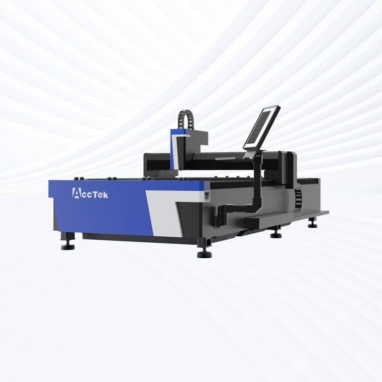
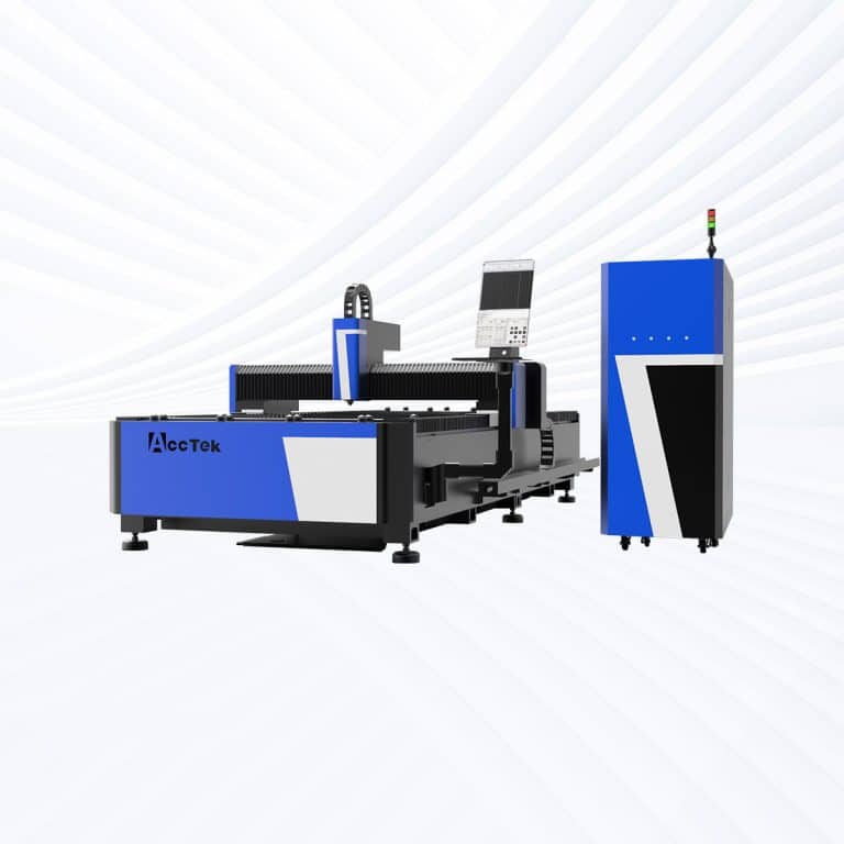
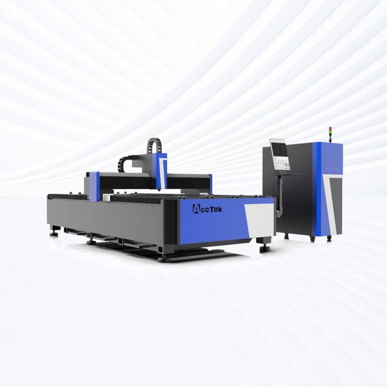
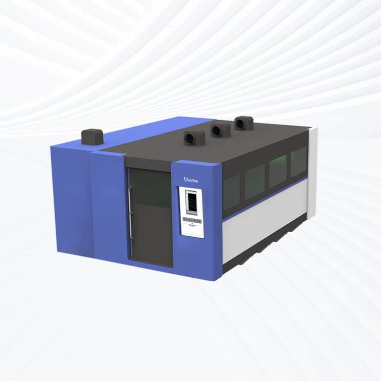
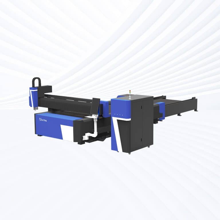
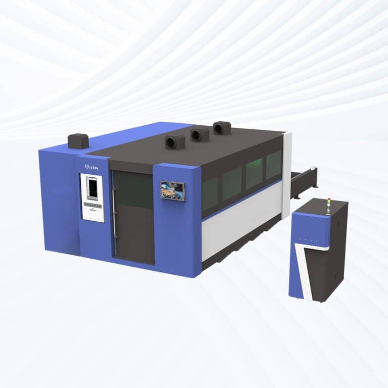
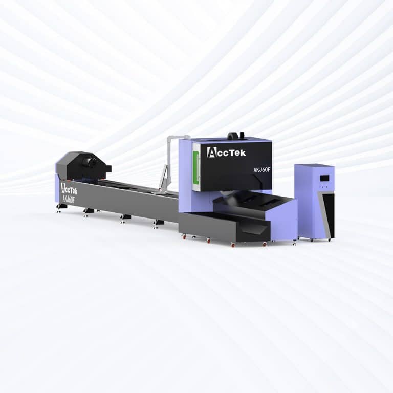
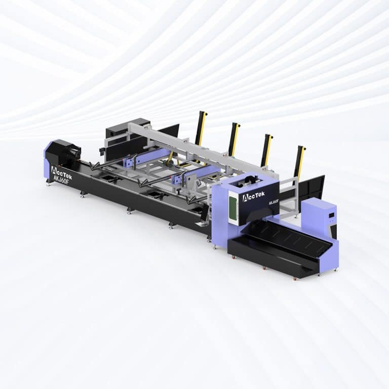
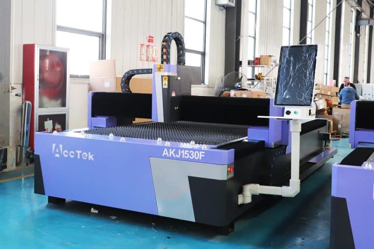
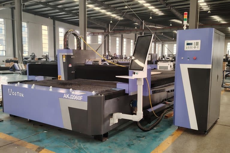
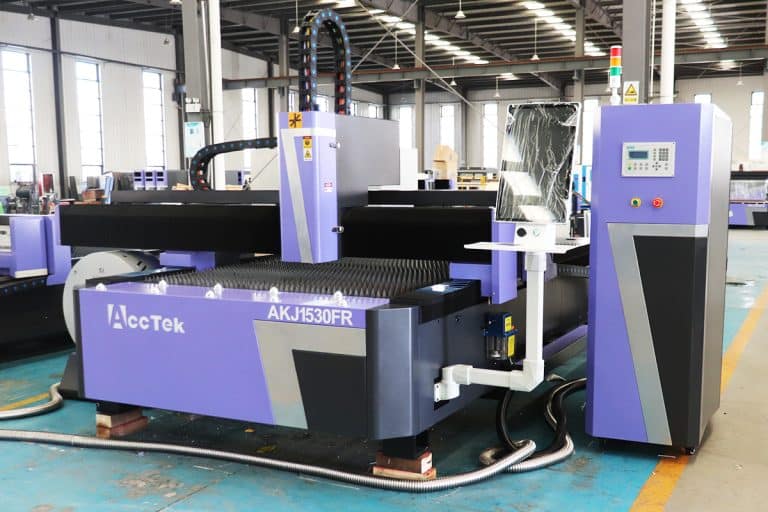
Laser Cutting Machines Suitable For Carbon Steel
Advantages of Laser Cutting Carbon Steel
High Cutting Speed and Productivity
Laser cutting carbon steel delivers very fast cutting speeds, especially when using oxygen assist gas on thicker plates. This high efficiency shortens production cycles, increases output, and helps manufacturers meet tight delivery schedules.
Excellent Cutting Precision
The focused laser beam produces accurate cuts with tight tolerances. This precision ensures consistent part dimensions, reliable repeatability, and precise hole placement, which is essential for mechanical assemblies and structural steel components.
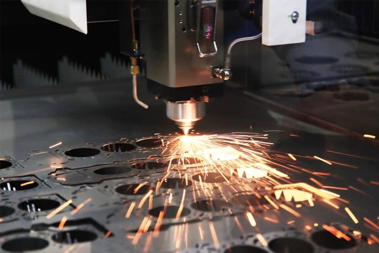
Clean and Consistent Edge Quality
Laser cutting produces smooth, uniform edges with minimal slag or burrs. In many cases, parts can be used directly after cutting, reducing or eliminating secondary grinding and finishing operations.
Wide Thickness Processing Range
Modern fiber laser machines can cut carbon steel from thin sheets to thick plates with stable performance. This flexibility allows one machine to handle a broad range of applications and production requirements.
Reduced Heat Distortion
The laser concentrates heat in a narrow cutting zone, minimizing the heat-affected area. This reduces warping and deformation, especially important when cutting thin carbon steel or parts with tight dimensional tolerances.
Flexible and Tool-Free Processing
Laser cutting does not require molds or mechanical tools. Design changes can be implemented quickly through software, making it ideal for prototyping, custom parts, and small-batch or mixed production runs.
Compatible Materials
- A36 Carbon Steel
- AISI 1010 Carbon Steel
- AISI 1018 Carbon Steel
- AISI 1020 Carbon Steel
- AISI 1030 Carbon Steel
- AISI 1040 Carbon Steel
- AISI 1050 Carbon Steel
- AISI 1060 Carbon Steel
- AISI 1070 Carbon Steel
- AISI 1080 Carbon Steel
- AISI 1090 Carbon Steel
- AISI 1100 Carbon Steel
- AISI 1117 Carbon Steel
- AISI 1120 Carbon Steel
- AISI 1141 Carbon Steel
- AISI 1144 Carbon Steel
- AISI 1215 Carbon Steel
- AISI 1219 Carbon Steel
- AISI 1220 Carbon Steel
- AISI 1300 Carbon Steel
- AISI 1340 Carbon Steel
- AISI 1400 Carbon Steel
- AISI 1440 Carbon Steel
- AISI 1500 Carbon Steel
- AISI 1518 Carbon Steel
- AISI 1550 Carbon Steel
- AISI 1600 Carbon Steel
- AISI 1620 Carbon Steel
- AISI 1630 Carbon Steel
- AISI 1650 Carbon Steel
- AISI 1710 Carbon Steel
- AISI 1720 Carbon Steel
- AISI 2011 Carbon Steel
- AISI 2024 Carbon Steel
- AISI 3030 Carbon Steel
- AISI 4130 Carbon Steel
- AISI 4140 Carbon Steel
- AISI 4150 Carbon Steel
- AISI 4340 Carbon Steel
- AISI 8620 Carbon Steel
Laser Cutting Carbon Steel VS Other Cutting Methods
| Comparison Item | Laser Cutting | Plasma Cutting | Waterjet Cutting | Flame Cutting |
|---|---|---|---|---|
| Cutting Precision | Very high accuracy | Moderate accuracy | Very high accuracy | Low accuracy |
| Edge Quality | Smooth, clean edges | Rough edges, dross | Smooth edges | Rough, oxidized edges |
| Heat-Affected Zone | Small and controlled | Large | None (cold cutting) | Very large |
| Cutting Speed | Very fast on thin to medium plates | Fast on thick plates | Slow | Slow |
| Suitable Thickness Range | Thin to thick plates | Medium to thick plates | Thin to very thick | Thick plates only |
| Detail & Complexity | Excellent for fine details | Limited detail | Excellent detail | Very limited detail |
| Kerf Width | Narrow kerf | Wide kerf | Moderate kerf | Wide kerf |
| Secondary Finishing | Minimal or none | Often required | Rarely required | Always required |
| Operating Cost | Moderate | Low | High | Low |
| Equipment Investment | Moderate to high | Low to moderate | High | Low |
| Automation Capability | Highly automated CNC | CNC capable | CNC capable | Mostly manual |
| Material Waste | Low waste | Moderate waste | Moderate waste | High waste |
| Production Volume | High-volume and flexible | Medium-volume | Low to medium volume | Low-volume |
| Environmental Impact | Low emissions, clean process | High fumes and noise | Water and abrasive waste | Heavy smoke and gases |
| Overall Cutting Quality | Excellent balance of speed and quality | Good for rough cuts | High quality, slower | Basic cutting only |
Laser Cutting Capacity For Carbon Steel
| Laser Power | Material Thickness (mm) | Cutting Speed (m/min) | Actual Laser Power (W) | Gas | Pressure (bar) | Nozzle Size (mm) | Focus Position (mm) | Cutting Height (mm) |
|---|---|---|---|---|---|---|---|---|
| 1KW | 1 | 10 | 1000 | N2/Air | 10 | 1.5S | 0 | 1 |
| 2 | 4 | 1000 | O2 | 2 | 1.2D | 3 | 0.8 | |
| 3 | 3 | 1000 | O2 | 0.6 | 1.2D | 3 | 0.8 | |
| 4 | 2.3 | 1000 | O2 | 0.6 | 1.2D | 3 | 0.8 | |
| 5 | 1.8 | 1000 | O2 | 0.6 | 1.2D | 3 | 0.8 | |
| 6 | 1.5 | 1000 | O2 | 0.6 | 1.5D | 3 | 0.8 | |
| 8 | 1.1 | 1000 | O2 | 0.6 | 1.5D | 3 | 0.8 | |
| 1.5KW | 1 | 20 | 1500 | N2/Air | 10 | 1.5S | 0 | 1 |
| 2 | 5 | 1500 | O2 | 2 | 1.2D | 3 | 0.8 | |
| 3 | 3.6 | 1500 | O2 | 0.6 | 1.2D | 3 | 0.8 | |
| 4 | 2.5 | 1500 | O2 | 0.6 | 1.2D | 3 | 0.8 | |
| 5 | 1.8 | 1500 | O2 | 0.6 | 1.2D | 3 | 0.8 | |
| 6 | 1.4 | 1500 | O2 | 0.6 | 1.5D | 3 | 0.8 | |
| 8 | 1.2 | 1500 | O2 | 0.6 | 1.5D | 3 | 0.8 | |
| 10 | 1 | 1500 | O2 | 0.6 | 2.0D | 2.5 | 0.8 | |
| 12 | 0.8 | 1500 | O2 | 0.6 | 2.5D | 2.5 | 0.8 | |
| 14 | 0.65 | 1500 | O2 | 0.6 | 3.0D | 2.5 | 0.8 | |
| 2KW | 1 | 25 | 2000 | N2/Air | 10 | 1.5S | 0 | 1 |
| 2 | 9 | 2000 | N2/Air | 10 | 2.0S | -1 | 0.5 | |
| 2 | 5.2 | 2000 | O2 | 0.6 | 1.0D | 3 | 0.8 | |
| 3 | 4.2 | 2000 | O2 | 0.6 | 1.0D | 3 | 0.8 | |
| 4 | 3 | 2000 | O2 | 0.6 | 1.0D | 3 | 0.8 | |
| 5 | 2.2 | 2000 | O2 | 0.6 | 1.2D | 3 | 0.8 | |
| 6 | 1.8 | 2000 | O2 | 0.6 | 1.2D | 3 | 0.8 | |
| 8 | 1.3 | 2000 | O2 | 0.6 | 2.0D | 2.5 | 0.8 | |
| 10 | 1.1 | 2000 | O2 | 0.5 | 2.0D | 2.5 | 0.8 | |
| 12 | 0.9 | 2000 | O2 | 0.5 | 2.5D | 2.5 | 0.8 | |
| 14 | 0.8 | 2000 | O2 | 0.5 | 3.0D | 2.5 | 0.8 | |
| 16 | 0.7 | 2000 | O2 | 0.6 | 3.5D | 2.5 | 0.8 | |
| 18 | 0.5 | 2000 | O2 | 0.6 | 4.0D | 3 | 0.8 | |
| 3KW | 1 | 28-35 | 3000 | N2/Air | 10 | 1.5S | 0 | 1 |
| 2 | 16-20 | 3000 | N2/Air | 10 | 2.0S | 0 | 0.5 | |
| 2 | 3.8-4.2 | 2100 | O2 | 1.6 | 1.0D | +3 | 0.8 | |
| 3 | 3.2-3.6 | 2100 | O2 | 0.6 | 1.0D | +4 | 0.8 | |
| 4 | 3-3.2 | 2400 | O2 | 0.6 | 1.0D | +4 | 0.8 | |
| 5 | 2.7-3 | 3000 | O2 | 0.6 | 1.2D | +4 | 0.8 | |
| 6 | 2.2-2.5 | 3000 | O2 | 0.6 | 1.2D | +4 | 0.8 | |
| 8 | 1.8-2.2 | 3000 | O2 | 0.6 | 1.2D | +4 | 0.8 | |
| 10 | 1-1.3 | 3000 | O2 | 0.6 | 1.2D | +4 | 0.8 | |
| 12 | 0.9-1 | 2400 | O2 | 0.6 | 3.0D | +4 | 0.8 | |
| 14 | 0.8-0.9 | 2400 | O2 | 0.6 | 3.0D | +4 | 0.8 | |
| 16 | 0.6-0.7 | 2400 | O2 | 0.6 | 3.5D | +4 | 0.8 | |
| 18 | 0.5-0.6 | 2400 | O2 | 0.6 | 4.0D | +4 | 0.8 | |
| 20 | 0.4-0.55 | 2400 | O2 | 0.6 | 4.0D | +4 | 0.8 | |
| 4KW | 1 | 28-35 | 4000 | N2/Air | 10 | 1.5S | 0 | 1 |
| 2 | 12-15 | 4000 | O2 | 10 | 2.0S | -1 | 0.5 | |
| 3 | 8-12 | 4000 | O2 | 10 | 2.0S | -1.5 | 0.5 | |
| 3 | 4-4.5 | 1800 | O2 | 0.6 | 1.2D | +3 | 0.8 | |
| 4 | 3-3.5 | 2400 | O2 | 0.6 | 1.2D | +3 | 0.8 | |
| 5 | 2.5-3 | 2400 | O2 | 0.6 | 1.2D | +3 | 0.8 | |
| 6 | 2.5-2.8 | 3000 | O2 | 0.6 | 1.2D | +3 | 0.8 | |
| 8 | 2-2.3 | 3600 | O2 | 0.6 | 1.2D | +3 | 0.8 | |
| 10 | 1.8-2 | 4000 | O2 | 0.6 | 1.2D | +3 | 0.8 | |
| 12 | 1-1.2 | 1800-2200 | O2 | 0.5 | 3.0D | +2.5 | 0.8 | |
| 14 | 0.9-1 | 1800-2200 | O2 | 0.5 | 3.5D | +2.5 | 0.8 | |
| 16 | 0.7-0.9 | 2200-2600 | O2 | 0.5 | 3.5D | +2.5 | 0.8 | |
| 18 | 0.6-0.7 | 2200-2600 | O2 | 0.5 | 4.0D | +2.5 | 0.8 | |
| 20 | 0.55-0.65 | 2200-2600 | O2 | 0.5 | 4.0D | +3 | 0.8 | |
| 22 | 0.5-0.6 | 2200-2800 | O2 | 0.5 | 4.5D | +3 | 0.8 | |
| 6KW | 1 | 35-45 | 6000 | N2/Air | 12 | 1.5S | 0 | 1 |
| 2 | 20-25 | 6000 | N2/Air | 12 | 2.0S | -1 | 0.5 | |
| 3 | 12-14 | 6000 | N2/Air | 14 | 2.0S | -1.5 | 0.5 | |
| 4 | 8-10 | 6000 | N2/Air | 14 | 2.0S | -2 | 0.5 | |
| 5 | 6-7 | 6000 | N2/Air | 16 | 3.0S | -2.5 | 0.5 | |
| 6 | 5-6 | 6000 | N2/Air | 16 | 3.5S | -3 | 0.5 | |
| 3 | 3.5-4.2 | 2400 | O2 | 0.6 | 1.2E | +3 | 0.8 | |
| 4 | 3.3-3.8 | 2400 | O2 | 0.6 | 1.2E | +3 | 0.8 | |
| 5 | 3-3.6 | 3000 | O2 | 0.6 | 1.2E | +3 | 0.8 | |
| 6 | 2.7-3.2 | 3300 | O2 | 0.6 | 1.2E | +3 | 0.8 | |
| 8 | 2.2-2.5 | 4200 | O2 | 0.6 | 1.2E | +3 | 0.8 | |
| 10 | 2.0-2.3 | 5500 | O2 | 0.6 | 1.2E | +4 | 0.8 | |
| 12 | 0.9-1 | 2200 | O2 | 0.6 | 3.0D | +2.5 | 0.8 | |
| 12 | 1.9-2.1 | 6000 | O2 | 0.6 | 1.2E | +5 | 0.8 | |
| 14 | 0.8-0.9 | 2200 | O2 | 0.6 | 3.5D | +2.5 | 0.8 | |
| 14 | 1.4-1.7 | 6000 | O2 | 0.6 | 1.4E | +5 | 1 | |
| 16 | 0.8-0.9 | 2200 | O2 | 0.6 | 4.0D | +2.5 | 0.8 | |
| 16 | 1.2-1.4 | 6000 | O2 | 0.6 | 1.4E | +6 | 1 | |
| 18 | 0.65-0.75 | 2200 | O2 | 0.6 | 4.0D | +2.5 | 0.8 | |
| 18 | 0.8 | 6000 | O2 | 0.6 | 1.6S | +12 | 0.3 | |
| 20 | 0.5-0.6 | 2400 | O2 | 0.6 | 4.0D | +3 | 0.8 | |
| 20 | 0.6-0.7 | 6000 | O2 | 0.6 | 1.6S | +13 | 0.3 | |
| 22 | 0.45-0.5 | 2400 | O2 | 0.6 | 4.0D | +3 | 0.8 | |
| 22 | 0.5-0.6 | 6000 | O2 | 0.6 | 1.6S | +13 | 0.3 | |
| 12KW | 1 | 50-60 | 12000 | N2/Air | 12 | 1.5S | 0 | 1 |
| 2 | 35-40 | 12000 | N2/Air | 12 | 2.0S | 0 | 0.5 | |
| 3 | 28-33 | 12000 | N2/Air | 13 | 2.0S | 0 | 0.5 | |
| 4 | 20-24 | 12000 | N2/Air | 13 | 2.5S | 0 | 0.5 | |
| 5 | 15-18 | 12000 | N2/Air | 13 | 2.5S | 0 | 0.5 | |
| 6 | 10-13 | 12000 | N2/Air | 13 | 2.5S | 0 | 0.5 | |
| 8 | 7-10 | 12000 | N2/Air | 13 | 3.0S | -1.5 | 0.5 | |
| 10 | 6-6.5 | 12000 | N2/Air | 13 | 4.0S | -3 | 0.5 | |
| 10 | 2-2.3 | 6000 | O2 | 0.6 | 1.2E | +6 | 0.8 | |
| 12 | 1.8-2 | 7500 | O2 | 0.6 | 1.2E | +7 | 0.8 | |
| 14 | 1.6-1.8 | 8500 | O2 | 0.6 | 1.4E | +7 | 0.8 | |
| 16 | 1.5-1.6 | 9500 | O2 | 0.6 | 1.4E | +8 | 0.8 | |
| 20 | 1.3-1.4 | 12000 | O2 | 0.6 | 1.6E | +8 | 0.8 | |
| 22 | 0.9-1 | 12000 | O2 | 0.7 | 1.8E | +9 | 0.8 | |
| 22 | 1-1.2 | 12000 | O2 | 0.7 | 1.4SP | +11 | 0.5 | |
| 25 | 0.7-0.9 | 12000 | O2 | 0.7 | 1.8E | +11 | 0.8 | |
| 25 | 0.8-1 | 12000 | O2 | 0.7 | 1.5SP | +12 | 0.5 | |
| 12 | 3-3.5 | 12000 | O2 | 1 | 1.6SP | -10 | 1.5 | |
| 14 | 3-3.2 | 12000 | O2 | 1 | 1.6SP | -10 | 1.5 | |
| 16 | 2.8-3 | 12000 | O2 | 1 | 1.6SP | -12 | 1.5 | |
| 20 | 2-2.3 | 12000 | O2 | 1.2 | 1.6SP | -12 | 1.5 | |
| 25 | 1.1-1.3 | 12000 | O2 | 1.3 | 1.8SP | -14 | 1.5 | |
| 30 | 0.9-1 | 12000 | O2 | 1.4 | 1.8SP | -14 | 1.5 | |
| 20KW | 5 | 23-28 | 20000 | N2/Air | 8 | 3.0S | 0 | 0.5 |
| 6 | 18-20 | 20000 | N2/Air | 8 | 3.0S | -0.5 | 0.5 | |
| 8 | 14-16 | 20000 | N2/Air | 8 | 3.0S | -1 | 0.5 | |
| 10 | 9-12 | 20000 | N2/Air | 8 | 3.5S | -1.5 | 0.5 | |
| 12 | 8-10 | 20000 | N2/Air | 8 | 3.5S | -2 | 0.5 | |
| 14 | 6-8 | 20000 | N2/Air | 8 | 4.0S | -3 | 0.5 | |
| 16 | 5-6 | 20000 | N2/Air | 8 | 5.0S | -4 | 0.5 | |
| 18 | 3.2-4 | 20000 | N2/Air | 10 | 6.0S | -6 | 0.5 | |
| 20 | 2.7-3.2 | 20000 | N2/Air | 10 | 6.0S | -8 | 0.5 | |
| 10 | 2-2.3 | 6000 | O2 | 0.6 | 1.2E | +8 | 0.8 | |
| 12 | 1.8-2 | 7500 | O2 | 0.6 | 1.2E | +9 | 0.8 | |
| 14 | 1.6-1.8 | 8500 | O2 | 0.6 | 1.4E | +10 | 0.8 | |
| 16 | 1.5-1.6 | 9500 | O2 | 0.6 | 1.4E | +11 | 0.8 | |
| 20 | 1.3-1.4 | 12000 | O2 | 0.6 | 1.6E | +12 | 0.8 | |
| 22 | 1.2-1.3 | 20000 | O2 | 0.7 | 1.8E | +12.5 | 0.8 | |
| 22 | 1.4-1.5 | 20000 | O2 | 0.7 | 1.4SP | +13 | 0.5 | |
| 25 | 1.2-1.4 | 20000 | O2 | 1.0 | 1.5SP | +13 | 0.4 | |
| 30 | 1.2-1.3 | 20000 | O2 | 1.2 | 1.5SP | +13.5 | 0.4 | |
| 40 | 0.6-0.9 | 20000 | O2 | 1.4 | 1.6SP | +14 | 0.4 | |
| 40 | 0.3-0.6 | 20000 | O2 | 1.6 | 1.8E | +13 | 2 | |
| 50 | 0.2-0.3 | 20000 | O2 | 1.6 | 1.8E | +13 | 2 | |
| 12 | 3.2-3.5 | 20000 | O2 | 1 | 1.6SP | -10 | 1.5 | |
| 14 | 3-3.2 | 20000 | O2 | 1 | 1.6SP | -10 | 1.5 | |
| 16 | 3-3.1 | 20000 | O2 | 1 | 1.6SP | -12 | 1.5 | |
| 20 | 2.8-3 | 20000 | O2 | 1.2 | 1.6SP | -12 | 1.5 | |
| 25 | 2.4-2.6 | 20000 | O2 | 1.3 | 1.8SP | -14 | 1.5 | |
| 30 | 1.7-1.9 | 20000 | O2 | 1.4 | 1.8SP | -14 | 1.5 | |
| 35 | 1.4-1.6 | 20000 | O2 | 1.4 | 2.0SP | -15 | 1.5 | |
| 40 | 1-1.2 | 20000 | O2 | 1.5 | 2.5S | -15 | 1.5 | |
| 45 | 0.8-0.9 | 20000 | O2 | 1.6 | 2.5S | -17 | 1.5 | |
| 30KW | 5 | 24-30 | 30000 | N2/Air | 8 | 3.0S | 0 | 0.5 |
| 6 | 25-28 | 30000 | N2/Air | 8 | 3.0S | -0.5 | 0.5 | |
| 8 | 18-22 | 30000 | N2/Air | 8 | 3.0S | -1 | 0.5 | |
| 10 | 14-17 | 30000 | N2/Air | 8 | 3.5S | -1.5 | 0.5 | |
| 12 | 11-13 | 30000 | N2/Air | 8 | 3.5S | -2 | 0.5 | |
| 14 | 8-10 | 30000 | N2/Air | 8 | 4.0S | -3 | 0.5 | |
| 16 | 7.5-8.5 | 30000 | N2/Air | 8 | 5.0S | -4 | 0.5 | |
| 18 | 5.5-6.5 | 30000 | N2/Air | 10 | 6.0S | -6 | 0.5 | |
| 20 | 5-5.5 | 30000 | N2/Air | 10 | 6.0S | -8 | 0.5 | |
| 25 | 3-3.5 | 30000 | N2/Air | 10 | 6.0S | -12 | 0.5 | |
| 10 | 2-2.3 | 6000 | O2 | 0.6 | 1.2E | +8 | 0.8 | |
| 12 | 1.8-2 | 7500 | O2 | 0.6 | 1.2E | +9 | 0.8 | |
| 14 | 1.6-1.8 | 8500 | O2 | 0.6 | 1.4E | +10 | 0.8 | |
| 16 | 1.6-1.8 | 9500 | O2 | 0.6 | 1.4E | +11 | 0.8 | |
| 20 | 1.5-1.6 | 12000 | O2 | 0.6 | 1.6E | +12 | 0.8 | |
| 22 | 1.4-1.5 | 20000 | O2 | 0.7 | 1.4SP | +13 | 0.5 | |
| 25 | 1.2-1.4 | 20000 | O2 | 1.0 | 1.5SP | +13 | 0.4 | |
| 30 | 1.2-1.3 | 20000 | O2 | 1.2 | 1.5SP | +13.5 | 0.4 | |
| 40 | 0.6-0.9 | 20000 | O2 | 1.4 | 1.6SP | +14 | 0.4 | |
| 40 | 0.3-0.6 | 20000 | O2 | 1.6 | 1.8E | +13 | 2 | |
| 50 | 0.3-0.5 | 20000 | O2 | 1.6 | 1.8E | +13 | 2 | |
| 50 | 0.6-0.8 | 30000 | O2 | 1.6 | 1.8SP | +14 | 0.4 | |
| 12 | 3.2-3.5 | 30000 | O2 | 1 | 1.6SP | -10 | 1.5 | |
| 14 | 3-3.2 | 30000 | O2 | 1 | 1.6SP | -10 | 1.5 | |
| 16 | 3-3.1 | 30000 | O2 | 1 | 1.6SP | -12 | 1.5 | |
| 20 | 2.8-3 | 30000 | O2 | 1.2 | 1.6SP | -12 | 1.5 | |
| 25 | 2.6-2.8 | 30000 | O2 | 1.3 | 1.8SP | -14 | 1.5 | |
| 30 | 2.2-2.6 | 30000 | O2 | 1.4 | 1.8SP | -14 | 1.5 | |
| 35 | 1.4-1.6 | 30000 | O2 | 1.4 | 2.0SP | -15 | 1.5 | |
| 40 | 1-1.4 | 30000 | O2 | 1.5 | 2.5S | -15 | 1.5 | |
| 45 | 0.8-0.9 | 30000 | O2 | 1.6 | 2.5S | -17 | 1.5 | |
| 40KW | 5 | 28-32 | 40000 | N2/Air | 8 | 3.0B | 0 | 0.3 |
| 6 | 25-28 | 40000 | N2/Air | 8 | 3.0B | 0 | 0.3 | |
| 8 | 22-24 | 40000 | N2/Air | 8 | 3.0B | 0 | 0.3 | |
| 10 | 16-20 | 40000 | N2/Air | 8 | 3.5B | -0.5 | 0.3 | |
| 12 | 14-17 | 40000 | N2/Air | 8 | 3.5B | -0.5 | 0.3 | |
| 14 | 11-13 | 40000 | N2/Air | 8 | 5.0B | -1 | 0.3 | |
| 16 | 8-9.5 | 40000 | N2/Air | 8 | 5.0B | -1 | 0.3 | |
| 18 | 7.5-8.5 | 40000 | N2/Air | 8 | 6.0B | -2 | 0.3 | |
| 20 | 7-8 | 40000 | N2/Air | 8 | 6.0B | -3 | 0.3 | |
| 25 | 5-5.5 | 40000 | N2/Air | 6 | 8.0B | -5 | 0.3 | |
| 30 | 3-4 | 40000 | N2/Air | 6 | 8.0B | -7 | 0.3 | |
| 40 | 1.5-2 | 40000 | N2/Air | 4 | 10.0ECU | -13 | 0.3 | |
| 10 | 2-2.3 | 6000 | O2 | 0.6 | 1.2E | +11 | 0.8 | |
| 12 | 1.8-2 | 7500 | O2 | 0.6 | 1.2E | +12 | 0.8 | |
| 14 | 1.6-1.8 | 8500 | O2 | 0.6 | 1.4E | +13 | 0.8 | |
| 16 | 1.6-1.8 | 9500 | O2 | 0.6 | 1.4E | +14 | 0.8 | |
| 20 | 1.5-1.6 | 12000 | O2 | 0.6 | 1.6E | +15 | 0.8 | |
| 22 | 1.4-1.5 | 18000 | O2 | 0.7 | 1.4SP | +17 | 0.5 | |
| 25 | 1.2-1.4 | 18000 | O2 | 0.65 | 1.6SP | +19 | 0.3 | |
| 30 | 1.2-1.3 | 18000 | O2 | 0.6 | 1.8SP | +23 | 0.3 | |
| 40 | 0.9-1.1 | 26000 | O2 | 0.8 | 2.2SP | +25 | 0.3 | |
| 40 | 0.3-0.6 | 20000 | O2 | 1.6 | 1.8E | +18 | 2 | |
| 50 | 0.3-0.5 | 25000 | O2 | 1.6 | 1.8E | +18 | 2 | |
| 50 | 0.7-0.9 | 40000 | O2 | 1.2 | 2.2SP | +25 | 0.3 | |
| 60 | 0.6-0.8 | 40000 | O2 | 1.5 | 2.4SP | +25 | 0.3 | |
| 70 | 0.5-0.7 | 40000 | O2 | 1.5 | 2.4SP | +25 | 0.3 | |
| 12 | 3.2-3.5 | 20000 | O2 | 1 | 1.6SP | -9 | 1.5 | |
| 14 | 3-3.2 | 20000 | O2 | 1 | 1.6SP | -10 | 1.5 | |
| 16 | 3-3.1 | 20000 | O2 | 1 | 1.6SP | -10 | 1.5 | |
| 20 | 2.8-3.2 | 20000 | O2 | 1 | 1.8SP | -11 | 1.5 | |
| 25 | 2.4-2.8 | 40000 | O2 | 1 | 2.5SP | -17 | 2.5 | |
| 30 | 2.4-2.6 | 40000 | O2 | 1.2 | 2.5SP | -18 | 1.5 | |
| 35 | 2.3-2.6 | 40000 | O2 | 1.3 | 2.5SP | -20 | 1.5 | |
| 40 | 2-2.3 | 40000 | O2 | 1.5 | 3.0SS | -23 | 1.5 | |
| 50 | 1.2-1.6 | 40000 | O2 | 1.6 | 3.0SS | -25 | 1.5 | |
| 60 | 1-1.3 | 40000 | O2 | 1.8 | 3.0SS | -27 | 3 | |
| 70 | 0.6-0.8 | 40000 | O2 | 2.0 | 3.0SS | -34 | 3 |
Applications of Laser Cutting Carbon Steel


Customer Testimonials
Related Resources
Understanding The Odors Associated With Laser Cutting
This article provides a comprehensive guide to laser cutting odors, explaining the causes of odors, material-specific odors, health risks, and practical strategies for effectively controlling odors and ensuring safer operation.
What Safety Measures Should Be Taken When Operating Laser Cutting Machines
This article teaches the basic safety measures for operating a laser cutting machine, including hazard awareness, engineering controls, PPE, fire prevention, ventilation, training, and emergency response drills.
Addressing the Challenges of Fiber Laser Cutting: Common Problems and Solutions
This article explores common challenges in fiber laser cutting, including material-related issues, machine performance, and operator-related problems, offering practical solutions to optimize cutting quality and efficiency.
Precautions for Operating Laser Cutting Machines
This article provides a detailed overview of basic precautions for operating laser cutting machines, covering safety risks, proper setup, operating guidelines, maintenance procedures, and emergency preparedness.
Frequently Asked Questions
Why Does Carbon Content Affect Laser Cutting?
- Laser Energy Absorption: Higher carbon content generally increases a material’s ability to absorb laser energy. Carbon-rich steels tend to be darker and less reflective than low-carbon steels, allowing more laser energy to enter the material. Improved absorption makes it easier to initiate cutting and maintain a stable kerf, while low-carbon steels may require slightly higher power or optimized focus to achieve the same effect.
- Melting and Oxidation Behavior: Carbon affects how steel reacts during oxygen-assisted laser cutting. In higher-carbon steels, carbon participates in exothermic oxidation reactions, releasing additional heat. This extra thermal energy can increase cutting efficiency but may also make the process more aggressive if not carefully controlled. Low-carbon steels exhibit more predictable and stable oxidation, making them easier to cut cleanly.
- Heat-Affected Zone (HAZ) and Microstructure: As carbon content increases, steel becomes more sensitive to rapid heating and cooling. Laser cutting introduces steep thermal gradients, and higher-carbon steels are more prone to hardening in the heat-affected zone. This can lead to increased brittleness, microcracking, or hardness variation near the cut edge, which may affect downstream machining or welding.
- Edge Quality and Burr Formation: Higher carbon steels can produce rougher edges if parameters are not optimized. Excessive heat input may cause localized melting and resolidification, increasing burr formation or dross. Low-carbon steels typically yield smoother edges and more consistent cut quality under a wider range of settings.
- Cutting Speed Sensitivity: Materials with higher carbon content often require tighter control over cutting speed. Cutting too fast may result in incomplete oxidation and rough edges, while cutting too slowly can overheat the material and worsen HAZ effects. Low-carbon steels are more forgiving and easier to process at higher speeds.
- Post-Cut Performance Considerations: The hardness introduced by laser cutting higher-carbon steels may necessitate post-processing, such as stress relief or edge finishing, depending on application requirements.
Why Do Microcracks Occur When Laser Cutting Carbon Steel?
- Rapid Heating and Cooling Rates: Laser cutting concentrates a large amount of energy into a very small area. The cut zone heats up almost instantly and then cools rapidly once the laser moves on. This sudden temperature change creates steep thermal gradients between the cut edge and the surrounding material. The resulting expansion and contraction generate internal stresses that can exceed the material’s ability to deform plastically, leading to microcracks.
- Carbon Content and Hardening Effects: Carbon steel becomes more sensitive to rapid cooling as carbon content increases. During laser cutting, the heat-affected zone may cool so quickly that it forms hard microstructures such as martensite. While martensite is strong, it is also brittle, making it more prone to cracking under residual stress.
- Heat-Affected Zone (HAZ) Stress Concentration: The HAZ experiences structural changes without fully melting. Differences in microstructure and hardness between the cut edge and the base material create stress concentrations. These localized stress points are common initiation sites for microcracks, especially in medium- and high-carbon steels.
- Excessive Heat Input: Using overly high laser power or slow cutting speeds increases heat input, enlarging the heat-affected zone. A larger HAZ intensifies thermal stress and raises the likelihood of cracking. Excessive heat also promotes grain growth, which reduces toughness and further contributes to crack formation.
- Assist Gas Influence: Oxygen-assisted laser cutting introduces additional heat through oxidation. While this improves cutting efficiency, it can also increase local temperatures and thermal stress if not carefully controlled. Improper gas pressure or flow can worsen edge conditions and promote cracking.
- Material Condition and Internal Stress: Pre-existing stresses from rolling, forming, or welding can combine with laser-induced stresses. When these stresses interact, the risk of microcrack formation increases, even if cutting parameters are otherwise acceptable.
- Post-Cut Cooling Conditions: Uncontrolled cooling, such as exposure to cold airflow or contact with a cold cutting table, can intensify quenching effects at the cut edge, increasing brittleness and crack susceptibility.
How Does The Choice Of Assist Gas Affect Carbon Steel Cutting?
- Oxygen (O2): Oxygen is the most commonly used assist gas for cutting carbon steel. It reacts exothermically with molten iron, generating additional heat during cutting. This extra heat significantly increases cutting speed and allows thicker carbon steel to be cut with lower laser power. However, the oxidation process creates an oxide layer on the cut edge, which may require secondary cleaning if the part will be welded, painted, or coated.
- Nitrogen (N2): Nitrogen is an inert gas and does not react with carbon steel during cutting. Instead of adding heat, it relies solely on laser energy to melt the material. This produces clean, bright edges with no oxide layer, making nitrogen ideal for parts requiring high surface quality or minimal post-processing. The trade-off is a slower cutting speed and higher gas consumption, especially for thicker plates.
- Compressed Air: Compressed air is sometimes used as a budget-friendly alternative. Since air contains oxygen, it behaves similarly to oxygen cutting but in a less controlled way. This often results in more oxidation, rougher edges, and inconsistent cut quality. Air cutting is typically limited to thin carbon steel and non-critical applications.
- Impact on Heat-Affected Zone (HAZ): Oxygen-assisted cutting introduces more heat into the material, which can enlarge the heat-affected zone. This may increase hardness and residual stress near the cut edge. Nitrogen cutting produces a smaller HAZ, reducing the risk of microcracks and improving mechanical consistency.
- Dross and Edge Quality Control: Gas pressure and purity play a key role in removing molten steel. Oxygen tends to produce minimal dross at optimized settings, while nitrogen requires higher pressure to achieve similar results. Poor gas flow or contamination can quickly degrade cut quality regardless of gas type.
- Material Thickness Considerations: For thick carbon steel, oxygen is generally preferred due to its speed and efficiency. For thin to medium thickness where appearance matters, nitrogen offers superior edge quality.
Why Does Laser Cutting Carbon Steel Discolor?
- Oxidation During Cutting: Carbon steel readily reacts with oxygen at high temperatures. During laser cutting—especially when oxygen is used as the assist gas—the molten steel oxidizes rapidly. This oxidation forms iron oxides on the cut edge and surrounding surface, producing dark gray, blue, brown, or black discoloration. The intensity of the color depends on temperature and exposure time.
- Heat-Affected Zone (HAZ) Formation: The heat-affected zone is the area adjacent to the cut that experiences high temperatures without melting. Thermal exposure alters the steel’s surface chemistry and microstructure. As the steel cools, thin oxide layers form in the HAZ, refracting light differently and creating visible color changes. A larger HAZ generally results in more pronounced discoloration.
- Assist Gas Selection: The choice of assist gas has a major influence on discoloration. Oxygen-assisted cutting promotes oxidation and produces darker edges. Nitrogen-assisted cutting, by contrast, minimizes oxidation and results in cleaner, brighter cut surfaces with little to no discoloration. Compressed air falls somewhere in between, often causing inconsistent coloring.
- Excessive Heat Input: High laser power, slow cutting speed, or improper focus increases heat input. Prolonged heating allows thicker oxide layers to develop, deepening discoloration and expanding the affected area. Optimized parameters help reduce unnecessary thermal exposure and limit color change.
- Material Thickness and Composition: Thicker carbon steel retains heat longer, which encourages oxidation during cooling. Higher carbon content can also intensify color variation by influencing how the steel reacts to heat and oxygen at the cut edge.
- Surface Condition Before Cutting: Mill scale, oil, or surface contaminants can burn or oxidize unevenly during cutting. These residues often exaggerate discoloration and create blotchy or uneven color patterns near the cut.
- Cooling Environment: Rapid cooling in open air promotes oxide formation. Environmental airflow and ambient oxygen levels can influence how quickly oxidation occurs after cutting.
Why Is Preheating Rarely Needed When Laser Cutting Carbon Steel?
- Highly Concentrated Energy Input: Laser cutting focuses a powerful beam of light into a very small spot, instantly raising the temperature at the cutting point to the melting or oxidation threshold. This intense, localized heating effectively replaces the need for preheating, as the material reaches cutting temperature almost immediately.
- Favorable Absorption Characteristics of Carbon Steel: Carbon steel absorbs laser energy more efficiently than highly reflective metals such as aluminum or brass. Its relatively low reflectivity allows the laser to couple energy into the material quickly, making it easy to initiate piercing and maintain a stable cut without pre-warming the workpiece.
- Oxygen-Assisted Cutting Enhances Heat Generation: When oxygen is used as the assist gas, an exothermic reaction occurs between oxygen and iron. This reaction generates additional heat at the cut front, further reducing the need for preheating. The added thermal energy helps sustain cutting even on thicker carbon steel plates.
- Moderate Thermal Conductivity: Carbon steel has lower thermal conductivity compared to non-ferrous metals like aluminum or copper alloys. This means heat stays concentrated near the cutting zone rather than spreading rapidly through the material. As a result, sufficient cutting temperatures are achieved without raising the overall temperature of the workpiece.
- Controlled Heat-Affected Zone: Laser cutting produces a relatively narrow heat-affected zone. Because the surrounding material remains relatively cool, the risk of large-scale thermal stress is reduced, eliminating one of the traditional reasons for preheating in other cutting or welding processes.
- Material Thickness and Composition Compatibility: Most low- and medium-carbon steels commonly processed by laser cutting are well within the capability range of modern laser cutting systems. Their metallurgical structure does not typically require preheating to prevent cracking or hardness issues during cutting.
- Process Efficiency and Productivity: Skipping preheating simplifies workflow and reduces energy consumption, setup time, and operating costs. This efficiency is one of the key advantages of laser cutting over other thermal methods.
Why Do The Sparks Produced When Laser Cutting Carbon Steel Last Longer?
- Exothermic Oxidation Reaction: Carbon steel is most commonly cut using oxygen as the assist gas. When the laser heats the steel to ignition temperature, oxygen reacts with molten iron in an exothermic oxidation process. This reaction releases additional heat beyond what the laser alone provides. The molten metal particles ejected from the cut continue reacting with oxygen as they travel through the air, allowing them to glow and burn longer, which makes the sparks appear more persistent.
- Iron-Rich Molten Particles: The sparks produced during cutting are actually small droplets of molten or semi-molten iron. Iron has a relatively high melting point and retains heat well, allowing these particles to stay incandescent longer before cooling. As a result, sparks from carbon steel remain visible over a longer distance and time compared to metals that cool or solidify more quickly.
- Carbon Content Contribution: Carbon within the steel can also participate in oxidation reactions. As molten particles are expelled, carbon reacts with oxygen, sustaining combustion and extending the lifespan of the sparks. Higher carbon content can intensify this effect, producing brighter and longer-lasting spark trails.
- Lower Thermal Conductivity Compared to Non-Ferrous Metals: Carbon steel has lower thermal conductivity than metals such as aluminum or brass. This means heat is not dissipated as quickly from the molten particles. Retained heat allows the sparks to stay hot and luminous for a longer duration after ejection.
- Assist Gas Flow and Particle Trajectory: High-pressure oxygen assists in forcefully expelling molten material from the kerf. This strong gas flow propels particles farther away from the cut zone, giving them more time in the air to oxidize and glow before cooling. The result is a longer, more visible spark stream.
- Cutting Speed and Heat Input: Slower cutting speeds or thicker materials increase heat input, producing larger molten droplets. Larger particles take longer to cool, which further extends spark duration.
- Surface Oxide Formation: As sparks travel through the air, continuous oxidation forms iron oxide layers on their surface. This ongoing reaction releases heat, helping sustain visible glowing.
Why Does Laser-Cutting Carbon Steel Shorten Lens Life?
- Metal Vapor and Spatter Contamination: During laser cutting, molten carbon steel is expelled from the kerf as fine droplets and vaporized metal. These particles can travel upward and deposit on the protective window or focusing lens. Even microscopic contamination absorbs laser energy, causing localized heating that gradually burns or pits the lens surface, reducing optical clarity and lifespan.
- Oxide Smoke and Fume Deposition: Oxygen-assisted cutting produces large amounts of iron oxide fumes. These fine oxide particles can settle on optical components if the sealing air or fume extraction system is insufficient. Over time, oxide buildup creates a thin absorbing layer on the lens, increasing thermal load and accelerating damage.
- Exothermic Reaction Increases Heat Exposure: When oxygen reacts with molten iron, it generates additional heat beyond the laser’s energy. This raises the overall thermal intensity near the cutting head. The increased radiant heat places extra thermal stress on the lens and protective glass, promoting coating degradation and microcracking.
- Back Reflection and Scattered Energy: Although carbon steel is less reflective than non-ferrous metals, irregular molten surfaces and unstable cutting conditions can scatter laser energy upward. This stray radiation can partially reflect into the optical path, heating lens coatings unevenly and contributing to premature failure.
- High Cutting Frequency and Duty Cycle: Carbon steel is one of the most commonly laser-cut materials in industrial environments. High production volumes mean the lens is exposed to contaminants and thermal stress for extended periods. Continuous operation without adequate cleaning intervals significantly shortens lens service life.
- Inadequate Nozzle or Air Knife Performance: The nozzle and protective airflow are designed to shield optics from debris. If nozzle alignment is off, air pressure is insufficient, or filters are clogged, contaminants can more easily reach the lens. This increases the rate of fouling and thermal damage.
- Thermal Shock from Rapid Cycling: Laser cutting involves repeated rapid heating and cooling cycles. Over time, this thermal cycling can degrade anti-reflective coatings on the lens, making them more vulnerable to absorption and cracking.
How Does Laser-Cutting Carbon Steel Affect Maintenance Cycles?
- Optics Cleaning and Replacement Frequency: Carbon steel cutting—especially with oxygen assist gas—produces iron oxide fumes and fine metal particles. These contaminants can settle on protective windows and focusing lenses, requiring more frequent cleaning. If not removed promptly, buildup absorbs laser energy and accelerates lens wear, shortening replacement intervals.
- Nozzle Inspection and Wear: Molten steel spatter and slag can adhere to the nozzle tip, affecting gas flow and beam alignment. As a result, nozzles must be inspected and cleaned regularly, and replacement cycles are often shorter compared to cutting cleaner materials such as stainless steel with nitrogen.
- Assist Gas System Maintenance: Oxygen systems used for carbon steel cutting require careful monitoring. Regulators, valves, and gas lines are exposed to high temperatures and reactive environments, increasing wear. Regular leak checks and component inspections become a necessary part of the maintenance routine.
- Fume Extraction and Filter Servicing: Laser cutting carbon steel generates heavy oxide smoke and dust. This places a high load on fume extraction systems, causing filters to clog more quickly. Filter replacement and duct cleaning intervals are therefore shorter to maintain proper airflow and prevent contamination of optics and mechanical components.
- Cutting Table and Slat Cleaning: Oxidized slag and molten steel droplets accumulate on cutting slats and trays. Without routine cleaning, buildup can affect part flatness, interfere with material handling, and increase fire risk. Maintenance cycles for table cleaning are more frequent in high-volume carbon steel operations.
- Motion System and Mechanical Wear: While not directly abrasive, the dust generated during cutting can settle on linear guides and drive systems if seals are compromised. This requires regular inspection, cleaning, and lubrication to prevent premature mechanical wear.
- Calibration and Process Checks: Thermal cycling and continuous operation can gradually affect focus height sensors, beam alignment, and cutting consistency. Periodic calibration checks are needed to maintain accuracy and prevent quality drift.